Design and Performance Evaluation of a Novel Wearable Parallel Mechanism for Ankle Rehabilitation
 Shiping Zuo
 Jianfeng Li
 Mingjie Dong
 Xiaodong Zhou
 Wenpei Fan
 Yuan Kong
- 1College of Mechanical Engineering and Applied Electronics Technology, Beijing University of Technology, Beijing, China
- 2Beijing Institute of Control Engineering, Beijing, China
Repetitive and intensive physiotherapy is indispensable to patients with ankle disabilities. Increasingly robot-assisted technology has been employed in the treatment to reduce the burden of the therapists and the related costs of the patients. This paper proposes a configuration of a wearable parallel mechanism to supplement the equipment selection for ankle rehabilitation. The kinematic analysis, i.e., the inverse position solution and Jacobian matrices, is elaborated. Several performance indices, including the reachable workspace index, motion isotropy index, force transfer index, and maximum torque index, are developed based on the derived kinematic solution. Moreover, according to the proposed kinematic configuration and wearable design concept, the mechanical structure that contains a basic machine-drive system and a multi-model position/force data collection system is designed in detail. Finally, the results of the performance evaluation indicate that the wearable parallel robot possesses sufficient motion isotropy, high force transfer performance, and large maximum torque performance within a large workspace that can cover all possible range of motion of human ankle complex, and is suitable for ankle rehabilitation.
Introduction
As the population ages, increasingly more individuals experience ankle disabilities caused by stroke and cerebral palsy, which may lead to lack of mobilization, irregular pain of body, insufficient capacity to support weight, and chronic joint instability. During the conventional manually physiotherapy, human ankle complex (HAC) is moved by a physical therapist with its range of motion (ROM). However, it possesses many limitations such as, the duration inconsistency and frequency indetermination of the treatment procedures, the physical demand, and experience requirement of the therapist, and the subjective evaluation of the therapeutic results (Meng et al., 2015; Hussain et al., 2017). In view of this situation, to provide high-quality rehabilitation treatment with repetitive sessions, quantitative measurements, scientifical therapy, and systematic operation, robot-assisted rehabilitation has become a field that receives more, and more research attention. To date, various ankle rehabilitation devices have been introduced based on different concepts that can be mainly divided into two categories: ankle exoskeleton and parallel platform-based robots.
Focusing on walking gait treatment on treadmill or over-ground, ankle exoskeletons are wearable with mechanical parts attaching to the human limb. A typical instance is the active ankle-foot orthosis proposed by Blaya and Herr (2004), by employing series elastic actuator (SEA), rotary potentiometer, and ground reaction force sensors, a gait pathology known as drop-foot can be treated via variable-impedance control. Similarly, exoskeletons (Kim et al., 2011; Zhu et al., 2011; Lopez et al., 2013; Meijneke et al., 2014; Witte et al., 2015; Dijk et al., 2017; Erdogan et al., 2017) were also developed with the concept of SEA to provide push-off assistance. Moreover, robotic tendons, i.e., a DC motor in series with a spring, were used in ankle-foot orthoses (Hollander et al., 2006; Boehler et al., 2008; Oymagil et al., 2008; Ward et al., 2011) to provide sufficient energy and peak power saving for systems; pneumatic muscle actuators (PMA), due to their intrinsically compliant and high power/weight ratio, were also widely selected as the actuation technology of the ankle exoskeletons (Ferris et al., 2006; Gordon et al., 2006; Kinnaird and Ferris, 2009; Sawicki and Ferris, 2009; Park et al., 2014). Additionally, directly aligning several types of actuators, including rotating actuator assembly (Ren et al., 2017), servo motor (Yoshizawa, 2010; Yao et al., 2018) and bidirectional pneumatic actuator (Shorter et al., 2011), to the joint axis is another option for researchers.
The aforementioned exoskeletons possess one degree of freedom (1-DOF) for assisting plantarflexion/dorsiflexion (PL/DO) motion. By applying parallel mechanism-based design, more DOFs can be performed by exoskeletons. A well-known example is the Anklebot proposed by Roy et al. (2009). Two linear actuators were arranged in parallel to aid recovery of PL/DO and inversion/eversion (IN/EV), while the adduction/ abduction (AD/AB) can be achieved via the rotation of the leg. Subsequently, a scaled down version called pediAnklebot (Michmizos et al., 2015) is developed for pediatric rehabilitation. Fan and Yin (2009) presented an ankle exoskeleton with a 3-RPS (revolute-prismatic-spherical) parallel mechanism as the main mechanical structure in cooperation with an electromyographic-based neuro-fuzzy controller. A reconfigurable ankle exoskeleton (Erdogan et al., 2017) was proposed for multiple phases of treatment, in which the 3-RPS structure and the 3-UPS (universal-prismatic-spherical) structure can be interconverted via lockable joints. Stewart platform (Takemura et al., 2012; Nomura et al., 2015) was also utilized for ankle exoskeletons.
In the early stage of rehabilitation, the movements of ankle are weak and stiff due to the muscle atrophy or the loss of physiological muscles synergies. Thus, before performing gait treatment using wearable exoskeleton, a parallel platform-based robot, due to the features of superior adaptability, excellent accuracy and high stiffness, is a more suitable option to ensure reliability and safety in the process of rehabilitation treatment. Moreover, by fixing the foot on the platform, three rotational DOFs (i.e., PL/DO, IN/EV, and AD/AB) of the HAC can be all provided treatment.
Girone et al. (1999) proposed a pneumatically actuated ankle rehabilitation robot (Rutgers Ankle) with a force feedback system. A virtual reality environment has been developed to make rehabilitation more effective and enjoyable. By employing passive central struts in the mechanical structure to determine the number of DOFs and increase the payload capability, lower-mobility parallel robots (Dai and Zhao, 2004; Liu et al., 2006; Saglia et al., 2009) have been proposed for ankle rehabilitation with their DOFs better matching with that of the HAC.
Tsoi et al. (2009) replaced the central strut with the lower-limb of the patient (i.e., the HAC is directly adopted to constrain the motion of the platform). In comparison of the aforementioned platform-based robot, this robot realizes an aligned rotation center between the platform and the HAC in the process of rehabilitation. To avoid the safety issue caused by excessive load in this method, physical rotation axes (i.e., kinematic constraint mechanisms) were specially designed. Specifically, Jamwal et al. (2014) proposed a compliant parallel robot by arranging four PMAs parallel to the shank of the patient. Three bearings were setting into the platform as kinematic constraint. Thanks to the inherent muscle-like behavior, compliant motions can be achieved during different treatment modes with the help of a fuzzy logic controller. Analogous to Jamwal et al. (2014), in Zhang et al. (2017), The University of Auckland developed the other compliant robot powered by four PMAs that arranged in a tilted manner. A three-linkage serial mechanism was set as the kinematic constraint of this robot, and the connection points (i.e., spherical joints) can be adjusted along certain directions to achieve reconfigurable workspace and torque capacity. By selecting two types of identical active branches, i.e., 3-UPS structure and 3-RUS (revolute-universal-spherical), to produce obliquity of the platform and using serial equivalent spherical mechanisms to satisfy all 3-DOF rotational ankle rehabilitation, actuated parallel mechanisms introduced by Wang et al. (2013, 2015) are another typical instance.
Notably, the arrangement of the physical rotation axes has become an effective method for a parallel platform-based ankle rehabilitation robot to actualize the required treatment action, realize aligned rotational center and ensure primary safety. Redundant actuation technology, despite having received widespread application, may present a complicated structure and control scheme, and then increase the manufacturing and operation cost. Moreover, a totally relaxed lower-limb may prevent the HAC from fully stretching into the extreme position, which limits the improvement and functional recovery of muscle strength. Meanwhile, repeatedly changes in sitting posture caused by a loose shank may lead to re-injury to the patient. This paper put forth a novel parallel robot for ankle rehabilitation with a wearable design concept to provide maximum safety protection. A simple configuration is adopted to realize actuator non-redundancy and reduce the relatively cost.
The remainder of this paper is organized as follows: The HAC anatomy and configuration design are presented in section HAC Anatomy and Configuration Design. In section Kinematic Analysis, the kinematic analysis, including inverse position solution and velocity Jacobian matrices, are derived, based on which several performance indices are defined in section Performance Indices. Section Mechanical Design describes the mechanical design in detail. Section Performance Evaluation analyzes the performance including reachable workspace, motion isotropy, force transfer performance and maximum torque performance. Finally, we discuss the main findings and draw the main conclusions of the study.
Materials and Methods
HAC Anatomy and Configuration Design
Considering HAC anatomy in the design process of an ankle rehabilitation robot is a basic guarantee to ensure the comfort and safety of patients during rehabilitation. Thus, it is necessary to carry out the anatomical analysis before determining the configuration of the robot. As one of the most complicated joint in the human body, the HAC (Figure 1A) contains two anatomically separate joints, namely, the ankle joint and the subtalar joint (Dai and Zhao, 2004; Khalid et al., 2015). Specifically, the ankle joint consisting of the tibia, fibula and talus, is located above the subtalar joint which is formed by the talus inferiorly and the calcaneus superiorly (Dai and Zhao, 2004). Moreover, three rotational motions, i.e., PL/DO, IN/EV, and AD/AB, resulted from the interaction between the articulating joint surfaces and the constrained ligament constitute the basic motion form of the HAC (Isman and Inman, 1969). The rotation axis of the ankle joint (i.e., PL/DO) passes through the tips of the medial and lateral malleolus (Figure 1B), and the orientation of IN/EV (i.e., the rotation axis of the subtalar joint) is approximated by the line between the superior point of the navicular and the posterolateral point of the calcaneus (Figure 1C; Dul and Johnson, 1985; Dettwyler et al., 2004). The combined motion of the ankle joint and the subtalar joint, as well as the rotation between the tibia and fibula contribute to the AD/AB (Khalid et al., 2015). In biology, the aforementioned skewed rotation axes produce rotational motion in all three orthogonal planes (i.e., sagittal, coronal, and transverse planes; Feuerbach et al., 1994). Thus, when considering the kinematic model of the HAC from the perspective of mechanism, the two separate subjoints can be simply regarded as a 3-DOF spherical joint in a combined manner (Figure 1D).
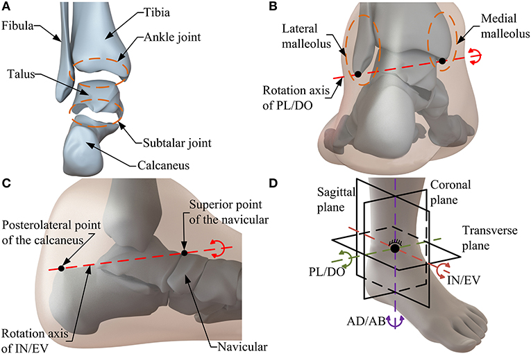
Figure 1. The HAC anatomy. (A) The structure of the HAC. (B) Rotation axis of PL/DO. (C) Rotation axis of IN/EV. (D) Motion form of the HAC.
According to the kinematic model of the HAC, a serial constraint branch (Figure 2A) with a three axes-intersected revolute joints (R1, R2, and R3) structure is selected as an equivalent spherical joint to imitate the 3-DOF rotational motion of the HAC and determine the rotation center of the robot. By using this constraint branch, the ankle rehabilitation treatment can be performed under a human-robot compatible situation with fixed rotation center and precise DOFs. Moreover, two identical non-constraint rods with UPS structure are selected as the kinematic branches. Based on the aforementioned consideration, a 2-UPS/RRR parallel mechanism is proposed as the basic configuration of the ankle rehabilitation robot. Joints P1, P2, and R1 are active, whereas all others are passive. For patients with ankle disabilities, the movement of the HAC becomes weaker and stiffer, and even with ankle spasticity/contracture (Zhou et al., 2014). Thus, to protect the already fragile ankle from secondary injury, the position of the shank and the HAC should remain stationary with respect to the foot. Additionally, a follow-up shank makes it difficult to perform treatment at the extreme position of the HAC, thus affecting the full recovery of function. By inverting the 2-UPS/RRR parallel mechanism (i.e., the base is positioned above the moving platform), and inserting the shank of the patient into the mechanism as a part of the base via an accessory wearable binding mechanism, decoupled foot-shank motion (i.e., the shank will not move with the foot) and the maximum safety guarantee can be achieved during different treatment modes.
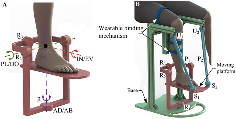
Figure 2. (A) Constraint branch. (B) Human-robot system.
The formed human-robot system consisting of the HAC and the wearable parallel robot is presented in Figure 2B. Analogous to the known Tricept mechanism, two unconstrained UPS branches provide six DOFs to the moving platform while three constraint force line vectors that through one point in space are acted in the platform wrench system via the properly constrained RRR branch, and thus retain three rotational ones of six DOFs. The line graph of the constraint spaces and freedom spaces of the branches and moving platform is presented in Table 1 based on Grassmann line geometry, in which the green solid lines, green solid double arrow lines, and blue dotted lines indicate the rotational DOF, translational DOF, and constraint force, respectively.
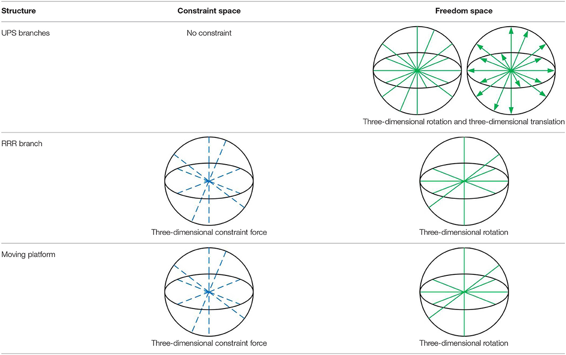
Table 1. Line graph of the constraint spaces and freedom spaces.
The K-G formula (Huang et al., 2013) is used to verify the number of DOFs obtained from the aforementioned analysis. The wearable parallel robot consists of a base, a moving platform, a constraint branch and two kinematic branches:
where F is the DOFs of the robot, n indicates the number of links included in the frame, g represents the number of joints, and fi is the DOFs permitted by joint i.
Since n = 6, g = 7, Σ fi= 15 (the robot contains three spherical joints, two universal joints and two prismatic joints), the DOFs of the parallel mechanism can be obtained by equation 1 as F = 3.
Kinematic Analysis
The schematic diagram of the parallel robot is presented in Figure 3. Several reference frames, i.e., O-xoyozo, O-xpypzp, Bi-xi1yi1zi1, Bi-xi2yi2zi2, and Ai-xi3yi3zi3, are established. Reference frames O-xoyozo and O-xpypzp (Figure 3A), which attached to rotation center O of the moving platform, are the base frame and the moving platform frame, respectively. These two reference frames are parallel in their initial configurations. As shown in Figure 3B, a local fixed reference frame Bi-xi1yi1zi1 (i = 1, 2) and a movable reference frame Bi-xi2yi2zi2 (i = 1, 2) are both assigned at the center Bi of joint Ui. Axes xi1, yi2, zi2 are collinear to the two revolute axes (ri1 and ri2) of joint Ui and the lower link of the kinematic branch, respectively. In the set-up configuration, the axis yi1 coincides with the axis ri2 of joint Ui, and initial angles appear between the frames Bi-xi1yi1zi1 and Bi-xi2yi2zi2. Moreover, reference frame Ai-xi3yi3zi3 (i = 1, 2) in joint Si location is assigned at the center Ai, and the directions of its three coordinate axes coincide with those of the frame Bi-xi2yi2zi2. In this paper, due to the three rotational DOFs of the wearable parallel robot, the posture of the moving platform can be described by its orientation with respect to the base.
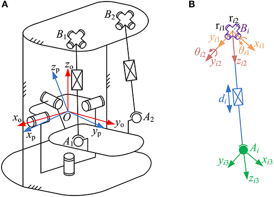
Figure 3. Parametric description of (A) the robot and (B) kinematic branch.
Considering the characteristics of the constraint branch, the Z-X-Y typed Euler angles can be utilized to express the orientation of the moving platform. The angles rotating about axis zp (AD/AB), axis xp (PL/DO) and axis yp (IN/EV) are denoted as γ, α, and β, respectively. The transformation from reference frame O-xpypzp to O-xoyozo, denoted as matrix Rop, is given as:
Inverse Position Solution
The inverse kinematics problem posed by a parallel mechanism is easy to manage (Li et al., 2018), in which a desired posture of the moving platform is given, and the drive variables can be calculated to achieve this task.
The coordinates of point Ai (i = 1, 2) can be computed simultaneously as follows:
where °Ai and pAi are the position vector of point Ai with respect to reference frames O-xoyozo and O-xpypzp, respectively. °Bi (i = 1, 2) denotes the position vector of point Bi expressed in reference frame O-xoyozo. di is the displacement of joint Pi, whereas zi2 is the direction vector of axis zi2. The transformation matrix Ro2 that transfers the coordinates from reference frame O-xoyozo to Bi-xi2yi2zi2 can be expressed as follows:
where Ro1 and R12 represent the transformation matrices between reference frames O-xoyozo and Bi-xi1yi1zi1, Bi-xi1yi1zi1, and Bi-xi2yi2zi2, respectively, and are given as follows:
where θi1 and θi2 denote the rotation angles of joint Ui around axes ri1 and ri2, respectively.
By substituting the first half of Equation (4) into Equation (3), individual limb length di can be mathematically expressed as follows:
The rotation angle θ3 around axis R1 can be simply obtained as:
Equations (7) and (8) give the inverse position solution of the robot.
Substituting the second half of Equation (4) into Equation (3), and using Equations (5–7), the following equation can be derived:
Let ki1, ki2, ki3 indicate the three components of the left vector in equation 9, the following equations can be obtained as follows:
Velocity Jacobian Matrix
According to the schematic diagram of the robot presented in Figure 3, the velocity vector VAi of center Ai can be written as:
where ω indicates the angular velocity of the moving platform.
Projecting the velocity vector VAi onto the reference frame Ai-xi3yi3zi3 leads to:
where , , and denote the direction vectors of axes xi3, yi3, and zi3, respectively, and can be written as follows:
where xi2, yi2, and zi2 represent the respective direction vectors of axes xi2, yi2, and zi2.
The velocity of the linear actuator can be calculated based on the structural feature of the kinematic branch as:
where Vzi3 indicates the velocity component of VAi in the axis zi3 direction, ḋi is the linear velocity of joint Pi. Moreover, coefficient matrix Q of VAi can be derived as follow:
The angular velocity can be simply obtained as follows:
Combining Equation (14) and Equation (16), the velocity mapping relationship between active joint space and task space can be expressed as follows:
where Jo is the original velocity Jacobian matrix of the robot.
Notably, the input end contains two linear motions and one rotational motion, while the output end consists exclusively of rotational motions (i.e., the velocity Jacobian matrix is dimensionally inhomogeneous). Thus, a non-dimensional form (Angeles, 1992) of the homogeneous Jacobian matrix Jv is required to be introduced:
where:
where is the position vector of point Ai with respect to the reference frame O-xpypzp, expressed in non-dimensional form. A scalar rsp indicates the distribution radius of the spherical joint with respect to the moving platform and is utilized to homogenize the original velocity Jacobian matrix (Zanganeh and Angeles, 1997). k* represents the scaling factor between the linear motion and rotational motion (generally, k*= 1).
Performance Indices
Reachable Workspace Index
The reachable workspace of an ankle rehabilitation robot must contain the ROM of the HAC summarized (Siegler et al., 1988) in Table 2. Meanwhile, to ensure that the safety issue will not occur in the process of treatment, the maximum allowable workspace (MAW) of the ankle rehabilitation robot should be constrained in a certain range (Table 2). By using the numerical searching method based on derived inverse position solution while considering the stroke constraint of the linear actuator, the feasible points in the reachable workspace of the ankle rehabilitation robot with certain dimension parameters can be obtained, and then the set of the reachable points forms the overall workspace. To evaluate the workspace, a reachable workspace index IRW can be written as follows:
where vRWand vMAW are the volume of the reachable workspace and the MAW, respectively, Δα, Δβ, and Δγ denote the ranges between the minimum and maximum α, β, and γ, respectively, which can be given as follows:
where αmax, αmin, βmax, βmin, γmax, and γmin can be obtained according to Table 2. The IRW can reach values from 0 to 1. The value is equal to 1 (or 0) mean that the robot possesses the largest (or smallest) workspace.
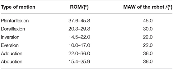
Table 2. ROM of the HAC and MAW of the robot.
Motion Isotropy Index
The inverse value of the condition number of robot's velocity Jacobian matrix, ranges between 0 and 1 (denote singular and isotropic configuration, respectively), is an important local performance index to evaluate the motion isotropy in one posture or over its full workspace of a parallel robot (Wu et al., 2013; Enferadi and Nikrooz, 2017). Its physical meaning can be expressed as a velocity ellipsoid and define as Equation (26). For a rehabilitation device, as many areas as possible in the reachable workspace are desired to possess relatively uniform motion isotropy. That is, condition number's inverse value of most of the feasible points should be closer to 1. To measure the global behavior of the condition number of the robot, a motion isotropy index IMI can be presented via computing the average of the inverse value of the condition number within the reachable workspace, and is written as follows:
where ; w denotes the reachable workspace of the ankle rehabilitation robot; ηJ is a local index indicating the inverse value of the condition number of robot's velocity Jacobian matrix in a given posture within the reachable workspace; lvlp and lvsp are the lengths of the long and short principal axes of the velocity ellipsoid, respectively. The value range of the IMI is between 0 and 1, and the value of which is desired to be larger.
Force Tansfer Index
As a human-robot system for ankle rehabilitation, the force is required to be transferred from robot's active joint space to patient's ankle space as sufficient torque which is an important condition for an ankle rehabilitation robot to achieve passive/active treatment. A force unit sphere fTf ≤ 1 is set up in active joint space. Subsequently, this sphere can be transferred into task space as a force ellipsoid via the force mapping relationship, and can be defined as follows:
where and ; f 1 and f 2 are the driving forces of joints P1 and P2, and τ3 is the driving torque of joint R1; τα, τβ, and τγ indicate the torques applied on the axes of PL/DO, IN/EV, and AB/AD, respectively; Jf denotes the force Jacobian matrix, and is the transpose of Jacobian matrix Jv.
The robot possesses a better (or worse) force transfer performance along a particular operation direction when the length of the force ellipsoid's radius along the directional vector is longer (or shorter). Moreover, the long (or short) principal directions of the force ellipsoid means the greatest (or least) force transfer performance. Thus, the length lfsp of the short principal axis of the force ellipsoid can be regarded as a local evaluation index of force transfer performance, and the corresponding global force transfer index IFT is given as follows:
Maximum Torque Index
To evaluate the force capability of the ankle rehabilitation robot while considering the real physical capability of robot's actuators, a set Tτ (or convex polyhedrons) of allowable forces and torques of the actuators should be defined based on the force Jacobian matrix in the task space. The radius ris of the inscribed sphere contained in the set indicates the largest real torque that can be realized by the ankle rehabilitation robot along all directions in the ankle space, i.e., this radius reflects the maximum torque in a given posture. According to the aforementioned analysis and the force mapping relationship, the set Tτ, and a global maximum torque index IMT of the ankle rehabilitation robot can be written as follows:
where Tτ is the generalized set of torques in the ankle space; Tf is the allowable forces and torques of the actuator; lris is a local index denoting the length of the ris, and is actually a local performance index. Without loss of generality, the force and torque limits of the driven system are assumed to be f 1max = f 2max = τ3max = 1. Thus, the IMT ranges from 0 to 1, a larger (or smaller) value of IMT indicates a better (or worse) force capability of the ankle rehabilitation robot.
Results
Mechanical Design
Based on the proposed kinematic configuration (i.e., 2-UPS/RRR parallel mechanism) and wearable design concept, the mechanical design of the wearable parallel robot (Figure 4) is detailed. Two sub-systems, i.e., a basic machine-drive system and a multi-model position/force data collection system, constitute the whole physical system of the robot.
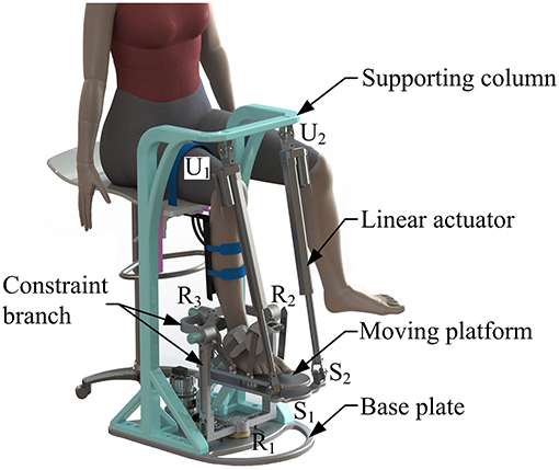
Figure 4. Wearable parallel robot.
The machine-drive system exhibits a parallel main structure, in which two kinematic branches and one constraint branch both connect the base to the moving platform. The base consists of a base plate and a supporting column. An adjustable lower-limb binding mechanism is established between the supporting column to maintain the stability of the lower-limb during rehabilitation and accommodate patients with different body sizes (Figure 5), double linear guide rails with double-slider, single-connection platform and locking function are employed to fix the thigh and adjust the up/down position of the patient, while the calf is fixed by a special leg holder and its forward/backward position can be fine-tuned by single linear guide rail with single-slider and locking function. Subsequently, the base and two identical kinematic branches are connected via the joint U1 and U2. Two linear actuators (CAHB-10, SKF, Sweden) are employed as joint P1 and P2 to adjust the lengths of the kinematic branches from 413 to 713 mm. As illustrated in Figure 6, joint S1 (S2) that located below the joint U1 (U2), and P1 (P2) is equivalent to a universal joint and a revolute joint with three axes intersecting at the same point, this combination design can reduce the cost and realize free-interference on workspace. Moreover, by loosening the screw bolt connecting the lower end of the linear actuator and joint S1 (S2), the kinematic branches can be separated from the constraint branch (i.e., the 2-UPS/RRR parallel robot is translated into an RRR serial robot). As shown in Figure 7, three lockable binding bands secure the patient's foot to the upper part of the moving platform (i.e., the upper platform) without large misalignment during combined motion. In addition to joint S1 and S2, the lower platform is also connected to joint R3 via an “L” shaped frame. As the active vertical-revolute joint of the constraint branch, joint R1 is driven by a servo motor (Figure 8), i.e., the combination of a frameless motor (KBM, Kollmorgen, America) and an incremental encoder (HKT30-301, REP, China), and is transmitted via a harmonic reducer (CSG-17-100, HarmonicDrive, Japan). Notably, the distance between the moving platform and the base plate determines the height of the patient's seat, and a higher seat may produce fear emotions that lead to negative treatment results on patient. Thus, to reduce the height of the moving platform, the axis R1 and its driving unit (i.e., the servo motor and the incremental encoder) are arranged in parallel and are connected to each other by a synchronous belt with a 1:1 reduction ratio. Additionally, as shown in Figure 8, screw bolts are installed as mechanical limits on joint R1, and two suspended revolute joints (i.e., joints R2 and R3) for safety. As mentioned above, the limits for the rotation angles are set according to the MAW in Table 2, and the maximum allowable angles of the PL/DO (αmax/αmin), IN/EV (βmax/βmin), and AD/AB (γmax/γmin) are set at 45°/30°, 22°/22°, and 36°/36° to ensure that the robot is suitable for both the left and right foot.
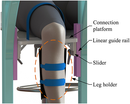
Figure 5. Lower-limb binding mechanism.
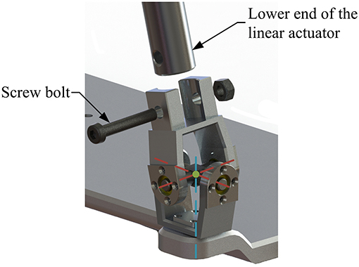
Figure 6. Joint S1 (S2).
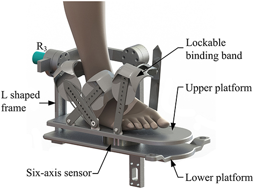
Figure 7. Moving platform.
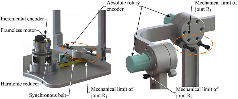
Figure 8. Mechanical limits, joint R1 and absolute rotary encoders.
A multi-model position/force data collection system is installed in the robot to realize various rehabilitation strategies, including ROM treatment based on position control, strength treatment based on impedance control and proprioceptive treatment base on intention recognition. Specifically, as illustrated in Figure 8, three absolute rotary encoders (HAN28U5, China) are arranged to measure the rotation angles of joints R1, R2, and R3 (i.e., real-time position information of the moving platform); two of them are connected in series with joints R2 and R3, as shown in the detailed view (Figure 9), joints R2 and R3 possess similar structure: the base, “C” shaped frame#1, “C” shaped frame#2, and “L” shaped frame are arranged in sequence, the latter rotates with respect to the former, and the “L” shaped frame drives the moving platform together with the “V” shaped part of the lower platform; another one is placed on the base plate and arranged in parallel with joint R1. Additionally, the force/torque information of the rehabilitation process, i.e., the interaction force and torque between the foot and moving platform, can be collected by a six-axis sensor installed between the upper and lower platform (Figure 7). In general, the encoders and sensor form a complete information collection system, which can produce real-time feedback in the process of treatment and lay a foundation for various control schemes and rehabilitation strategies.
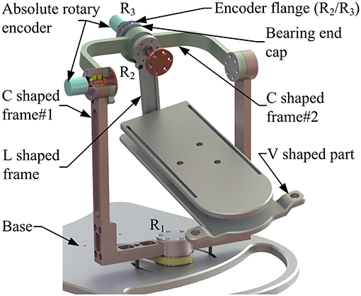
Figure 9. Detailed view of joints R2 and R3.
Performance Evaluation
The geometrical parameters of the wearable parallel robot are presented in Table 3, where the absolute values of the coordinates of joint Ui are expressed with respect to reference frame O-xoyozo, the absolute values of the coordinates of joint Si are expressed with respect to reference frame O-xpypzp.
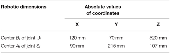
Table 3. The geometrical dimensions of the robot.
The reachable workspace (the set of the solid points) of the wearable parallel robot is calculated in Figure 10A. For this robot, the constraint condition is the stroke constraint of the linear actuators and the arrangement of the mechanical limits. According to the calculation results, the appearance of the reachable workspace is a cube, suggesting that the robot can reach any posture in MAW, i.e., the volume of the reachable workspace is equal to that of the MAW, and thus IRW = 1. Additionally, when the mechanical limits are removed, the workspace of the robot is represented by a high transparency shadow (Figure 10A) which covers the set of the solid points, indicating that the mechanical limits can effectively restrict the workspace to a safe range.
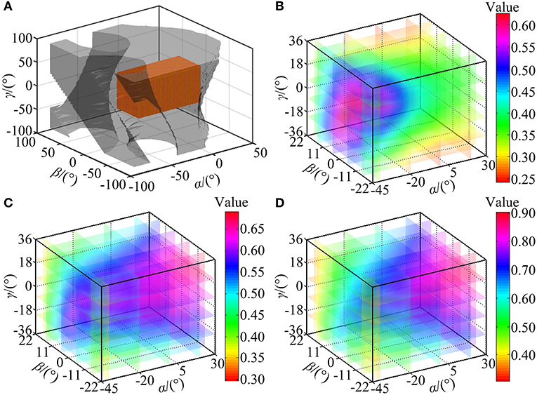
Figure 10. Performance indices calculation. (A) The reachable workspace of the robot. (B) Trend in value of ηJ. (C) Trend in value of lfsp. (D) Trend in value of lris.
The ηJ, lspa, and lris are evaluated within the calculated reachable workspace. Subsequently, trends of their corresponding values are illustrated in Figures 10B–D, respectively, with values represented by the color map shown in the color bar and trends represented by the color variation in the color map. The distribution volume proportions of the corresponding values in the reachable workspace are shown in Figures 11A–C, while the proportion that indices ηJ, lfsp, and lris superior to indices IMI, IFT, and IMT is shown in Figure 11D.
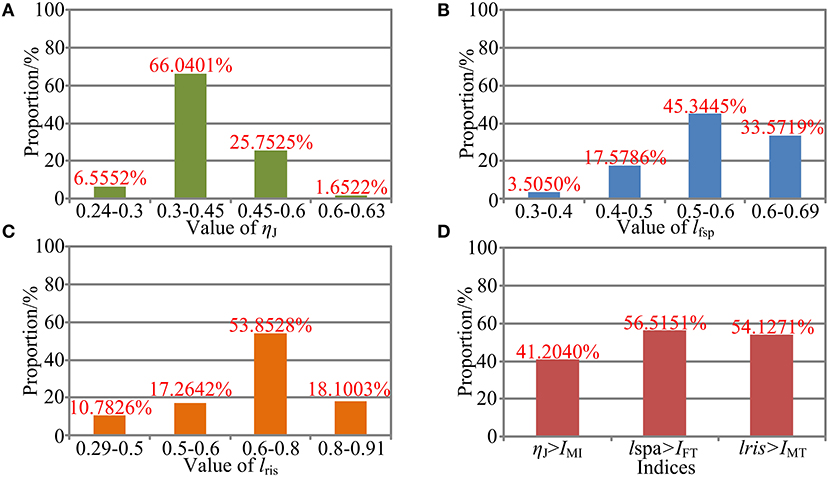
Figure 11. Performance evaluation. (A) Performance distribution of ηJ. (B) Performance distribution of lfsp. (C) Performance distribution of lris. (D) Performance comparison between the local indices and the global indices.
As shown in Figure 10B, the values of ηJ change smoothly with no mutation within overall reachable workspace, indicating that the robot has no singularity configuration. Moreover, the robot exhibits better motion isotropy performance in the central part of the reachable workspace, since the values of the ηJ are relatively small in the boundary area and increases gradually toward the central section. As shown in Figure 11A, the value of ηJ is mainly distributed between 0.3 and 0.6, and the minimum value, varies from 0.24 to 0.3, accounted for 6.5552% in the reachable workspace. Thus, the robot is sufficiently kinematically isotropic for ankle rehabilitation.
Analogous to ηJ, both lfsp and lris possess better performance in the central part (Figures 10C,D). As illustrated in Figures 11B,C, the values of lfsp and lris are mainly distributed between 0.5 and 0.69, 0.6, and 0.91, respectively. Moreover, the proportions of the worst-performing postures of lfsp and lris are 3.5050 and 10.7826%. Thus, the robot possesses high force transfer performance and large maximum torque performance, especially in the central part.
The values of IMI, IFT, and IMT are calculated as IMI = 0.5573, IFT = 0.5565, and IMT = 0.6744, demonstrating sufficient global performances. As shown in Figure 11D, the proportion of ηJ, lfsp, and lris exceeded IMI, IFT, and IMT in magnitude are 41.2040, 56.5151, and 54.1271%, mainly located in the central section (i.e., main treatment area), suggesting that most postures within the reachable workspace are well-performed enough (although the proportion of ηJ superior to indices IMI is failure to reach 50%, most postures that do not meet the condition exceed 0.5 in magnitude, as shown in Figure 10B).
To verify the calculation correctness and obtain a detailed view, velocity ellipsoids, force ellipsoids, sets Tτ and their inscribed spheres in two stochastic configurations ([α = −30°, β = 20°, γ = 5°], [α = 10°, β = −10°, γ = −2°]) of the reachable workspace are provided in Figure 12. Figures 12A–D report that due to the duality between the velocity ellipsoid and the force ellipsoid (Chiu, 1988), the principal axial directions of the two ellipsoids are coincident and the lengths, i.e. lvsp and lflp (the length of the long principal axis of the force ellipsoid), lvlp and lfsp, are reciprocal. Index ηJ are calculated as 0.4081 and 0.3866 in these two configurations, while index lspa are obtained as 0.4477 and 0.6153, respectively. Figures 12E,F indicate that the cube in active joint space maps to an irregular polyhedron in task space with an inscribed sphere tangent to the colored surfaces, and index lris are, respectively calculated as 0.4790 and 0.7797.
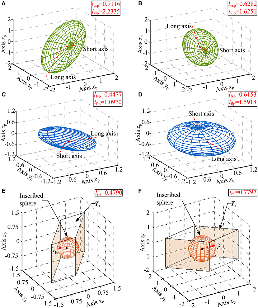
Figure 12. (A,B) Velocity ellipsoids, (C,D) force ellipsoids, (E,F) sets Tτ and their inscribed spheres for [α = −30°, β = 20°, γ = 5°], [α = 10°, β = −10°, γ = −2°] configurations.
Discussions
We introduced a novel robot with the features of a wearable design concept and parallel platform-based form. The salient advantages of this robot are its simple configuration and safety guarantee. Moreover, we evaluated and analyzed the performance of this robot within the overall reachable workspace. Results showed that the proposed robot possesses sufficient motion isotropy, high force transfer performance and large maximum torque performance.
In comparison with the ankle rehabilitation robot applying redundant actuation, by adopting a simple kinematic configuration (i.e., 2-UPS/RRR parallel mechanism) as the main mechanical structure, actuator non-redundancy and easy operation can be realized on this wearable parallel robot, and then the cost of the robot manufacturing, the difficultly of the control system development, and the burden of the therapists can also be effectively reduced. Additionally, according to the performance evaluation and analysis, the proposed robot satisfies the conditions of performing ankle rehabilitation treatment for patients.
This wearable parallel robot is designed with several safety precautions to protect the patients from secondary injury in the process of treatment. Specifically, this robot possesses the lowest moving platform under the premise of meeting the ROM requirement, and then correspondingly reduces the height of the patient's seat. An excessively high seat increases the risk of injury and easily results in patients' contravene mood. Moreover, the arrangement of the lower-limb binding mechanism and three lockable binding bands, respectively fix the thigh/calf and the foot with the base and the moving platform. With this wearable design concept, the foot moves in the form of platform-base with respect to the lower-limb, and thus avoiding the coupled foot-shank motion. Additionally, the supporting column is narrow in width to allow the patient to place the non-rehabilitation leg conveniently. Demountable mechanical limits are implemented to constrain the workspace of the robot in a safe range.
In terms of information collection, the proposed robot is equipped with multi-model position/force data collection system containing a six-axis sensor and three absolute rotary encoders. Based on the collected kinematic and dynamic information, passive treatment mode and active treatment mode can be achieved. By separating the spherical joint from the upper end of the linear actuators, the 2UPS/RRR parallel robot can be translated into an RRR serial robot. Therapists can bind the patient's foot on the moving platform in advance and plan the treatment trajectory by manually moving the RRR serial robot according to the joint characteristics and the severity of impairment among different patients. The trajectory can be recorded by the three absolute rotary encoders, and the robot can provide repetitive treatment on the basis of this trajectory.
It should be highlight that the indices are not applied to design the geometrical parameters of the mechanism in this study. A low height of the moving platform, a narrow width of the overall mechanism and a sufficient volume of the reachable workspace are more considered at current stage. Moreover, by applying the transmission angular theory and screw theory to evaluate the motion/force transmissibility (i.e., essential function) of the parallel mechanism, a more convincing kinematic performance evaluation system (Liu et al., 2008; Wu et al., 2010, 2011; Xie et al., 2010) was proposed compared with the utilization of the Jacobian matrix in evaluation of parallel mechanism. Based on the defined motion/force transmission indices, dimensional synthesis (optimal design) was also carried out using performance charts. In future studies, dimension optimal design according to the aforementioned method will be carried out before prototype construction. Additionally, based on the multi-model position/force data collection system, future work could go in the direction of the development of the control schemes to achieve various rehabilitation protocols.
Conclusion
This paper presented a novel wearable parallel robot for ankle rehabilitation in which the intended simple configuration is determined according to the HAC anatomy and safety consideration. Based on the performance evaluation, the proposed robot possesses relatively uniform motion isotropy, high force transfer performance and large maximum torque performance within a large reachable workspace. Equipped with a multi-model position/force data collection system, both passive and active treatment mode can be achieved. And the robot has the potential to be used for the rehabilitation treatment of ankle disabilities.
Data Availability Statement
The datasets analyzed in this article are not publicly available. Requests to access the datasets should be directed to dongmj@bjut.edu.cn.
Author Contributions
SZ and JL conceived and designed this study. SZ, XZ, WF, and YK performed the mechanical design and performance evaluation. SZ wrote the paper. MD reviewed and edited the manuscript. JL also made a contribution to the edition of the manuscript. All authors had read and approved the manuscript.
Funding
This work was supported by the National Key R&D Program of China under Grant No. 2018YFB1307004, the National Natural Science Foundation of China under Grant Nos. 51675008, 61903011, and 51805025, the Beijing Natural Science Foundation under Grant Nos. 3171001, 3204036, and 17L20019, Natural Science Foundation of Beijing Education Committee (No. KM202010005021), and Beijing Postdoctoral Research Foundation (Q6001002201901).
Conflict of Interest
The authors declare that the research was conducted in the absence of any commercial or financial relationships that could be construed as a potential conflict of interest.
References
Angeles, J. (1992). The design of isotropic manipulator architectures in the presence of redundancies. Int. J. Robot. Res. 11, 196–201. doi: 10.1177/027836499201100303
Blaya, J. A., and Herr, H. (2004). Adaptive control of a variable-impedance ankle-foot orthosis to assist drop-foot gait. IEEE Trans. Neural Syst. Rehabil. Eng. 12, 24–31. doi: 10.1109/TNSRE.2003.823266
Boehler, A. W., Hollander, K. W., Sugar, T. G., and Shin, D. (2008). “Design, implementation and test results of a robust control method for a powered ankle foot orthosis (AFO),” in 2008 IEEE International Conference on Robotics and Automation (ICRA) (Pasadena, CA), 2025–2030. doi: 10.1109/ROBOT.2008.4543504
Chiu, S. L. (1988). Task compatibility of manipulator postures. Int. J. Robot. Res. 7, 13–21. doi: 10.1177/027836498800700502
Dai, J. S., and Zhao, T. (2004). Sprained ankle physiotherapy based mechanism synthesis and stiffness analysis of a robotic rehabilitation device. Auton. Robots 16, 207–218. doi: 10.1023/B:AURO.0000016866.80026.d7
Dettwyler, M., Stacoff, A., Quervain, I. A. K., and Stussi, E. (2004). Modeling of the ankle joint complex. Reflections with regards to ankle prostheses. Foot Ankle Surg. 10, 109–119. doi: 10.1016/j.fas.2004.06.003
Dijk, W. V., Meijneke, C., and Kooij, H. V. D. (2017). Evaluation of the Achilles ankle exoskeleton. IEEE Trans. Neural Syst. Rehabil. Eng. 25, 151–160. doi: 10.1109/TNSRE.2016.2527780
Dul, J., and Johnson, G. E. (1985). A kinematic model of the human ankle. J. Biomed. Eng. 7, 137–143. doi: 10.1016/0141-5425(85)90043-3
Enferadi, J., and Nikrooz, R. (2017). The performance indices optimization of a symmetrical fully spherical parallel mechanism for dimensional synthesis. J. Intell. Robot. Syst. 90, 305–321. doi: 10.1007/s10846-017-0675-6
Erdogan, A., Celebi, B., Satici, A. C., and Patoglu, V. (2017). AssistON-Ankle: a reconfigurable ankle exoskeleton with series-elastic actuation. Auton. Robot. 41, 743–758. doi: 10.1007/s10514-016-9551-7
Fan, Y., and Yin, Y. (2009). “Mechanism design and motion control of a parallel ankle joint for rehabilitation robotic exoskeleton,” in Proceedings of the 2009 IEEE International Conference on Robotics and Biomimetics (Guilin), 2527–2532. doi: 10.1109/ROBIO.2009.5420488
Ferris, D. P., Gordon, K. E., Sawicki, G. S., and Peethambaran, A. (2006). An improved powered ankle-foot orthosis using proportional myoelectric control. Gait Posture 23, 425–428. doi: 10.1016/j.gaitpost.2005.05.004
Feuerbach, J. W., Grabiner, M. D., Koh, T. J., and Weiker, G. G. (1994). Effect of an ankle orthosis and ankle ligament anesthesia on ankle joint proprioception. Am. J. Sport. Med. 22, 223–229. doi: 10.1177/036354659402200212
Girone, M., Burdea, G., and Bouzit, M. (1999). “The rutgers ankle orthopedic rehabilitation interface,” in ASME Haptics Symposium. Vol 67 (Nashville), 305–312.
Gordon, K. E., Sawicki, G. S., and Ferris, D. P. (2006). Mechanical performance of artificial pneumatic muscles to power an ankle-foot orthosis. J. Biomech. 39, 1832–1841. doi: 10.1016/j.jbiomech.2005.05.018
Hollander, K. W., Ilg, R., Sugar, T. G., and Herring, D. (2006). An efficient robotic tendon for gait assistance. J. Biomech. Eng. 128, 788–791. doi: 10.1115/1.2264391
Huang, Z., Li, Q., and Ding, H. (2013). Theory of Parallel Mechanisms. (Netherlands: Springer). doi: 10.1007/978-94-007-4201-7
Hussain, S., Jamwal, P. K., and Ghayesh, M. H. (2017). State-of-the-art robotic devices for ankle rehabilitation: mechanism and control review. Proc. Inst. Mech. Eng. Part H 231, 1224–1234. doi: 10.1177/0954411917737584
Isman, R. E., and Inman, V. T. (1969). Anthropometric studies of the human foot and ankle. Bull. Pros. Res. 11, 97–129.
Jamwal, P., Xie, S. Q., Hussain, S., and Parsons, J. (2014). An adaptive wearable parallel robot for the treatment of ankle injuries. IEEE/ASME Trans. Mech. 19, 64–75. doi: 10.1109/TMECH.2012.2219065
Khalid, Y., Gouwanda, D., and Parasuraman, S. (2015). A review on the mechanical design elements of ankle rehabilitation robot. J. Eng. Med. 229, 452–463. doi: 10.1177/0954411915585597
Kim, J., Hwang, S., Sohn, R., Lee, Y., and Kim, Y. (2011). Development of an active ankle foot orthosis to prevent foot drop and toe drag in hemiplegic patients: a preliminary study. Appl. Bionics Biomech. 8, 377–384. doi: 10.1155/2011/530375
Kinnaird, C. R., and Ferris, D. P. (2009). Medial gastrocnemius myoelectric control of a robotic ankle exoskeleton. IEEE Trans. Neural. Syst. Rehabil. Eng. 17, 31–37. doi: 10.1109/TNSRE.2008.2008285
Li, J., Li, S., Zhang, L., Tao, C., and Ji, R. (2018). Position solution and kinematic interference analysis of a novel parallel hip-assistive mechanism. Mech. Mach. Theory 120, 265–287. doi: 10.1016/j.mechmachtheory.2017.10.002
Liu, G., Gao, J., Yue, H., Zhang, X., and Lu, G. (2006). “Design and kinematics simulation of parallel robots for ankle rehabilitation,” in Proceedings of the 2006 IEEE International Conference on Mechatronics and Automation (Beijing), 253–258. doi: 10.1109/ICMA.2006.257780
Liu, X., Wu, C., and Wang, J. (2008). “A new index for the performance evaluation of parallel manipulators: a study on planar parallel manipulators,” in Proceedings of 7th World Congress on Intelligent Control and Automation (Chongqing), 353–357. doi: 10.1109/WCICA.2008.4592950
Lopez, R., Salazar, S., and Lozano, R. (2013). “Model and control of the elltio with two degrees of freedom,” in International Conference on System Theory, Control and Computing (Sinaia), 305–310. doi: 10.1109/ICSTCC.2013.6688977
Meijneke, C., Dijk, W. V., and Kooij, H. V. D. (2014). “Achilles: an autonomous lightweight ankle exoskeleton to provide push-off power,” in 2014 5th IEEE RAS&EMBS International Conference on Biomedical Robotics and Biomechatronics (São Paulo), 918–923. doi: 10.1109/BIOROB.2014.6913898
Meng, W., Liu, Q., Zhou, Z., Ai, Q., Sheng, B., and Xie, S. (2015). Recent development of mechanisms and control strategies for robot-assisted lower limb rehabilitation. Mechatronics 31, 132–145. doi: 10.1016/j.mechatronics.2015.04.005
Michmizos, K. P., Rossi, S., Castelli, E., Cappa, P., and Krebs, H. I. (2015). Robot-aided neurorehabilitaion: a pediatric robot for ankle rehabilitation. IEEE Trans. Neural Syst. Rehabil. Eng. 23. doi: 10.1109/TNSRE.2015.2410773
Nomura, K., Yonezawa, T., Ogitsu, T., Mizoguchi, H., and Takemura, H. (2015). “Development of stewart platform type ankle-foot device for trip prevention support,” in 2015 37th Annual International Conference of the IEEE Engineering in Medicine & Biology Society (Milan), 4808–4811. doi: 10.1109/EMBC.2015.7319469
Oymagil, A. M., Hitt, J. K., Sugar, T., and Fleeger, J. (2008). “Control of a regenerative braking powered ankle foot orthosis,” in Proceedings of the 2007 IEEE 10th International Conference on Rehabilitation Robotics (Noordwijk), 28–34. doi: 10.1109/ICORR.2007.4428402
Park, Y. L., Chen, B. R., Perez-Arancibia, N. O., Young, D., Stirling, L., Wood, R. J., et al. (2014). Design and control of a bio-inspired soft wearable robotic device for ankle-foot rehabilitation. Bioinspir. Biomim. 9:016007. doi: 10.1088/1748-3182/9/1/016007
Ren, Y., Wu, Y., Yang, C., Xu, T., Harvey, R. L., and Zhang, L. (2017). Developing a wearable ankle rehabilitation robotic device for in-bed acute stroke rehabilitation. IEEE Trans. Neural Syst. Rehabil. Eng. 25, 589–596. doi: 10.1109/TNSRE.2016.2584003
Roy, A., Krebs, H. I, Williams, D. J., Bever, C. T., Forrester, L. W., Macko, R. M., et al. (2009). Robot-aided neurorehabilitation: a novel robot for ankle rehabilitation. IEEE Trans. Robot. 25, 569–582. doi: 10.1109/TRO.2009.2019783
Saglia, J., Tsagarakis, N., Dai, J. S., and Caldwell, D. (2009). A high-performance redundantly actuated parallel mechanism for ankle rehabilitation. Int. J. Robot. Res. 28, 1216–1227. doi: 10.1177/0278364909104221
Sawicki, G. S., and Ferris, D. P. (2009). A pneumatically powered knee-ankle-foot orthosis (KAFO) with myoelectric activation and inhibition. J. Neuroeng. Rehabil. 6:23. doi: 10.1186/1743-0003-6-23
Shorter, K. A., Kogler, G. F., Loth, E., Durfee, W. K., and Hsiao-Wecksler, E. T. (2011). A portable powered ankle-foot orthosis for rehabilitation. J. Rehabil. Res. Dev. 48, 459–472. doi: 10.1682/JRRD.2010.04.0054
Siegler, S., Chen, J., and Schneck, C. (1988). The three-dimensional kinematics and flexibility characteristics of the human ankle and subtalar joints-part i: kinematics. J. Biomech. Eng. 110, 364–373. doi: 10.1115/1.3108455
Takemura, H., Onodera, T., Ding, M., and Mizoguchi, H. (2012). Design and control of a wearable steward platform-type ankle-foot assistive device. Int. J. Adv. Robot. Syst. 9:52449. doi: 10.5772/52449
Tsoi, Y., Xie, S. Q., and Graham, A. (2009). Design, modeling and control of an ankle rehabilitation robot. Des. Control Intell. Robot. Syst. 177, 377–399. doi: 10.1007/978-3-540-89933-4_18
Wang, C., Fang, Y., Guo, S., and Chen, Y. (2013). Design and kinematical performance analysis of a 3-RUS/RRR redundantly actuated parallel mechanism for ankle rehabilitation. J. Mech. Robot. 5:041003. doi: 10.1115/1.4024736
Wang, C., Fang, Y., Guo, S., and Zhou, C. (2015). Design and kinematic analysis of redundantly actuated parallel mechanisms for ankle rehabilitation. Robotica 33, 366–384. doi: 10.1017/s0263574714000241
Ward, J., Sugar, T., Boehler, A., Standeven, J., and Engsberg, J. R. (2011). Stroke survivors' gait adaptations to a powered ankle-foot orthosis. Adv. Robot. 25, 1879–1901. doi: 10.1163/016918611X588907
Witte, K. A., Zhang, J., Jackson, R. W., and Collins, S. H. (2015). “Design of two lightweight, high-bandwidth torque-controlled ankle exoskeletons,” in 2015 IEEE International Conference on Robotics and Automation (ICRA) (Washington, DC), 1223–1228. doi: 10.1109/ICRA.2015.7139347
Wu, C., Liu, X., Wang, L., and Wang, J. (2010). Optimal design of spherical 5R parallel manipulators considering the motion/force transmissibility. J. Mech. Design 132:031003. doi: 10.1115/1.4001129
Wu, C., Liu, X., Wang, L., and Wang, J. (2011). Dimension optimization of an orientation fine-tuning manipulator for segment assembly robots in shield tunneling machines. Autom. Constr. 20, 353–359. doi: 10.1016/j.autcon.2010.11.005
Wu, J., Li, T., Wang, J., and Wang, L. (2013). Performance analysis and comparison of planar 3-DOF parallel manipulators with one and two additional branches. J. Intell. Robot. Syst. 72, 73–82. doi: 10.1007/s10846-013-9824-8
Xie, F., Liu, X., Wang, L., and Wang, J. (2010). Optimal design and development of a decoupled A/B-axis tool head with parallel kinematics. Adv. Mech. Eng. 2, 1652–1660. doi: 10.1155/2010/474602
Yao, S., Zhuang, Y., Li, Z., and Song, R. (2018). Adaptive admittance control for an ankle exoskeleton using an EMG-Driven musculoskeletal model. Front. Neurorobot. 12:16. doi: 10.3389/fnbot.2018.00016
Yoshizawa, N. (2010). “Prototype active AFO with ankle joint brake for achilles tendon ruptures,” in 2010 3rd International Conference on Biomedical Engineering and Informatics (Yantai), 1775–1778. doi: 10.1109/BMEI.2010.5639889
Zanganeh, K., and Angeles, J. (1997). Kinematic isotropy and the optimum design of parallel manipulators. Int. J. Robot. Res. 16, 185–197. doi: 10.1177/027836499701600205
Zhang, M., Cao, J., Zhu, G., Miao, Q., Zeng, X., and Xie, S. Q. (2017). Reconfigurable workspace and torque capacity of a compliant ankle rehabilitation robot (CARR). Robot Auton. Syst. 98, 213–221. doi: 10.1016/j.robot.2017.06.006
Zhou, Z., Zhou, Y., Wang, N., Gao, F., Wei, K., and Wang, Q. (2014). A proprioceptive neuromuscular facilitation integrated robotic ankle-foot system for post stroke rehabilitation. Robot. Auton. Syst. 73, 111–122. doi: 10.1016/j.robot.2014.09.023
Keywords: ankle rehabilitation, parallel robot, mechanical design, performance indices, performance evaluation
Citation: Zuo S, Li J, Dong M, Zhou X, Fan W and Kong Y (2020) Design and Performance Evaluation of a Novel Wearable Parallel Mechanism for Ankle Rehabilitation. Front. Neurorobot. 14:9. doi: 10.3389/fnbot.2020.00009
Received: 29 August 2019; Accepted: 29 January 2020;
Published: 18 February 2020.
Edited by:
Li Wen, Beihang University, ChinaReviewed by:
Fugui Xie, Tsinghua University, ChinaWenyuan Liang, National Research Center for Rehabilitation Technical Aids, China
Copyright © 2020 Zuo, Li, Dong, Zhou, Fan and Kong. This is an open-access article distributed under the terms of the Creative Commons Attribution License (CC BY). The use, distribution or reproduction in other forums is permitted, provided the original author(s) and the copyright owner(s) are credited and that the original publication in this journal is cited, in accordance with accepted academic practice. No use, distribution or reproduction is permitted which does not comply with these terms.
*Correspondence: Mingjie Dong, dongmj@bjut.edu.cn