Far-Field Earthquake Responses of Overhead Line Equipment (OHLE) Structure Considering Soil-Structure Interaction
 Chayut Ngamkhanong
 Sakdirat Kaewunruen
 Charalampos Baniotopoulos
- 1Department of Civil Engineering, University of Birmingham, Birmingham, United Kingdom
- 2Birmingham Centre for Railway Research and Education, University of Birmingham, Birmingham, United Kingdom
Overhead line equipment (OHLE) is the components for the electric train which supply the electric power to the train. For one or two tracks, OHLE is normally supported by cantilever mast. The cantilever mast, which is made of H-section steel, is slender and has a poor dynamic behavior by nature. Nonetheless, the mast structures, which located alongside the railway track, have not been fully studied on the dynamic behavior. This paper presents the effects of far-field excitations on cantilever mast and overhead contact wire. The five far-field earthquake records at various magnitudes between 6.5 and 8 Mw are considered. A three-dimensional mast structure with varying support stiffness is made using finite element modeling. It is interesting that support stiffness plays a role in the dynamic responses of OHLE during far-field earthquakes due to the change of its properties. Surprisingly, the earthquakes can cause damage to the overhead contact wire which lead to the failure of electric system. In this case, the train cannot run until the broken wire and electric system is cleared. This occurs when there are the losses of support stiffness due to the failure of support connection or soil degradation. Moreover, beating phenomenon, which normally occurs in the tall building, is obviously observed in OHLE during the occurrence of earthquake. This is the world first to demonstrate the effects of far-field earthquakes on the cantilever mast structure and the response of OHLE. The insight in this earthquake response of OHLE and its support has raised the awareness of engineers for better design of cantilever mast structure and its support condition. The outcome of this study will provide a new earthquake detection method using OHLE.
Introduction
At present, railway infrastructure experiences harsh environments and aggressive loading conditions from increased traffic and load demands. Due to the rapid growth in population, the passenger journeys have increased by nearly 100% and freight by 60% (Baxter, 2015). The provided extra capacity is needed for the economic growth in the future (RailCorp, 2011a). Consequently, the electric train has become the efficient railway systems. The electric train is allowed to run frequently and quickly. Also, an electric train is cheaper than diesel train in terms of both construction and maintenance. For electric train, the overhead line equipment (OHLE) is an important asset of the railway infrastructure and is one of the most vulnerable ones. OHLE is an equipment to supply power to make electric trains move, as shown in Figure 1. The support of OHLE is cantilever mast or portal frame depending on the number of track. The cantilever mast, which is normally made of H-section steel column, is a support of OHLE for only one or two tracks. Although the concept of OHLE is simple, the problem is poor dynamic behaviors of OHLE are needed to develop (Beagles et al., 2016). Due to the extreme environmental events and severe periodic force, such as an earthquake, in surrounding area may cause damage to the track and OHLE structure especially mast structure, this can lead to the failure of the electrical system (Shing and Wong, 2008; Robinson and Bryan, 2009; Taylor, 2013). Therefore, the dynamic behaviors of cantilever mast structure and its monitoring system are needed to take into account during train operation and the occurrence of extreme environmental events. Although the effects of ground borne vibration generated by passing train on cantilever mast have been studied (Kurzeil, 1979; Madshus et al., 1996; Jonsson, 2000; Kouroussis et al., 2013, 2014, 2015; Vogiatzis and Mouzakis, 2017), the effects of earthquake have not been introduced.
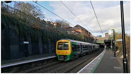
Figure 1. Electric train and overhead contact wire on West Midland railway line, UK.
Based on a review of open literature, far-field earthquakes on seismic responses of SDOF system with considering soil-structure interaction have been studied (Davoodi and Sadjadi, 2015). In addition, the responses of building under far-field earthquake have been investigated as can be seen in many studies (Ngamkhanong and Pinkaew, 2015). It was noted that large structures or high rise buildings were more affected due to the long duration and narrow band nature of far-field excitation. Resonance phenomenon is the effect occurred when the frequency of ground motion matches the natural frequency of a structure. It will suffer the damage and large oscillations. Even though the cantilever mast structure is the small structure compare to the building, this structure may experience the resonance effect due to the adaptation of soil and support conditions beneath the structure which leads to the change of its properties. In practical work, the structures are designed with the assumption of having fixed support. In fact, there is a small displacement created by the supporting soil. Based on the revealed literature (NEHRP Consultants Joint Venture, 2012; Prum and Jiravacharadet, 2012), different soil support conditions were taken into account. It was noted that soil-structure interaction affected the overall response of the structure. As for mast structure, it was noticeable that the rotational stiffness affected the natural frequencies and mode shape of vibration in a lower mode but rarely affected the fundamental mode in a higher mode (Ngamkhanong et al., 2017). This was because the dynamic behavior was characterized by coincident eigenfrequencies, mode order change, while the eigenfunctions remain associated with the corresponding eigenvalues (Pierre, 1988; Benedettini et al., 2009; Sari et al., 2017). In addition, soil-structure interaction has a crucial influence on the seismic response of structures especially founded on soft soils (Davoodi and Sadjadi, 2015).
The present paper aims to present a new study into the effect of far-field earthquakes on mast structure and overhead line equipment (OHLE) taking into account its underlying soil properties. Finite element model is employed to calculate the structural responses. The five far-field ground motion records with the magnitude of 6.5–8 Mw and the distance greater than 150 km were extracted from PEER Strong Motion Database. The obtained simulation results reveal that the support condition, earthquake magnitude, and its characteristics influence on the dynamic responses of mast structure. The insight in the earthquake response of overhead line equipment and its support has raised the awareness of engineers for better design of cantilever mast structure. The outcome of this study is to propose the possibility of using OHLE for earthquake detection.
Methodology
Modeling
In this study, the 3-dimensional finite element modeling is considered using a general-purpose finite element package STRAND7 (G+D Computing, 2001). OHLE is normally supported from cantilever masts, typically made of H-section steel, with a fixed base. The catenary cable and the pull/push-off arms supporting the contact wire are attached to the ends of the cantilever. The modeling of mast structure is shown in Figure 2, where consist of the two force member only. The young modulus of steel is 2 × 10⁵ MPa with the density of 7850 kg/m3. Poisson's ratio is 0.25.
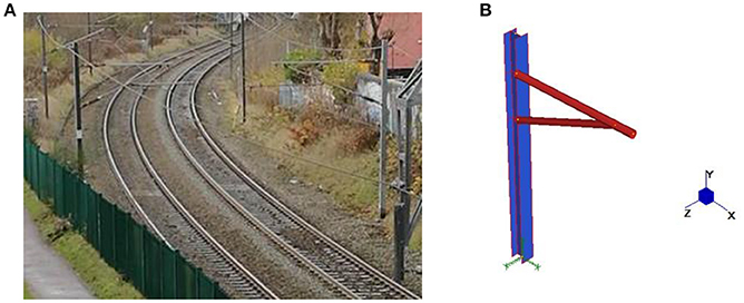
Figure 2. (A) OHLE for double tracks and (B) 3-D modeling.
In this study, support condition is taken into account. Figures 3A,B show the support condition of cantilever mast and frame mast, respectively, which are the embedded steel to foundation connection. The translational stiffness in three directions is assumed to be fixed in order to restraint the translation displacement. Based on soil and support conditions, although translational stiffness, denoted by kx and ky in is not taken into account, the rotational stiffness, denoted by kzz in Figure 3C, of support conditions is varied from 100 kNm/rad to infinite value (fully fixed support or rigid soil). The schematic load to structure and its base support is shown in Figure 3C.
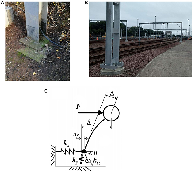
Figure 3. Support of (A) cantilever mast (B) frame mast and (C) Schematic load to structure with rotational flexibility at support.
It should be noted that the change of soil-structure interaction leads to the decrease in the natural frequency as tabulated in Table 1 and have more flexible compared to the corresponding structure supported by rigid soil or fully fixed support. The rotational support stiffness relates to the ability of connection to resist moment and curvature (in general, hinge support is 0 and fixed support is the infinity). It is noted that the support stiffness depends on the quality of connection and soil condition. The viscoelastic model of soil is adopted in this study.
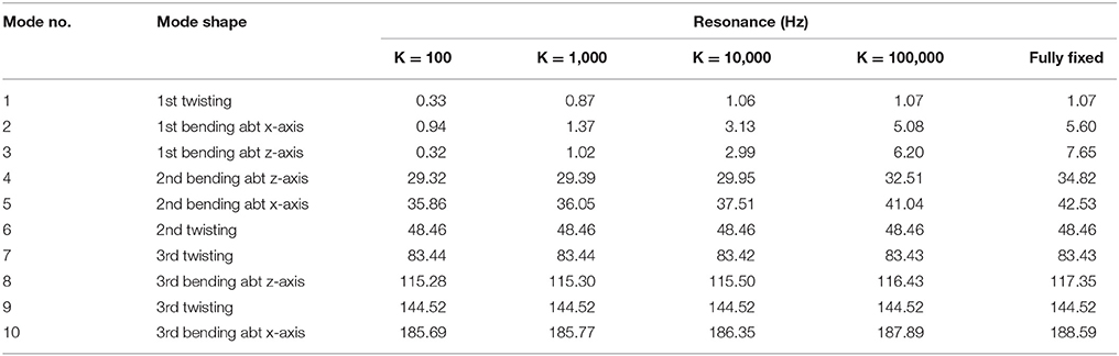
Table 1. Mode shape and natural frequency of cantilever mast at various soil stiffness in kNm/rad (Ngamkhanong et al., 2017).
Far-Field Earthquake Excitations
The 5 far-field earthquake records from PEER ground motion database having moment magnitudes (Mw) of 6.5–8.0 and the distance greater than 150 km are considered as shown in Table 2. The response spectra of earthquakes in the frequency domain are shown in Figure 4. Generally, the earthquakes recorded have two directions (N-S and E-W). However, the only stronger direction of the earthquake is used as an inputted earthquake. It should be noted that the frequencies of earthquakes in both directions are nearly the same. As expected, the critical case that causes higher response is in the longitudinal direction to the track because the first two fundamental modes are twisting and bending about transverse (X-axis). However, firstly, both directions are considered because the sensitivity of soil stiffness, that causes the change in natural frequency and mode of vibration, is taken into account. It is noted that the earthquakes used are scaled up to match the predicted ground motions in Bangkok, Thailand.
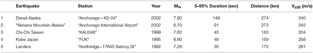
Table 2. Far-field earthquakes.
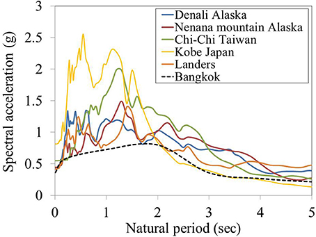
Figure 4. Far-field earthquake response spectra.
Results and Discussions
Non-Linear Static Analysis (Push Over Analysis)
Firstly, push over analysis is used to define the direction of earthquake that can affect highest response of OHLE by applying static force to the structure. The displacements are measured at the end of cantilever which is the location of overhead wire to supply the electric power. In fact, the lowest absolute displacement occurs when the earthquake takes place in transverse direction because this axis has more stiffness to resist deformation than another direction. However, the overhead wire displacement in transverse direction affects overhead line system which has limitation of sway movement. Generally, the contact wire runs in a zig-zag path (also called “stagger”), as shown in Figure 5, above the track to avoid wearing a groove in the pantograph. The allowable displacement is assumed to be a construction tolerances of contact wire. Hence, 50 mm construction tolerance of contact wire is used as the maximum displacement at the end of cantilever mast in transverse direction (RailCorp, 2011b).
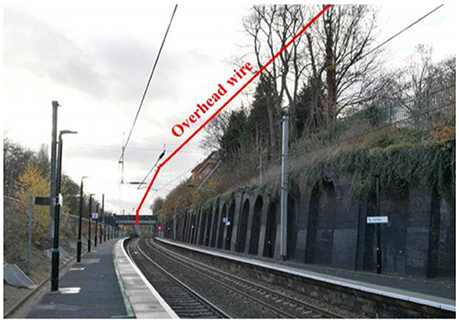
Figure 5. Zig-zag path (stagger) on overhead contact wire.
Even though earthquake occurred in transverse direction should create highest displacement in this direction, this axis has the highest stiffness. Due to the sensitivity of this structure, longitudinal force can also create displacement in transverse if there is an occurrence of coupling mode. Figure 6 shows the maximum displacement occurred at the end of cantilever at various angle of force from 0 to 90 measured from longitudinal direction. However, the maximum transverse displacement occurs when the force is inputted in transverse direction as expected. Therefore, the earthquake are applied in transverse direction.
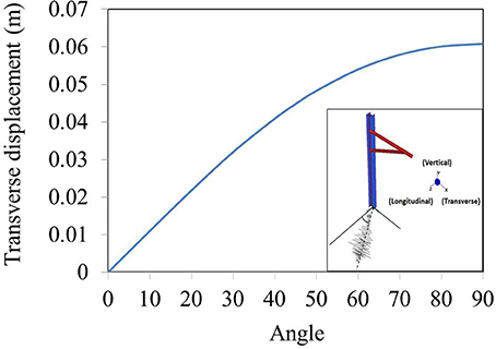
Figure 6. Transverse displacement at various angles caused by static force applied to structure.
Time History Responses
The maximum displacement responses at the end of cantilever of the mast caused by various far-field earthquakes and its support stiffness are presented. This is derived from the dynamic response spectra from the nonlinear analysis over time domain. In theory, the dynamic response spectra correspond to the Earthquake excitation frequency and structural collapse can occur when internal resonance exists. In this study, the Earthquake spectra based on Chi-Chi and Kobe records are considered. This position is chosen because this is the location of overhead contact wire which supplies the electric power to the train. It should be noted that earthquake is applied in the transverse direction as previously describe. Figures 7, 8 show the displacement of OHLE in transverse directions during Chi-Chi and Kobe earthquakes at various support stiffness.
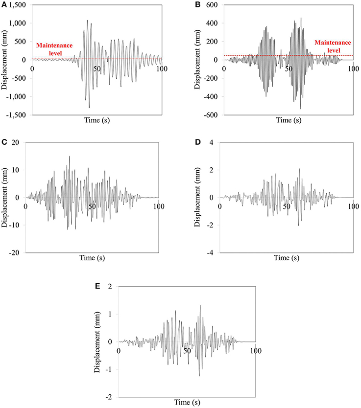
Figure 7. Displacement responses under Chi-Chi earthquake at the position of overhead contact wire on cantilever mast at support stiffness of (A) 100 kNm/rad (B) 1000 kNm/rad (C) 10000 kNm/rad (D) 100000 kNm/rad (E) Fully fixed.
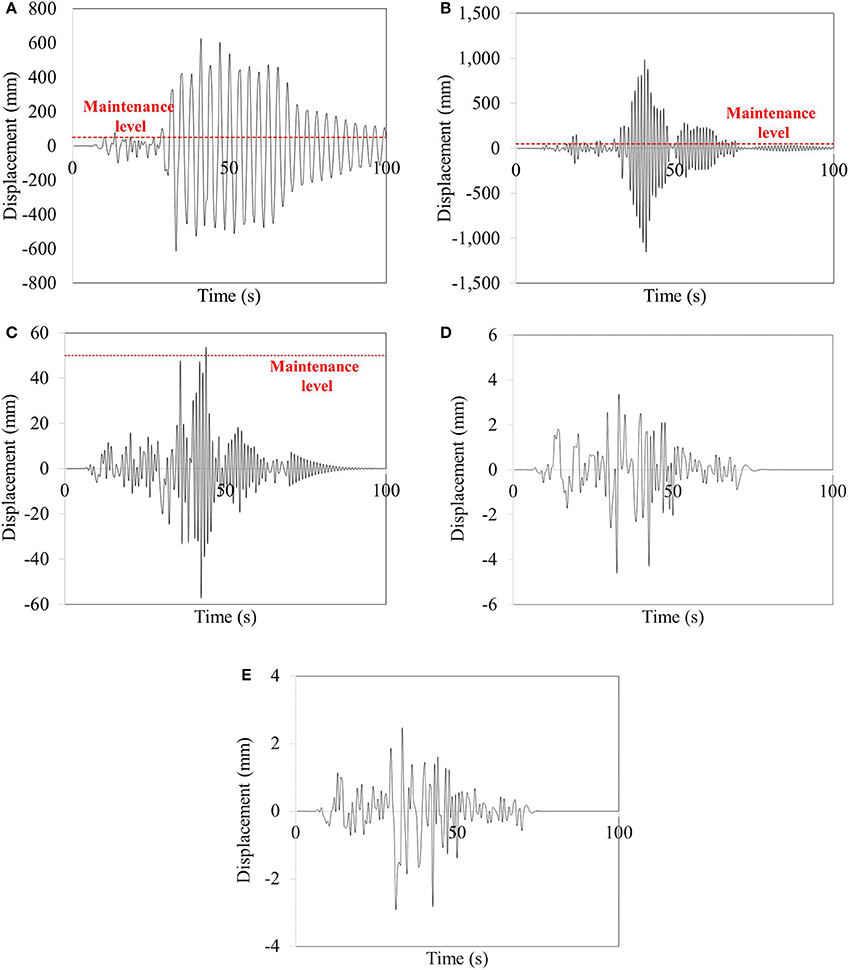
Figure 8. Displacement responses under Kobe Japan earthquake at the position of overhead contact wire on cantilever mast at support stiffness of (A) 100 kNm/rad (B) 1000 kNm/rad (C) 10000 kNm/rad (D) 100000 kNm/rad (E) Fully fixed.
It is observed from Figures 7A, 8A that structure located in the very soft soil condition or bad support (K = 100 kNm/rad) is affected by earthquakes because of the loss of stiffness and contact between soil and structure. It is shown that the failure of contact wire occurs at around 30 and 10 s after Chi-Chi and Kobe earthquakes, respectively (Figures 7A, 8A). However, in case of support stiffness of 1,000 kNm/rad, it is observed that about 15 s after both earthquakes is presented as a failure time of system (Figures 7B, 8B). For the structure with the support stiffness of 10,000 kNm/rad, it can be seen that Chi-Chi earthquake cannot affect the failure of contact wire. Meanwhile, the failure of contact wire on OHLE with its support stiffness of 10,000 kNm/rad is observed during Kobe earthquake, as shown in Figure 8C. However, the responses of OHLE can be reduced and vanish immediately by increasing the stiffness of soil. Therefore, the failure of contact wire can be detected within 50 s after earthquake occurs. The train can decelerate to stop before the failure of the electric system.
Maximum Displacement
Figure 9A shows the maximum displacement occurred at the overhead wire in transverse directions at various support stiffness. The 4-earthquakes have the same trends on structural responses which is the increase of displacement when the stiffness decreases. The amplitudes of OHLE responses are related to the magnitude and dominant frequencies of earthquakes. As for Kobe earthquake, the maximum displacements show the different trend as others. The maximum displacement at the soil stiffness of 1,000 kNm/rad is greater than that of 100 kNm/rad. Due to the change of natural frequency, even the mast structure is more flexible, the frequency of earthquake does not match the fundamental frequency of mast structure as can be seen in Figure 4 so that the displacement responses of OHLE at the support stiffness of 100 kNm/rad show the lowest displacement comparing to earthquakes. Moreover, in case of Kobe earthquake, the response spectra curve shows that the PGA has a slight increase between 0 and 0.8 Hz until it reaches the peak at the frequency of 0.9 Hz which is close to the fundamental frequency of mast structure at the support stiffness of 1,000 kNm/rad. Hence, the resonance can be observed in this condition.
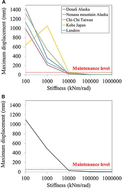
Figure 9. Maximum displacements at the position of overhead contact wire on cantilever mast at various stiffness in transverse direction under (A) earthquakes (B) average displacement.
Overall, it is clearly seen that earthquake can affect the failure of electrical system based on the assumption that the system failure occurs when the transverse displacement of overhead contact wire is greater than 50 mm. Figure 9 shows that about 30 mm average displacement is observed when the cantilever is located in the support stiffness of 10,000 kNm/rad. When the support stiffness decreases to 1,000 and 100 kNm/rad, about 480 and 1,100 mm, respectively, average displacement are observed which are much larger than maximum value. Hence, In this case, no trains can run until the broken wire is fixed. In fact, the design stiffness of soil beneath the structure must have the value more than this value. However, the soil stiffness might be reduced due to the strength degradation or environmental events such as erosion, seepage etc. which lead to the loss of soil stiffness. Moreover, the steel to foundation connection is also a reason of support stiffness reduction due to the connection failures such as broken bold, yielding weld, improper design and construction etc.
Beating Phenomenon
Even though the direction concerned for overhead contact wire monitoring is transverse direction, the beating phenomenon, which normally observed in tall building, is clearly detected in cantilever mast structure when earthquake is applied in longitudinal direction. The beating phenomenon is a periodic vibration caused by distinctive coupling between translational and torsional modes which have close natural frequencies (Çelebi, 1994, 2007; Suhairy, 2000; Mayoof, 2009; Çelebi et al., 2016). This phenomenon has a significant effect on the elongation of structure shaking especially lightly damped structure. It is noted that the stiffness of soil and natural frequency have a direct variation with damping coefficient.
The beating phenomenon can be clearly seen from the response in term of frequency domain. The fast fourier transform (FFT) is used to transform the response from time domain to frequency domain. The two peaks can be obviously observed. The beating period can be computed by the following equation (Boroschek and Mahin, 1991):
Where fb is the beating frequency, difference between two peak frequencies (f1, f2).
Figure 10 shows the displacement responses of OHLE at rigid soil condition under Kobe earthquake in term of time domain and frequency domain, respectively. The two major peaks at around 0.93 and 1.07 Hz are clearly appeared, as shown in Figure 10B. To confirm this phenomenon, beating period and oscillation period should be calculated by the relationship of time and the number of cycles in order to obtain the two peak frequencies. The beating period calculation is shown in Figure 10B while, the oscillation period is computed by beating period divided by the number of cycles in one beating period.
After solving the system of two equations, the two frequencies are f1 = 1.05 s and f2 = 0.89 s. It is noted that the differences between calculation of time domain response and frequency domain response are less than 5%. Therefore, the calculation shows a consistent between the time domain and the frequency domain. It is concluded that the beating phenomenon can occur in the OHLE system during far-field earthquakes.
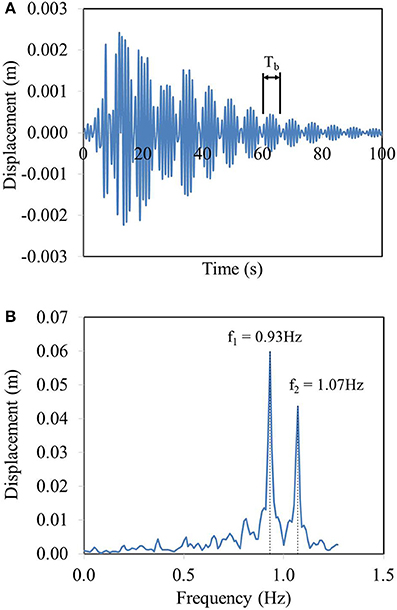
Figure 10. Displacement of OHLE at rigid support in longitudinal direction under unscaled Kobe earthquake in term of (A) time domain (B) frequency domain.
Conclusions
The overhead line equipment (OHLE) is an important asset of the railway infrastructure and is one of the most vulnerable ones. For one or two railway tracks, the support of OHLE is cantilever mast which is normally made of H-section steel column. Although the concept of OHLE is simple, the problem is poor dynamic behavior of OHLE are needed to develop. The dynamic behavior of cantilever mast has not been fully investigated. The three-dimensional cantilever mast structure is created using finite element package STRAND7 with the consideration of soil-structure interaction. The five far-field earthquakes with the magnitude of 6.5–8 Mw are considered in this study. This paper indicates the effects of far-field earthquake excitations on cantilever mast structure located alongside the railway track. The support stiffness underneath the structure is considered. The position concerned is the end of the cantilever which is the location of overhead contact wire. The finding shows that beating phenomenon can be observed not only in tall or mid-rise building but also in small structure such as cantilever mast. This phenomenon is observed when the earthquake is inputted in longitudinal direction or oblique angles. Beating phenomenon is a dynamic behavior caused by the distinctive coupling of translational mode and torsional mode. This makes an elongation shaking of cantilever mast structure during earthquake excitations. Nevertheless, the direction considered is transverse because the movement of contact wire in this direction can cause the broken wire which lead to the failure of electrical system. The responses indicate that the maximum displacement increases when the support stiffness decreases. Moreover, in case of Kobe earthquake, the responses occurred show that the maximum displacement of OHLE at the soil stiffness of 1,000 kNm/rad is greater than that at the soil stiffness of 100 kNm/rad which is different from other earthquake responses. This is because the change of natural frequency of cantilever mast due to the increase of soil stiffness from 100 to 1,000 kNm/rad seems to have the frequency close to a dominant frequency of Kobe earthquake which leads to the appearance of resonance phenomenon. The results clearly show that the responses of the cantilever mast are depended on the frequencies of earthquake excitations which can be seen in the response spectral curve. Surprisingly, the displacements observed at the contact wire are greater than the allowable value when the support stiffness is less than around 9,000 kNm/rad. The reasons of the losses of support stiffness are the connection failure, such as broken bold, yielding weld, and soil erosion and degradation. Therefore, the connection at support should be carefully designed and constructed. The insight shows that condition monitoring of OHLE can be used for earthquake detection so the train could be stopped even faster before the failure of system. This is the world first to investigate the effect of far-field earthquake on overhead line equipment. The outcome of this study will help a better understanding of the critical responses and dynamic behavior of cantilever mast structure and its support under earthquake in order to improve the design standard of this structure.
Author Contributions
CN and SK developed the concept and model. CN performed the seismic analysis and model verification. SK and CB reviewed the results. CN, SK, and CB wrote the manuscript.
Funding
The authors are sincerely grateful to European Commission for the financial sponsorship of the H2020-MSCA-RISE Project No. 691135 RISEN: Rail Infrastructure Systems Engineering Network, which enables a global research network that tackles the grand challenge in railway infrastructure resilience (Kaewunruen et al., 2016) and advanced sensing in extreme environments (www.risen2rail.eu).
Conflict of Interest Statement
The authors declare that the research was conducted in the absence of any commercial or financial relationships that could be construed as a potential conflict of interest.
Acknowledgments
The first author gratefully appreciates the School of Engineering and Birmingham Centre for Railway Research and Education for his PhD scholarship. The authors wish to gratefully acknowledge the Pacific Earthquake Engineering Research Center (PEER) for the ground motion database. The authors appreciate the support from Edward Drayton (Morgan Sindall Rail Group) for field data.
References
Beagles, A., Fletcher, D., Peffers, M., Mak, P., and Lowe, C. (2016). Validation of a new model for railway overhead line dynamics. Proc. Inst. Civil Eng. 169, 339–349. doi: 10.1680/jtran.16.00020
Benedettini, F., Zulli, D., and Alaggio, R. (2009). “Frequency-veering and mode hybridization in arch bridges,” in Proceedings of the IMAC-XXVII (Orlando, FL).
Boroschek, R. L., and Mahin, S. A. (1991). Investigation of the Seismic Response of a Lightly-Damped Torsionally-Coupled Building. Earthquake Engineering Research Center Report, University of California, Berkeley, CA. UCB/EERC-91/18, 291.
Çelebi, M. (1994). “Response study of a flexible building using three earthquake records,” in Proc. Structures Congress XII (Atlanta, GA), 1220–1225.
Çelebi, M. (2007). “Beating effect identified from seismic responses of instrumented buildings,” in Proceedings of the American Society of Civil Engineers Structures Congress: New Horizons and Better Practices (Long Beach, CA).
Çelebi, M. S., Farid Ghahari, S. F., and Taciroglu, E. (2016). “Significance of beating observed in earthquake responses of buildings,” in Conference: 16th U.S.-Japan-N.Z. Workshop on the Improvement of Structural Engineering and Resiliency (Nara).
Davoodi, M., and Sadjadi, M. (2015). Assessment of near-field and far-field strong ground motion effects on soil-structure SDOF system. IJCE 13, 153–166. doi: 10.22068/IJCE.13.3.153
G+D Computing (2001). Using Strand7: Introduction to the Strand7 Finite Element Analysis System. Sydney, NSW.
Jonsson, J. O. (2000). On Ground and Structural Vibrations Related to Railway Traffic. Chalmers University of Technology, Göteborg.
Kaewunruen, S., Sussman, J. M., and Matsumoto, A. (2016). Grand challenges in transportation and transit systems. Front. Built Environ. 2:4. doi: 10.3389/fbuil.2016.00004
Kouroussis, G., Connolly, D. P., Alexandrou, G., and Vogiatzis, K. (2015). Railway ground vibrations induced by wheel and rail singular defects. Vehicle Syst. Dyn. 53, 1500–1519. doi: 10.1080/00423114.2015.1062116
Kouroussis, G., Connolly, D. P., and Verlinden, O. (2014). Railway-induced ground vibrations – a review of vehicle effects. Int. J. Rail Transport. 2, 69–110. doi: 10.1080/23248378.2014.897791
Kouroussis, G., Van Parys, L., Conti, C., and Verlinden, O. (2013). Prediction of ground vibrations induced by urban railway traffic: an analysis of the coupling assumptions between vehicle, track, soil, and buildings. Int. J. Acoust. Vibr. 18, 163–172. doi: 10.20855/ijav.2013.18.4330
Kurzeil, L. G. (1979). Ground borne noise and vibration from underground rail systems. J. Sound Vibr. 66, 363–371. doi: 10.1016/0022-460X(79)90853-8
Madshus, C., Bessason, B., and Harvik, L. (1996). Prediction model for low frequency vibration from high speed railways on soft ground. J. Sound Vibr. 193, 195–203. doi: 10.10006/jsvi.1996.0259
Mayoof, F. N. (2009). Beating phenomenon of multi-harmonics defect frequencies in a rolling element bearing: case study from water pumping station. World Acad. Sci. Eng. Technol. 57, 1062–1066. Available online at: https://pdfs.semanticscholar.org/d517/038940725dcb49902c9ade938e7a26c35531.pdf?_ga=2.78150294.385298055.1530368252-620874007.1530368252
NEHRP Consultants Joint Venture (2012). Soil-Structure Interaction for Building Structures. National Institute of Standards and Technology.
Ngamkhanong, C., Kaewunruen, S., Baniotopoulos, C., and Papaelias, M. (2017). “Crossing phenomena in Overhead Line Equipment (OHLE) structure in 3D space considering soil-structure interaction,” in IOP Conf. Series: Materials Science and Engineering (Bristol, UK), 245.
Ngamkhanong, C., and Pinkaew, T. (2015). “Effectiveness of tuned mass damper in damage reduction of building under far-field ground motions,” in 5th ECCOMAS Thematic Conference on Computational Methods in Structural Dynamics and Earthquake Engineering (Crete), 972–983.
Pierre, C. (1988). Mode localization and eigenvalue loci veering phenomena in disodered structures. J. Sound. Vibr. 126, 485–502. doi: 10.1016/0022-460X(88)90226-X
Prum, S., and Jiravacharadet, M. (2012). “Effects of soil structure interaction on seismic response of buildings,” in International Conference on Advances in Civil Engineering for Sustainable Development (Nakhon Ratchasima).
RailCorp (2011a). Design of Overhead Wiring Structures & Signal Gantries. Engineering Manual –Civil.
Robinson, P., and Bryan, C. (2009). Network Rail Electrical Power Reliability Study. Milton Keynes: Network Rail
Sari, M., Shaat, M., and Abdelkef, A. (2017). Frequency and mode veering phenomena of axially functionally graded non-uniform beams with nonlocal residuals. Compos. Struct. 163, 280–292. doi: 10.1016/j.compstruct.2016.11.093
Shing, A. W. C., and Wong, P. P. L. (2008). “Wear of pantograph collector strips. J. Rail Rapid Transit. 222, 169–176. doi: 10.1243/09544097JRRT156
Keywords: far-field earthquake, overhead line equipment, cantilever mast, overhead contact wire, soil-structure interaction, resonance phenomenon, beating phenomenon
Citation: Ngamkhanong C, Kaewunruen S and Baniotopoulos C (2018) Far-Field Earthquake Responses of Overhead Line Equipment (OHLE) Structure Considering Soil-Structure Interaction. Front. Built Environ. 4:35. doi: 10.3389/fbuil.2018.00035
Received: 01 December 2017; Accepted: 21 June 2018;
Published: 10 July 2018.
Edited by:
Sanjay Shrawan Nimbalkar, University of Technology Sydney, AustraliaReviewed by:
Anindya Pain, Central Building Research Institute (CSIR), IndiaYifei Sun, Hohai University, China
Copyright © 2018 Ngamkhanong, Kaewunruen and Baniotopoulos. This is an open-access article distributed under the terms of the Creative Commons Attribution License (CC BY). The use, distribution or reproduction in other forums is permitted, provided the original author(s) and the copyright owner(s) are credited and that the original publication in this journal is cited, in accordance with accepted academic practice. No use, distribution or reproduction is permitted which does not comply with these terms.
*Correspondence: Sakdirat Kaewunruen, s.kaewunruen@bham.ac.uk; sakdirat@gmail.com