Analog Models of Fold-and-Thrust Wedges in Progressive Arcs: A Comparison With the Gibraltar Arc External Wedge
 Alejandro Jiménez-Bonilla1*
  Ana Crespo-Blanc1 Juan C. Balanyá2
  Inmaculada Expósito2 Manuel Díaz-Azpiroz2
- 1Departamento de Geodinámica-Instituto Andaluz Ciencias de la Tierra, Universidad de Granada-CSIC, Granada, Spain
- 2Departamento de Sistemas Físicos, Químicos y Naturales, Universidad Pablo de Olavide, Seville, Spain
The timing and kinematics of the different types of structures and the associated vertical-axis rotations that permit an arcuate external wedge to acquire progressively its curved shape throughout its deformation history—known as progressive arcs—are key questions in natural cases of arcuate fold-and-thrust belts that we want to address through analog modeling. We present laboratory models of fold-and-thrust belts formed with a backstop that deforms in map view to simulate progressive arcs in a thin-skinned tectonic regime. Our setup makes use of a deformable backstop rigid enough to push from behind the initial parallelepiped but deformable in map view. This innovative design permits us to increase the amplitude of the arc indenting in the model as its radius of curvature decreases, that is, it simulates a progressive arc. Taking the Gibraltar Arc external wedge situated in the western Mediterranean to scale our models in terms of rheology, velocities, and sizes, four types of experiments were made. We varied the type of substratum (sand or silicone), the silicone thickness, and the width and length of the initial analog pack in order to test the influence of each of these parameters on the resulting fold-and-thrust belts. All experiments led to the formation of arcuate wedges where strain was partitioned into: (a) arc-perpendicular shortening, accommodated by thrusts which main structural trend is broadly subparallel to the indenter shape and with divergent transport directions, and (b) arc-parallel stretching, accommodated by normal and conjugate strike-slip faults. The normal and strike-slip faults contributed to the fold-and-thrust belt segmentation and the formation of independent blocks that rotated clockwise and counterclockwise depending on their position within the progressive arc. Our experiments allow to simulate and understand the finite deformation mode of the external wedge of the Gibraltar Arc. Accordingly, they shed light on how an arcuate fold-and-thrust belt can develop progressively in terms of structural trend and transport directions, types and distribution of the structures accommodating strain partition, and timing of vertical-axis rotations.
Introduction
The fold-and-thrust belts of orogenic systems that exhibit map-scale curves are puzzling structures that frequently generate debate. Among others, key questions are the type of structures that permit an arcuate fold-and-thrust belt to acquire progressively its curved shape and the relationships of these structures—in terms of timing and kinematics—with the vertical-axis rotations in the different parts of the arcuate belt (e.g., Marshak, 2004; Weil and Sussman, 2004). Regarding this question, while primary arcs are characterized by uniform displacement directions and do not involve significant late stage vertical-axis rotations, secondary arcs (or oroclines) are formed by pure bending of an initially straight fold-and-thrust belt (Eldredge et al., 1985; Hindle and Burkhard, 1999; Weil et al., 2010). Nevertheless, primary and secondary arcs are only two end-members of an oversimplified classification. In fact, most arcuate external fold-and-thrust belts of orogenic systems acquired their curvature progressively throughout their deformation history. These are known as progressive arcs, in which differential vertical-axis rotations along the arc limbs occur during folding and thrusting (Weil and Sussman, 2004; Musgrave, 2015).
The best way to quantify vertical-axis rotation in arcuate fold-and-thrust belts goes hand in hand with paleomagnetic analysis (e.g., Schwartz and Van der Voo, 1983; Weil et al., 2012; Johnston et al., 2013; and references therein), but a full understanding of arc kinematic evolution must be complemented with other approaches. Among a wide range of methods, analog modeling is a powerful tool that permits not only to compare the finite deformation in both natural cases and models but also to investigate the strain field associated with variations of the indenter geometry.
Such methodology permits to test the influence of some of the parameters that control the development of arcuate structural patterns in external zones. Some of these parameters are: (a) the variations in thickness of the deforming layers (e.g., Marshak and Wilkerson, 1992; Calassou et al., 1993; Mitra, 1997; Corrado et al., 1998; Soto et al., 2002; Storti et al., 2007); (b) the lateral variations in the rheology of the detachment and/or that of the deforming layers (Mitra, 1997; Macedo and Marshak, 1999; Cotton and Koyi, 2000; Schreurs et al., 2001; Bahroudi and Koyi, 2003; Luján et al., 2003, 2006b; Reiter et al., 2011); (c) the topography of the foreland (Marques and Cobbold, 2002); (d) the syn-tectonic sedimentation and/or erosion (Wu et al., 2015); (e) the presence of obstacles of different shapes and strength and/or previous structures (Marshak et al., 1992; Dominguez et al., 2000; Duarte et al., 2011; Ter Borgh et al., 2011); and (f) the shape, velocity, and motion direction of the indenter (Lu and Malavieille, 1994; Zweigel, 1998; Macedo and Marshak, 1999; Lickorish et al., 2002; Marshak, 2004; Crespo-Blanc and González-Sánchez, 2005; Crespo-Blanc, 2007, 2008; Reiter et al., 2011; Crespo-Blanc et al., 2012, 2018; Rauch, 2013).
In all these models, the indenter used to generate thin-skinned, curved fold-and-thrust belts was rigid and maintained shape and size during the whole experiment. These rigid indenter models failed to reproduce some conspicuous features observed in many arcuate fold-and-thrust belts, such as widespread arc-parallel stretching, thicker wedges in the lateral branches, or strong vertical rotations, as observed, for example, in the western Mediterranean arcs (Figure 1A; e.g., Balanyá et al., 2007 and Crespo-Blanc et al., 2016 for the Gibraltar Arc and Cifelli et al., 2016 for the Calabrian Arc). So, we modified the experimental setup by using a backstop that can progressively deform during the experiment as observed in western Mediterranean arcs.
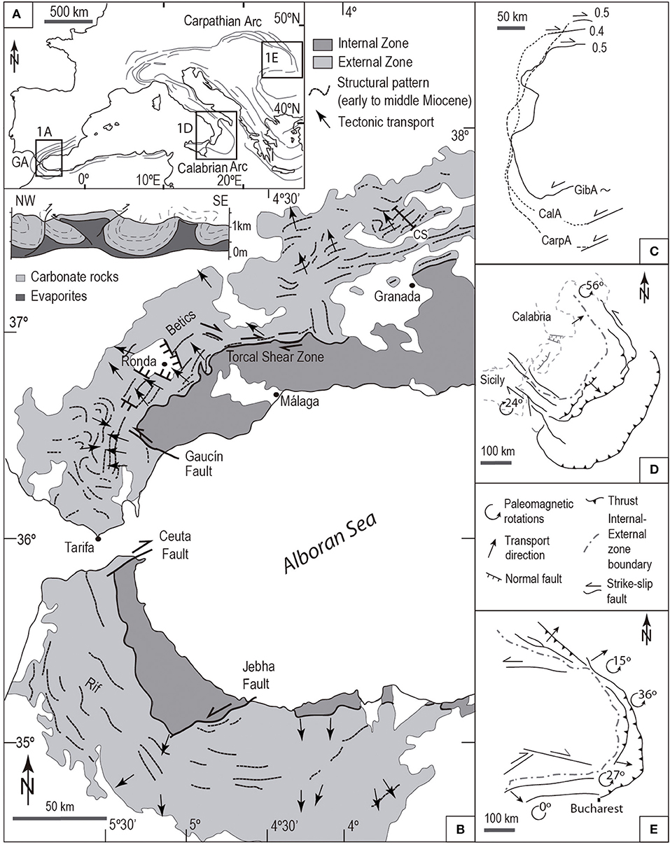
Figure 1. (A) Map of the Mediterranean region with a sketch of the structural trend lines of the orogenic arcs. (B) Simplified structural map of the Gibraltar Arc with structural trend and kinematic vectors (Crespo-Blanc et al., 2016). Representative cross section (cs) of the external wedge (Crespo-Blanc, 2007). (C) Comparison of the geometry and degree of protrusion of the Carpathian (CarpA), Calabrian (CalA), and Gibraltar (GibA) arcs (reference line: internal–external zone boundary according to Linzer, 1996; Crespo-Blanc et al., 2016; Gutscher et al., 2017, respectively). (D,E) Simplified tectonic maps of the Calabrian and Carpathian arcs, respectively, with displacement vectors along thrusts and vertical-axis rotations (see text for references).
As a natural case, we take the Gibraltar Arc external wedge situated in the westernmost Mediterranean (Figure 1A) in order to scale the materials, setup, and convergence velocities of our analog models. We present the results of experiments with a flexible backstop that deformed in map view while the experiment progressed. Meanwhile, the deformable backstop pushed from behind the parallelepiped of analog materials; the backstop geometry varied from straight to arcuate. The arc amplitude and length increased, whereas its curvature ratio diminished. So, these are the first models of progressive arcs, which simulate natural cases of arcuate fold-and-thrust belt migrating toward the foreland pushed from behind by an inner orogenic domain (crystalline internal zones) in orogenic arc systems associated with back-arc extension (area increase).
We will focus on several major questions concerning: (a) how this thin-skinned, arcuate fold-and-thrust belt progressively acquires its curvature, (b) what factors control its shape and internal geometry (in particular, the role of strain partitioning), (c) whether or not deformational structures passively—or actively—rotate during arc evolution, and (d) how the geometrical relationships between structures and displacement vectors evolve with increasing deformation. In our models, the strain partitioning modes generate highly arcuate wedges, segmented in blocks that rotated differentially. We will compare our results with those features observed in the Gibraltar Arc natural case in terms of deformation sequence, geometry of the progressive arc external wedge, and timing of vertical-axis rotations.
The Gibraltar ARC External Wedge, a Natural Case of Progressive ARC Fold-and-Thrust Belt
Bearing in mind that our purpose is to model an arcuate fold-and-thrust belt formed in front of a flexible indenter that simulates the backstop of a progressive arc, several constraints extracted from a natural case must be imposed on our laboratory model setups. We selected the external zones of the Gibraltar Arc System, the alpine orogenic system formed by the Betic-Rif mountain chains, which close the western Mediterranean (Figure 1B). Indeed, its mode of deformation, strain partitioning, kinematics, timing, and vertical axis-rotations are reasonably well-known, particularly in its northern branch (see review in Crespo-Blanc et al., 2016, 2018).
Within this orogenic system, we will zoom on the arcuate fold-and-thrust belt located in the Western Gibraltar Arc (WGA). This arc is defined as the westernmost salient of the Gibraltar Arc System (west of 4°30′). Its transition zones to the adjacent recesses are two strike-slip dominated shear zones (Figure 1B): the Torcal shear zone in the Betics and the Jebha fault zone in the Rif (Balanyá et al., 2007, 2012; Barcos et al., 2015).
The key data to constrain our analog model setup are the following: (1) the chord line length of the WGA measured at the external–internal zone boundary is around 185 km for an amplitude of 90 km; accordingly, the WGA degree of protrusion, that is, the ratio between arc amplitude and chord line (Macedo and Marshak, 1999) reaches 0.5; (2) the external fold-and-thrust-belts were pushed from behind by the internal zones, while the internal–external zone boundary underwent a significant length increase simultaneous with an area increase of the internal zones due to back-arc extension (Comas et al., 1999; Balanyá et al., 2012; Crespo-Blanc et al., 2018); (3) deformation velocities in the external wedge measured around the arc apex in the WGA northern branch vary between 0.9 and 1.5 cm/year (geometry of Luján et al., 2006a combined with timing data of Crespo-Blanc et al., 2016); (4) the WGA external fold-and-thrust belt is mainly formed by palaeomargin derived, Mesozoic–Cenozoic sedimentary covers; (5) in the Betics (WGA northern branch), 1,300–2,000 m of carbonate sequence overlays 100–1,000 m of Triassic evaporites (Vera, 2004; Jiménez-Bonilla et al., 2016), whereas in the Rif (WGA southern branch), a minimum of 4,000 m of clastic sediments are present (Chalouan et al., 2008); (6) the structural style of the external wedge in the northern branch of the Gibraltar Arc corresponds to a fold-and-thrust belt developed on an evaporitic, viscous substrate (see representative cross-section in Figure 1B), with pop-up and pop-down structures separated by large synclines (Crespo-Blanc and Campos, 2001; Expósito et al., 2012; Crespo-Blanc et al., 2016).
Experimental Setup
Material Properties
The experiments were performed in the Analog Modeling Laboratory of the Geodynamics Department-IACT of the University of Granada-CSIC (Spain). Sand and silicone were used as analog materials in a natural gravity field to simulate the brittle, rate-independent behavior of most sedimentary rocks and the ductile, rate-dependent flow of evaporitic rocks, respectively (Schellart and Strak, 2016; and references therein). The quartz sand was dry and rounded, with a grain size varying between 0.2 and 0.3 mm, a coefficient of internal friction of 37°, and a density δbM = 1.77 g/cm3 (Table 1). Colored sand provided horizontal passive markers within the undeformed experimental multilayer. The silicone putty used in our experiments (transparent Rhodosil Gum FB of Rhone-Poulenc) is a Newtonian material at experimental strain rates (10−6 s−1), with a density δdM = 0.98 g/cm3 and a viscosity ηM = 5 × 10⁴ Pa s at room temperature (Table 1; Funiciello et al., 2003). The initial analog silicone and sand parallelepiped (from now on, sandpack) was underlain by a Mylar sheet (coefficient of basal friction 0.43), and its boundaries were confined by sand, with the exception of the one limited by the indenter.
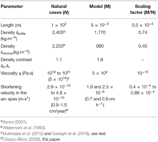
Table 1. Scaling parameters between natural cases and models.
Model Setup
The sandbox is schematically illustrated in Figure 2A, and the terms used in this paper to describe the parts of the experimental arc are shown in Figure 2B. The innovation of our models comes from the fact that the curvature of the backstop employed to deform the sandpack progressively increased. We used a plastic strip pushed from behind in its apex by a screw attached to a motor drive. We obliged this strip to go through a 62 cm wide gate, which represents the chord line of our experimental arcs. The chord line remained constant, while the amplitude and perimeter of the arc increased progressively as the limbs rotated (observe the progressive shape change of the strip in Figure 2C, from S0 to S3). Consequently, the protrusion degree of the indenter progressively increased. It must be stressed that the strip was sufficiently rigid to keep a convex shape and push the sandpack.
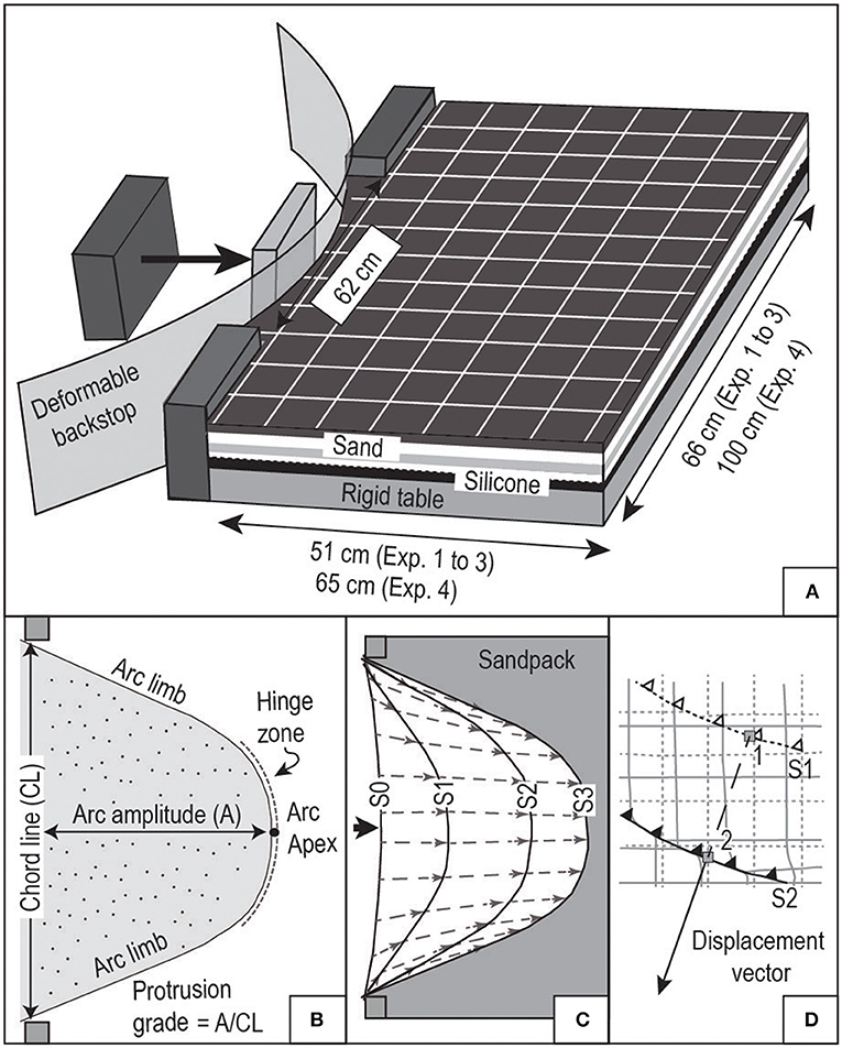
Figure 2. (A) Simplified sketch of the experimental apparatus and model setup. (B) Sketch showing the terminology used in the paper. (C) Shape and particle displacement paths of the deformable indenter for different deformation stages (S1 to S3). (D) Sketch of the measurement of a displacement vector (arrow) between two successive deformation stages (S1 and S2).
At the beginning of each experiment, the increase of the protrusion grade took place hand in hand with the decrease of the backstop curvature ratio (S1 in Figure 2C). When the apex displacement reached ca. 20 cm, the plastic strip attained its maximum possible curvature. From that moment, the backstop moved toward the front similar to a rigid indenter (the protrusion grade increased, but the curvature ratio at the apex remained constant). During the whole experiment, the path of selected points along the indenter displayed a slightly convergent pattern, particularly in the arc limbs (Figure 2C).
The indenter apex moved at a constant velocity (0.7 or 0.9 cm/h, Table 2). The maximum amplitude reached by the indenter varies between 20 cm and 40 cm, which corresponds to indenter degrees of protrusion between 0.32 and 0.65, respectively.
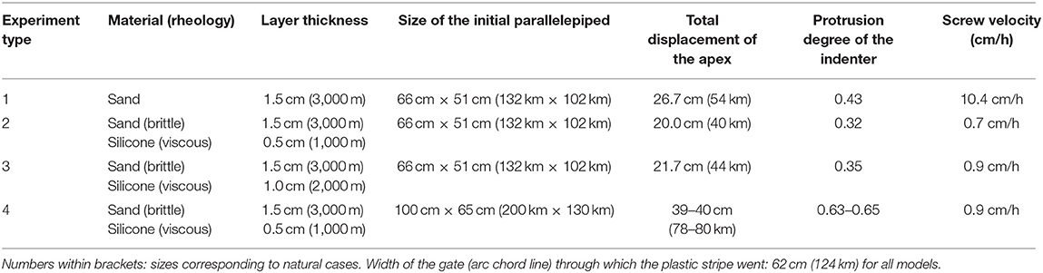
Table 2. Model settings.
A reference 3 × 3 cm grid was sieved on top of the sandpack. The progressive deformation was monitored by time lapse photography of the model surface every 10 min, and its final geometry was recorded by oblique photographs. Representative cross sections of the deformed models were also made. At the end of some of the experiments, the sand was carefully removed to observe the final 3D geometry of the silicone.
Scaling
The characteristic values of density (δ), length (l), viscosity (η), and velocity (v) for both the natural case (subscript N) and the analog model materials (subscript M), together with the relative scaling factors of these main physical parameters, are summarized in Table 1 for natural gravity conditions (gN = gM = 9.81 m/s2). It can be observed that the density contrast between sedimentary rocks and evaporites in the natural case is lower than that between sand and silicone in the models (1.1 vs. 1.8). That means that the buoyancy of the ductile layer in the model is larger than that in the natural cases. This limitation is common in sand–silicone analog experiments, and it has been shown that it does not affect first-order model results (e.g., Bonini, 2001; Bahroudi and Koyi, 2003; Ferrer et al., 2016; Roma et al., 2018). For the viscous layer, we used the Hormuz evaporites as reference, with a viscosity range from 1018 to 1021 Pa s (Mukherjee et al., 2010; Sadeghi et al., 2016; Table 1). Indeed, the structure of the Zagros fold-and-thrust belt is similar to that observed in the external zones of the Gibraltar Arc northern branch (e.g., Sherkati et al., 2005).
We set a length ratio (lM/lN) of 0.5 × 10⁻⁵ (1 cm in the experiments represents 2,000 m in nature), and with the values of Table 2, we estimated the shortening velocity of the models according to Weijermars and Schmeling (1986):
The variability of the different parameters, in particular the viscosity range of the natural case, introduces a significant uncertainty in the calculation of the shortening velocity of the models, which varies from 0.6 × 10⁻⁶ to 1.7 × 10⁻³ m s−1, that is, 0.2 to 612 cm h−1. However, as we had to ensure that the silicone employed in our analog models behaves as a Newtonian material, we restricted the shortening velocity to 0.7–0.9 cm h−1 (Luján et al., 2006b; Borderie et al., 2018). With these values of shortening velocity, we calculated the strain rate of our analog models as ε = vM/w, where w is the width of the deformable zone measured in the apex parallel to the shortening direction (between 51 and 65 cm). The calculated strain rates vary between 3.7 × 10⁻⁶ s−1 and 4.9 × 10⁻⁶ s−1. Moreover, these velocities of 0.7–0.9 cm h−1 in the models correspond to viscosities in the natural ductile layers of around 5 × 10¹⁹ Pa s (viscosity value inside the brackets in Table 1).
Tested Parameters: Size and Thicknesses
We tested the influence of the rheological stratification by varying the thickness of the ductile layer at the bottom of the undeformed analog pack. After a first round of experiments, we also increased the size of the models with the double purpose of reducing the border effects observed in the first experiments as well as reaching a higher bulk shortening in front of the indenter hinge zone. Accordingly, we made four types of models (Table 2): (1) a 66 cm × 51 cm initial analog pack built only with a brittle layer composed of sand (1.5 cm thick); (2 and 3) a 66 cm × 51 cm initial analog pack floored by a ductile layer of silicone, 0.5 cm and 1 cm thick, respectively, overlain by a 1.5 cm thick sand layer; and (4) a 100 cm × 65 cm initial analog pack floored by a 0.5 cm thick silicone layer overlain by a 1.5 cm thick sand layer. The dimensions to which these values correspond in a natural case using a scale factor of 0.5 × 10⁻⁵ figure into brackets in Table 2. For all experiments, we used the same gate of 62 cm (chord line, equivalent to 124 km in a natural case).
Measurement of Displacement Vectors
For all models, displacement vectors along selected thrusts have been depicted for successive deformation stages. They are drawn by joining reference points of the selected thrust hanging wall in successive deformation stages. For example, the displacement vector along the thrust sketched in Figure 2D corresponds to the mean direction and total displacement of the hanging-wall movement from S1 stage to S2 stage, using a reference point as near as possible to the thrust. Consequently, the vectors on any selected structure at a determined Sx stage represent the mean direction and total displacement of the hanging-wall movement from that stage and the previous one, that is, from Sx−1 to Sx stage. The corresponding arrows have been drawn with their origin on the selected thrust, or eventually on the normal fault.
Analog Modeling of Progressive ARCS: Results
Small Sandpack Composed Only by Sand: Model 1
When a backstop simulating a progressive arc is indented in a sandpack composed only by sand, a typical piggyback, foreland-verging thrust system is formed (Figure 3A). These thrusts are rooted at the bottom of the sandpack and are associated with accommodation folds. In the line drawing of the final stage of the experiment, the relative chronology of the structures is shown by numbering (Figure 3A). Additionally, the complete deformation sequence can be observed in Supplementary Video 1.
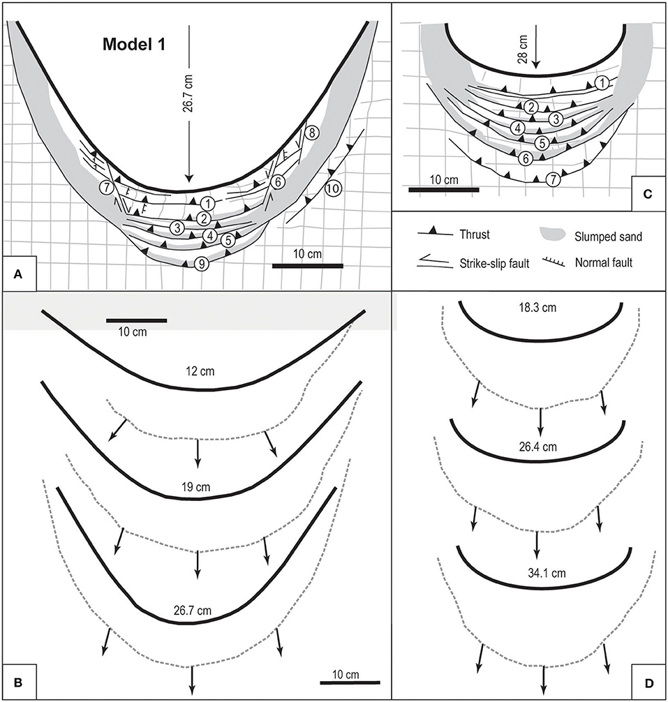
Figure 3. Line drawings of experiments with an initial sandpack: (A) Model 1: final stage. The numbering indicates the chronology of the structures. (B) Model 1: progressive displacement of the frontal thrust (dashed line) for various positions of the indenter (numbers: apex movement) and displacement vectors along this thrust (arrows). (C,D) idem (B,C), respectively, from a model of Crespo-Blanc and González-Sánchez (2005) with a rigid indenter.
The trend-line pattern displays an arcuate geometry, which mimics as a whole the indenter shape, although with a slightly higher degree of protrusion. This is due to the effect of two conjugate strike-slip faults that extrude a salient at the hinge zone of the arcuate wedge, defined by the most external thrust (thrust 9, Figure 3A).
The first thrusts formed subparallel to the backstop boundary (see Supplementary Video 1). Then, the length of the most external arcuate thrust increased together with the width of the area affected by shortening. Nevertheless, when the indenter amplitude reached ~10 cm, the width of the deformed wedge in front of the indenter hinge zone remained relatively constant until the end of the experiment (see Supplementary Video 1).
At the beginning of the experiment, displacement vectors were at 90° to the strike of the new, most external thrust (arrows in Figure 3B), but as shortening proceeded, this angle diminished from the arcuate wedge hinge toward both limbs, from 90° to ~65°, respectively. Accordingly, at the first stage of the experiment, the displacement vectors directions defined a range of around 60° along the arcuate wedge frontal thrust, whereas this range decreased to only 10° at the end. The outward radial transport produced an arc-parallel lengthening of the grid markers, which was accommodated in the sandpack by arrays of millimetric-spaced normal faults. Because of their very small spacing (see photograph of Figure 4A), these normal faults have been grouped in Figure 3A into single fault trace.
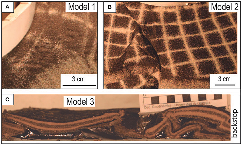
Figure 4. Photographs of various models. (A) Model 1: millimetrical-spaced normal faults (situated to the right of Fault 7 in Figure 3A). (B) Model 2: Conjugated strike-slip faults system and small normal faults (situated to the right of Fault 11 in Figure 5B). (C) Cross section in the arc apex zone of Model 3 (location on Figure 5F).
During the whole experiment, as the indenter curvature increases, the lateral parts of the wedge and the previously formed thrusts rotated around vertical axes. At the end of the experiment, grid markers depict 20–25° clockwise and counterclockwise rotations, left and right of the arc apex, respectively (Figure 3A).
In Figures 3C,D, for comparison purposes (see discussion), we present the results of the analog experiment of Crespo-Blanc and González-Sánchez (2005), which used the same Model 1 rheology (1.5 cm thick sand layer) and an elliptical, rigid backstop. The curvature ratio of that backstop is similar to the minimum reached in our experiments. In the model of Crespo-Blanc and González-Sánchez (2005), displacement vectors along the frontal thrusts are slightly divergent (10° range) and their directions relatively constant during deformation (Figure 3D).
Small Sandpack With Silicone Substratum: Models 2 and 3
Using a constant, 1.5 cm thick upper sand layer, two different experiments were carried out with 0.5 and 1 cm thick lower silicone layers, respectively. The size of the initial sand–silicone pack was 66 × 51 cm (Table 2). The deformation sequence is illustrated by line drawings that compare three different deformational stages with similar indenter amplitude for both models (Figure 5, see also Supplementary Videos 2, 3). In both experiments, the deformation was accommodated by thrusts, backthrusts, and strike-slip faults, all of them rooted within the silicone, as well as thrust-related folds and normal faults. Regardless of their initial kinematics, the regime of some of these faults changed along the experiments. Although the distribution of these structures is different in both types of experiment, the final result was a non-cylindrical, segmented, arcuate fold-and-thrust belt in which apparently undeformed blocks, shown by undistorted grid, rotated differentially. Moreover, buoyant silicone locally reached the model surface.
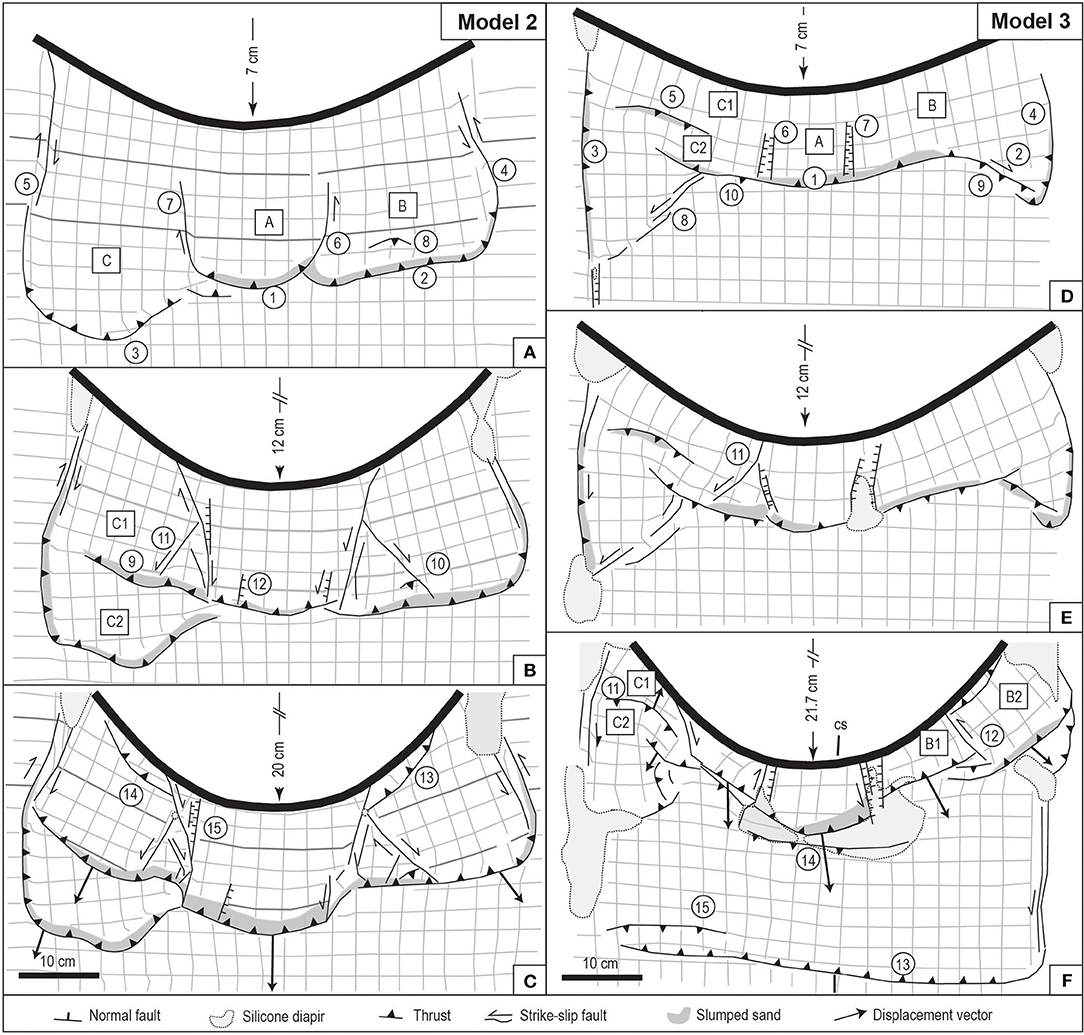
Figure 5. (A–C) Line drawings of different stages of Model 2 (silicone layer of 0.5 cm). (D–F) Line drawings of different stages of Model 3 (silicone layer of 1 cm). The numbering indicates the relative chronology of the structures. The apex displacement is indicated for each stage. Arrows: displacement vectors along some thrusts [drawn between stages (B,C,E,F)]. The length of the arrows represents the magnitude of the displacement with the same scale of the line drawings. Cs, cross section of Figure 4C.
Model 2 (Silicone Thickness: 0.5 cm)
The relative chronology of the structures involved in the deformed wedge is shown by numbering in Figures 5A–C (see also Supplementary Video 2). Shortening was accommodated by a few forethrusts that initiated with a wide spacing and one small subordinate backthrust (number 8). Due to the difference in displacement between thrust sheets, four transfer faults appeared at early stages (faults 4–7 of Figure 5A). They acted as dextral or sinistral faults, in accordance with their position with respect to the arc limbs. The transfer faults facilitated the formation of three blocks (ca. 20 cm wide) that rotated while deformation proceeded. The central block A underwent little vertical axis rotation, whereas blocks B and C significantly rotated counterclockwise and clockwise, respectively. These vertical-axis block rotations were accompanied by arc-parallel lengthening of the wedge front. Such lengthening was accommodated by small normal faults that developed in the hinge zone, subperpendicular to the structural trend of the arcuate wedge. Strike-slip faults developed oblique to the wedge trend (faults 10 and 11 of Figures 5B, 4B). They acted as conjugate faults to the early transfer faults and show a slight normal component of displacement that also contributed to this lengthening. These structures produced small recesses of the wedge front, in the sense of Macedo and Marshak (1999).
As deformation proceeded, a new foreland-verging thrust split block C into two (C1 and C2) and new arc-perpendicular normal faults and strike-slip faults oblique to the wedge trend developed (Figures 5B,C). The rotation of blocks was accommodated not only by these faults but also by the different horizontal heave along the most frontal thrusts. At the final stage, block B rotated 22° counterclockwise and block C1 rotated 26° clockwise (C2 is considered to be influenced by the model border and probably did not rotate freely), whereas the central block A did not rotate significantly (Figure 5C). Thrust displacement vectors between stages B and C were divergent, and their trend varied around 70° (see arrows on Figure 5C).
Model 3 (Silicone Thickness: 1.0 cm)
The relative chronology of the structures is illustrated by the line drawings in Figures 5D–F and Supplementary Video 3. Apart from several similarities with Model 2, the presence of a thicker layer of silicone under the sand layer induced some differences with Model 2: (a) backthrusts occurred more frequently and, together with forethrusts, defined pop-up and pop-down structures (see backthrusts 5, 9, 10, and 14 of Figures 5D–F); (b) two conjugated strike-slip faults formed in the external part of the arcuate deformed wedge (strike-slip faults 2 and 8), and they subsequently evolved into thrusts with a lateral slip component; (c) the size of the individual blocks was smaller, and the amount of vertical-axis rotations increased from the arcuate wedge hinge toward the limbs (blocks B1 and B2 rotated counterclockwise, 33° and 42°, respectively; blocks C1 and C2 clockwise, 34° and 35°, respectively; block A did not rotate; Figure 5F); (d) buoyant silicone walls and canopies were more widespread than in Model 2; and (e) deformation reached the frontal boundary of the initial sand–silicone pack, and the localization of thrust 13 and associated backthrust 15 are considered as border effect.
The total displacement of the wedge front, excluding the faults related to border effect, was similar in both experiments, but Model 3 generated a narrower thrust wedge than Model 2. Shortening in the hinge zone of the arcuate wedge was reached through a rather complex geometry in which two retrovergent folds developed in the footwall of thrust 1 of Figure 5D (see cross section in Figure 4C).
Finally, displacement vectors related to thrusts between stages E and F were divergent and showed a strike range around 60°, similar to those in Model 2.
Large Sandpack With Silicone Substratum: Models 4
In order to reduce the border effects observed in Models 2 and 3, and to reach a higher degree of protrusion, the initial sand–silicone pack was enlarged up to 100 cm × 65 cm (Table 2). The silicone and sand thicknesses were 0.5 cm and 1.5 cm, respectively. In order to check their reproducibility, two experiments were performed with the same initial setting. The final stage of both experiments, with an indenter degree of protrusion of 0.6 and ~40 cm of shortening in front of the arc apex, was similar in terms of type and evolution of the structures. In both cases, the result was a segmented, highly arcuate fold-and-thrust belt, although the distribution of thrusts, backthrusts, strike-slip, and normal faults was slightly different. This is likely due to the unavoidable heterogeneities in the preparation of such large analog models, such as small variation of sand or silicone thicknesses or different packing of the sand grains when the sand layers are made even. We will describe the results pointing out the key aspects of the structures developed in each model. Line drawings of S1 to S4 deformational stages for both experiments are illustrated in Figures 6 (Model 4-1) and 7 (Model 4-2), in which the chronology of structures is indicated by numbering. To facilitate comparison between models, the apex displacement in S2 corresponds to that of the final deformation stage of Models 2 and 3 (~20 cm). The deformation sequence in Models 4-1 and 4-2 can also be seen in the corresponding Supplementary Videos 4, 5, respectively.
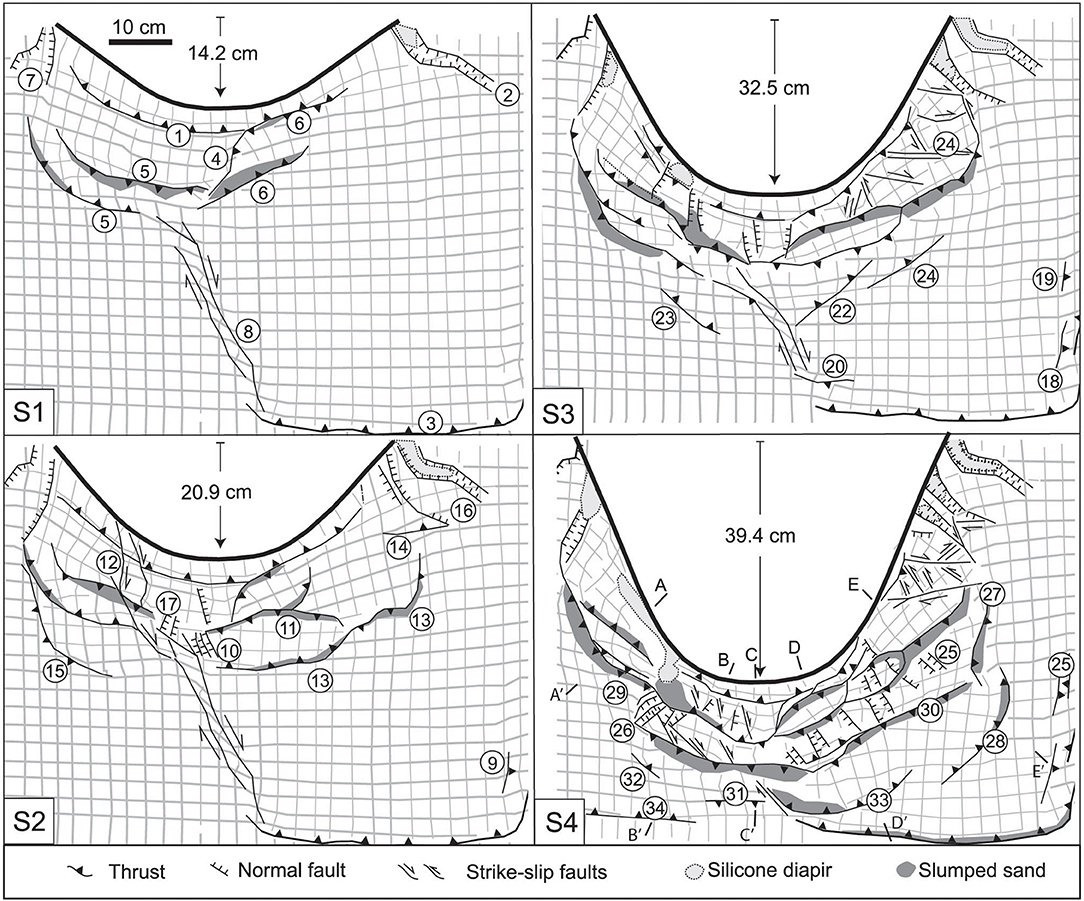
Figure 6. Line drawings of Model 4-1 at different stages (S1–S4). The numbering indicates the relative chronology of the structures. The apex displacement is indicated for each stage. A–E: localization of cross sections of Figure 9.
Photographs of these models are shown in Figure 8 (final stage together with some details of the structures). At the end of the experiment, systematic cross sections were made in Model 4-1. Sand in Model 4-2 was carefully removed to observe the viscous substratum 3D geometry.
Deformation Sequence
At the onset of deformation in both experiments (S1 stage), the radial outward shortening in the sand–silicone pack was accommodated by both forelandward and backward thrusts (thrusts 1, 5, and 6 in Figure 6; thrusts 4 and 8 in Figure 7). In both models, a thrust mimics the frontal boundary of the pack and is considered as a border effect (thrust 3).
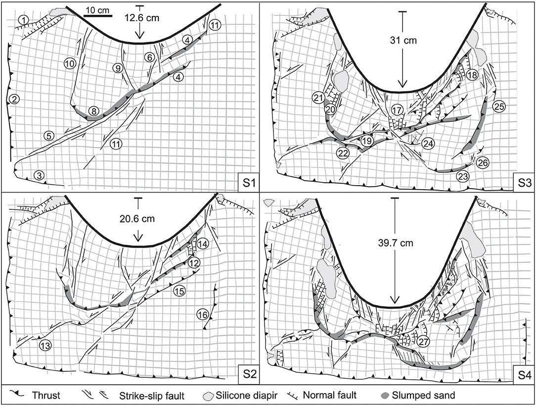
Figure 7. Line drawings Model 4-2 at different stages (S1–S4). The numbering indicates the relative chronology of the structures. The apex displacement is indicated for each stage.
As deformation proceeded, these thrusts were linked by transfer zones with a main component of thrusting (e.g., fault 4 in Figure 6) or strike-slip (fault 6 in Figure 7). At this stage, one or two strike-slip faults appeared, connecting the central part of the fold-and-thrust belt to the frontal boundary of the sand–silicone pack (dextral fault 8 in Figure 6 and sinistral faults 5 and 11 in Figure 7).
As shortening increased (S2 stage, with a backstop apex displacement of ca. 21 cm), the deformation front propagated toward the foreland with the nucleation of curved thrusts and backthrusts (faults 11 and 13 in Figure 6; faults 12 and 15 in Figure 7), generating pop-up and pop-down structures. Meanwhile, ongoing thrusting and tilting of the previous structures thickened the wedge. Differential displacements of the thrusts led to the lengthening of the transfer zones and the vertical-axis rotations of the earlier structures. For example, between stages S1 and S2, faults 5 (Figure 6) and 4 (Figure 7) rotated 5°, clockwise and counterclockwise at the left and right arc limbs, respectively. The kinematics of some faults changed with further deformation, as in the case of fault 5, which evolved from a pure strike-slip fault to a transpressive zone where restraining bends formed (Figure 7). Along-strike lengthening of the arcuate fold-and-thrust belt resulted in arc-parallel extension, mainly accommodated by milli- to centimetric spaced normal faults, mostly oriented subperpendicular to the indenter boundary. These defined conjugated systems form graben structures (Figures 6, 7, 8B,F). Conjugate strike-slip faults also contributed to arc-lengthening (e.g., fault 24 in Figure 6 and fault 6 in Figures 7, 8A,E,G). At this stage, different types of structures delineated discrete blocks that subsequently underwent clockwise or counterclockwise vertical-axis rotations, depending on their location relative to the left or right flank of the arcuate backstop, respectively.
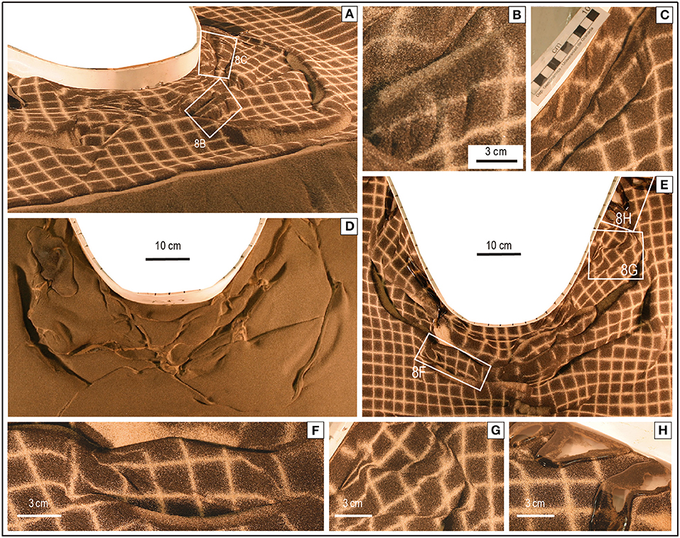
Figure 8. Photographs of Models 4. (A) Oblique photograph of Model 4-2 at its final stage. (B) Millimetrical-spaced normal faults (localized on A). (C) Transpressive bands at the arc limb (localized on A). (D) Silicone topography of Model 4-2 once the sand is removed at the final stage. (E) Zenithal view of Model 4-1 at the completion of the experiment. (F) Millimetrical-spaced normal faults (localized on E). (G) Conjugate strike-slip fault systems (localized on E). (H) Silicone outcropping on the model surface (localized on E).
Between stages S2 and S4, shortening was mostly accommodated either by the previously formed thrusts or by the development of new arcuate thrusts, subparallel to the curved indenter boundary (e.g., faults 28 and 30–33 in Figure 6). At the same time, rotation of early structures proceeded, sometimes associated with variations in their kinematics (e.g., thrusts evolving to transpressive bands; faults 25 and 26 of Figure 7, photographed in Figure 8C). Buoyant silicone pierced the sand layer, preferentially along graben structures (Figures 6, 7, 8A,E,H).
Relay zones between thrust traces correspond to either relay deformation zones where grid markers were rotated ca. 5° (e.g., between 28 and 33 in Figure 6) or strike-slip faults that acted as transfer faults (e.g., fault 26 in Figure 7). Thrusts also formed along the lateral boundary of the confining sand (border effect).
Final Architecture of the Deformed Wedge
The arcuate fold-and-thrust belts generated in Models 4-1 and 4-2 have complex geometries. They show salients and recesses and are sharply segmented along-strike (stage S4 of Figures 6, 7, 8A,E). The deformed wedge is formed by blocks bounded by different types of structures. These blocks underwent clockwise or counterclockwise vertical-axis rotations coherent with their position with respect to the symmetry axis of the indenter. At the completion of the experiments, the grid marker rotations diminished progressively from ca. 60–70° in front of the limbs of the indenter down to 0° in front of its apex.
Arc-parallel lengthening was achieved by conjugate strike-slip and normal faults. Both types of faults played a crucial role on the along-strike segmentation of the fold-and-thrust belt (Figures 6–8). The normal faults did not produce any observable deformation in the silicone layer (Figure 8D) and are consequently detached at the top of the silicone layer or within the sand layer.
A series of cross sections from Model 4-1 are illustrated in Figure 9. The deformed wedge is characterized by foreland and hinterland-verging thrusts and folds (ca. 7 cm-spaced) rooted within the silicone layer, which generate pop-up and pop-down structures. The shortening is maximum in the central part of the model, where a backthrust overlies not only the pop-down structure itself but also the following pop-up structure (rear part of cross section D).
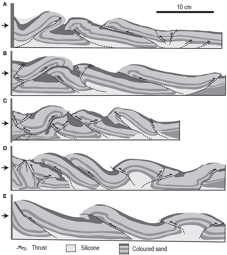
Figure 9. Series of cross sections (A–E) of Model 4-1 (location on Figure 6).
Displacement Vectors Along Selected Structures
Displacement vectors associated with the main structures at different stages of Models 4-1 and 4-2 are shown in Figures 10A,B, respectively. Throughout the experiments, the displacement vectors display a radial pattern swinging roughly 90° across the indenter symmetry axis (Figures 10A,B). It should be noted that some displacement vectors changed direction with increasing deformation, but they did not vary as much as the strike of their corresponding thrusts (irrespective of their vergence). Moreover, as deformation proceeded, most of structures rotated, but the direction of their associated displacement vectors did not. Therefore, the relative orientation between structures and displacement vectors changed over time. Available displacement vectors along the normal faults that contributed to arc lengthening were subparallel to the strike of the indenter.
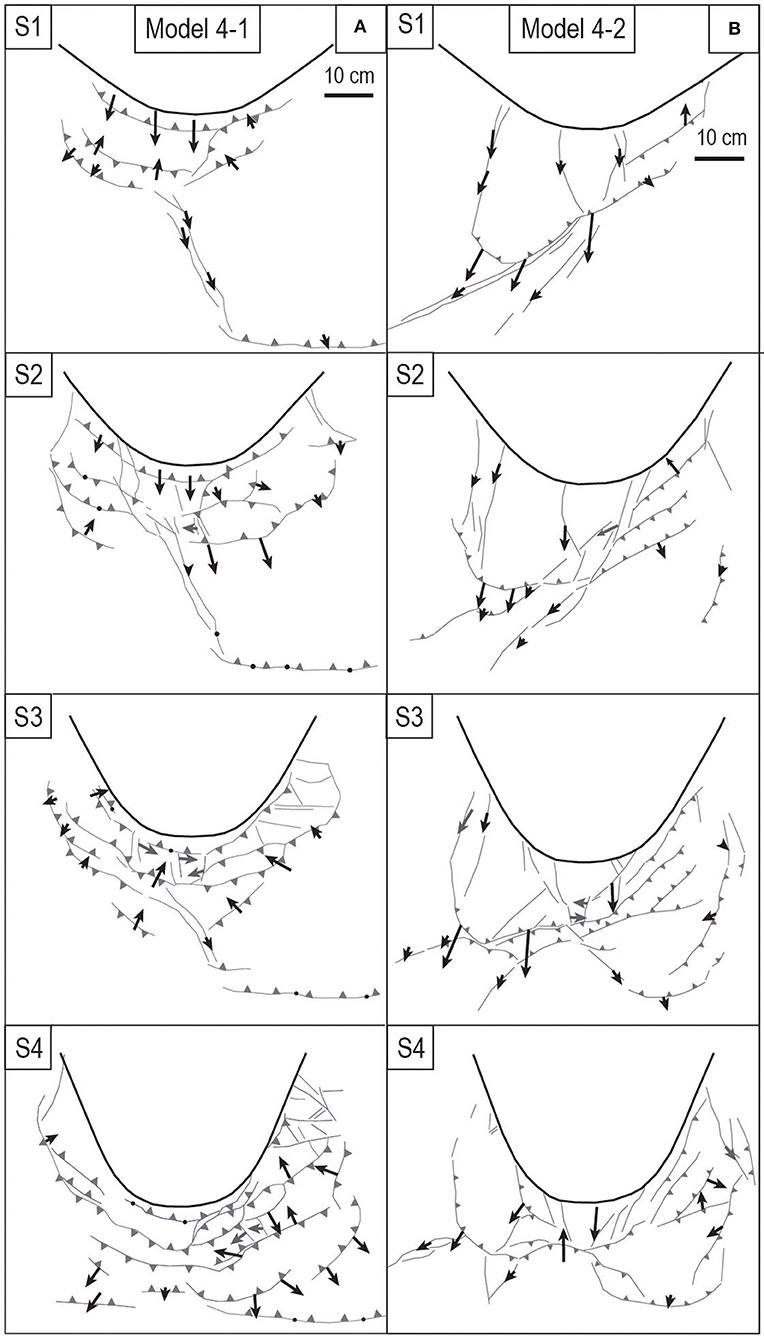
Figure 10. Displacement vectors associated with the main structures at the different stages of Models 4-1 (A) and 4-2 (B). The length of the arrows represents the magnitude of the displacement with the same scale of the line drawings. Black arrows: movement on thrust. Gray arrows: movement on normal fault. Other symbols: Idem Figures 6, 7.
Orocline Test
The orocline test assesses to what extent vertical-axis rotations have played a role in the acquisition of an orogen's curvature. It is graphically represented by the deflection of a primary, predeformational linear marker D, from a reference direction Dr, plotted against the deviation between the strike of regional structures S, and a reference strike Sr (Schwartz and Van der Voo, 1983; Weil and Sussman, 2004). Such D-Dr vs. S-Sr plots are represented in Figure 11.
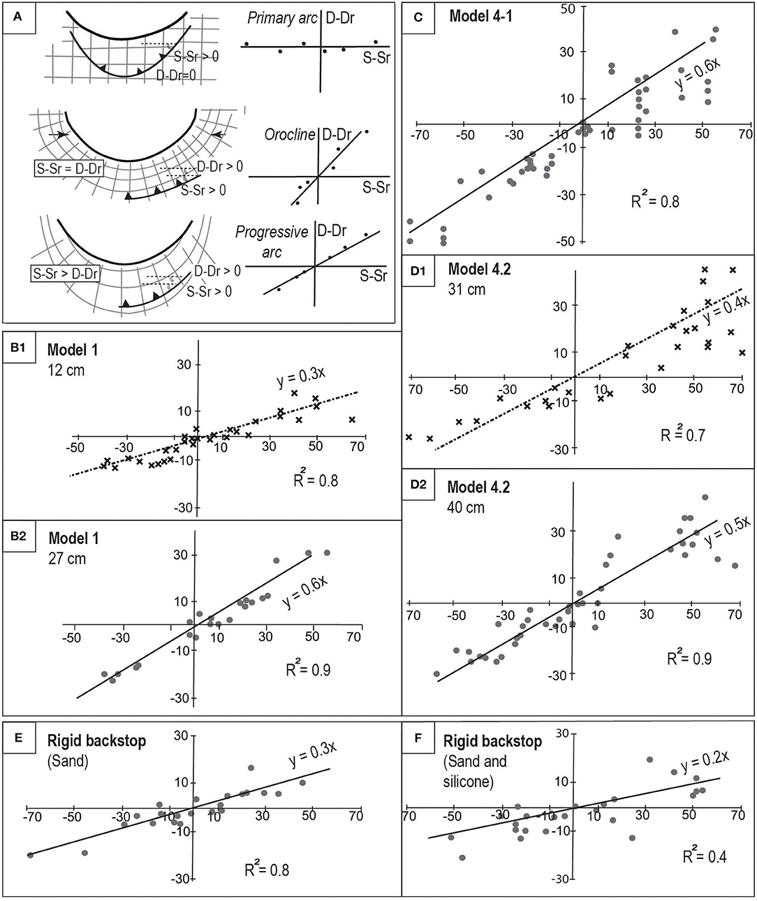
Figure 11. (A) Sketch of the paleomagnetical orocline test applied to our models. (B1, B2) Oroclinal test for Model 1 at early and final stages. (C) Oroclinal test for Model 4-1 at final stage. (D1, D2) Oroclinal test for Model 4-2 at early and final stage. (E,F) Oroclinal test for models of sand and silicone–sand of Crespo-Blanc and González-Sánchez (2005), respectively.
In natural cases, declination of paleomagnetical poles are used as the primary marker to quantify vertical-axis rigid body rotations, but others can be used, such as joints or paleocurrent directions (Weil et al., 2012). Such test can be applied to the analog models presented in this paper by using the grid markers as a proxy for paleomagnetical directions (see Costa and Speranza, 2003).
For the structures, the thrust traces drawn in the final stage of the experiments were divided into 3 cm-long segments and their mean orientation was measured. For both parameters, the E-W direction was used as the reference orientation, that is, the strike of the indenter in its undeformed stage. Thus, each point of the plots in Figure 11 represents the angle between the strike of the selected structure and the E-W direction (S-Sr) vs. the angle between the initial E-W lines of the grid marker closest to that structure and the E-W direction (D-Dr angle). If structures formed obliquely with respect to the E-W reference direction, but the grid did not rotate, oroclinal test will yield slopes around 0 (Figure 11A), corresponding to ideal primary arcs. By contrast, if both structures and grid markers rotated equally, slopes around 1 will be obtained, corresponding to ideal oroclinal arc. Slopes between 0 and 1 have been associated with progressive arcs (Weil et al., 2012).
This test has been applied to the final stages of sand model (Model 1) and large, sand–silicone models (Model 4-1 and Model 4-2), in order to test the influence of the presence of viscous substratum on the formation mechanism of the curved fold-and-thrust belts generated in our experiments (Figures 11B1, C,D1). The test was also applied at intermediate stages of Model 1 and Model 4-2 (Figures 11B2,D2). Moreover, for comparison purposes (see discussion), similar plots were made for two analog models of Crespo-Blanc and González-Sánchez (2005), with an elliptical, rigid backstop. One of them consisted of a sandpack (see Figure 3D), and the second one included a 0.5 cm silicone layer overlain by a 1.0 cm sand layer (see their Figure 4). These plots are presented in Figures 11E,F, respectively.
The slopes of the regression line yielded by the orocline tests for the final stages of our models vary between 0.5 and 0.6 (Figures 11 B1,C,D1). In Model 1 and Model 4-2, the slope is significantly smaller at intermediate stages (0.3 and 0.4, respectively; Figures 11B2,D2). In all cases, the linear regression is well-determined (R2 higher than 0.8). It is worth to note that in the two experiments with a rigid elliptical indenter, the oroclinal test yields much lower slope values (between 0.2 and 0.3; Figures 11E,F).
Discussion
Kinematics and Deformation Sequence of Analog Models
As described above, the progressive deformation caused by a backstop with increasing degree of protrusion and whose curvature ratio diminished with time indenting in a sand–silicone parallelepiped led to the formation of highly segmented arcuate fold-and-thrust belts. In both types of progressive arc models (with and without a viscous substratum), arc-perpendicular shortening was accommodated by radial outward thrusting, while arc-parallel lengthening was achieved by means of conjugated strike-slip fault systems and normal faults. Nevertheless, this strain partitioning mode varies significantly depending on the rheology of the initial analog pack. In the case of an initial sandpack, the geometry of the resulting arcuate thrust wedge is relatively simple (Figure 3). This sharply contrasts with the complex geometry of non-cylindrical thrusts and independent blocks rotating differentially that developed over a viscous substratum (Figures 5–7). In the next paragraphs, we will compare our results with other experiments that modeled arcuate fold-and-thrust belts with sand and silicone as analog materials.
Initial Sandpack
In our sandpack model (Model 1), the shortening mode is similar to the classical modeling of thrust wedges that developed in front of a straight, rigid indenter (Liu et al., 1992). It is achieved by foreland-verging thrusts rooted at the bottom of a sandpack in a piggyback sequence. In map view, the structural trend line of the final stage of Model 1 displays an arcuate geometry that mimics as a whole the indenter shape (Figure 3A). Moreover, a few structures accommodated arc lengthening. The displacement vectors along the frontal thrust structures are moderately divergent (Figure 3B).
Arcuate fold-and-thrust belts developed from sandpacks in front of rigid vertical indenters of different shapes and/or with a wide range of motion paths have been previously modeled. The final stages of selected ones are compiled in Figures 12A–F (this work; Marshak, 1988; Calassou et al., 1993; Zweigel, 1998; Lickorish et al., 2002; Crespo-Blanc and González-Sánchez, 2005, respectively).
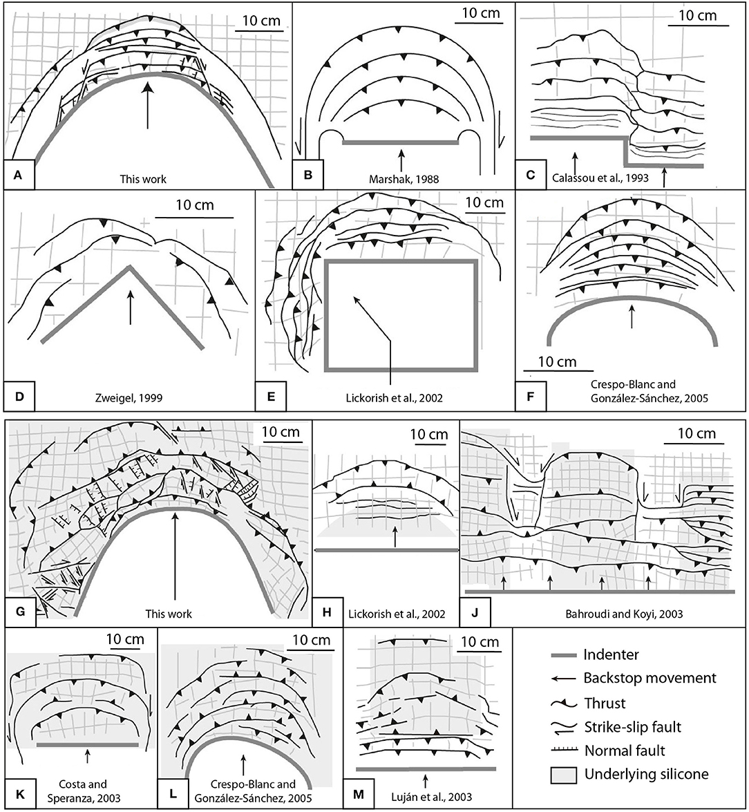
Figure 12. Line drawings of analog models of arcuate fold-and-thrust belts previously published compared with our results. (A–F) Sand models. (G–M) Silicone–sand models. References on the figure.
As in Model 1, rigid indenters simulating a primary arc with a step or with an angular or curved shape create curved thrust wedges with structural trend mimicking the indenter shape (Figures 12B–E). Nevertheless, such models differ from our Model 1 in the following characteristics: (a) the deformation took place only in front of the indenter (note that to generate folds and thrusts beyond the leading edge of the indenter, a curved displacement of the rigid indenter is necessary; Figure 12E); (b) the lateral boundaries of the deformed wedge are occupied by slumped areas, such that no thrusts form beyond these boundaries; (c) the overall transport direction of the thrusts is broadly parallel to the translation path of the indenter; (d) no significant arc-parallel lengthening occurred, and (e) the thrusts formed at early stages underwent only small vertical-axis rotations, if any.
Initial Sand–Silicone Pack
In our sand–silicone models, the propagation sequence of thrusts and backthrusts is characteristic of fold-and-thrust wedges developed over a viscous substratum, as modeled by other authors (e.g., Letouzey et al., 1995; Cotton and Koyi, 2000; Bahroudi and Koyi, 2003; Luján et al., 2003).
In the map view of our experiments, the deformed wedge acquired its arcuate geometry from the early stages of the experiments. The progressive indenter protrusion led to the formation of independent blocks, bounded by normal and/or strike-slip faults, which rotate differentially. These highly non-cylindrical structures together with the vertical-axis rotations are the identifying characteristics of the resulting fold-and-thrust belts (Figure 12G). This is favored by the localization of transpressive and transtensive zones. When compared with the final stages of selected sand–silicone models with rigid indenters, this is a striking difference. In the experiments of Lickorish et al. (2002), Bahroudi and Koyi (2003), Costa and Speranza (2003), Luján et al. (2003), and Crespo-Blanc and González-Sánchez (2005) (Figures 12H–M; respectively), the main factor that controls the curvature of the fold-and–thrust belts, regardless of the rigid indenter shape, is the geometry of the silicone layer in the initial analog pack. Moreover, rigid indenters with straight motion paths generate arcuate fold-and-thrust belts only in front of the indenter, whereas the lateral deformation zone around the indenter is very narrow (Figures 12J–M), as in models formed only by sand. Moreover, in these models with rigid indenter, the vertical-axis rotations are limited to a dozen degrees, if any (as in the model of Figures 12J,M).
In our sand–silicone models, we showed that the pattern of the displacement vectors on particular structures that contribute to the strain partitioning was rather complex both in space and time (Figures 5C,F, 10A,B). During the deformation sequence, the transport directions of thrusts and backthrusts were broadly radial, which contrasts with sand models (Figure 3). Moreover, several early formed structures progressively rotated, in such a way that the angle between the displacement vector and the strike of a particular rotating structure changed with time.
Even with a viscous substrate, it is not possible to generate a highly segmented arcuate wedge with a rigid indenter that moves with a straight motion path: a backstop with a variable protrusion grade and curvature ratio is needed. As such, strongly divergent displacement vectors in an arcuate fold-and-thrust wedge represent a solid argument for a progressive arc mode of formation.
Finally, it must be stressed that in our models, the buoyancy of the ductile layer is higher than in the natural cases (Table 1), which should have some influence on the experiment dynamics. Nevertheless, this behavior is assumed in most of the analog modeling set for the simulation of deformation in upper crustal levels (see models of Ferrer et al., 2016; Li and Mitra, 2017; Borderie et al., 2018; Roma et al., 2018 who used the same analog materials as in this paper). Moreover, at the beginning of our experiments, the lateral flow of the silicone was limited, as it was confined by sand. When deformation proceeds, silicone can flow toward zones of low-gravity potential and diapirs can eventually pierce the experiment surface.
Orocline Test Applied to the Analog Models
Concerning the orocline test applied to our models, the test values fall into the field of the progressive arcs, with slopes between 0.3 and 0.6 (Figure 11). This was expected, as our experimental setting included a deformable indenter to model progressive arcs. Nevertheless, it is remarkable that the test values increased as the experiments proceeded, approaching to orocline values (slope = 1). Indeed, they varied from 0.3–0.4 to 0.5–0.6, with both types of substratum (sand and silicone). This is a surprising tendency, as during the late stage of the experiments, the backstop acted close to a rigid indenter (fixed apex shape and minor limbs rotation), more similar to a primary arc. Accordingly, a decrease of the test slopes should be expected.
The increasing “oroclinal component” is also observed when this test is applied to previous experiments with a rigid indenter and a sand–silicone pack (Crespo-Blanc and González-Sánchez, 2005). In this case, the obtained values are lower (0.2–0.3) than those calculated for our experiments, but not equal to zero, which would represent an ideal primary arc. Consequently, our results suggest that the absolute values obtained from the orocline test alone may not be sufficient to distinguish between the formation modes of orogenic arcs if they are not compared to other kinematic information. In this sense, the analysis of the operating strain partitioning modes, and more specifically the amount and localization of arc-parallel stretching, seems to be a more useful and efficient approach (Hindle and Burkhard, 1999; Balanyá et al., 2007).
Comparison Between our Analog Models of Progressive Arcs, the Gibraltar Arc, and Other Natural Cases
Our experiments with a silicone layer systematically led to the formation of arcuate fold-and-thrust belts, which exhibit the following strain partitioning mode: (a) in cross section, the structural style is characterized by bivergent thrusts with pop-up and pop-down structures; (b) in map view, shortening in the external wedge was accommodated by thrusts with a pattern that broadly mimics the indenter curvature; (c) the displacement vectors along the thrusts define a fan, subperpendicular to the structural trend-line pattern at the hinge zone and oblique at the limbs; (d) normal and conjugate strike-slip faults, which accommodated arc-parallel stretching, contributed to the along-strike segmentation of the deformed wedge in blocks; (e) these blocks underwent clockwise and counterclockwise vertical-axis rotations of up to 65°, coherently with their position in the arc; and (f) major strike-slip dominated fault zones developed at the lateral parts of the arc.
The aforementioned strain partitioning mode of our models, both in cross section and map view, is very similar to that observed in the external zones of the Western Gibraltar Arc (Balanyá et al., 2007), which imposed our laboratory model setups in terms of rheology, convergence velocity around the progressive arc apex, arc chord line, and amplitude (degree of protrusion). In Table 3, we compare the main geological features of the Western Gibraltar Arc external fold-and-thrust belt of the northern branch with the main characteristics of our analog models, regarding transport direction, types and localization of structures, trend-line pattern, vertical-axis rotations, and size of the rotated blocks. We also include results from the model with a rigid indenter (Figure 3D) of Crespo-Blanc and González-Sánchez (2005). It must be stressed that we zoom on the northern branch of the Gibraltar Arc external wedge as its structural evolution is much better known than the southern one, and it is underlaid by a viscous substrate.
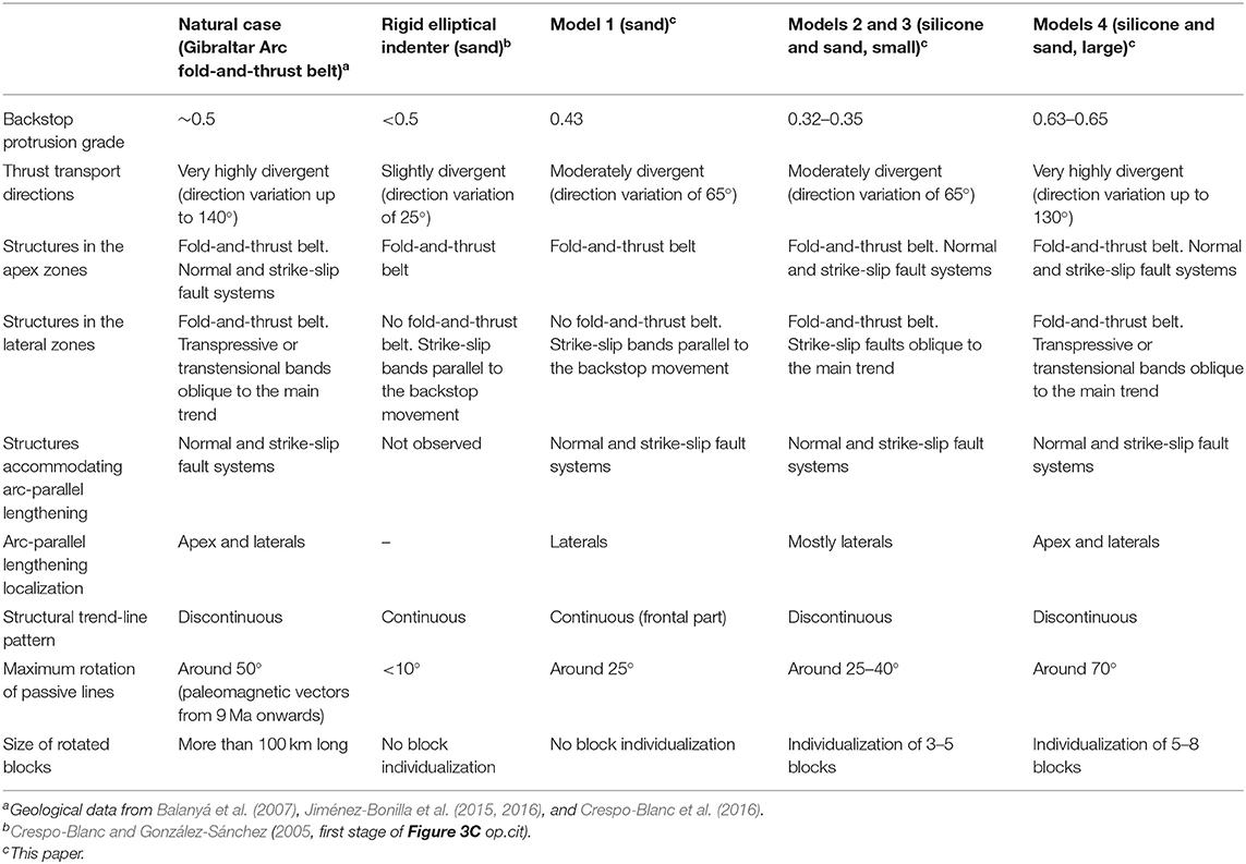
Table 3. Structural characteristics of the external wedge of the Gibraltar Arc system compared with those of our analog models.
Models 4-1 and 4-2 are those that best fit with the strain partitioning mode observed in the natural case (Table 3). In both the models and the natural case study: (1) the transport direction of thrusts swings significantly (up to 90° in the model and 130° in the natural case study, compare Figures 1B, 10); (2) arc-parallel stretching is accommodated by arc-perpendicular normal faults (e.g., the intermontane Ronda basin faults in Figure 1B; Jiménez-Bonilla et al., 2015) and conjugate strike-slip fault systems that localize cuspate recesses in map view (e.g., compare the Gaucín fault shown in Figure 1B with Figures 6, 7; Balanyá et al., 2007; Jiménez-Bonilla et al., 2015, 2016, 2017); (3) transpressive and transtensive bands developed oblique to the main trend at the lateral zones of the arcs, and likely contributed to their protrusion increase (compare the Torcal Shear Zone or Jebha fault in Figure 1B with Figures 6, 7, 8C,G; see also Barcos et al., 2015; Crespo-Blanc et al., 2018); and (4) independent blocks rotated significantly clockwise or counterclockwise related to their position at the right or left arc limbs, respectively.
The horizontal dimensions of independent blocks were 20-30 cm in the models, which, applying the scaling factor of 0.5 × 10⁻⁵ (Table 1), corresponds to 40–60 km in nature. This represents a block size about a half of the arc chord length, which is broadly the same magnitude of the four blocks described by Crespo-Blanc et al. (2016) in the Gibraltar Arc System, which are 100–200 km long (measured along-strike, that is 0.5–1 time the arc chord length). In the natural case, these blocks rotated in the same sense as our experiments during the last 9 Ma, and the maximum amount of rotation of passive lines observed in the Gibraltar Arc System (53° in the western Betics block) is similar to the maximum rotations observed in models with a silicone layer (Models 2–4). For all these reasons, the development of an arcuate fold-and-thrust belt such as the Gibraltar Arc external wedge is likely similar to the models of progressive arc described in this paper.
Other natural examples of Mediterranean progressive arcs could have formed in a comparable way in terms of kinematics and strain partitioning as the Calabrian or the Carpathian Arcs (Figure 1A). As the Gibraltar Arc, these arcs formed in convergent systems in which outward radial thrusting is coupled with severe back-arc extension. A significant increase in the area and perimeter of their internal zones took place while these latter pushed from behind and intruded progressively the external fold-and-thrust belts (Horvath and Berkhemer, 1982). Both arcs also show similar chord line lengths measured at the external–internal zone boundary (ca. 185–290 km) and degree of protrusion (0.4–0.5) with respect to the Gibraltar Arc (Figure 1C).
Onshore, the limbs of the emerged Calabrian arc are composed by the fold-and-thrust belts of the Sicilian Maghrebides to the southwest and of the Southern Apennines to the northeast, related to the African and Adriatic continental margins, respectively. Offshore, in the outer part of the apex zone of the arc, a submerged accretionary prism developed (Polonia et al., 2011). Cifelli et al. (2008, 2016) show that blocks ca. 200 km long rotated clockwise and counterclockwise in the NE and SW arc limbs, respectively. In the Southern Apennines, these vertical-axis rotations measured from middle-upper Miocene can reach 100° (Patacca et al., 1990; Scheepers and Langereis, 1994; Maffione et al., 2013), having rotated up to 56° in the last 9 Ma, a similar rotation as the Models 2–4 (Cifelli et al., 2008, 2016; Figure 1D). Moreover, these rotations are accompanied by normal faulting, associated with arc-parallel stretching and responsible for the development of several intermontane basins (Aucelli et al., 2014), which is also observable in Models 2–4. Nevertheless, it must be stressed that the rheological profile of the Sicilian-Maghrebides and the Southern Apennines fold-and-thrust belt of the Calabrian Arc differ from the Gibraltar Arc. Indeed, neither the fold-and-thrust belt of the Sicilian Maghrebides nor that of the Southern Apennines detached over evaporites.
In the same way, in the Carpathian Arc external wedge, the strike of the folds and thrusts associated with arc-perpendicular shortening varies ~125°, from NW-SE in the northeastern part of the arc to E-W in the southern one (Linzer, 1996; Figure 1E). The transport directions along the thrusts fan around the arc ca. 90°, that is, a significantly smaller angle than their strike variation. This differs from the models with silicone layer, but is similar to the first stages of the sand models (Figure 3C). As a matter of fact, the basal layer in the external Carpathian Arc is not composed of evaporites, as reported in the Gibraltar Arc northern branch, but of lutites, weaker than other sedimentary rocks although still with a brittle behavior. Major strike-slip shear zones develop at low angles to the structural trend in the lateral parts of the Carpathian arc: sinistral wrench faults in the northern branch (Linzer, 1996) and a large-scale dextral transpressive zone to the south in which displacement is partitioned into thrust shear, pure shear distributed deformation, and dextral wrench shear (Ratschbacher et al., 1993). Finally, Cretaceous to lower Miocene paleomagnetical declinations reveal severe differential rotations (more than 90°) fanning outwards around the entire Carpathian arc. Zooming in the eastern Carpathian salient, these rotations are predominantly of dextral sense and reach 60°, although they were accomplished during various events from the very beginning of the arching (Linzer, 1996). In Figure 1E, only the last vertical axis rotational event has been indicated.
Conclusions
1. The analog experiments presented here model the progressive deformation of analog packs in front of an indenter that moved toward the foreland with an increasing degree of protrusion and whose curvature ratio diminished with time, that is, a progressive arc. The experiments led to the formation of arcuate fold-and-thrust belts in which strain was partitioned between: (a) arc-perpendicular shortening accommodated by thrusts with slightly divergent (sand) or approximately radial outward transport direction (sand–silicone), and (b) arc-parallel stretching accommodated by both normal and conjugate strike-slip faults, which would lead, in natural progressive arcs, to the development of intermontane basins. Such strain partitioning occurred from the very beginning of the experiments.
2. In the experiments with a silicone lower layer, normal and strike-slip faults, developed mainly in the lateral parts of the arcs, contributed to the along-strike fold-and-thrust belt segmentation in blocks, resulting in a highly non-cylindrical arcuate wedge. These blocks suffered clockwise and counterclockwise rotation (up to 65°) in the right and left flanks of the progressive arc, respectively (referenced to the direction of apex movement). The kinematics of the structures that separate blocks were complex and varied with time. By contrast, models that employed only sand generated an arcuate piggyback forethrust sequence, which was extended along strike by somewhat evenly distributed normal faults.
3. In fold-and-thrust wedges over a frictional decollement (sandpack), the tectonic transport associated with thrusting shows a slightly divergent pattern and is relatively constant during progressive deformation. By contrast, in the sand–silicone experiments, the displacement vectors along particular thrusts display a radial pattern swinging ~90° from one part to the other of the indenter symmetry axis. As deformation proceeded, most structures rotated clockwise or counterclockwise and the angle between their strikes and their displacement vectors changed with time. Hence, the tectonic regime of some faults significantly changed during the experiments.
4. Orocline tests applied to our models yielded values that are consistent with those of progressive arcs. As the degree of protrusion of the indenter increases, the test values approached orocline values, even though primary arc values would have been expected.
5. The strain partitioning mode in our progressive arc models is similar to that observed in the external zones of the northern branch of the Gibraltar Arc System in terms of degree of protrusion, transport directions, types and localization of the structures, trend-line pattern and vertical-axis rotations. Other two natural cases of the Mediterranean arcs that developed during a thin-skinned regime are similar to our analog models. Although the natural case studies are more complex due to intrinsic heterogeneities (e.g., variations of the rheology of the decollement level, variations in the ratio of competent/weak rock thickness, a.s.o.), analog modeling of progressive arcs with a deformable backstop in map view can be used to shed light on the type and kinematics of the structures that develop during progressive development of arcuate fold-and-thrust belts.
Data Availability Statement
All datasets generated for this study are included in the article/Supplementary Material.
Author Contributions
AJ-B and AC-B realized the experiments. JB, IE, and MD-A help to conceived the experiments. All of us participated to the manuscript redaction.
Funding
This study was supported by projects RNM-0451, EST1/00231, CGL2017-89051-P, PGC2018-100914-B-I00, and UPO 1259543.
Conflict of Interest
The authors declare that the research was conducted in the absence of any commercial or financial relationships that could be construed as a potential conflict of interest.
Supplementary Material
The Supplementary Material for this article can be found online at: https://www.frontiersin.org/articles/10.3389/feart.2020.00072/full#supplementary-material
Supplementary Video 1. Small sandpack composed only by sand (Model 1).
Supplementary Video 2. Small sandpack with silicone substratum (Model 2).
Supplementary Video 3. Small sandpack with silicone substratum (Model 3).
Supplementary Video 4. Large sandpack with silicone substratum (Model 4-1).
Supplementary Video 5. Large sandpack with silicone substratum (Model 4-2).
References
Aucelli, P., D'Argenio, B., Della Seta, M., Giano, S. I., and Schiattarella, M. (2014). Foreword: intermontane basins: quaternary morphoevolution of Central-Southern Italy. Red. Fis. Acc. Lincei 25, 107–110. doi: 10.1007/s12210-014-0356-3
Bahroudi, A., and Koyi, H. A. (2003). Effect of spatial distribution of Hormuz salt on deformation style in the Zagros fold and thrust belt: an analogue modelling approach. J. Geol. Soc. Lond. 160, 719–733. doi: 10.1144/0016-764902-135
Balanyá, J. C., Crespo-Blanc, A., Díaz Azpiroz, M., Expósito, I., and Luján, M. (2007). Structural trend line pattern and strain partitioning around the Gibraltar Arc accretionary wedge: insights as to the mode of orogenic arc building. Tectonics 26:TC2005. doi: 10.1029/2005TC001932
Balanyá, J. C., Crespo-Blanc, A., Díaz-Azpiroz, M., Expósito, I., Torcal, F., Pérez-Peña, V., et al. (2012). Arc-parallel vs back-arc extension in the Western Gibraltar arc: is the Gibraltar forearc still active? Geol. Acta 10, 249–263. doi: 10.1344/105.000001771
Barcos, L., Balanyá, J. C., Díaz-Azpiroz, M., Expósito, I., and Jiménez-Bonilla, A. (2015). Kinematics of the Torcal Shear Zone: transpressional tectonics in a salient-recess transition at the northern Gibraltar Arc. Tectonophysics 663, 62–77. doi: 10.1016/j.tecto.2015.05.002
Bonini, M. (2001). Passive roof thrusting and forelandward fold propagation in scaled brittle-ductile physical models of thrust wedges. J. Geophys. Res. 106, 2291–2311. doi: 10.1029/2000JB900310
Borderie, S., Graveleau, F., Witt, C., and Vendeville, B. (2018). Impact of an interbedded viscous décollement on the structural and kinematic coupling in fold-and-thrust belts: insights from analogue modelling. Tectonophysics 722, 118–137. doi: 10.1016/j.tecto.2017.10.019
Calassou, S., Larroque, C., and Malavieille, J. (1993). Transfer zones of deformation in thrust wedges: an experimental study. Tectonophysics 221, 325–344. doi: 10.1016/0040-1951(93)90165-G
Chalouan, A., Michard, A., El Kadiri, K., Negro, F., Frizon de Lamotte, D., Soto, J. I., et al. (2008). “The Rif belt,” in Continental Evolution: The Geology of Morocco. Lecture Notes in Earth Sciences, eds A. Michard, O. Saddiqi, A. Chalouan, and D. Frizon de Lamotte (Berlin: Springer-Verlag), 116. doi: 10.1007/978-3-540-77076-3_5
Cifelli, F., Caricchi, C., and Mattei, M. (2016). “Formation of arc-shaped orogenic belts in the Western and Central Mediterranean: a palaeomagnetic review,” in Palaeomagnetism in Fold and Thrust Belts: New, eds E. L. Pueyo, F. Cifelli, A. J. Sussman, and B. Oliva-Urcia (London: Special Publications; Geological Society), 425. doi: 10.1144/SP425.12
Cifelli, F., Mattei, M., and Porreca, M. (2008). New paleomagnetic data from Oligocene-upper Miocene sediments in the Rif chain (northern Morocco): insights on the Neogene tectonic evolution of the Gibraltar arc. J. Geophys. Res. B: Solid Earth 113:B02104. doi: 10.1029/2007JB005271
Comas, M. C., Platt, J. P., Soto, J. I., and Watts, A. B. (1999). “The origin and tectonic history of the Alborán basin: insights from Leg 161 results,” in Proceeding of the Ocean Drilling Program, Scientific Results, Vol. 161, eds R. Zahn, M. C. Comas, and A. Klaus (College Station, TX), 555–579. doi: 10.2973/odp.proc.sr.161.262.1999
Corrado, S., Di Bucci, D., Naso, G., and Faccenna, C. (1998). Influence of palaeogeography on thrust system geometries: an analogue modelling approach for the Abruzzi-Molise (Italy) case history. Tectonophysics 296, 437–453. doi: 10.1016/S0040-1951(98)00147-4
Costa, E., and Speranza, F. (2003). Paleomagnetic analysis of curved thrust belts reproduced by physical models. J. Geodyn. 36, 633–654. doi: 10.1016/j.jog.2003.08.003
Cotton, J., and Koyi, H. (2000). Modeling of thrust front above ductile and frictional detachments: application to structures in the Salt Range and Potwar Plateau, Pakistan. Geol. Soc. Am. Bull. 112–113, 351–363. doi: 10.1130/0016-7606(2000)112<351:MOTFAD>2.0.CO;2
Crespo-Blanc, A. (2007). Superposed folding and oblique structures in the paleomargin–derived units of the Central Betics (SW Spain). J. Geol. Soc. Lond. 164, 621–636. doi: 10.1144/0016-76492006-084
Crespo-Blanc, A. (2008). Recess drawn by the internal zone outer boundary and oblique structures in the paleomargin-derived units (Subbetic domain, central Betics): an analogue modelling approach. J. Struct. Geol. 30, 65–80. doi: 10.1016/j.jsg.2007.09.009
Crespo-Blanc, A., Balanyá, J. C., Expósito, I., Luján, M., and Suades, E. (2012). Crescent-like large scale structures in the external zones of the western Gibraltar arc (Betic–Rif orogenic wedge). J. Geol. Soc. Lond. 169, 667–679. doi: 10.1144/jgs2011-115
Crespo-Blanc, A., and Campos, J. (2001). Structure and kinematics of the South Iberian paleomargin and its relationship with the flysch trough units: extensional tectonics within the Gibraltar Arc fold-and-thrust belt (western Betics). J. Struct. Geol. 23, 1615–1630. doi: 10.1016/S0191-8141(01)00012-8
Crespo-Blanc, A., Comas, M., and Balanyá, J. C. (2016). Clues for a Tortonian reconstruction of the Gibraltar Arc: structural pattern, deformation diachronism and block rotations. Tectonophysics 683, 308–324. doi: 10.1016/j.tecto.2016.05.045
Crespo-Blanc, A., and González-Sánchez, A. (2005). Influence of indenter geometry on arcuate fold-and-thrust wedge: preliminary results of analogue modeling. Geogaceta 37, 11–14.
Crespo-Blanc, A., Jiménez-Bonilla, A., Balanyá, J. C., Expósito, I., and Díaz-Azpiroz, M. (2018). Models going through analogue experiments: the Gibraltar Arc System revisited in the light of the External Zones structural evolution. Revista de la Sociedad Geológica de España 31, 23–51.
Dominguez, S., Malavieille, J., and Lallemand, S. E. (2000). Deformation of accretionary wedge in response to seamount subduction: insight from sandbox experiments. Tectonics 19, 182–196. doi: 10.1029/1999TC900055
Duarte, J. C., Rosas, F. M., Terrinha, P., Gutscher, M. A., Malavieille, J., Silva, S., et al. (2011). Thrust–wrench interference tectonics in the Gulf of Cadiz (Africa–Iberia plate boundary in the North-East Atlantic): insights from analogue models. Marine Geol. 289, 135–149. doi: 10.1016/j.margeo.2011.09.014
Eldredge, S., Bachtadse, V., and van der Voo, R. (1985). Paleomagnetism and the orocline hypothesis. Tectonophysics 119, 153–179. doi: 10.1016/0040-1951(85)90037-X
Expósito, I., Balanyá, J. C., Crespo-Blanc, A., Díaz-Azpiroz, M., and Luján, M. (2012). Overthrust shear folding and contrasting deformation styles in a multiple decollement setting, Gibraltar Arc external wedge. Tectonophysics 576–577, 86–98. doi: 10.1016/j.tecto.2012.04.018
Ferrer, O., McKaly, K., and Sellier, N. C. (2016). “Influence of fault geometries and mechanical anisotropies on the growth and inversion of hanging-wall synclinal basins: insights from sandbox models and natural examples,” in The Geometry and Growth of Normal Faults, eds C. Childs, R. E. Holdsworth, C. A.-L. Jackson, T. Manzocchi, J. J. Walsh, and G. Yielding (London: Special Publications; Geological Society) 439. doi: 10.1144/SP439.8
Funiciello, F., Faccenna, C., Giardini, D., and Regenauer-Lieb, K. (2003). Dynamics of retreating slabs: 2. Insights from three-dimensional laboratory experiments. J. Geophys. Res. 108, 1–16. doi: 10.1029/2001JB000896
Gutscher, M.-A., Kopp, H., Krastel, S., Bohrmann, G., Garlan, T., Zaragosi, S., et al. (2017). Active tectonics of the Calabrian subduction revealed by new multi-beam bathymetric data and high-resolution seismic profiles in the Ionian Sea (Central Mediterranean). Earth Planet. Sci. Lett. 461, 61–72. doi: 10.1016/j.epsl.2016.12.020
Hindle, D., and Burkhard, M. (1999). Strain, displace¬ment and rotation associated with the formation of curvature in fold belts: the example of the Jura Arc. J. Struct. Geol. 21, 1089–1101. doi: 10.1016/S0191-8141(99)00021-8
Horvath, F., and Berkhemer, H. (1982). “Mediterranean backarc basins,” in Alpine Mediterranean Geodynamics, eds H. Berkhemer and M. Hsü (Washington, DC: American Geophysics Union), 141–173. doi: 10.1029/GD007p0141
Jiménez-Bonilla, A., Expósito, I., Balanyá, J. C., and Díaz-Azpiroz, M. (2017). Strain partitioning and relief segmentation in arcuate fold-and-thrust belts: a case study from the western Betics. J. Iberian Geol. 43, 497–518. doi: 10.1007/s41513-017-0028-0
Jiménez-Bonilla, A., Expósito, I., Balanyá, J. C., Díaz-Azpiroz, M., and Barcos, L. (2015). The role of strain partitioning on intermontane basin inception and isolation, External Western Gibraltar Arc. J. Geodyn. 92, 1–17. doi: 10.1016/j.jog.2015.09.001
Jiménez-Bonilla, A., Torvela, T., Balanyá, J. C., Expósito, I., and Díaz-Azpiroz, M. (2016). Changes in dip and frictional properties of the basal detachment controlling orogenic wedge propagation and frontal collapse: the external central betics case. Tectonics 35, 3028–3049. doi: 10.1002/2016TC004196
Johnston, S. T., Weil, A. B., and Gutiérrez-Alonso, G. (2013). Oroclines: thick and thin. Geol. Soc. Am. Bull. 125, 643–663. doi: 10.1130/B30765.1
Letouzey, J., Colletta, B., Vially, R., and Chermette, J. C. (1995). “Evolution of salt related structures in compressional setting,” in Salt Tectonics: A Global Perspective, eds M. P. A. Jackson, D. G. Roberts, and S. Snelson (Tulsa: AAPG Mem), 65, 41–60. doi: 10.1306/M65604C3
Li, J., and Mitra, S. (2017). Geometry and evolution of fold-thrust structures at the boundaries between frictional and ductile detachments. Mar. Pet. Geol. 85, 16–34. doi: 10.1016/j.marpetgeo.2017.04.011
Lickorish, W. H., Ford, M., Bürgisser, J., and Cobbold, P. (2002). Arcuate thrust systems produced by sand-box modelling: a comparison to the external arc of the Western Alps. Geol. Soc. Am. Bull. 114, 1089–1107.
Linzer, H. G. (1996). Kinematics of Retreating Subduction along the Carpathian Arc, Romania. Geology 24, 167–170. doi: 10.1130/0091-7613(1996)024<0167:KORSAT>2.3.CO;2
Liu, H., McClay, K. R., and Powell, D. (1992). “Physical models of thrust wedges,” in Thrust Tectonics, ed K. R. McClay (London, UK; New York, NY; Tokyo; Melbourne, VIC; Madras: Chapman and Hall), 71–81. doi: 10.1007/978-94-011-3066-0_6
Lu, C. Y., and Malavieille, J. (1994). Oblique convergence, indentation and rotation tectonics in the Taiwan Mountain Belt: insights from experimental modelling. Earth Planet. Sci. Lett. 121, 477–494. doi: 10.1016/0012-821X(94)90085-X
Luján, M., Crespo-Blanc, A., and Balanyá, J. C. (2006a). The Flysch Trough thrust imbricate (Betic Cordillera): a key element of the Gibraltar Arc orogenic wedge. Tectonics 25, 1–17. doi: 10.1029/2005TC001910
Luján, M., Storti, F., Balanyá, J. C., Crespo-Blanc, A., and Rossetti, F. (2003). Role of décollement material with different rheological properties in the structure of the Aljibe thrust imbricate (Flysch Trough, Gibraltar Arc): an analogue modelling approach. J. Struct. Geol. 25, 867–881. doi: 10.1016/S0191-8141(02)00087-1
Luján, M., Storti, F., Rossetti, F., and Crespo-Blanc, A. (2006b). Extrusion vs. accretion at the frictional-viscous décollement transition in experimental thrust wedges: the role of convergence velocity. Terra Nova 18, 241–247. doi: 10.1111/j.1365-3121.2006.00685.x
Macedo, J., and Marshak, S. (1999). Controls on the geometry of fold-thrust belt salients. Geol. Soc. Am. Bull. 111, 1808–1822. doi: 10.1130/0016-7606(1999)111<1808:COTGOF>2.3.CO;2
Maffione, M., Speranza, F., Cascella, A., Longhitano, S. G., and Chiarella, D. (2013). A 125° post-early Serravallian counterclockwise rotation of the Gorgoglione Formation (Southern Apennines, Italy): new constraints for the formation of the Calabrian Arc. Tectonophysics 590, 24–37. doi: 10.1016/j.tecto.2013.01.005
Marques, F. O., and Cobbold, P. R. (2002). Topography as a major factor in the development of arcuate thrust belts: insights from sandbox experiments. Tectonophysics 348, 247–268. doi: 10.1016/S0040-1951(02)00077-X
Marshak, S. (1988). Kinematics of orocline and arc formation in thin-skinned orogens. Tectonics 7, 73–86. doi: 10.1029/TC007i001p00073
Marshak, S. (2004). “Salients, recesses, arcs, oroclines, and syntaxes; a review of ideas concerning the formation of map-view curves in fold-thrust belts,” in Thrust Tectonics and Hydrocarbon Systems, ed K. R. McClay (AAPG Memoir) 82, 131–156.
Marshak, S., and Wilkerson, M. S. (1992). Effect of overburden thickness on thrust belt geometry and development. Tectonics 11, 560–566. doi: 10.1029/92TC00175
Marshak, S., Wilkerson, M. S., and Hsui, A. T. (1992). “Generation of curved fold–thrust belts: insight from simple physical and analytical models,” in Thrust Tectonics, ed K. R. McClay (London: Chapman and Hall), 83–92. doi: 10.1007/978-94-011-3066-0_7
Mitra, G. (1997). “Evolution of salients in a fold-and-thrust belt: the effects of sedimentary basin geometry, strain distribution and critical taper,” in Evolution of Geological Structures in Micro- to Macroscales. ed S. Sengupta (London: Chapman & Hall), 59–90. doi: 10.1007/978-94-011-5870-1_5
Mukherjee, S., Talbot, C. J., and Koyi, H. (2010). Viscosity estimates of salt in the Hormuz and Namakdan salt diapirs, Persian Gulf. Geol. Mag. 147, 297–507. doi: 10.1017/S001675680999077X
Musgrave, R. J. (2015). Oroclines in Tasmanides. J. Struct. Geol. 80, 72–98. doi: 10.1016/j.jsg.2015.08.010
Patacca, E., Sartori, R., and Scandone, P. (1990). Tyrrhenian Basin and appeninic Arcs: kinematic relations since late tortonian times. Mem. Soc. Geol. Ital. 45, 425–451.
Polonia, A., Torelli, L., Mussoni, P., Gasperini, L., Artoni, A., and Klaeschen, D. (2011). The Calabrian Arc subduction complex in the Ionian Sea: regional architecture, active deformation, and seismic hazard. Tectonics 30:5018. doi: 10.1029/2010TC002821
Ratschbacher, L., Frisch, W., and Linzer, H. G. (1993). The Pieniny Klippen Belt in the Western Carpathians of northeastern Slovakia, structural evidence for transpression. Tectonophysics 226, 471–483. doi: 10.1016/0040-1951(93)90133-5
Rauch, M. (2013). The oligocene–miocene tectonic evolution of the northern outer carpathian fold-and-thrust belt: insights from compression-and-rotation analogue modelling experiments. Geol. Mag. 150, 1062–1084. doi: 10.1017/S0016756813000320
Reiter, K., Kukowski, N., and Ratschbacher, L. (2011). The interaction of two indenters in analogue experiments and implications for curved fold-and-thrust belts. Earth Planet. Sci. Lett. 302, 132–146. doi: 10.1016/j.epsl.2010.12.002
Roma, M., Ferrer, O., Roca, E., Pla, O., Escosa, O., and Butillé, M. (2018). Formation and inversion of salt detached ramp-syncline basins. Results from analog modeling and application to the Columbrets Basin (Western Mediterranean). Tectonophysics 745, 214–228. doi: 10.1016/j.tecto.2018.08.012
Sadeghi, S., Storti, F., Yassaghi, A., Nestola, Y., and Cavozzi, C. (2016). Experimental deformation partitioning in obliquely converging orogens with lateral variations of basal décollement rheology: Inferences for NW Zagros, Iran. Tectonophysics 693, 223–238. doi: 10.1016/j.tecto.2016.05.014
Scheepers, P. J. J., and Langereis, C. G. (1994). Magnetic fabric of the Pleistocene clays from the Tyrrhenian arc: a magnetic lineation induced in the final stage of the middle Pleistocene compressive event. Tectonics 13, 1190–1200. doi: 10.1029/94TC00221
Schellart, W., and Strak, V. (2016). A review of analogue modelling of geodynamic processes: approaches, scaling, materials and quantification, with an application to subduction experiments. J. Geodyn. 100, 7–32. doi: 10.1016/j.jog.2016.03.009
Schreurs, G., Haenni, R., and Vock, P. (2001). Four-dimensional analysis of analog models; experiments on transfer zones in fold and thrust belts. Mem. Geol. Soc. Am. 193, 179–190. doi: 10.1130/0-8137-1193-2.179
Schwartz, S. Y., and Van der Voo, R. (1983). Palaeomagnetic evaluation of the orocline hypothesis in the central and southern Appalachians. Geophys. Res. Lett. 10, 505–508. doi: 10.1029/GL010i007p00505
Sherkati, S., Molinaro, M., Frizon de Lamotte, D., and Letouzey, J. (2005). Detachment folding in the Central and Eastern Zagros fold-belt (Iran): salt mobility, multiple detachments and late basement control. J. Struct. Geol. 27, 1680–1696. doi: 10.1016/j.jsg.2005.05.010
Soto, R., Casas, A. M., Storti, F., and Faccenna, C. (2002). Role of lateral thickness variations on the development of oblique structures at the Western end of the South Pyrenean Central Unit. Tectonophysics 350, 215–235. doi: 10.1016/S0040-1951(02)00116-6
Storti, F., Soto Marín, R., Rossetti, F., and Casas Sainz, A. M. (2007). Evolution of experimental thrust wedges accreted from along-strike tapered, silicone-floored multilayers. J. Geol. Soc. 164, 73–85. doi: 10.1144/0016-76492005-186
Ter Borgh, M. M., Oldenhuis, R., Biermann, C., Smit, J. H. W., and Sokoutis, D. (2011). The effects of basement ramps on deformation of the Prebetics (Spain): a combined field and analogue modelling study. Tectonophysics 502, 62–74. doi: 10.1016/j.tecto.2010.04.013
Vera, J. A. (Eds.). (2004). Geología de España. Madrid: Sociedad Geológica de España; Instituto Geológico y Minero de España.
Weijermars, R., Jackson, M. P. A., and Vendeville, B. (1993). Rheological and tectonic modeling of salt provinces. Tectonophysics 217, 143–174. doi: 10.1016/0040-1951(93)90208-2
Weijermars, R., and Schmeling, H. (1986). Scaling of Newtonian and non-Newtonian fluid dynamics without inertia for quantitative modelling of rock flow due to gravity (including the concept of rheological similarity). Phys. Earth Planet. In. 43, 316–330. doi: 10.1016/0031-9201(86)90021-X
Weil, A., Gutiérrez-Alonso, G., Johnston, S. T., and Pastor-Galán, D. (2012). Kinematic constraints on buckling a lithospheric-scale orocline along the northern margin of Gondwana: a geologic synthesis: Tectonophysics 582, 25–49. doi: 10.1016/j.tecto.2012.10.006
Weil, A. B., and Sussman, A. J. (2004). Classifying curved orogens based on timing relationships between structural development and vertical-axis rotations. Geol. Soc. Am. 383, 1–15. doi: 10.1130/0-8137-2383-3(2004)383[1:CCOBOT]2.0.CO;2
Weil, A. B., Yonkee, A., and Sussman, A. (2010). Reconstructing the kinematic evolution of curved mountain belts: internal strain patterns in the Wyoming Salient, Sevier thrust belt, U.S.A. Geol. Soc. Am. Bull. 122, 3–23. doi: 10.1130/B26483.1
Wu, J., McClay, K., and Frankowicz, E. (2015). Niger Delta gravity-driven deformation above the relict Chain and Charcot oceanic fracture zones, Gulf of Guinea: insights from analogue models. Mar. Petrol. Geol. 65, 43–62. doi: 10.1016/j.marpetgeo.2015.03.008
Keywords: analog model, progressive arc, thin-skinned tectonics, strain partitioning, block rotation, Gibraltar Arc external wedge
Citation: Jiménez-Bonilla A, Crespo-Blanc A, Balanyá JC, Expósito I and Díaz-Azpiroz M (2020) Analog Models of Fold-and-Thrust Wedges in Progressive Arcs: A Comparison With the Gibraltar Arc External Wedge. Front. Earth Sci. 8:72. doi: 10.3389/feart.2020.00072
Received: 10 December 2019; Accepted: 26 February 2020;
Published: 31 March 2020.
Edited by:
Valerio Acocella, Roma Tre University, ItalyReviewed by:
Marco Bonini, Italian National Research Council, ItalyAntonio Casas, University of Zaragoza, Spain
Copyright © 2020 Jiménez-Bonilla, Crespo-Blanc, Balanyá, Expósito and Díaz-Azpiroz. This is an open-access article distributed under the terms of the Creative Commons Attribution License (CC BY). The use, distribution or reproduction in other forums is permitted, provided the original author(s) and the copyright owner(s) are credited and that the original publication in this journal is cited, in accordance with accepted academic practice. No use, distribution or reproduction is permitted which does not comply with these terms.
*Correspondence: Alejandro Jiménez-Bonilla, ajimbon@upo.es