Retaining Technology for Deep Foundation Pit Excavation Adjacent to High-Speed Railways Based on Deformation Control
 Guohui Wang
 Wenhua Chen1
 - 1School of Civil Engineering, Beijing Jiaotong University, Beijing, China
- 2Xinfa Group Co., Ltd., Jinan, China
- 3Hebei Research Institute of Construction and Geotechnical Investigation Co., Ltd., Shijiazhuang, China
Considering the deep foundation pit of a car dumper room close to the Beijing–Baotou railway, the countermeasures of the foundation pit design are analyzed according to the surrounding environment and stratum conditions. Through Midas GTS software as well as field measured results, the construction effect on the adjacent railway subgrade is discussed. Therefore, the deformation characteristics of the foundation pit as well as the retaining structure, including the railway subgrade, caused by the excavation process, are revealed. The results show that the five-sided water-stop structure formed by cement piles around and at the bottom of the pit avoids the consolidation settlement of the adjacent railway subgrade caused by deep dewatering and also reduces the lateral displacement (i.e., in a horizontal direction) and the heave of the pit bottom. As a result, the lateral displacement near the railway side is larger than that of the retaining structure on the other side due to the subgrade on the pit side. The cross-lot bracing across the foundation pit will transfer the bias pressure of the subgrade to the retaining structure far away from the railway, while the transfer effect of the knee bracing is not obvious. The deformation of the railway subgrade and its evolution rate caused by the removal of internal bracing is significantly greater than the subgrade deformation and the change rate of deformation caused by excavation. The research results provide useful guidance for the deep foundation pit design.
Introduction
With the increased development of urbanization construction, there are increasing foundation pit projects near the existing structures in recent years (Seong et al., 2011; Zhang et al., 2018; Li et al., 2020). Due to complicated environmental factors, including external applied force (Guo et al., 2019; Rashidi and Shahir, 2019), soil microstructure, and temperature application due to external environments (Bai, 2013; Bai et al., 2019a), the building environment around the deep foundation pit causes soil disturbance (Li et al., 2019; Pathirana et al., 2019). However, the ability of roads to resist differential settlement is limited. Once the deformation of buildings adjacent to the foundation pit exceeds the limit value, differential settlement occurs. In serious cases, distortion deformation occurs, resulting in the destruction of the buildings close to the deep foundation pit (Wang et al., 2016). Meanwhile, the existing railway subgrade and dynamic load on the stratum near the foundation pit result in an asymmetric load on the retaining structure on both sides, leading to an obvious increase in the applied stresses and corresponding deformation and settlement of the retaining structure (Ying et al., 2011).
Many tests have been carried out given the influencing factors of foundation pit construction on the adjacent railway subgrade, including the dynamic impact on the existing lines (Luo and Lei, 2010; Li et al., 2011), the influence of building overload on the deformation of the retaining structure (Bai et al., 2021a), the response of the retaining structure due to train dynamic load (Zhang et al., 2012), and the tests on soil temperature and seepage (Bai et al., 2017; Bai and Shi, 2017). Shi and Yang (2011) analyzed the deformation characteristics and internal stress evolution of the foundation pit adjacent to the railway under complicated pressure by field measurements. Shen et al. (2014) accomplished many orthogonal tests on the influencing factors of the foundation pit support near the previous line and suggested that the excavation process near the deep foundation pit should be carried out under the condition of isolating groundwater. Lin et al. (2010) studied the stress state and deformation behavior of the excavation and also the retaining structure of foundation pits under eccentric loads from different angles. Xu et al. (2013) and Xu et al. (2014) carried out similar problems and also discussed the corresponding design measures. Huo et al. (2011) and Huo and Zhou (2014) proposed the calculation method of earth pressure between retaining walls of pits and analyzed the displacement responses of the retaining structure in the renowned pit of the Shanghai Natural History Museum, combined with engineering measurements.
Numerical calculation is an effective means to analyze the influence of complicated foundation pit excavation on the engineering environment (Nogueira et al., 2011; Li et al., 2015; Szepesházi et al., 2016). Based on the classical elastic–plastic theory, many scholars (Bai et al., 2014; Houston, 2019) have elaborated the hydraulic characteristics of soil layers and also coupled thermo–hydro–mechanical responses (Bai, 2006; Bai and Su, 2012). These discussions even covered the influence of the irreversible compression process during the changes in the water content on mechanical responses. Zhou et al. (2010) utilized the 3-D finite-difference calculation through a field pumping test and inversion permeability parameters to consider the environmental hazards of the foundation pit dewatering process on the existing subgrade. Fang et al. (2017) discussed the influence of four factors, namely, the foundation pit dewatering scheme, pit bottom reinforcement, retaining structure insertion ratio, and spacing between the different foundation pit and subgrade toe, on the deformation of an existing high-speed railway foundation by the finite element method, considering that there is a critical value related to the insertion ratio on the retaining structure. Gao (2018) inquired into the influence of deep foundation pit construction on the settlement of an existing high-speed railway subgrade and then analyzed the deformation law of a high-speed railway subgrade under each construction step. Recently, increasing attention has been given to the establishment of the constitutive relationship of soil under the coupled action of hot water and force based on thermodynamic theory (Bai et al., 2018; Bai et al., 2019b; Bai et al., 2020). Wang et al. (2018a) and Wang et al. (2018b) investigated the effects of water level and loading cycle on the accumulative settlement by laboratory tests and a full-scale testing model for the construction of high-speed railways, which is very meaningful for the assessment of permanent deformation.
The current research results have not yet put forward reasonable safety measures for special construction conditions, which cannot guide engineering practice. Although many research results have been obtained, there are still uncertainties. Few researchers carried out systematic studies on the deformation evolution process and safety evaluation of deep foundation pit construction on the existing railway subgrade under special engineering geological conditions.
In view of the foundation pit of a car dumper room close to the Beijing–Baotou railway, this study analyzes the countermeasures of the foundation pit design according to the surrounding environment and stratigraphic conditions. For this, the research analyzes the influence of excavation and retaining processes on the deformation and safety of adjacent railway subgrades through LIZHENG 6.5 software (Beijing Lizheng software Co., Ltd., Beijing, China) and MIDAS GTS software (MIDAS Information Technology Co., Ltd., Beijing, China). According to the field measurement results, the deformation responses of the railway subgrade and the foundation pit in the process of excavation are analyzed. Finally, some suggestions are made for the design and construction, which provides valuable experience and reference for foundation pit engineering under similar conditions.
Engineering Background
The foundation pit of the car dumper room is 60.2 m in length along the east direction to the west direction (parallel to the railway; Figure 1) and 25.1 m in width from north direction to south direction, with a large excavation depth (i.e., 15.5–18.5 m). The foundation pit of the tubular belt conveyor tunnel on the east side connected to the car dumper room is 76.1 m in length and 11.4 m in width, respectively, with an excavation depth of 5.8–15.5 m. Thus, the excavation area of the deep foundation pit is approximately 2363.7 m2 with a perimeter of 320 m, which belongs to a complex large foundation pit.
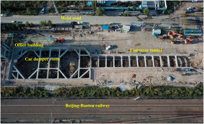
FIGURE 1. Surrounding environment of the foundation pit.
The north-side retaining structure of the excavation foundation pit is adjacent to Weisi Road, and the south-side retaining structure is adjacent to the Beijing–Baotou railway. The excavation sideline is approximately 16–18.18 m from the mainline of the Beijing–Baotou heavy-duty freight railway, approximately 40 m away from the mainline of the Beijing–Baotou passenger dedicated line and approximately 19.3 m from Weisi Road. The Beijing–Baotou heavy-duty freight railway, the main railway line to the northwestern region of China, is a Class I double-track electrified railway, and its designed speed can reach 160 km/h. On the other hand, the Beijing–Baotou passenger dedicated line has a higher designed speed of 200 km/h in the Hohhot–Baotou section.
The west-side retaining structure of the foundation pit close to an office building under construction is approximately 2.5 m from the excavation edge, with a cast-in-place pile foundation. The east side is an open space. The railway subgrade is approximately 2.0 m higher than that of the excavation surface. Table 1 provides the detailed physical/mechanical parameters of the soil layers.
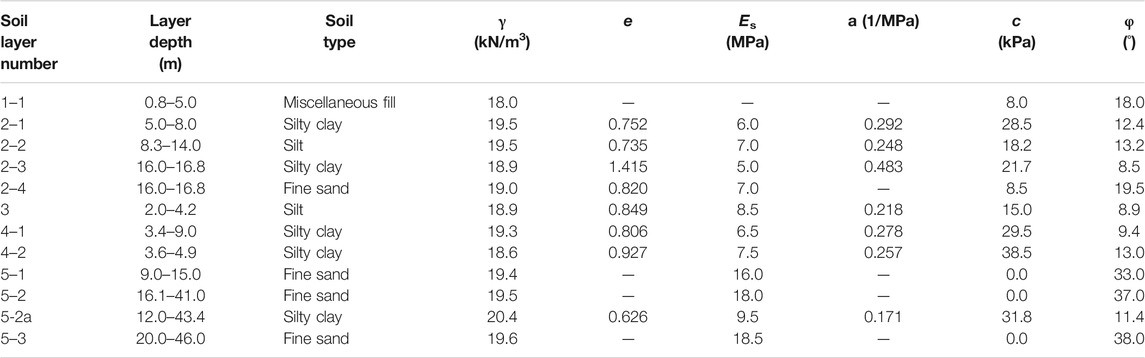
TABLE 1. Physical and mechanical characteristics of the soil layers.
The burial depth of the groundwater level is approximately 2.6–4.6 m, mainly in the fine sand layer of the unit (layer 5-1). The groundwater table is recharged by atmospheric precipitation and the Yellow River and has a close hydraulic connection with the Yellow River 1.5 km away. The permeability coefficient is 7.2 m/d, and the radius of influence is 90 m.
Design of Retaining and Protection Structure
The surrounding environment and construction condition of the deep foundation pit is relatively severe from an engineering point of view (Figure 1). For this, the deformation values of the retaining structure and the settlement values of the railway subgrade with 18 m is required to strictly control within the design range. The safety control target of the foundation pit includes the deformation limit of the adopted retaining structure (Huang et al., 2020a; Huang et al., 2021), ground surface settlement, subgrade settlement, track smoothness, groundwater seepage (Zhang et al., 2016; Huier and Shoude, 2020; Bai et al., 2021b), foundation pit or side slope safety (Yang and Bai, 2019; Huang et al., 2020b; Bian et al., 2021), etc.
Difficulties and Countermeasures
In view of the engineering geological conditions and the foundation pit feature, as well as the surrounding environment (Figure 1), the key problem to the success/failure of the foundation pit design is to control the subgrade deformation/settlement of the adjacent Beijing–Baotou railway. To strictly restrict the deformation and settlement of the adjacent railway, it is of importance to control the change of groundwater due to the excavation of the foundation pit, as well as the deformation values of the retaining structure.
The groundwater level of the site is shallow from the Earth’s surface. The stratum within the excavation extent of the foundation pit is mainly a five-unit fine sand layer in depth, which has a relatively large permeability coefficient and radius of influence of dewatering. If the groundwater table is reduced from 2.6 to 19.0 m (0.5 m below the deepest foundation base) by dewatering, additional settlement will occur on the railway subgrade adjacent to the foundation pit due to the increase in effective stress in the stratum. The settlement of the subgrade will be approximately 78 mm. Sand streaking and leakage on each side of the installed retaining structure as well as the pit bottom will increase the deformation and even endanger the safety of the installed retaining structure. Therefore, the groundwater control of foundation pits is the key problem to the success/failure of foundation pit design projects.
After comprehensive consideration, groundwater control adopts the scheme of a surrounding vertical water resistance barrier plus full reinforcement at the pit bottom (forming a five-sided water-stop structure) and a small number of pressure relief wells in the pit. The water resistance barrier formed by 30-m long three-axis mixed piles is constructed near the excavated foundation pit, and the pile end enters the 5-2a silty clay layer as a relatively waterproof layer. A reinforced water resistance barrier of double-row three-axis mixing piles is set near the railway side to reduce the possibility of leakage from the sidewall of the foundation pit close to the railway. Because the thickness of the 5-2a layer of silty clay varies within the excavation area and is missing in some sections, the foundation base is fully reinforced with 5 m thick triaxial mixing piles, which form a five-sided water-stop the structure with the water resistance barrier on the side of the pit. The water resistance barrier extends the groundwater seepage path, thereby controlling the groundwater drawdown within the railway area and the settlement of the subgrade caused by precipitation. A kind of high pressure jet grouting technology is utilized to solidify the soil layer between the soldier piles, controlling the settlement of the soil layer between all the piles, and strengthen the blockage of groundwater at the sidewalls of the foundation pit. There are seven pressure relief wells in the pit, and the well depth is controlled at 2 m approximately above the top interface of layer 5-2a. The pressure relief reduces the pressure of the groundwater in the enclosed space formed between the bottom and the side water resistance barrier and the 5-2a silty clay, which effectively controls the heave of the pit bottom and reduces the impact of dewatering in the pit on the side subgrade.
The deformation and settlement of the retaining structure as well as the heave of the pit bottom are the key points of the deep deformation safety control of the foundation pit. Excessive deformation or settlement will aggravate the settlement of adjacent railway subgrades (Figure 2). To effectively restrict the deformation or settlement of the retaining structure, a comprehensive retaining and protection system of a soldier pile wall plus three-layer cross-lot bracing with reinforced concrete plus water resistance barrier plus foundation reinforcement is comprehensively adopted at the soil layers of the deep foundation pit bottom. For the design of the foundation pit, the importance level of pit excavation is taken as class I, the railway load is taken as 80 kPa, and the highway load is taken as 25 kPa. The pile diameter of the car dumper room section is set to 1.2 m, the pile spacing is set to 1.5 m, and the pile length is set to 31 m. According to the different excavation depths of the conveyor tunnel section, the pile diameters are 0.9, 1, and 1.2 m, corresponding to the pile spacing 1.2, 1.3, 1.5 m, and the pile length is in the range of 12–27 m. A layer of shotcrete reinforced with wire mesh is used between the piles. The columns are set up in the middle of the internal bracing, the lower part of the column adopts bored piles, and the upper part adopts a steel-spaced column. To limit the lateral displacement (i.e., horizontal direction) of the retaining structure and control the heave of the pit bottom, the passive side of the soil layer at the bottom location of the foundation pit is reinforced with Φ850@600 mm × 5.0 m three-axis mixing piles. In accordance to simulation calculation, the heave of the pit bottom after reinforcement is reduced from 61.2 mm to less than 20 mm. This result can meet the limited requirements for safety.
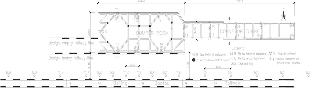
FIGURE 2. Arrangement of the monitoring points around the car dumper room (size unit: mm).
Influence of Foundation Pit Excavation on Railway Subgrade
To determine the possible damage during foundation pit excavation on the operational safety of the Beijing–Baotou freight railway and Beijing–Baotou passenger dedicated line, LIZHENG deep foundation pit design software, and MIDAS GTS (a geotechnical analysis software) were utilized to discuss the deformation of the subgrade.
The shortest distances between the excavation sideline of the car dumper room and the conveyor tunnel foundation pit from the mainline of the Beijing–Baotou railway are 18.18 and 26.18 m, respectively. Besides, the excavation depth of the conveyor tunnel has gradually reduced, and the impact factors of the excavation on the environment have also gradually decreased. The ground settlement from the excavation sideline to the mainline of the Beijing–Baotou railway is shown in Figure 3. For comparison, these results are calculated by the LIZHENG software through the so-called triangle method, the proponent method, as well as the parabola method. The three assumptions give different forms of surface settlement (i.e., triangular, exponential and parabolic distributions). As a result, the settlement at 18.18 m near the foundation pit excavation sideline (i.e., the mainline of the Beijing–Baotou freight railway) is less than 6 mm according to the three calculation methods, which satisfies the control requirements of safety assessment in Table 2.
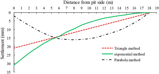
FIGURE 3. Ground settlement distributions away from pit side.
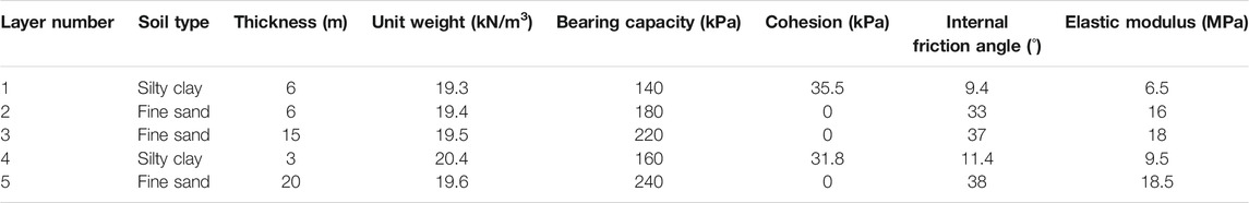
TABLE 2. Soil parameters used in the numerical calculation.
For a numerical calculation, the length, the width, and the height of the model are taken as 200 × 60 × 50 m (Figure 4). In the calculation, the soil layers are considered horizontally distributed, and the same soil layer is isotropic. The bottom surface is set to be restricted in every direction. The top ground surface is set to a free surface without restriction. The four sides have only normal constraints, and the other directions are free and unconstrained. HS-small strain constitutive model is adopted for the soil. The soil layers below the groundwater level are calculated according to the effective shear strength parameters. Table 2 provides the soil parameters used in the calculation.
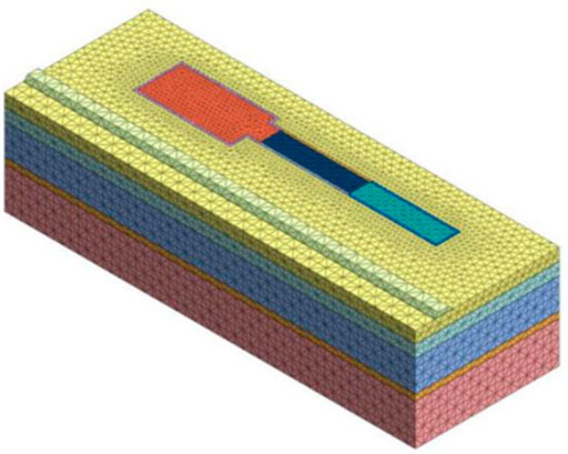
FIGURE 4. Numerical model and calculation mesh.
During the simulation, the calculation is carried out according to the steps of original stress balance: construction of soldier piles and first layer of internal bracing, excavation of first layer, construction of second layer of internal bracing (i.e., excavation to 6 m), excavation of second layer, construction of third layer of internal bracing (i.e., excavation to 12 m), and excavation of third layer (i.e., excavation to foundation pit bottom). Thus, the vertical settlement and the additional horizontal deformation of the subgrade at each stage of the construction are shown in Figures 5, 6, and the locations of points 1, 2, 3, 4, and 5 are indicated in Figure 2.
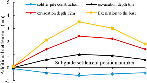
FIGURE 5. Cumulative settlement of the subgrade.
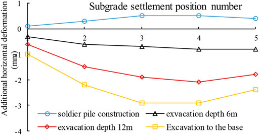
FIGURE 6. Cumulative lateral horizontal deformation of the subgrade.
Figure 5 makes it clear that the additional vertical deformation of the Beijing–Baotou railway owing to the construction of soldier piles, the excavation of the first soil layer, then the excavation of the second soil layer, and the excavation of the third soil layer is −0.6 to 3.5 mm, which meets the limit value of 6 mm under the static regular maintenance conditions. Figure 5 also indicates that the vertical deformation of the railway subgrade gradually increases with increasing excavation depth, and the subgrade deformation corresponding to the center part of the foundation pit is actually the largest and gradually decreases to both sides. The deformation at point 1 of the subgrade corresponding to 20 m outside the excavation sideline on the west side of the dumper room is approximately zero, while the settlement at point 5 on the east side owing to the narrowing of the excavation surface of the conveyor tunnel foundation pit is also rapidly reduced.
Figure 6 indicates that the additional horizontal deformation (vertical to the long-side) of the Beijing–Baotou railway caused by construction is −2.9–0.5 mm, which meets the limit value of 6 mm under the conditions of regular maintenance. In the meantime, the deeper the excavation depth of the foundation pit is, the larger the lateral deformation (i.e., horizontal direction) of the subgrade. The lateral deformation of the subgrade corresponding to the center of the dumper room is the largest and gradually decreases.
Field Measurement Analysis
Arrangement of the Deformation Monitoring Points
Figure 2 also gives the locations of the field monitoring points. During the pit excavation, the following items are measured: the horizontal displacement and vertical settlement of the pile top, the axial force of the cross-lot struts, the horizontal deformation of lower part, the settlement of the column piles, and the settlement of the railway subgrade.
The Beijing–Baotou railway line is a low subgrade section within the construction range, and the difference in height between the subgrade and the ground is approximately 2.0 m. To avoid affecting the traffic safety of the existing lines, the subgrade settlement monitoring points are arranged close to the outside of the railway protective net, approximately 4.0 m away from the railway mainline, and a monitoring point is arranged every 9–18 m in the excavation-affected section. The displacement of the lower part of the soldier pile wall is measured by an inclinometer, the settlement of the soldier pile top is measured by leveling.
Deformation of Retaining Structure
Figure 7 indicates the evolution process of the horizontal displacement of the pile top over time on the north and south sides of the car dumper room. The locations of the testing site can be seen in Figure 2. With increasing the excavation depth, the horizontal displacement of the pile top increases. However, its horizontal displacement increases rapidly during the excavation of the second soil layer (case 3), while the increase in the displacement of the pile top is relatively slow when the third layer is excavated (case 4). The displacement of the pile top roughly remains steady after digging to the foundation pit bottom. The displacement of the pile tends to decrease after the second layer of cross-lot bracing is removed (case 7). When the third soil layer was excavated, the horizontal displacement of point ZS01 into the pit was significantly reduced due to water leakage and sand streak at the corresponding position during excavation, which induces the reduction of wall back resistance and the displacement of the soldier piles to the outside of the pit. Actually after the leakage is solved, the horizontal displacement at the top of the pile returns to the normal state.
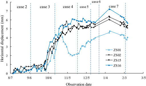
FIGURE 7. Horizontal deformation of soldier pile top.
On the same vertical railway profile, the displacement near the railway side is much greater than the displacement far away from the railway side (ZS01 corresponds to ZS16, ZS02 corresponds to ZS15), and the maximum displacement at the top of the pile in the horizontal direction is approximately 7.6 mm. Due to the large rigidity of the three cross-lot struts in the middle part of the foundation pit, the difference in displacement between the north and south sides (ZS02, ZS15) of the middle of the foundation pit is very small (approximately 0.3 mm). The displacement difference between the two sides of the foundation pit with only the knee bracing is relatively large (i.e., 2.87 mm).
Figure 8 shows the settlement comparison of the pile tops on the north side and south side of the car dumper room (herein, the negative value is settlement; the positive value is heave). In the process of the foundation pit excavation (cases 2, 3, 4), the pile top deformation was dominated by settlement, and with increasing the depth of excavation, the pile top settlement gradually increased, and the maximum settlement was approximately 5 mm. With the accomplishment of the foundation bottom (case 5), the settlement of the pile top has gradually decreased. After the third layer of cross-lot bracing is removed (case 6), the vertical deformation of the pile top is transformed into heave. At this time, the maximum heave is approximately 5 mm. Besides, the settlement of the pile top close to the railway (i.e., the south side of the foundation pit) is apparently smaller than the settlement of the pile top of the side far from the railway, which is exactly the opposite of the change in the lateral displacement.

FIGURE 8. Vertical deformation of soldier pile top.
Figure 9 shows the comparison of the retaining structure deformation on the north and south sides of the car dumper room (positive value is displacement inward and negative value is displacement outward). The locations of the testing site can be seen in Figure 2. Figure 9 also indicates that the deformation of the retaining structure is generally small at both ends and large at the middle part, and the deformation measured near the railway is larger than the deformation measured far away from the railway. With increasing the excavation depth, the deformation increases, gradually. In this way, the deformation of the retaining structure is smaller when the first layer and second layer of soil are excavated, but its deformation increases significantly when the third soil layer is excavated. As a result, the maximum deformation of the railway side retaining structure is only 6.3–7.1 mm, and the displacement away from the railway side is 4.5–5.5 mm.
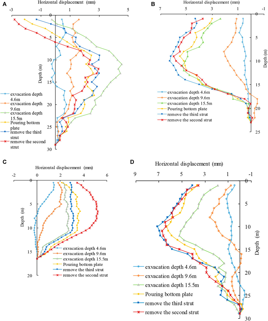
FIGURE 9. Horizontal deformation of retaining structure: (A) SS02, (B) SS15, (C) SS01, and (D) SS16.
Three cross-lot struts are installed in the central part of the foundation pit of the car dumper. When the excavation depth is small, the bias pressure effect of the railway on the foundation pit is not obvious. However, after the excavation to the base, the retaining structure shows similar deformation characteristics (at the SS2 and SS15 monitoring points) as the results of Shi and Yang (2011): as the excavation progresses, the upper part of the retaining structure located at the side away from the railway is deformed out of the pit, while the middle and lower sections are deformed into the pit. However, the deformation characteristics of railway bias pressure are not shown in the part where only knee bracing is set in the foundation pit (at the section of monitoring points SS1 and SS16).
Subgrade Settlement Analysis
Figure 10 shows the variation in subgrade settlement with time, which shows that the settlement of the subgrade on the side of the excavated foundation pit gradually increases when the excavation depth gradually increases. The settlement rate and settlement amount during the excavation stage (cases 2, 3, 4) are relatively small. When the excavation process is completed, the settlement amount of the monitoring points near the dumper room is approximately 2.1–3.7 mm. However, the settlement rate and amount of subgrade in the stage of cross-lot bracing removal (cases 6 and 7) are relatively large. After the third cross-lot bracing replacement, the settlement of the corresponding monitoring points is 3.7–7.0 mm. The excavation depth remains at 7.5 m after the backfill outside the structure of the car dumper room, and the settlement is basically stable at 3.9–7.1 mm on each side of the excavated foundation pit.
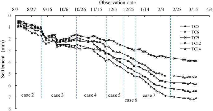
FIGURE 10. Subgrade settlement variation with time.
Figure 10 expresses the settlement changes of the vertical section of the subgrade at different construction stages. This result indicates that the settlement of each point on the longitudinal section of the entire subgrade is almost the same. The settlement of the monitoring point of the subgrade, after excavation to the base, is less than 3.7 mm; however, after the internal bracing is removed, the subgrade settlement of the corresponding part of the foundation pit has increased significantly, forming two settlement troughs. That is, the two ends are smaller and the middle is larger. Moreover, their settlements are bounded by the center of the car dumper room. This phenomenon reflects that the deformation influence dies to foundation pit excavation on the subgrade settlement in the cross-lot bracing removal stage is greater than the influence of the deformation on the settlement of the subgrade in the excavation stage.
The positions of subgrade settlements of points 1, 2, 3, 4, and 5 (Figure 2) are extracted by numerical simulation, which basically correspond to the positions of subgrade settlement monitoring points TC14, TC12, TC9, TC6, and TC5 (Figure 2). In the simulation, the settlements of points 1, 2, 3, 4, and 5 after excavation to the basement are 0.1, 2.1, 3.5, 3.0, and 1.8 mm, respectively, while the measured settlements of the corresponding positions are 3.0, 2.5, 2.1, 3.1, and 3.7 mm. The maximum settlement is basically the same, but the location of the maximum settlement is different.
Figure 11 also shows the results at the TC15 and TC16 (Figure 2) monitoring points, which are more than 40 m away from the west side of the foundation pit. In fact, the settlement of the subgrade after the removal of the second layer or cross-lot bracing is greater than 3 mm, showing that the impact of foundation pit excavation on the subgrade settlement is almost three times the excavation depth. Overall, the measured results of the vertical settlement of the subgrade (Figure 11) are slightly larger than the previous calculation results (Figure 5), but the maximum value is about 4–7 mm which meets the needs of the engineering calculation.

FIGURE 11. Subgrade settlement changes in longitudinal section.
Discussion
For deep foundation pit with settlement-sensitive structures, such as railway subgrade close to the foundation pit, the groundwater control scheme with a five-sided water-stop structure and appropriate pressure relief wells in the pit, it can not only effectively avoid the impact of great depth dewatering on the settlement of adjacent subgrades but also determine the deformation properties of the retaining structure and reduce the heave of the bottom of the pit. In this way, the influence of dewatering and retaining structure deformation on the settlement of sensitive structures is controlled.
The reinforcement at the foundation pit bottom effectively determines the horizontal displacement of the installed retaining structure, the heave of the hole bottom, and the leakage of groundwater at the pit bottom. However, when piles using deep cement mixing are applied to enhance the pit bottom soil, the upwelling of the cement slurry will cause a large amount of cement to be mixed in the soil above the pit bottom, resulting in a high strength of the pit core soil, which will cause greater difficulties to the subsequent excavation construction of the pit core soil. Therefore, the pit bottom reinforcement design should adopt the method of pilot hole plus high-pressure jet grouting piles and only spray the cement slurry below the pit bottom, which not only effectively utilizes the cement but also reduces the difficulty of excavating the pit core soil.
Since the net distance between the soldier piles is very small, some necessary measures should be taken to control the diameter and height of the soldier piles, otherwise, the construction will damage the reinforcement cages of adjacent piles and have harmful influences on the stress of the soldier pile. At the same time, the inclination and diameter expansion of the supporting piles will also affect the construction of the high-pressure jet grouting piles between the piles, which will damage the effect of the water-resistance barrier on the pit side.
Conclusion
For the deep foundation pit close to the existing railway lines, the five-sided water-stop structure formed by cement-soil piles around and at the bottom of the pit can effectively reduce the subgrade consolidation settlement caused by deep dewatering, and the water resistance barrier at the bottom of the pit can be effective in reducing the lateral displacement (i.e., in the horizontal direction) of the installed retaining structure and the upward heave of the pit bottom.
For retaining structures, the lateral displacement near the railway sides is obviously larger than the lateral displacement on the other side due to the bias pressure of the subgrade on the pit side. The cross-lot struts across the foundation pit will transfer the bias pressure of the subgrade to the retaining structure far away from the railway, while the transfer effect of the knee bracing is not obvious.
For the deep foundation pit adjacent to the existing railway lines, one should pay enough attention to the amount of subgrade deformation. Moreover, the deformation rate caused by the removal of internal bracing is significantly obvious than the deformation of the foundation pit on the settlement of the subgrade caused by the excavation.
Data Availability Statement
The raw data supporting the conclusion of this article will be made available by the authors, without undue reservation.
Author Contributions
GW mainly provided research methods in this paper, and the other authors WC, LC, YL, SL, JY, and BW contributed to the investigation and analysis.
Funding
This research was funded by the Hebei Province Postdoctoral Research Projects Merit-based Funding Program (B2020005008).
Conflict of Interest
Author YL, SL, JY, and BW were employed by the company Hebei Research Institute of Construction and Geotechnical Investigation. Author LC is employed by the company Xinfa Group Co Ltd.
The remaining authors declare that the research was conducted in the absence of any commercial or financial relationships that could be construed as a potential conflict of interest.
Publisher’s Note
All claims expressed in this article are solely those of the authors and do not necessarily represent those of their affiliated organizations, or those of the publisher, the editors and the reviewers. Any product that may be evaluated in this article, or claim that may be made by its manufacturer, is not guaranteed or endorsed by the publisher.
References
Bai, B. (2006). Fluctuation Responses of Saturated Porous media Subjected to Cyclic thermal Loading. Comput. Geotechnics 33 (8), 396–403. doi:10.1016/j.compgeo.2006.08.005
Bai, B., Guo, L., and Han, S. (2014). Pore Pressure and Consolidation of Saturated Silty clay Induced by Progressively Heating/cooling. Mech. Mater. 75, 84–94. doi:10.1016/j.mechmat.2014.04.005
Bai, B., Jiang, S., Liu, L., Li, X., and Wu, H. (2021). The Transport of Silica Powders and lead Ions under Unsteady Flow and Variable Injection Concentrations. Powder Tech. 387, 22–30. doi:10.1016/j.powtec.2021.04.014
Bai, B., Long, F., Rao, D., and Xu, T. (2017). The Effect of Temperature on the Seepage Transport of Suspended Particles in a Porous Medium. Hydrol. Process. 31 (2), 382–393. doi:10.1002/hyp.11034
Bai, B., Rao, D., Chang, T., and Guo, Z. (2019). A Nonlinear Attachment-Detachment Model with Adsorption Hysteresis for Suspension-Colloidal Transport in Porous media. J. Hydrol. 578, 124080. doi:10.1016/j.jhydrol.2019.124080
Bai, B., Rao, D., Xu, T., and Chen, P. (2018). SPH-FDM Boundary for the Analysis of thermal Process in Homogeneous media with a Discontinuous Interface. Int. J. Heat Mass Transfer 117, 517–526. doi:10.1016/j.ijheatmasstransfer.2017.10.004
Bai, B., and Shi, X. (2017). Experimental Study on the Consolidation of Saturated Silty clay Subjected to Cyclic thermal Loading. Geomech. Eng. 12 (4), 707–721. doi:10.12989/gae.2017.12.4.707
Bai, B., and Su, Z. (2012). Thermal Responses of Saturated Silty clay during Repeated Heating-Cooling Processes. Transp Porous Med. 93 (1), 1–11. doi:10.1007/s11242-012-9939-6
Bai, B. (2013). Thermal Response of Saturated Porous Spherical Body Containing a Cavity under Several Boundary Conditions. J. Therm. Stresses 36 (11), 1217–1232. doi:10.1080/01495739.2013.788389
Bai, B., Xu, T., Nie, Q., and Li, P. (2020). Temperature-driven Migration of Heavy Metal Pb2+ along with Moisture Movement in Unsaturated Soils. Int. J. Heat Mass Transfer 153, 119573. doi:10.1016/j.ijheatmasstransfer.2020.119573
Bai, B., Yang, G.-c., Li, T., and Yang, G.-s. (2019). A Thermodynamic Constitutive Model with Temperature Effect Based on Particle Rearrangement for Geomaterials. Mech. Mater. 139, 103180. doi:10.1016/j.mechmat.2019.103180
Bai, B., Zhou, R., Cai, G., Hu, W., and Yang, G. (2021). Coupled Thermo-Hydro-Mechanical Mechanism in View of the Soil Particle Rearrangement of Granular Thermodynamics. Comput. Geotechnics 137 (8), 104272. doi:10.1016/j.compgeo.2021.104272
Bian, X., Hu, H., Zhao, C., Ye, J., and Chen, Y. (2021). Protective Effect of Partition Excavations of a Large-Deep Foundation Pit on Adjacent Tunnels in Soft Soils: a Case Study. Bull. Eng. Geol. Environ. 80, 5693–5707. doi:10.1007/s10064-021-02256-9
Fang, H., Fang, L., and Tong, L. (2017). Analysis on Influencing Factors of Foundation Pit Excavation on Deformation of High-Speed Railway Subgrade. Railway Stand. Des. 61 (6), 125–130. doi:10.13238/j.issn.1004-2954.2017.06.026
Gao, X. (2018). Study on the Influence of Deep Foundation Pit Construction on Nearby High-Speed Railway Sub Grade. High Speed Railway Tech. 9 (3), 31–35.
Guo, P., Gong, X., and Wang, Y. (2019). Displacement and Force Analyses of Braced Structure of Deep Excavation Considering Unsymmetrical Surcharge Effect. Comput. Geotechnics 113, 103102. doi:10.1016/j.compgeo.2019.103102
Houston, S. L. (2019). It Is Time to Use Unsaturated Soil Mechanics in Routine Geotechnical Engineering Practice. J. Geotech. Geoenviron. Eng. 145 (5), 02519001. doi:10.1061/(asce)gt.1943-5606.0002044
Huang, F., Cao, Z., Jiang, S.-H., Zhou, C., Huang, J., and Guo, Z. (2020). Landslide Susceptibility Prediction Based on a Semi-supervised Multiple-Layer Perceptron Model. Landslides 17, 2919–2930. doi:10.1007/s10346-020-01473-9
Huang, F., Ye, Z., Jiang, S.-H., Huang, J., Chang, Z., and Chen, J. (2021). Uncertainty Study of Landslide Susceptibility Prediction Considering the Different Attribute Interval Numbers of Environmental Factors and Different Data-Based Models. Catena 202, 105250. doi:10.1016/j.catena.2021.105250
Huang, F., Zhang, M., Wang, F., Ling, T., and Yang, X. (2020). The Failure Mechanism of Surrounding Rock Around an Existing Shield Tunnel Induced by an Adjacent Excavation. Comput. Geotechnics 117, 103236. doi:10.1016/j.compgeo.2019.103236
Huier, X., and Shoude, L. (2020). Safety Analysis of Deep Foundation Excavation in Water-Rich Soft Soils Based on BIM. Math. Probl. Eng. 2020, 4923984. doi:10.1155/2020/4923984
Huo, J., Gong, Q., and Chen, J. (2011). Analysis of the Deformation of Retaining Structure of Pit-In-Pit Excavation. J. Civil Architectural Environ. Eng. 33 (S1), 139–142.
Huo, J., and Zhou, S. (2014). Discrimination Method of Pit-In-Pit Excavation Critical Spacing Based on Unit Shear Plane. Urban Rapid Rail Transit. 27 (5), 80–85.
Li, M., Chen, J., Xu, A., Dong, F., and Wang, J. (2015). Interactive Behavior between the Deep Excavation and Close Operating Railway. Chin. J. Underground Space Eng. 11 (2), 435–439.
Li, M., Xiao, J., and Gong, Q. (2011). Dynamic Analysis of the Interaction between the Existed Line and the Foundation System during Excavation. J. East China Jiaotong Univ. 28 (5), 93–97. doi:10.1016/j.nucengdes.2010.04.023
Li, X., Liu, X., Li, C. Z., Hu, Z., Shen, G. Q., and Huang, Z. (2019). Foundation Pit Displacement Monitoring and Prediction Using Least Squares Support Vector Machines Based on Multi-point Measurement. Struct. Health Monit. 18 (3), 715–724. doi:10.1177/1475921718767935
Li, Z., Han, M., Liu, L., Li, Y., and Yan, S. (2020). Corner and Partition wall Effects on the Settlement of a Historical Building Near a Supported Subway Excavation in Soft Soil. Comput. Geotechnics 128, 103805. doi:10.1016/j.compgeo.2020.103805
Lin, G., Xu, C., and Cai, Y. (2010). Research on Characters of Retaining Structures for Deep Foundation Pit Excavation under Unbalanced Heaped Load. Rock Soil Mech. 31 (8), 2592–2598. doi:10.16285/j.rsm.2010.08.031
Luo, K., and Lei, X. (2010). The Dynamic Analysis of the Existing Railway’s Subgrade Settlement Caused by Excavation Piton Hu-Ning Line. J. Railway Eng. Soc. 1 (9), 5–8.
Nogueira, C. d. L., Azevedo, R. F. d., and Zornberg, J. G. (2011). Validation of Coupled Simulation of Excavations in Saturated clay: Camboinhas Case History. Int. J. Geomech. 11 (3), 202–210. doi:10.1061/(asce)gm.1943-5622.0000077
Pathirana, S., Rodrigo, A., and Halwatura, R. (2019). Effect of Building Shape, Orientation, Window to wall Ratios and Zones on Energy Efficiency and thermal comfort of Naturally Ventilated Houses in Tropical Climate. Int. J. Energ. Environ Eng 10, 107–120. doi:10.1007/s40095-018-0295-3
Rashidi, F., and Shahir, H. (2019). Numerical Investigation of Anchored Soldier Pile wall Performance in the Presence of Surcharge. Int. J. Geotechnical Eng. 13 (2), 1–10. doi:10.1080/19386362.2017.1329258
Seong, J. H., Jung, S. H., and Shin, J. Y. (2011). A Study for Safety Management on Ground Excavation by Analysis of Accident Events. J. Korea Inst. Struct. Maintenance Inspection 15 (6), 175–183. doi:10.11112/jksmi.2011.15.6.175
Shen, Y., Wang, H., and Jing, P. (2014). Orthogonal Analysis of Influence Factors for Foundation Pit Support Approaching Existing Railway Line. J. Traffic Transportation Eng. 14 (2), 14–20.
Shi, Y., and Yang, J. (2011). Analysis of Field Testing for Deformation and Internal Force of Unsymmetrical Loaded Foundation Pit’s Enclosure Structure Close to Railway. Chin. J. Rock Mech. Eng. 30 (4), 826–833.
Szepesházi, A., Mahler, A., Mahler, A., and Móczár, B. (2016). Three Dimensional Finite Element Analysis of Deep Excavations' Concave Corners. Period. Polytech. Civil Eng. 60 (3), 371–378. doi:10.3311/ppci.8608
Wang, H.-L., Chen, R.-P., Qi, S., Cheng, W., and Cui, Y.-J. (2018). Long-term Performance of Pile-Supported Ballastless Track-Bed at Various Water Levels. J. Geotech. Geoenviron. Eng. 144, 04018035. doi:10.1061/(asce)gt.1943-5606.0001890
Wang, H.-L., Cui, Y.-J., Lamas-Lopez, F., Dupla, J.-C., Canou, J., Calon, N., et al. (2018). Permanent Deformation of Track-Bed Materials at Various Inclusion Contents under Large Number of Loading Cycles. J. Geotech. Geoenviron. Eng. 144, 04018044. doi:10.1061/(asce)gt.1943-5606.0001911
Wang, L., Pang, J., and Xu, Y. (2016). Influence of Foundation Pit Excavation on Adjacent Metro Tunnels. Rock Soil Mech. 37 (7), 2004–2010. doi:10.16285/j.rsm.2016.07.022
Xu, C., Cheng, S., and Cai, Y. (2014). Deformation Characteristic Analysis of Foundation Pit under a Symmetric Excavation Condition. Rock Soil Mech. 35 (7), 1929–1934. doi:10.2307/1571996
Xu, C., Xu, Y., and Sun, H. (2013). Characteristics of Braced Excavation under a Symmetrical Loads. Math. Probl. Eng. 2013 (11), 389–405. doi:10.1155/2013/452534
Yang, G., and Bai, B. (2019). Thermo-hydro-mechanical Model for Unsaturated clay Soils Based on Granular Solid Hydrodynamics Theory. Int. J. Geomech. 19 (10), 04019115. doi:10.1061/(asce)gm.1943-5622.0001498
Ying, H., Li, T., Yang, Y., and Xie, X. (2011). Effect and Application of Partition walls in Protecting Adjacent Buildings from Deep Foundation Pits. Chin. J. Geotechnical Eng. 33 (7), 1123–1128. doi:10.1631/jzus.B1000185
Zhang, P., Bai, B., Jiang, S., Wang, P., and Li, H. (2016). Transport and Deposition of Suspended Particles in Saturated Porous media: Effect of Hydrodynamic Forces and Pore Structure. Water Sci. Technol. Water Supply 16 (4), 951–960. doi:10.2166/ws.2016.011
Zhang, X., Shi, Y., and Zhang, Z. (2012). Dynamic Response of Enclosure Structure of an Unsymmetrical Loaded Foundation Pit Undertrain Induced Dynamic Load. J. Vibration Shock 31 (20), 103–109. doi:10.13465/j.cnki.jvs.2012.20.022
Zhang, X., Yang, J., Zhang, Y., and Gao, Y. (2018). Cause Investigation of Damages in Existing Building Adjacent to Foundation Pit in Construction. Eng. Fail. Anal. 83, 117–124. doi:10.1016/j.engfailanal.2017.09.016
Keywords: railway subgrade, numerical analysis, deformation, retaining structure, foundation pit
Citation: Wang G, Chen W, Cao L, Li Y, Liu S, Yu J and Wang B (2021) Retaining Technology for Deep Foundation Pit Excavation Adjacent to High-Speed Railways Based on Deformation Control. Front. Earth Sci. 9:735315. doi: 10.3389/feart.2021.735315
Received: 02 July 2021; Accepted: 21 September 2021;
Published: 05 November 2021.
Edited by:
Faming Huang, Nanchang University, ChinaReviewed by:
Pengfei Li, Beijing University of Technology, ChinaHan-Lin Wang, Hong Kong Polytechnic University, Hong Kong, SAR China
Copyright © 2021 Wang, Chen, Cao, Li, Liu, Yu and Wang. This is an open-access article distributed under the terms of the Creative Commons Attribution License (CC BY). The use, distribution or reproduction in other forums is permitted, provided the original author(s) and the copyright owner(s) are credited and that the original publication in this journal is cited, in accordance with accepted academic practice. No use, distribution or reproduction is permitted which does not comply with these terms.
*Correspondence: Guohui Wang, ghwang@bjtu.edu.cn