Numerical Simulation of Long-Term Deterioration of Rock Mass Supported by Shotcrete Lining
 Chao Kong1,2
  Kai Zhao
- 1School of Civil Engineering and Architecture, Southwest University of Science and Technology, Mianyang, China
- 2Shock and Vibration of Engineering Materials and Structures Key Laboratory of Sichuan Province, Mianyang, China
- 3College of Transportation Engineering, Nanjing Tech University, Nanjing, China
- 4State Key Laboratory of Mechanical Behavior and System Safety of Traffic Engineering Structures, Shijiazhuang, China
- 5School of Civil Engineering, Shijiazhuang Tiedao University, Shijiazhuang, China
The deterioration of rock mass and shotcrete lining has major consequences on the long-term performance of tunnels in the weak rock mass. In this study, the long-term behavior of rock mass and shotcrete in tunnels was simulated by using the three-dimensional finite difference method, considering the nonlinear deterioration mechanism. The degradation of rock mass was simulated by weakening the mechanical parameters, while the deterioration of shotcrete was modeled by decreasing the thickness. The support pressure, internal force, and displacement of the secondary lining were monitored with the gradual degradation of rock mass and shotcrete. As a consequence, the factor of safety (FoS) evolution with time was discussed. The results indicated that 1) the deterioration of both rock mass and shotcrete would significantly increase the rock pressure on the secondary lining, leading to an increase in the displacement (0–14 mm). The FoS of the secondary lining was reduced by 85%. 2) The influence of shotcrete’s deterioration on the secondary lining was relatively less, and the rock pressure on the secondary lining increased from 0 kPa to 13.8 kPa. The long-term safety of the tunnel is remarkably affected by the deterioration of rock mass, depending on the deterioration characteristics of the rock mass. Therefore, the deterioration characteristics of rock mass should be fully considered in tunnel maintenance.
1 Introduction
In most countries, the life span of a tunnel is generally expected to be 100 years or even more. Many unfavorable factors would decrease its serviceability and safety during tunnel operations, among which the time-dependent deterioration of rock mass and the lining is a key one (Yoshida et al., 1997; Sandrone and Labiouse, 2010; Tating et al., 2013; Mert, 2014). The time-dependent deterioration of rock mass has a great influence on the physical and mechanical parameters of rock mass, which can break the balanced state of the tunnel and produce additional load on the lining in the long term (Usman and Galler, 2013; Aghchai et al., 2020).
Under the influence of external factors, the weathering of rock mass results in a decrease in particle size, change in mineral composition, and decrease in cohesional strength (Lyu et al., 2020). The mechanisms of damage degradation of different rocks under water–rock interaction, wet and dry cycling, or considering the action of corrosive ions were studied (Gullà et al., 2006; Wong et al., 2016; Momeni et al., 2017; Liu et al., 2018; Castellanza et al., 2018). The deterioration of rock mass is a time-dependent phenomenon, which may lead to a reduction of the mechanical parameters due to weathering (Ladanyi, 1980; Graham and Au, 1985; Chandler and Apted, 1988; Khanlari et al., 2012; Undul and Tugrul, 2012), aging (Panet, 1979; Boidy et al., 2002) and some other factors. Extensive studies have been carried out on the deterioration mechanisms of rock mass. Tertiary mudstone tends to soften due to water absorption upon unloading, moisture/humidity changes, weathering, and deterioration with time (Yoshida et al., 1997); viscoplastic properties of the rock mass and shotcrete have been studied using the finite element method (Swoboda et al., 1987). Pore water pressure redistribution (Garber, 2003) and other special geological disasters could contribute to the deterioration of rock mass.
Concrete is the structural material of tunnel support, and its long-term mechanical properties have been studied by many researchers in tunnel engineering. Some concrete deterioration models have been proposed by considering service conditions (Lei et al., 2013; Jiang and Niu, 2016; Alexander and Beushausen, 2019). The deterioration of steel bars has been studied (Ahmad, 2003; Sola et al., 2019). In order to simplify the simulation, reinforcement deterioration is neglected in the present study. The deterioration of the lining is mainly induced by weathering and corrosion in the underground environment. The lining generally consists of shotcrete and the secondary lining. As a temporary support structure, no measures are taken to improve the durability of shotcrete. Simultaneously, shotcrete is tightly attached to rock mass and exposed to underground water. Behind the secondary lining, there is no way to get the shotcrete repaired. As a permanent support structure, the durability of the secondary lining could be maintained during operation. Therefore, the deterioration of the secondary lining could be neglected, and the deterioration of the lining mainly depends on shotcrete.
This study intends to improve the understanding of the mechanisms of long-term deterioration of rock mass and lining and the influence of the deterioration on tunnel performance. The FLAC3D three-dimensional finite difference method was used in the study, complying with deterioration criteria of rock mass and lining, to simulate the long-term deterioration procedure of rock mass and shotcrete.
2 Deterioration Mechanisms of Rock Mass and Lining
The deterioration of rock mass is a time-dependent phenomenon, which could decrease its shear strength and expansion, and the decrement could be presented by moving down the failure envelop accompanied by a reduction in its nonlinearity at low stress levels. With the evolution of deterioration, the failure mechanisms of point A near the unsupported tunnel are shown in Figure 1. In the initial state, the stress circle of point A kept off the failure envelop at a long distance. With the advancement of deterioration, the envelop moves down gradually. The envelop crosses the stress circle eventually, and point A is in a state of failure. The pressure from the rock mass also increases gradually with the advancement of deterioration.
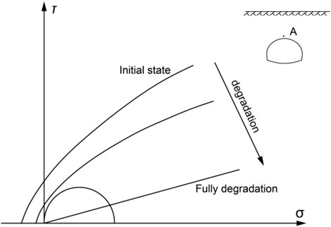
FIGURE 1. Stressed mechanisms under deterioration.
According to the various compositions of rock mass and the hydrogeological conditions around tunnels, the deterioration could be classified into the following three types:
1. Rock mass deteriorates quickly in a short time.
2. Rock mass deteriorates slowly over a long time.
3. Rock mass hardly deteriorates.
The main phases of the progressive transfer of the rock mass pressure from the primary support to the final lining system are described below. During excavation, the primary support (
The rock mass and lining deteriorated together according to different laws, and their deteriorations affect the long-term mechanical behavior of the tunnel. The deterioration mechanisms of the rock mass and lining are shown in Figure 2. The deterioration of both the rock mass and lining can significantly affect the serviceability and safety of tunnels during operation. The deterioration of rock mass will gradually increase the support pressure, and simultaneously, the deterioration of the lining will gradually decrease its own support capacity. When the lining is unable to support the rock mass, deformations such as crack and even collapse occurs resulting in the termination of tunnel operation time ahead of schedule.
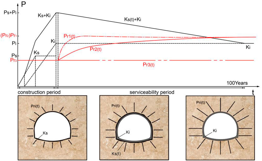
FIGURE 2. Deterioration mechanisms of the rock mass and lining.
3 Numerical Simulation
3.1 Numerical Model
In order to balance the model efficiency and accuracy, numerical models of different sizes were established, and the calculation results were analyzed and compared. The numerical model was determined as shown in Figure 3, with a dimension of 40 m in longitudinal length, 160 m in width, and 110 m in height. The tunnel is of a polycentric cross section and is 9.7 m in height, 50 m in width, and 50 m in buried depth. The thickness of the shotcrete and secondary lining is 20 and 35 cm, respectively. The model contains 294,400 elements and 613,848 nodes. In terms of boundary conditions, no vertical displacements were allowed along the base of the model, no lateral displacements were allowed along the vertical surface of the model, and the top surface of the model was allowed to be deformed freely.
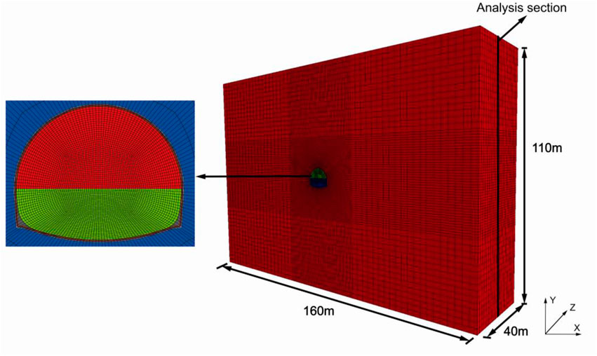
FIGURE 3. Tridimensional finite difference model.
The solid element is applied to simulate shotcrete, complying with the Mohr–Coulomb failure criterion that follows the elastic perfectly plastic stress–strain relationship (Usman and Galler, 2013), and a liner element is applied to simulate the secondary lining. The liner element is a build-in structural element in FLAC3D (as shown in Figure 4), which is usually applied to simulate the lining and geo-textile structure in geotechnical engineering. Liner structural elements are three-node, flat finite elements. In addition to providing the structural behavior of a shell, a shear-directed (in the tangent plane to the liner surface) frictional interaction occurs between the liner and the FLAC3D grid. In addition, in the normal direction, both compressive and tensile forces can be carried, and the liner may break free from (and subsequently come back into contact with) the grid (FLAC3D 2005). Interface elements can be used to model the effect of joints, faults, and frictional interfaces between bodies. Interfaces operating in a small-strain mode derive their forces from a comparison of “virtual positions” of the two interacting faces, where a “virtual position” of a point is the original coordinate of the point combined with the accumulated displacement to date. If one contacting object is removed (for example, backfill within a tunnel) and another substituted (for example, a liner is installed) using the same interface, then large initial stresses may appear because the two sides of the interface appear to interpenetrate (Zhao et al., 2022). The mechanical parameters of the shotcrete and secondary lining are shown in Tables 1, 2, respectively.
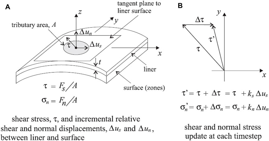
FIGURE 4. Idealization of interface behavior at a liner node. (A) Liner and surface. (B) Shear and normal stress (Itasca, 2005).

TABLE 1. Mechanical parameters of the shotcrete.
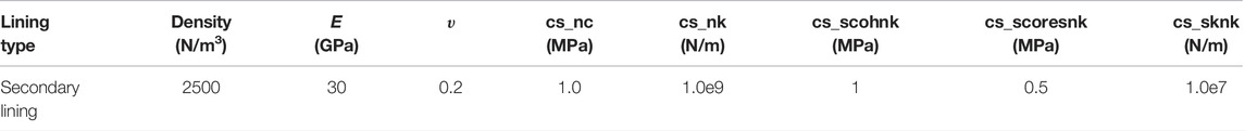
TABLE 2. Mechanical parameters of the secondary lining (FLAC3D 2005).
3.2 Simulation of the Deterioration of Rock Mass
According to abundant studies on various rock masses, the failure criterion was put forward by Yoshida et al. (1990), which could describe the time-dependent deterioration of rock mass.
where A, B, and S are the strength parameters. Strength during deterioration is represented by interpolating the strength parameters (A, B, and S) from the initial to the fully deteriorated values using the following inverse-hyperbolic function of time (Yoshida et al., 1990; Yoshida and Adachi, 2010).
where X is the strength parameter (A, B, and S); x is the strength reduction-rate parameter (a, b and c); t is time. The subscripts o and fs denote the initial and fully deteriorated values, respectively.
The deterioration of rock mass generally complies with Mohr–Coulomb and Hoek–Brown failure criteria that follow the elastic perfectly plastic stress–strain relationship or elastic perfectly plastic soften stress–strain (Sandrone and Labiouse, 2010; Sulem et al., 1987; Ladanyi,1974). In the numerical simulation of this study, a solid element is applied to simulate the rock mass, complying with Mohr–Coulomb failure criterion that follows the elastic perfectly plastic stress–strain relationship. Eq. 1 describes the Mohr–Coulomb criterion when B = 1, and at this time, parameters A and S influence the deterioration of rock mass, where
The mechanical properties of rock mass are indirectly determined (through RMR) from the Q system by means of commonly used empirical equations and correlations as described in the following equations. Initial Q is assumed to be 2 in the numerical simulation, and relative physical and mechanical parameters are computed and shown in Table 3.
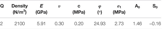
TABLE 3. Initial mechanical parameters of rock mass (before deterioration).
As summative and quantifiable formulas for the characteristic of the rock mass, RMR and Q systems are based on studies on considerable rock mass in the natural state, including rock mass in various conditions of deterioration. So, RMR and Q systems are considered applicable to rock mass during deterioration (Tugrul, 1998; Serafim and Pereira, 1983; Bieniawski, 1989; Palmstrom, 2000).
The deterioration of rock mass in the numerical simulation is classified into three types:
3.2.1 Case 1
It is assumed that the mechanical parameters of rock mass decreased to a quarter of its original value in 10 years due to its deterioration (
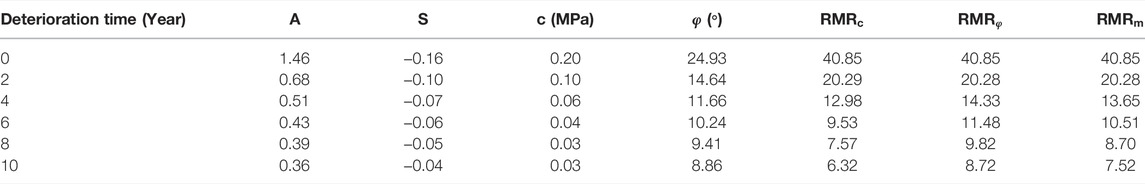
TABLE 4. Time-dependent parameters of rock mass during deterioration.
As shown in Table 4,
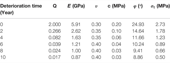
TABLE 5. Time-dependent mechanical parameters of rock mass during deterioration.
3.2.2 Case 2
It is assumed that the mechanical parameters of rock mass decreased to a quarter of its original value in 100 years due to its deterioration (
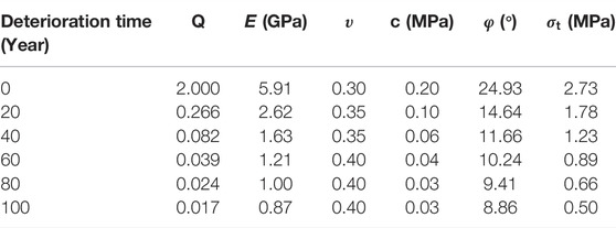
TABLE 6. Time-dependent mechanical parameters of rock mass during deterioration.
3.2.3 Case 3
It is assumed that rock mass rarely deteriorated in 100 years (
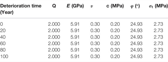
TABLE 7. Time-dependent mechanical parameters of rock mass during deterioration.
3.3 Simulating the Deterioration of the Lining
In the lining system, shotcrete alone deteriorated in the numerical simulation. According to Nguyen (2005), the thicknesses of the deterioration zone
Yokozeki et al. (2004) investigated the tunnels in which the operation time is between 34 and 100 years, and the deterioration thickness of the concrete in 100 years could go up to 100 mm. Due to measures not taken to improve the shotcrete’s durability and corrosion and deterioration of other factors,
The deterioration thickness of shotcrete in 100 years would go up to 200 mm. The deterioration thicknesses of the shotcrete in various years are shown in Figure 5.
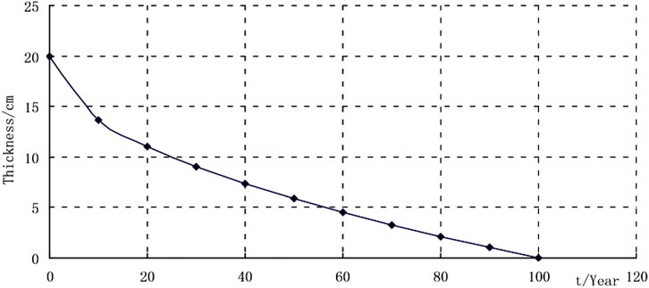
FIGURE 5. Variations in deterioration thickness of the shotcrete with time.
The shotcrete after deterioration lost the bearing capacity, so the deterioration of the shotcrete was simulated by decreasing its thickness in the numerical simulation. Shotcrete and rock mass deteriorated together in the numerical simulation.
3.4 The Process of Numerical Simulation
The excavation procedure was as follows:
(1) In the first step, the geostatic analysis was carried out to apply the gravity of the rock mass, without the lining structure. The in situ stress state was achieved as the initial stress condition for the following simulation.
(2) In the second step, the first slice in the tunnel core was excavated, and the shotcrete was activated. The benching tunneling method is applied and the corresponding footage is 2 m. The longitudinal distance between the up and down bench is 6 m. The shotcrete follows the excavation of the bench.
(3) When excavation is totally completed, the secondary lining starts to be installed. As a safety margin, the secondary lining does not sustain the load of the surrounding rock during tunnel construction.
(4) According to the calculation condition, the rock mass parameters and shotcrete are adjusted as mentioned above.
4 Results and Discussion
The support pressure of the secondary lining and its displacement are shown in Figures 6, 7 respectively. In case 1, the rock mass deteriorated rapidly over the period of 10 years and simultaneously, shotcrete deteriorated gradually. In case 2, the rock mass deteriorated slowly over the period of 100 years and simultaneously, shotcrete deteriorated gradually. In case 3, the rock mass did not deteriorate in the period of 100 years and simultaneously, shotcrete deteriorated gradually.
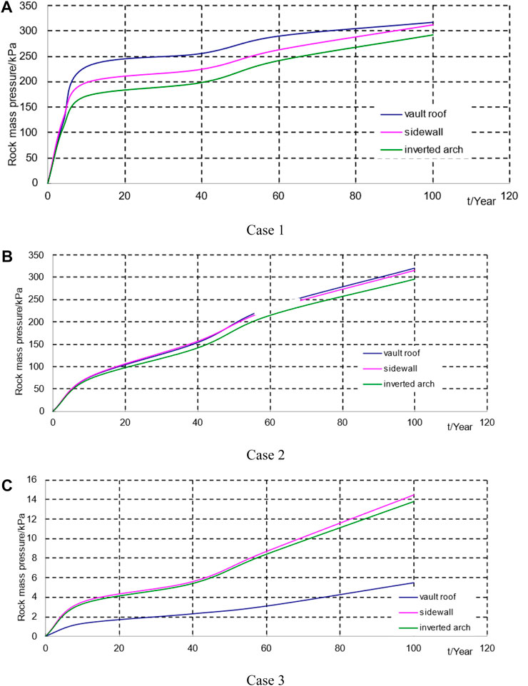
FIGURE 6. Variations in the pressure the secondary lining undertakes with time. (A) Case 1. (B) Case 2. (C) Case 3.
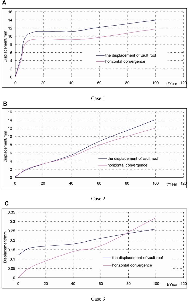
FIGURE 7. Variations in the displacement of the secondary lining with time. (A) Case 1. (B) Case 2. (C) Case 3.
Both the support pressure and displacement of the secondary lining increased gradually during the deterioration of the rock mass and shotcrete. Basically, they shared a common trend, but their increase trends differed during deterioration.
For case 1, the rock mass fully deteriorated in a relatively short time (10 years), and the support pressure of the secondary lining and its displacement increased quickly during deterioration. The rock mass fully deteriorated after 10 years, and shotcrete alone continued to deteriorate gradually. The support pressure of the shotcrete gradually transferred to the secondary lining, and the support pressure and displacement of the secondary lining increased slowly during deterioration. In the 100th year, the maximum support pressure of the secondary lining was 317.7 kPa; the displacement of the vault roof was 13.96 mm, and the horizontal convergence was 11.76 mm.
For case 2, both the rock mass and shotcrete fully deteriorated in a relatively long time (100 years). In the former 60 years, the rock mass deteriorated relatively quickly, increasing the support pressure of the lining, and simultaneously, shotcrete which gradually deteriorated was unable to undertake increased pressure from the rock mass; thus, the support pressure of the secondary lining and its displacement increased in a relatively quick level. In the later 40 years, the rock mass and shotcrete deteriorated at a slower level, while the support pressure of the secondary lining and its displacement increased more slowly. In the 100th year, the maximum support pressure of the secondary lining was 321.2 kPa, the displacement of the vault roof was 14.11 mm, and horizontal convergence was 12.00 mm.
Even though the deterioration processes of case 1 and case 2 given above differed, they reached the same deterioration level eventually (100 years), and the support pressure of the secondary lining and its displacement was basically equal.
For case 3, the rock mass did not deteriorate and shotcrete alone deteriorated with time. The support pressure of the secondary lining mainly came from the support pressure of the shotcrete during construction. In comparison with case 1 and case 2, its pressure and displacement were relatively small and approximated to a linear increase. In the 100th year, the maximum support pressure of the secondary lining was 14.5 kPa; the displacement of the vault roof was 0.26 mm, and the horizontal convergence was 0.32 mm.
The moment and axial force of the secondary lining during deterioration are shown in Figure 8. The axial force gradually increased, and the maximum moment occurred in the spring line. In addition, the vault roof, sidewall, and inverted arch were in tension. The axial force of case 1 and case 2 shared a common distribution, with the bigger ones in the vault roof and inverted arch, and with the smaller ones in the sidewall. In case 3, the smaller one occurred in the vault roof and inverted arch and the bigger one occurred in the sidewall by contrast. Bending moments at the sidewall and inverted arch were much higher, to which attention should be paid. The inner sides of the secondary lining in the two areas were under tension but still within the limit of concrete capacity. Other areas were also within the limit of concrete capacity.
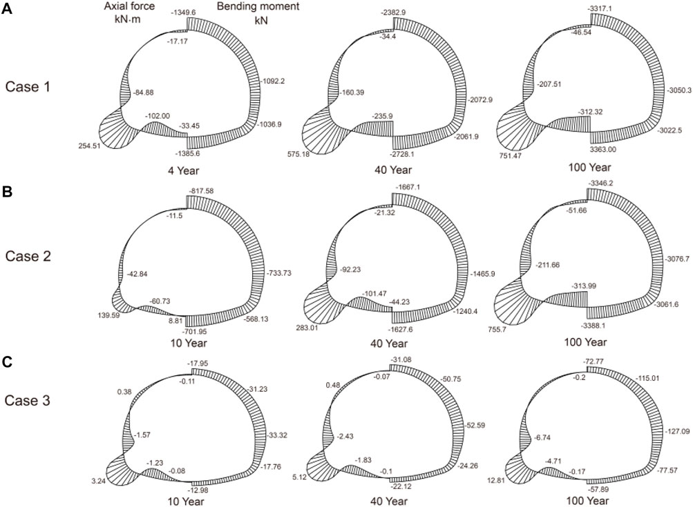
FIGURE 8. Variations in internal force of the secondary lining with time. (A) Case 1. (B) Case 2. (C) Case 3.
The support pressure of the secondary lining would increase significantly since rock mass had deteriorated. The deterioration of the shotcrete would shift pressure from itself to the secondary lining, and shotcrete itself was unable to undertake the left pressure. The deterioration of both the rock mass and shotcrete would significantly increase the support pressure of the secondary lining, leading to an increase in its displacement and internal force and a decrease in the tunnel’s serviceability and safety.
The ratio of the maximum pressure that the supporting structure could bear (
where
where
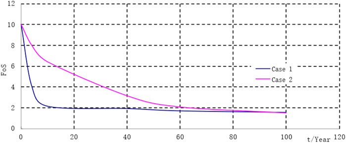
FIGURE 9. FoS evolution (in vault roof) with time.
Being relatively big, the safety factor of case 3 (bigger than 10) was not shown in Figure 9. The initial safety factor is assumed to be 10. As shown in Figure 9, the FoS of case 2 was bigger than that of case 1 in the former time, and the two were basically equal at the end. In case 1, the FoS of the secondary lining decreased significantly because the rock mass deteriorated rapidly in the first 10 years. If special disasters, such as earthquakes and fire accidents, took place during operation time, its safety factor would decrease again, posing a threat to the tunnel’s safe operation.
By comparing the three cases comprehensively, the influence of the shotcrete’s deterioration on the secondary lining was relatively small, and the deterioration of the rock mass was the main influencing factor.
5 Conclusion
Based on numerical simulation, this study carries out a contrastive analysis of the three cases discussed earlier. The following conclusions can be drawn:
(1) The deterioration of both the rock mass and shotcrete would significantly increase the rock pressure on the secondary lining (0–321.2 kPa) and the displacement (0–14 mm). The FoS of the secondary lining was reduced by 85%. In the design of the secondary lining, the influence of the rock pressure increased by the deterioration of the rock mass should be properly considered.
(2) The influence of the shotcrete’s deterioration on the secondary lining was relatively small and the rock pressure the secondary lining undertakes was increased from 0 to 13.8 kPa. The secondary lining only undertakes the support pressure of the shotcrete during construction.
(3) When the rock mass deteriorated rapidly (case 1), the support pressure of the secondary lining would increase rapidly in a relatively short time (10 years) and then incline toward stability; When the rock mass deteriorated slowly (case 2), the support pressure of the secondary lining would gradually increase in a long time (60 years). Also, the two cases were basically equal at the end. Different deterioration characteristics of rock mass have different effects on the secondary lining, and the deterioration characteristics of rock mass should be fully considered in the tunnel maintenance.
It is to be noted that the applicable scope of the conclusion is limited due to the fact that only several conditions are considered in the simulation. Furthermore, no field or laboratory tests have been conducted to verify the numerical simulation. These are the focus of future research.
Data Availability Statement
The original contributions presented in the study are included in the article/Supplementary Material; further inquiries can be directed to the corresponding authors.
Author Contributions
Funding acquisition and formal writing of the work, CK; investigation and data analysis of the work, HW and KZ; review of the work, XG. All authors have read and agreed to the published version of the manuscript.
Funding
This work was supported by the National Natural Science of China (Grant number 52108385) and the Open Project of State Key Laboratory for structural mechanical behavior and system safety of Traffic Engineering jointly constructed by the Ministry and province (KF2021-08).
Conflict of Interest
The authors declare that the research was conducted in the absence of any commercial or financial relationships that could be construed as a potential conflict of interest.
Publisher’s Note
All claims expressed in this article are solely those of the authors and do not necessarily represent those of their affiliated organizations, or those of the publisher, the editors, and the reviewers. Any product that may be evaluated in this article, or claim that may be made by its manufacturer, is not guaranteed or endorsed by the publisher.
References
Aghchai, M. H., Salari, H., and Showkati, A. (2020). Predicting Long-Term Stability of Tunnels Considering Rock Mass Weathering and Deterioration of Primary Support. Tunn. Undergr. Space Technol. 107, 103670.
Ahmad, S. (2003). Reinforcement Corrosion in Concrete Structures, its Monitoring and Service Life Prediction-A Review. Cem. Concr. Compos. 25 (4), 459–471. doi:10.1016/s0958-9465(02)00086-0
Alexander, M., and Beushausen, H. (2019). Durability, Service Life Prediction, and Modelling for Reinforced Concrete Structures - Review and Critique. Cem. Concr. Res. 122, 17–29. doi:10.1016/j.cemconres.2019.04.018
Boidy, E., Bouvard, A., and Pellet, F. (2002). Back Analysis of Time-dependent Behaviour of a Test Gallery in Claystone. Tunn. Undergr. Space Technol. 17 (4), 415–424. doi:10.1016/s0886-7798(02)00066-4
Castellanza, R., Lollino, P., and Ciantia, M. (2018). A Methodological Approach to Assess the Hazard of Underground Cavities Subjected to Environmental Weathering. Tunn. Undergr. Space Technol. 82, 278–292. doi:10.1016/j.tust.2018.08.041
Chandler, R. J., and Apted, J. P. (1988). The Effect of Weathering on the Strength of London Clay. Q. J. Eng. Geol. Hydrogeology 21 (1), 59–68. doi:10.1144/gsl.qjeg.1988.021.01.04
Garber, R. (2003). Design of Deep Galleries in Low Permeable Saturated Porous Media. Thesis EPFL no. 2721. Lausanne: Ecole Polytechnique Federale de Lausanne.
Graham, J., and Au, V. C. S. (1985). Effects of Freeze-Thaw and Softening on a Natural Clay at Low Stresses. Can. Geotech. J. 22 (1), 69–78. doi:10.1139/t85-007
Gullà, G., Mandaglio, M. C., and Moraci, N. (2006). Effect of Weathering on the Compressibility and Shear Strength of a Natural Clay. Can. Geotechnical J. 43 (6), 618–625.
Jiang, L., and Niu, D. (2016). Study of Deterioration of Concrete Exposed to Different Types of Sulfate Solutions under Drying-Wetting Cycles. Constr. Build. Mater. 117, 88–98. doi:10.1016/j.conbuildmat.2016.04.094
Khanlari, G. R., Heidari, M., and Momeni, A. A. (2012). Assessment of Weathering Processes Effect on Engineering Properties of Alvand Granitic Rocks (West of Iran), Based on Weathering Indices. Environ. Earth Sci. 67, 713–725. doi:10.1007/s12665-011-1518-6
Ladanyi, B. (1980). “Direct Determination of Ground Pressure on Tunnel Lining in a Non-linear Viscoelastic Rock,” in Proceedings of the 13th Canadian rock mechanics symposium, Montreal (CIM), 126–132.
Ladanyi, B. (1974). “Use of the Long-Term Strength Concept in the Determination of Ground Pressure on Tunnel Linings,” in Advances in rock mechanics: reports of current research, Proceedings of the 3rd international congress on rock mechanics, Denver (National Academy of Sciences), 1150–1156.
Lei, M., Peng, L., Shi, C., and Wang, S. (2013). Experimental Study on the Damage Mechanism of Tunnel Structure Suffering from Sulfate Attack. Tunn. Undergr. Space Technol. 36, 5–13. doi:10.1016/j.tust.2013.01.007
Liu, X., Jin, M., Li, D., and Zhang, L. (2018). Strength Deterioration of a Shaly Sandstone under Dry-Wet Cycles: a Case Study from the Three Gorges Reservoir in China. Bull. Eng. Geol. Environ. 77 (4), 1607–1621. doi:10.1007/s10064-017-1107-3
Lyu, H., Gu, J., Li, W., and Liu, F. (2020). Analysis of Compressibility and Mechanical Behavior of Red Clay Considering Structural Strength. Arabian J. Geosciences 13 (11), 1–11. doi:10.1007/s12517-020-05352-4
Mert, E. (2014). An Artificial Neural Network Approach to Assess the Weathering Properties of Sancaktepe Granite. Geotech. Geol. Eng. 32 (4), 1109–1121. doi:10.1007/s10706-014-9785-0
Momeni, A., Hashemi, S. S., Khanlari, G. R., and Heidari, M. (2017). The Effect of Weathering on Durability and Deformability Properties of Granitoid Rocks. Bull. Eng. Geol. Environ. 76 (3), 1037–1049. doi:10.1007/s10064-016-0999-7
Nguyen, V. H. (2005). Couplage degradation chimique-comportement en compression du be´ton. Thesis dedoctorat. Paris: Ecole Nationale des Ponts et Chaussees.
Panet, M. (1979). “Time-dependent Deformations in Underground Works,” in Proceedings of the 4th international congress on rock mechanics, Montreux, Balkema, Rotterdam, 2-8 Sept 1979, 279–290.
Sandrone, F., and Labiouse, V. (2010). Analysis of the Evolution of Road Tunnels Equilibrium Conditions with a Convergence-Confinement Approach. Rock Mech. Rock Eng. 43 (2), 201–218. doi:10.1007/s00603-009-0056-y
Serafim, J. L., and Pereira, J. P. (1983). “Considerations of the Geomechanics Classification of Bieniawski,” in Proc. of the International Symposium on Engineering Geology and Underground Construction, Lisbon, A.A. Balkema, Rotterdam, the Netherlands, 1133–1142.
Sola, E., Ožbolt, J., Balabanić, G., and Mir, Z. M. (2019). Experimental and Numerical Study of Accelerated Corrosion of Steel Reinforcement in Concrete: Transport of Corrosion Products. Cem. Concr. Res. 120, 119–131. doi:10.1016/j.cemconres.2019.03.018
Sulem, J., Panet, M., and Guenot, A. (1987). An Analytical Solution for Time-dependent Displacements in a Circular Tunnel. Int. J. Rock Mech. Min. Sci. Geomechanics 24 (87), 155–164. doi:10.1016/0148-9062(87)90523-7
Swoboda, G., Mertz, W., and Beer, G. (1987). Rheological Analysis of Tunnel Excavations by Means of Coupled Finite Element (Fem)–boundary Element (BEM) Analysis. Int. J. Numer. Anal. Methods Geomechanics 11. doi:10.1002/nag.1610110202
Tating, F., Hack, R., and Jetten, V. (2013). Engineering Aspects and Time Effects of Rapid Deterioration of Sandstone in the Tropical Environment of Sabah, Malaysia. Eng. Geol. 159, 20–30. doi:10.1016/j.enggeo.2013.03.009
Tugrul, A. (1998). The Application of Rock Mass Classification Systems to Underground Excavation in Weak Limestone, Atatürk Dam, turkey. Eng. Geol. 50, 337–345.
Ündül, Ö., and Tuğrul, A. (2012). The Influence of Weathering on the Engineering Properties of Dunites. Rock Mech. Rock Eng. 45, 225–239. doi:10.1007/s00603-011-0174-1
Usman, M., and Galler, R. (2013). Long-term Deterioration of Lining in Tunnels. Int. J. Rock Mech. Min. Sci. 64 (6), 84–89. doi:10.1016/j.ijrmms.2013.08.028
Wong, L. N. Y., Maruvanchery, V., and Liu, G. (2016). Water Effects on Rock Strength and Stiffness Degradation. Acta Geotech. 11 (4), 713–737. doi:10.1007/s11440-015-0407-7
Yokozeki, K., Watanabe, K., Sakata, N., and Otsuki, N. (2004). Modeling of Leaching from Cementitious Materials Used in Underground Environment. Appl. Clayence 26 (1), 293–308. doi:10.1016/j.clay.2003.12.027
Yoshida, N., and Adachi, T. (2010). Fe Analysis of Time-dependent Instability of Cut Slopes in Clay Shale. American Society of Civil Engineers.
Yoshida, N., Morgenstern, N. R., and Chan, D. H. (1990). A Failure Criterion for Stiff Soils and Rocks Exhibiting Softening. Can. Geotech. J. 27 (2), 195–202. doi:10.1139/t90-023
Yoshida, N., Nishi, M., Kitamura, M., and Adachi, T. (1997). Analysis of Mudstone Deterioration and its Effect on Tunnel Performance. Int. J. Rock Mech. Min. Sci. 34 (3), 353. e1–353.e19. doi:10.1016/s1365-1609(97)00289-x
Keywords: degradation, time-dependent, numerical simulation, rock pressure, safety factor
Citation: Kong C, Wang H, Zhao K and Gao X (2022) Numerical Simulation of Long-Term Deterioration of Rock Mass Supported by Shotcrete Lining. Front. Earth Sci. 10:891084. doi: 10.3389/feart.2022.891084
Received: 07 March 2022; Accepted: 19 April 2022;
Published: 24 May 2022.
Edited by:
Chaojun Jia, Central South University, ChinaReviewed by:
Shijun Chen, East China University of Technology, ChinaZhihui Wan, Southeast University, China
Copyright © 2022 Kong, Wang, Zhao and Gao. This is an open-access article distributed under the terms of the Creative Commons Attribution License (CC BY). The use, distribution or reproduction in other forums is permitted, provided the original author(s) and the copyright owner(s) are credited and that the original publication in this journal is cited, in accordance with accepted academic practice. No use, distribution or reproduction is permitted which does not comply with these terms.
*Correspondence: Haiyan Wang, wanghy@njtech.edu.cn; Kai Zhao, zhaokai@njtech.edu.cn