Experimental Study on Heat Loss of a Single Screw Expander for an Organic Rankine Cycle System
 Wei Wang
 Li-li Shen1,2
 - 1Key Laboratory of Enhanced Heat Transfer and Energy Conservation, Ministry of Education, College of Environmental and Energy Engineering, Beijing University of Technology, Beijing, China
- 2Key Laboratory of Heat Transfer and Energy Conversion, Beijing Municipality, College of Environmental and Energy Engineering, Beijing University of Technology, Beijing, China
For displacement expanders, the irreversible losses include leakage, friction, heat dissipation, and flow resistance. Currently, the research on the heat loss of expanders is scarce, especially with regards to experimental studies. In this paper, the experimental research on the heat loss of the single screw expander (SSE) for the Organic Rankine Cycle was carried out under different working conditions, in the summer and winter, respectively. In each set of experiments, there were five cases, and the temperatures of the working fluids at the inlet of the expander were 83, 93, 103, 113, and 123°C, respectively. The heat removed by the lubricating oil was also measured throughout the experimental period. The experimental results showed that the amount of heat loss was not comparable to the output power and enthalpy difference between the inlet and outlet of the SSE. The proportion of the heat dissipated by the casing was only 30% ranging from 0.11 to 0.28 kW. Comparing the experimental results in summer and winter, the heat loss in summer was lower than in winter, but the variation in output power showed an opposite trend. It was also shown that heat loss was not a main factor affecting the performance of SSEs.
Introduction
Organic Rankine Cycle (ORC) is one of the most important technologies for low temperature waste heat utilization (Quoilin et al., 2013). Many experimental results show that the expander performance is an important factor affecting the thermal efficiency of small ORC systems. According to the principle of thermodynamics, irreversible loss is the key factor in expander performance. For displacement expanders, irreversible loss primarily includes leakage, mechanical friction, flow loss, and heat loss. Obviously, the influence of different losses is coupled. It can be seen that the mechanism of irreversible loss for expanders is complex. Due to the adiabatic process, heat loss is typically neglected for heat engines. However, the influence of heat loss in low capacity expanders may be prominent, and compared with heat transfer in compressors, the research on heat loss for small capacity expanders is insufficient and incomplete.
Currently, a great deal of research on heat transfer in compressors has been performed. C. Willich et al. presented a new heat transfer model for a reciprocating compressor, and the influence of valve actuation was considered. According to the simulation results, the exhaust pressure and velocity of the piston shows obvious effects on exhaust temperature (Willich and White, 2017). N Stosic established the heat transfer model of a twin screw compressor. When steady state was obtained, the axial temperature of the compressor casing and rotor was close to a linear distribution (Stosic, 2015). According to the geometric characteristics of a scroll compressor, Pereira and Deschamps (2012) established a heat transfer model “near the wall” in a scroll compressor using the finite volume method and analyzed the results of the convective heat transfer model of high and low Reynolds numbers. Zhang et al. (2003a, 2003b) established and verified the heat transfer model of a rolling rotor compressor and analyzed the influence of various factors, such as inlet temperature, evaporation, and condensation temperature, on the heat loss between the casing and environment. Li et al. (1992) studied the effects of oil atomization on the exhaust gas temperature. In addition, Zhao et al. (2016) analyzed the heat transfer of the single screw compressor under oil atomization based on the fuzzy random wavelet finite element methods, where the oil droplet size affected the heat transfer between the gas and lubricating oil, and as the diameter of the oil droplet decreased, the exhaust temperature also decreased. Due to similar mechanical configurations, these researches could be correlated to the heat loss in expanders. However, heat loss plays different roles in thermodynamics processes of expanders and compressors, so the influence of heat transfer was also different. For compressors, heat dissipation could reduce compression work. For the expander, the temperature and pressure of the working fluid was reduced by heat loss.
Presently, there have been some articles on heat loss of small capacity expanders, but the work is still preliminary, especially for experimental studies. The external heat loss of a turbine was studied by Li, and the inlet and exhaust temperatures were 100 and 64.5°C, respectively, with a heat loss of 94.5 W, which accounted for 2.9% of the turbine design power. Also, the fitting formula of convection and radiation heat transfer was generated (Li et al., 2011). Liu et al. established a thermodynamics model of the working process for scroll expanders, which included the heat transfer model and compared the simulation results with the experimental data. The results showed that the calculated output power was higher than the experimental data at low rotational speed and lower at high rotational speed (Guangbin et al., 2010). Ayachi et al. established and analyzed a semi-empirical model of a scroll expander in the Brayton Cycle, where the model included the effects of leakage, pressure drop, and heat transfer. The model was then modified experimentally (Ayachi et al., 2016). Lemort et al. (2009) established and modified the semi-empirical model of the single screw expander (SSE) for the ORC system, and the results showed that the isentropic efficiency decreased about 3.75% compared with the assumption of only negligible heat loss. It should be noted that heat removed by the lubricating oil was not considered. On this foundation, Giuffrida et al. fine-tuned the semi empirical model, where they did not consider lubricating oil heat transfer. The expander was assumed to be an isothermal wall, and the heat transfer during the intake process, exhaust process, and the heat transfer between the wall and the environment were studied, and no heat was exchanged during the expansion process. The results showed that with the decrease in the expansion ratio, heat loss between the expander to the external environment gradually increased, and the proportion was about 7%–67% of the ratio of the heat loss to shaft power, and based on the data given, it could be roughly estimated that when the expansion ratio was less than 8 and greater than 3, the expander heat loss to the external environment accounted for about 6%–24.8% of the enthalpy difference between the import and export. However, this model merely considered the heat loss of the working fluid dissipated into the external environment, and the heat loss caused by the leakage between the working fluids of each screw groove was not considered (Giuffrida, 2017).
Summarizing the literature, the numerical analysis on the heat loss of expanders primarily depended on semi-empirical models, but the model did not directly conform to the actual working process. For example, the total heat loss of working fluid should include the heat carried away by lubricating oil and the heat loss due to mixing of the working fluid during the leakage process, but the model could not give the corresponding explanation (Lemort et al., 2009; Giuffrida, 2017). SSE was one of the most suitable expander types for a small-middle capacity ORC system. However, the experimental research on the heat loss of the SSE is still lacking. This paper has carried on the experimental research on the heat loss of the SSE for the ORC system under different working conditions and explored the influence of heat loss under different conditions on the performance of the expander. This work could provide basic data for further research on performance optimization of the SSE.
Heat Loss
Thermodynamics Process
In the complete thermodynamics process of the SSE, heat loss is referred to as the heat dissipated into the environment and consists of two components: one includes the heat dissipation at the intake pipe, expander casing, and discharge pipe, and the other is the heat dissipation of the lubricating oil. Due to insulation on the pipes of the intake and discharge, heat dissipation can be ignored. Hence, at equilibrium, the total heat loss of SSE can be obtained by the formula as follows:
where
To investigate the effects of heat loss on the performance of SSEs, we defined the ratio of the total heat loss to shaft power as the heat loss rate:
where
Calculation of Heat Loss
The Casing Heat Loss
The external heat loss of the expander casing included convection heat loss, radiation loss, and conduction loss. Due to the small contact area between the casing and angle bracket, the heat conductivity was small. Therefore, we have only analyzed the convection heat loss and radiation loss.
The expander casing heat loss is the sum of the convective and radiative heat losses:
where
The method of calculating heat transfer is as follows:
(1) Convection heat loss
The convection heat loss was generally calculated by the Newton cooling formula:
where Si is the area of each surface, m2; αc is the convective heat transfer coefficient of each surface, W⋅m−2⋅K−1; d is the characteristic dimensions, m; β is the thermal expansion coefficient, K−1; ρ is the density of air, kg⋅m−3; λ is the thermal conductivity, W⋅m−1⋅K−1; μ is the coefficient of kinetic viscosity, Pa·s; cp is the isobaric specific heat capacity, kJ⋅kg−1⋅K−1; Te is the environmental temperature, K. These parameters were obtained using the REFPROP software. According to the geometrical characteristics of the casing of the SSE, it can be divided into three typical surfaces: vertical plane, horizontal plane, and horizontal cylinder.
1) Vertical plane
According to each vertical surface temperature and qualitative dimensions, the Gr can be calculated, which is less than 107, so the mode of heat transfer is the natural laminar convection heat transfer. The Nu at each surface was calculated by the experimental correlation formula of the laminar natural convection heat transfer of a vertical plate (Churchill, 1975):
2) Horizontal plane
When the hot surface faced up, the Nu could be calculated by (Li et al., 2011):
and when the hot surface faced down (Li et al., 2011):
3) Horizontal cylinder
The Nu of the horizontal cylinder surface could be calculated by the following experimental correlation formula (Morgan, 1975):
(2) Radiative heat loss
The SSE casing was made of gray iron. We could determine that the blackness (ε) of this highly oxidized rough surface was 0.95 when the range of the temperature was between 40 and 250°C. Radiative heat loss could be approximated by:
where Ti is the temperature of each surface, K; Te is the environmental temperature, K.
Lubricating Oil Heat Loss
Lubricating oil heat loss was calculated by the temperature of the oil inlet and outlet.
where
Heat Loss Proportion
We defined the ratio of the casing heat loss to the total heat loss as the heat loss proportion. The formula is shown as:
Experiment System
Circulation Loop
Figure 1 shows the circulation process chart of the ORC experimental test. The photo of the experimental table of the ORC system is shown in Figure 2.
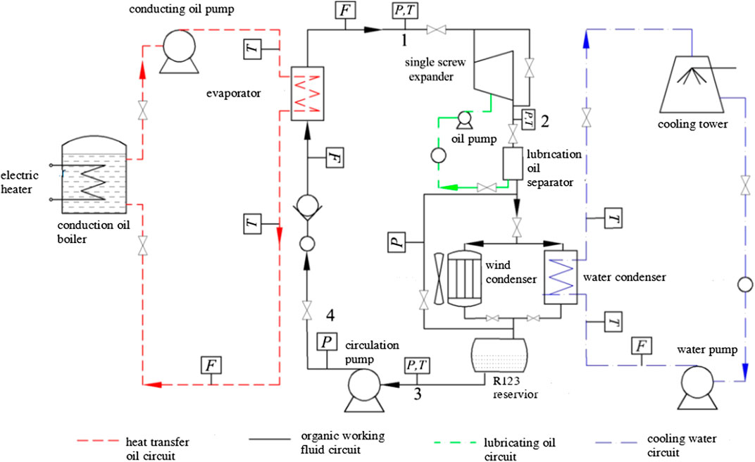
FIGURE 1. Schematic diagram of the experimental Organic Rankine Cycle system.
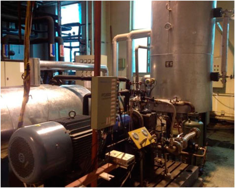
FIGURE 2. The experiment table of Organic Rankine Cycle system.
Experimental Measurement
Sensor Parameter
(1) Temperature sensor: One type is a standard thermocouple of grade A 100 Pt. It is used to measure the temperature of the working fluid, cooling water, and lubricating oil in different pipelines. The measurement range was 0–200°C and the accuracy was ±0.25°C. Another type is a K-patch thermocouple, and it is used to measure the temperature of the casing. The measurement range was −50 to 150°C, with an accuracy of ±0.5°C. The thermocouples were installed on the surface of the expander using an adhesive.
(2) Pressure sensor: two pressure sensors of CYB-20S were used; the measurement range of each were −0.1 to 1.6 MPa (inlet) and –0.1 to 0.5 MPa (outlet), with an accuracy of ±0.5%.
(3) Flow meter: A Vortex flow meter was used to measure the volume flow rate of the working fluid at the inlet of the expander, where the flow range was 0–32 m3⋅h−1 and the accuracy was ±0.5%.
(4) Torque and rotational speed: both were measured by AC electric dynamometer. The measurement range and accuracy of the torque are 0–8,000 rpm and ±0.5%, and of the rotational speeds are 0–200 N·m and ±0.5%.
Temperature Measurement
SSE prototype is independently developed by our laboratory. The main structural parameters of SSE prototype are shown in Table 1.
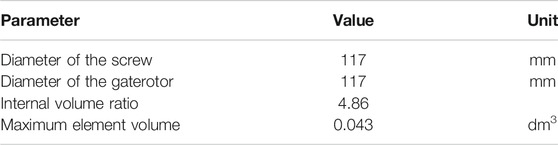
TABLE 1. Parameters of the SSE prototype.
According to the characteristics of the symmetry of the casing, the casing could be divided into eight parts, A–G, which are marked in Figure 3.
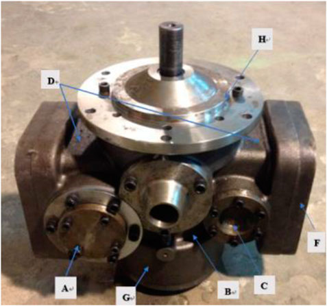
FIGURE 3. Surface area division of expander casing.
Details of each area are shown in Table 2. The surfaces of A and C were connected with the gaterotor bearing. The B surface was one of the surfaces of the working chamber. The surfaces of A, C, D, E and F were in contact with the exhaust working fluid. The H and G surfaces were connected with the screw bearing. Due to the symmetry of the expander casing, the temperature of the casing also presented a symmetrical distribution, so the arrangement of the temperature sensor could be simplified symmetrically. In Figure 3, the A, B, C, D, E, F, G and H surfaces were each installed with a temperature sensor, to measure temperature locally.

TABLE 2. Introduction of each area.
Performance Parameter
(1) Shaft powerIn the experiment, the shaft power was typically obtained by calculating the real-time data of the torque (N) and rotational speed (n) of the expander:
where N is the torque, N·m; and n is the rotational speed, r⋅min−1.
(2) Shaft efficiencyShaft efficiency (ηs) is equal to the ratio of the actual shaft power (Pe) to the ideal work of the isentropic process.
(3) Expansion ratioThe expansion ratio is defined as the ratio of the pressures at the inlet and outlet.
where pin is the inlet pressure, bar; pout is the outlet pressure, bar.
Results and Analysis
In this study, R123 was used as the working fluid. To investigate the effects of environmental conditions on ORC performance, two sets of experiments were carried out in winter and summer. In each set of experiments, the inlet state parameters of the working fluid were varied, and the working conditions of other components remained unchanged. The time of the summer experiment was from 4th August 2017 to 26th August 2017. During the experiment, the ambient temperature was between 32 and 34°C. The time of the winter experiment was from 20th January 2018 to 3rd February 2018. During the experiment, the ambient temperature was between −2 and 1°C. Based on the above experimental conditions, five groups of experiments were carried out in each season, and the temperatures of the working fluids at the inlet of the expander were 83, 93, 103, 113, and 123°C, respectively.
Thermal Equilibrium
Figure 4 shows the variation of temperature with time at different measuring points, and the experimental condition was 123°C at the inlet temperature in summer. From the figure, it shows that the temperature of each point was stable when the operation time of the expander exceeded 2 h. At this time, the heat transfer process of the components of the expander could be considered stable.
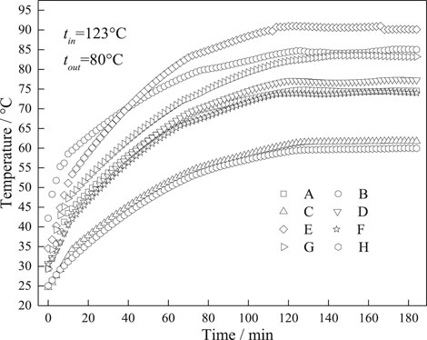
FIGURE 4. The variation of temperature with time at different measuring points.
Performance
The parameters of working fluids at various experimental conditions are shown in Table 3. It can be seen that the inlet pressure and outlet temperature in summer are slightly higher than that in winter. The outlet pressure in summer is obviously higher than that in winter, so it is indicated that the expansion ratio in summer is lower than that in winter. Because the condensation temperature in winter is relatively lower, so the backpressure in winter is lower than that in summer. The mass flow rate in summer is higher than that in winter, except for 83°C condition. Due to higher expansion ratio, the volume flow rate in winter is higher than that in summer. With the decrease of inlet temperature, the density difference between summer and winter conditions becomes small. In the condition of 83°C, this phenomenon occurs.
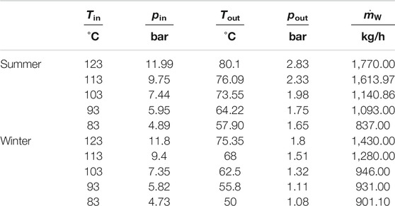
TABLE 3. Parameters of working fluids at different experimental conditions.
Figure 5 shows the shaft power variation with inlet temperature in summer and winter. The relative error of shaft power is 0.71%. With the increase of temperature of the inlet condition, the shaft powers of the two seasons increased. Under the same inlet conditions in winter, the shaft power was higher than in summer. From Table 3, the mass flow rate of the working fluid in winter was lower than the same working conditions in summer, except at 83°C. It indicated that the leakage of the SSE in winter was lower than the same working condition in summer. For the above reasons, this indicated that the SSE had better performance in winter.
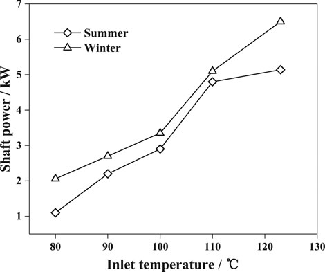
FIGURE 5. The variation of shaft power with inlet temperature.
Figure 6 shows the variation of the expander ratio with inlet temperature in summer and winter. The relative error of shaft power is 0.71%. With the increase of the inlet temperature, the expansion ratio increased, and the expansion ratio in winter was significantly higher than in summer. Also, in summer, the growth rate of the expansion ratio decreased gradually, and the growth trend tended to be flat. However, in winter, the changing trend of the expansion ratio had an inflection point when the inlet temperature was 100°C, and its value increased significantly. Unlike other displacement type expanders, the expansion ratio of SSEs was significantly affected by back pressure. The phenomenon of “under expansion” did not occur in the actual conditions (Lei et al., 2016). For a SSE with definite structure, the internal volume ratio was also fixed at 4.86. However, the expansion ratio can exceed six in winter. Due to the unique structure, the thermodynamic system of the SSE was closer to an open system, so back pressure was the key factor for the expansion ratio. The main factors affecting back pressure included condensation pressure and flow resistance of the exhaust pipelines. First, since the ambient temperature in summer was higher than in winter, the condensation temperature was higher in summer, and the condensation pressure was also higher. Second, owing to the higher exhaust pressure in summer, the flow loss of the exhaust pipeline was greater. Moreover, with the increase in inlet pressure, the trend was more obvious. Hence, the expansion ratio in winter was higher than in summer, and the rate of increase was also faster in summer with the increase of inlet temperature.
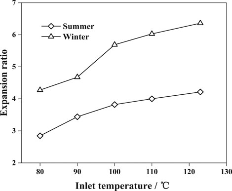
FIGURE 6. The variation of the expander ratio with inlet temperature.
Figure 7 shows the variation of shaft efficiency with inlet temperature in summer and winter. With the increase in temperature of the inlet conditions, the shaft efficiency in summer increased rapidly and then decreased slightly, while the shaft efficiency in winter increased gradually. Under the same inlet conditions, the shaft efficiency in winter was higher than in summer. From Figures 5 and 6, the increased rate of shaft power and expansion ratio in summer gradually decreased with the temperature increase at the inlet. If the increased rate of shaft power was lower than that of ideal work of the isentropic process, the shaft efficiency could decrease. According to thermodynamics principles, the increase of ideal enthalpy difference was faster than actual enthalpy difference with the increase of inlet temperature. Therefore, the shaft efficiency slightly decreased in the 123°C condition of summer. Summarizing the above experimental results, it could be concluded that the performance of the SSE in winter was better than in summer.
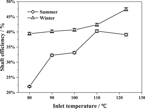
FIGURE 7. The variation of shaft efficiency with inlet temperature in summer and winter.
Heat Loss
Casing Heat Loss
Tables 4 and 5 show the average temperature of each surface under different inlet conditions when the temperature reached steady state.
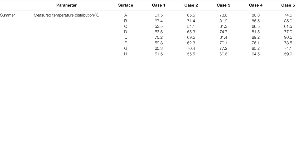
TABLE 4. Each surface temperature at different inlet temperatures in summer.
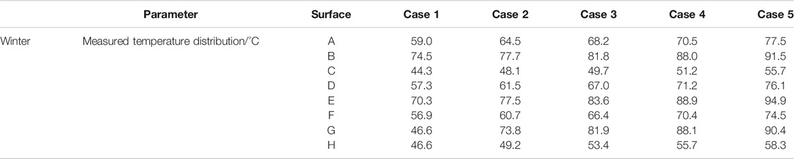
TABLE 5. Surface temperature at different inlet temperatures in winter.
The trend of casing heat loss with inlet temperature is shown in Figure 8. The casing heat loss in winter was higher than in summer. From Tables 4and5, the average temperature of the casing in summer was higher than that in winter at the same inlet temperature, but because of the lower ambient temperature in winter, the heat loss in winter was higher than in summer. From Figure 8, it was shown that the casing heat loss was 0.11–0.19 kW in summer conditions, and 0.18–0.28 kW in winter conditions.
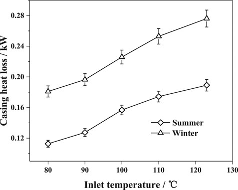
FIGURE 8. The variation of expander casing heat loss with inlet temperature.
Lubricating Oil Heat Loss
Lubricating oil heat loss was an important factor in heat dissipation from the working fluid. Since the lubricating oil and the working fluid were in contact with each other and heat exchange occurred, the energy of the working fluid itself reduced, thereby affecting the working ability of the working fluid.
The trend of lubricating oil heat loss with inlet temperature is shown in Figure 9. With the increase of inlet temperature, the lubricating oil heat loss increased accordingly. It was obvious that lubricating oil absorbed more heat from the working fluid and the structure due to higher inlet temperature. For similar reasons of casing heat dissipation, the lubricating oil heat loss in winter was higher than that in summer. From Figure 9, it shows that lubricating oil heat loss was 0.27–0.5 kW in summer conditions, and 0.35–0.64 kW in winter conditions. This indicates that the heat removed by the lubricating oil was significantly higher than the casing heat dissipation.
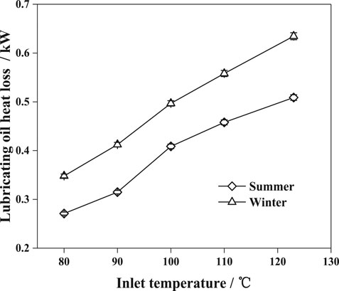
FIGURE 9. The variation of the lubricating oil heat loss with inlet temperature.
Heat Loss Proportion
The change in heat loss proportion with inlet temperature is shown in Figure 10. With the increase of inlet temperature, the proportion of casing heat dissipation to total heat loss slightly decreased whether in summer or winter. At the same inlet conditions, the proportion in winter was slightly higher than that in summer. From the figure, it shows that the heat loss proportion was 27%–29.5% in summer conditions, and 30%–33.5% in winter conditions. For different working conditions, the rough number of the heat loss proportion was about 30%. It can be seen that the heat loss of lubricating oil is main heat loss of the SSE, and the influence is also increasing with the improvement of working conditions. It is indicated that the influence of lubricating oil heat dissipation should be considered in the irreversible analysis for SSEs, even for other type expanders with lubricating oil.
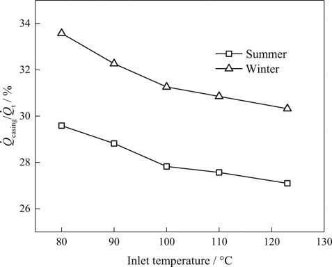
FIGURE 10. The variation of heat loss proportion with inlet temperature.
Performance Impact
The change in heat loss rate with inlet temperature is shown in Figure 11.
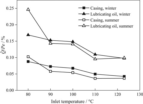
FIGURE 11. The variation of heat loss rate with inlet temperature.
With the increase of inlet temperature, the values gradually decreased whether in summer or winter. The reason for this phenomenon is that the performance of expander was improved with the working condition, and the increase of power was faster than that of heat loss. For the same inlet conditions, the value in summer was slightly lower than that in winter, expect for the case of 80°C. The reason is that the case in summer was worse, and the expansion ratio lower than 3. It is indicated that over expansion occurs, and the situation in summer is more serious than that in winter. In this figure, the casing heat loss rate of winter and summer were 4.25–8.79% and 3.68–10.25% respectively, the lubricating oil heat loss rate of winter and summer were 9.76–16.89% and 9.90–24.63% respectively. From the result, it can be seen that the heat loss rate was almost the same in most working conditions, and the rough number of the total heat loss rate was lower than 15% near rated condition. It was indicated that the influence of ambient temperature on the heat loss rate was very small, but working condition as very significant.
Summarizing the above experimental results, for the amount of heat loss, it was found that both of working condition and ambient temperature could influence it. On one hand, low ambient temperature increased the temperature difference of heat transfer, and then enhanced heat dissipation. Meanwhile, since the surface area of heat dissipation and the heat transfer coefficient were constant, the temperature difference between the surface and ambient environment increased with the inlet temperature. However, for the value of heat loss rate, it was found that working condition was a key factor for the performance of SSEs, and ambient temperature was not an important factor. On another hand, low ambient temperature could increase the temperature difference of heat transfer and the amount of heat loss. But low ambient temperature could also decrease back pressure and increase expansion ratio, so the output power could increase accordingly. It was indicated that improving the expansion ratio was far more important than increasing the temperature difference between the casing of the expander and ambient conditions. So, it could be experimentally concluded that heat loss was not the main irreversible loss for SSEs.
Conclusion
In this study, experimental research on heat loss of a SSE prototype under different working conditions was performed, and the main conclusions were as follows:
(1) The performance of the SSE in winter conditions was better than in summer conditions, but the heat loss trended in an opposite manner. It was indicated that heat loss was not the main factor affecting the performance of SSEs.
(2) The heat removed by the lubricating oil was higher than the heat dissipated by the casing. The proportion of casing heat loss was around 30% in various working conditions. The amount of casing heat loss was from 0.11 to 0.28 kW in these conditions.
(3) At the same inlet temperature, the heat loss rate in winter was slightly different to that in summer. It was indicated that the influence of ambient temperature on the heat loss rate was very small.
(4) When the SSE reached rated condition, the heat loss rate as less than 15%, and the proportion of casing and lubricating oil were less than 5% and 10%, respectively.
(5) Decreasing ambient temperature could reduce backpressure and increase the heat transfer temperature difference of the heat loss, which could then increase the expansion ratio and heat loss amount. Comparing various factors comprehensively, reducing backpressure was the most effective measure for performance improvement of the SSE.
Data Availability Statement
All datasets presented in this study are included in the article/supplementary material.
Author Contributions
WW contributed to the conception of the study; RC performed the experiment; WW, LS, and RC performed the data analyses and wrote the manuscript; YW and CM helped perform the analysis with constructive discussions.
Funding
This work was supported by National Natural Science Foundation of China [Grant number 51706004].
Conflict of Interest
The authors declare that the research was conducted in the absence of any commercial or financial relationships that could be construed as a potential conflict of interest.
Nomenclature
Variables
d characteristic dimension (m)
Gr Grashov number
m mass flow rate (kg⋅s−1)
n rotational speed (r⋅min−1)
N torque (N·m)
Nu Nusselt number
Pe output power (kW)
Pr Prandtl number
Q heat flux (kW)
Ra Rayleigh number
S area (m2)
T Kelvin temperature (K)
Greek symbols
Subscripts
c convection
casing expander casing
e environment
i surface number
in inlet
oil lubricating oil
out outlet
r radiation
s isentropic
s shaft
t total
w working fluid
References
Ayachi, F., Ksayer, E. B., Neveu, P., and Zoughaib, A. (2016). Experimental investigation and modeling of a hermetic scroll expander. Appl. Energy. 181 (1), 256–267. doi:10.1016/j.apenergy.2016.08.030
Churchill, S. W. (1975). Transient laminar free convection from a heated vertical plate. Lett. eat Mass Tran. 2 (3), 311–314. doi:10.1016/0094-4548(75)90014-4
Giuffrida, A. (2017). Improving the semi-empirical modelling of a single-screw expander for small organic rankine cycles. Appl. Energy. 193 (1), 356–368. doi:10.1016/j.apenergy.2017.02.015
Guangbin, L., Yuanyang, Z., Liansheng, L., and Pengcheng, S. (2010). Simulation and experiment research on wide ranging working process of scroll expander driven by compressed air. Appl. Therm. Eng. 30 (14–15), 2073–2079. doi:10.1016/j.applthermaleng.2010.05.015
Lei, B., Wang, W., Wu, Y.-T., Ma, C.-F., Wang, J.-F., Zhang, L., et al. (2016). Development and experimental study on a single screw expander integrated into an Organic Rankine Cycle. Energy 116, 43–52. doi:10.1016/j.energy.2016.09.089
Lemort, V., Quoilin, S., Cuevas, C., and Lebrun, J. (2009). Testing and modeling a scroll expander integrated into an Organic Rankine Cycle. Appl. Therm. Eng. 29 (14–15), 3094–3102. doi:10.1016/j.applthermaleng.2009.04.013
Li, H., Feng, H., and Jin, G. (1992). Influence on the exhaust temperature of single screw compressor under lubricating oil atomization. J. Fluids Eng. 20 (8), 14–16.
Li, J., Pei, G., Li, Y., and Ji, J. (2011). Evaluation of external heat loss from a small-scale expander used in organic rankine cycle. Appl. Therm. Eng. 31 (14–15), 2694–2701. doi:10.1016/j.applthermaleng.2011.04.039
Morgan, V. T. (1975). The overall convective heat transfer from smooth circular cylinders. Adv. Heat Tran. 11, 199–264. doi:10.1016/s0065-2717(08)70075-3
Perevaira, E. L. L., and Deschamps, C. J. (2012). A numerical study of convective heat transfer in the compression chambers of scroll compressors. International Compressor Engineering Conference at Purdue. Available at: https://docs.lib.purdue.edu/icec/2085.
Quoilin, S., Broek, M. V. D., Declaye, S., Dewallef, P., and Lemort, V (2013). Techno-economic survey of Organic Rankine Cycle (ORC) systems. Renew. Sustain. Energy Rev. 22, 168–186. doi:10.1016/j.rser.2013.01.028
Stosic, N. (2015). On heat transfer in screw compressors. Int. J. Heat Fluid Flow. 51, 285–297. doi:10.1016/j.ijheatfluidflow.2014.10.026
Willich, C., and White, A. J. (2017). Heat transfer losses in reciprocating compressors with valve actuation for energy storage applications. J. Energy Storage. 14 (S1), 322–328. doi:10.1016/j.est.2017.07.024
Zhang, H.-j., Cai-qiu, Y., Lu, J., Liu, Y., Chen, L., and Li, Y. (2003a). Simulation and investigation on rolling piston type rotary compressor. Low Temp. Spec. Gas. 21 (6), 12–15. doi:10.3969/j.issn.1007-7804.2003.06.004
Zhang, H.-j., Cai-qiu, Y., Lu, J., Liu, Y., Chen, L., and Li, Y. (2003b). Simulation of heat exchange on rolling piston type rotary compressor. Low Temp. Spec. Gas. 21 (4), 7–9. doi:10.3969/j.issn.1007-7804.2003.04.003
Keywords: organic rankine cycle, single screw expander, temperature measurement, total heat loss, heat dissipation of lubricating oil
Citation: Wang W, Shen L-l, Chen R-m, Wu Y-t and Ma C-f (2020) Experimental Study on Heat Loss of a Single Screw Expander for an Organic Rankine Cycle System. Front. Energy Res. 8:587726. doi: 10.3389/fenrg.2020.587726
Received: 05 August 2020; Accepted: 28 September 2020;
Published: 20 November 2020.
Edited by:
Enhua Wang, Beijing Institute of Technology, ChinaReviewed by:
Yanxin Hu, Guangdong University of Technology, ChinaXiaohui She, University of Birmingham, United Kingdom
Weihua Cai, Northeast Electric Power University, China
Copyright © 2020 Wang, Shen, Chen, Wu and Ma. This is an open-access article distributed under the terms of the Creative Commons Attribution License (CC BY). The use, distribution or reproduction in other forums is permitted, provided the original author(s) and the copyright owner(s) are credited and that the original publication in this journal is cited, in accordance with accepted academic practice. No use, distribution or reproduction is permitted which does not comply with these terms.
*Correspondence: Wei Wang, wang_wei@bjut.edu.cn