Power Sharing in Island Microgrids
 Jorge Pinto
 Adriano Carvalho
  Vitor Morais
- LPETech, Systec, Department of Electrical Engineer and Computers, Faculty of Engineering of University of Porto, Porto, Portugal
The growth of local renewable energy sources and heavy loads in power distribution networks, such as the increasing electric vehicles charging stations, causes several issues with a direct impact on the stability of the electrical grid. An attempt to overcome such issues is the microgrid concept, which has the grid structured into local sub-grids that manage their power and energy balancing. A microgrid may operate connected or disconnected from the main grid, being dynamically necessary to guarantee a power balancing between local loads and sources. Furthermore, as several power units are connected to the same microgrid, equity is also required in terms of power sharing. Current work explores a scenario of an island operation of a microgrid with multiple sources, including battery storage systems and sharing power with multiple loads, including electric vehicle chargers, a scenario appropriated to a city grid. A local control solution for a stable operation of the microgrid in terms of both power balancing and power sharing is presented and validated through numerical and experimental results.
1 Introduction
Nowadays, the energy market is experiencing disruption with an increase of distributed and local energy sources as well as with the emergence of local high demanding loads, e.g., electric vehicles (EV) chargers. In accordance with Eurostat (2020c), the energy industry is the sector with the higher net reduction of greenhouse gas emissions, with a reduction of around 500 million tons of
Contrary to the energy sector, the transportation sector is still increasing its greenhouse emissions, and the increase is of around
The growth of local renewable energy sources and heavy loads in power distribution networks, such as the increasing electric vehicles chargers, causes several issues with a direct impact on the stability of the electrical grid. The microgrid concept is one approach to overcome such issues. The main idea behind microgrids is to have the electrical grid divided into sub-grids, each of them with power and management systems (also known as nanogrids Burmester et al. (2017)). The microgrid should be able to operate in grid-connected or in island mode Hatziargyriou (2013), where the latter requires having an Energy Storage System (ESS). These systems comprise a primary storage unit (e.g., battery, fly-wheel, fuel cell, diesel-battery, etc.) and a bi-directional power converter. The capacity on such systems must allow the microgrid either to supply all loads or adopt demand flexibility, e.g., managing to take out of service non-important loads.
The paper addresses a control strategy to ensure proper power sharing among several bi-directional power converters that interface the power sources with the microgrid. In a microgrid, it is dynamically necessary to adapt the power flow toward equity in terms of power sharing to maximize the overall available power to fulfill the load power demand.
The power sharing issue has been addressed in the literature, as reviewed in Han et al. (2016); Rokrok et al. (2018). The methods are divided into two major classes: communication-based or distributed methods (droop based). In communication-based methods, high reliability and redundant communication links between all converters are required and also high-bandwidth control loops. The communication-based methods offer the advantages of tight current sharing, high power quality, fast transient response, and reduction of circulating currents. But it has the disadvantages of being hard to expand the microgrid, owing to the communications strategy the need to have a full overview of the electric network, and the physical communication link costs. The distributed methods, normally based on droop control, allow a fully distributed and redundant strategy that uses local measurements of the electric network state variables, with several advantages in terms of expandability, modularity, flexibility, and redundancy. Distributed control disadvantages include circulation currents between converters, frequency and amplitude deviations, and slow transient response. Additionally, as highlighted in Tayab et al. (2017), some disadvantages of the conventional droop method is also the poor sharing of harmonics caused by non-linear loads, line impedance mismatch between parallel converters (affects active and reactive power sharing), and poor performance of renewable energy resources (operation deviance from MPPT). Hence in the last years, there were several improvement suggestions to the conventional droop method to overcome some of the mentioned issues. The following literature revision includes different approaches toward load power sharing in islanded microgrids including droop control.
To overcome the power-sharing problem due to mixed line impedance (R and X), a transformation matrix was proposed in De Brabandere et al. (2007); Wu et al. (2016) to obtain a virtual power frame allowing decoupled power droop control. Though the presented method requires to know the line
Since conventional droop is based on the behavior of the synchronous generator, some authors explored the virtual synchronous generators Zhong (2016); Ma et al. (2017) (also known as synchronverter or virtual synchronous machine). The method consists of controlling the power converter to mimic the synchronous machine behavior, mostly due to the kinetic energy stored in the rotational mass. In this control technique, the virtual machine friction behaves as the
Since electric storage systems are needed, to add inertia to the microgrid system, some authors also explored modified (or adaptive) droop techniques that better fit with storage systems. In Zhang (2017), a capacity-based adaptive active power droop is proposed to increase the participation of storage units with higher energy flexibility (
The solution proposed in this work is based on droop control with virtual inertia and AC bus signaling applied to electric storage systems connected to the grid. The solution considers a single converter operating in grid-forming (voltage-controlled) and “n” converters operating in grid-supporting (current-controlled). The grid-forming converter adjusts and regulates the microgrid voltage amplitude and frequency accordingly with an adaptive
The paper is structured into six sections. In Section 2 we present the theory supporting the approach, namely, discussing the power sharing and system inertia challenges. In Section 3 we identify the operation modes of power converters, focusing on control loops and droop curves characteristics either for the grid-forming and grid-supporting converters. In Section 4 we present the simulation and experimental results to validate the proposed solution along with the respective discussion. Conclusions are presented in the last section along with proposed future work.
2 Active and Reactive Power in Power Systems
The active and reactive power influence in the grid voltage can be demonstrated through the classic power flow between two voltage sources
Eqs. 2, 3 show that there is a decoupled relationship between
Following the previous analysis, it is important to highlight that the power decoupling is highly dependent on the impedance nature between both voltage sources. Taking Figure 1 as a reference, it is possible to highlight how to use the different power decouple equations in the same scenario. Assuming that the filter impedance of the distributed generation unit
1.Voltage controlled at
2.Voltage controlled at
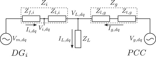
FIGURE 1. Equivalent model of parallel converters.
In steady state, a synchronous machine (SM) without pole saliency can be represented by its Thevenin equivalent, i.e., a voltage source with a series inductance Kundur et al. (1994). The equivalent AC voltage source amplitude is controlled by the DC field generated by the exciter, while frequency follows the swing equation or rotational equation of motion Eq. 6 Zhang et al. (2019). In Eq. 6
The power converter is normally a voltage-source converter (VSC), and it can therefore also be seen by its Thevenin equivalent circuit, which is similar to the SM (a voltage source with a series inductance). The inductance in the VSC is added to filter the current harmonics produced by the semi-conductor switching and thus also reduces the harmonics distortion introduced in the grid. The VSC voltage amplitude and frequency are both controlled by the converter modulation scheme (conventionally a sinusoidal PWM). There are therefore no constraints in the frequency rate of change imposed by the VSC hardware (it is an inertialess system). To introduce inertia and mimic the SG behavior, the VSC control loops must integrate the swing equation and reactive power droop (as in the SG case). The control loop adds inertia virtually but allows the manipulation of the virtual system in ways that cannot be accomplished in an SG, e.g., dynamically change the inertia of the system as suggested in Saxena et al. (2020). There are no rotating parts in the VSC hence, active power is supplied by the energy stored in the DC bus capacitance and interconnected sources.
In the scope of modern low voltage island microgrids, the intrinsic behavior of traditional power systems is not necessarily observed. The power converters interface with all sorts of sources (including rotational ones), and synchronous machines are therefore not directly connected to the grid. In this case, the active and reactive power sharing should be addressed considering the line impedance, converter dynamics, and the respective control loops.
2.1 Steady State Analysis of Parallel Sources
To understand the impact of load changes in the voltage and currents flowing in the local grid, Figure 1 is considered. In the Figure, a converter operating in grid-feeding (
Assuming that
The current flowing in the
During load transients significantly faster than converter current control bandwidth, converter modulation voltage
Taking into account previous analysis and considering n converters connected at
1. To share the load power it is necessary to know the PCC current;
2. Converter PLL does not allow us to track power angle change since each converter is synchronized with
3. Since load voltage is equally sensed by each converter, information about how many converters are connected would be required for proper load sharing.
To overcome the described issues, droop control is included in each converter control loop considering resistive line impedance, i.e.,
3 Grid-Forming and Grid-Support Operation Modes
Addressing the problems discussed in previous sections, we present a power-sharing control strategy based on both droop and AC bus signaling. The strategy consists of a converter operating as grid-forming responsible for grid generation and n slave converters that participate in the grid stability (operating in grid-support). The method resembles the master-slave approach, where a single unit generates references to the slave units. Though in this case there are no communications evolved and instead droop curves are designed to transmit the microgrid power needs, i.e., through AC bus signaling.
The grid-forming converter generates the microgrid voltage based on internal references (
3.1 Grid-forming Converter
The grid-forming converter is presented in Figure 2, where reference voltage and current are measured at filter output (grid side). The modulation voltage
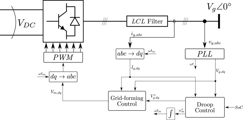
FIGURE 2. Simplified scheme of the Grid-forming converter.
The Grid-forming controller mode of operation is based on typical workbench power supplies, and the respective block diagram is presented in Figure 3, where it can be noticed that the control scheme is based on three main blocks. The forward gain
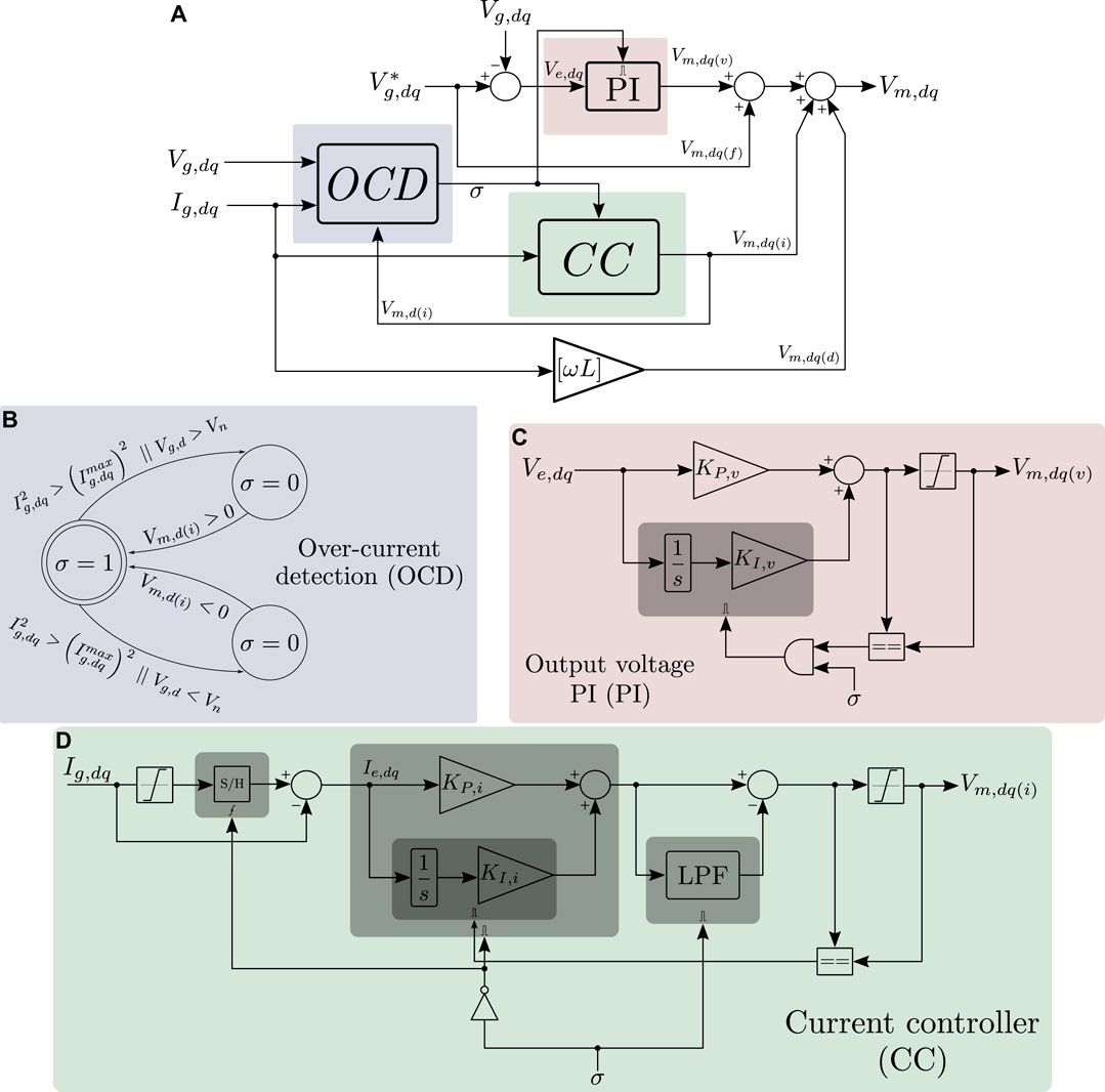
FIGURE 3. Grid-forming voltage and current control block diagram with over-current detection and regulator. (A) complete control loop, (B) over current detection state machine, (C) output voltage PI, and (D) current control loop.
The reference voltage
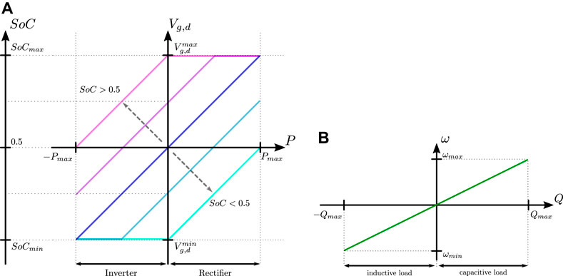
FIGURE 4. Representation of the grid-forming converter droop curves. (A) is the
The presented droop curves generate the AC bus signaling of the grid-forming converter. For a given
3.2 Grid-Support Converters
The grid-support converters considered in this work are bi-directional power sources that interface an energy storage system (e.g., electric vehicle on-board converter). The converter control scheme is illustrated in Figure 5. The control architecture consists of an inner current control loop based on the VOC Eq. 15 whose current references are obtained directly from the computation of power references (16).
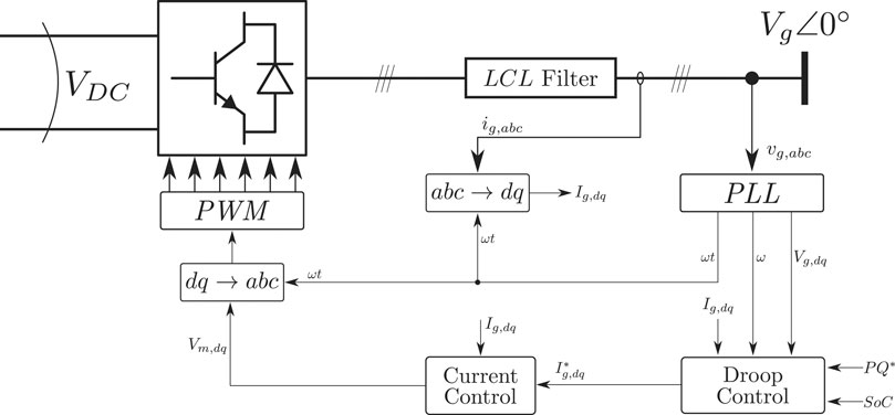
FIGURE 5. Simplified scheme of Grid-support converter.
The droop curves are similar to the grid-forming converter for a null external active power set-point as shown in Figure 6A. The droops are inverted, and converter power references are thus adjusted accordingly with the measured output voltage and frequency. As discussed before, the grid-forming converter thus lowers the microgrid voltage when its supplied power is increased. Such behavior signals the grid-support converters to increase their output power and consequently share the load power demand. The same logic is applied to the frequency and reactive power. Since active power curves are similar it should become obvious that for two units with the same
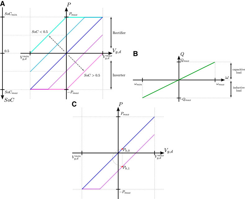
FIGURE 6. Representation of the grid-support converter droop curves. (A) is the
When the unit’s power set-point is externally changed in grid-supporting mode, the droop curve is shifted accordingly. The adjustment is equivalent to a change in the
There are two characteristics to be highlighted when considering the grid-forming converter operating with
(1) Converter power sharing is proportional to the available energy and power rating;
(2) The system tends toward battery energy balancing among the connected units, and as long as some units have available energy, system blackout or re-connection with the main grid is prevented.
4 Results and Discussion
This section presents the relevant results obtained through a numerical simulation and experimental prototype alongside with the respective discussion.
4.1 Simulation Results
The previously described methods were initially implemented through co-simulation with Matlab (Simulink) and Ansys (Simplorer). For the sake of simplicity, a converter switching model was replaced by controllable voltage sources, i.e., generated modulation voltages directly control a voltage source instead of being compared with a carrier and generate the respective PWMs. All units are three-phase converters operating in the synchronous reference frame with ratings as shown in Table 1. Furthermore, phase synchronization is achieved through a FFDSOGI-PLL Hoepfner et al. (2019) and the output filter is a
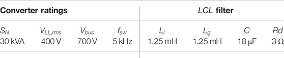
TABLE 1. Converters ratings and
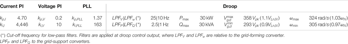
TABLE 2. converters controllers gains.
The considered testbed consists of three independent battery inverters with similar characteristics as described before. The converter ′
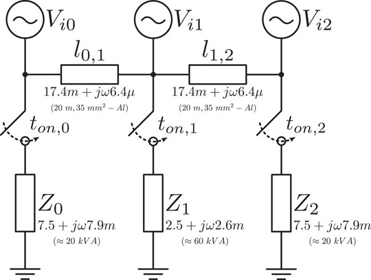
FIGURE 7. Island mode test bed.

TABLE 3. Power sharing test conditions.
Exceptionally for test 3 and 4, we adopted a model based only on the droop curves characteristic, the respective low pass filters and an additional low pass filter to replace the PLL dynamics (ω and
The results obtained for the test conditions described in Table 3 are shown in Figures 8–10.
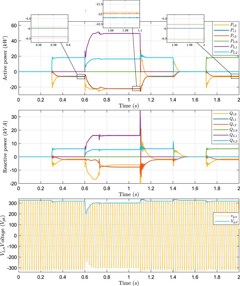
FIGURE 8. Test one simulation results. Active power, reactive power, and AC voltage of reference phase.
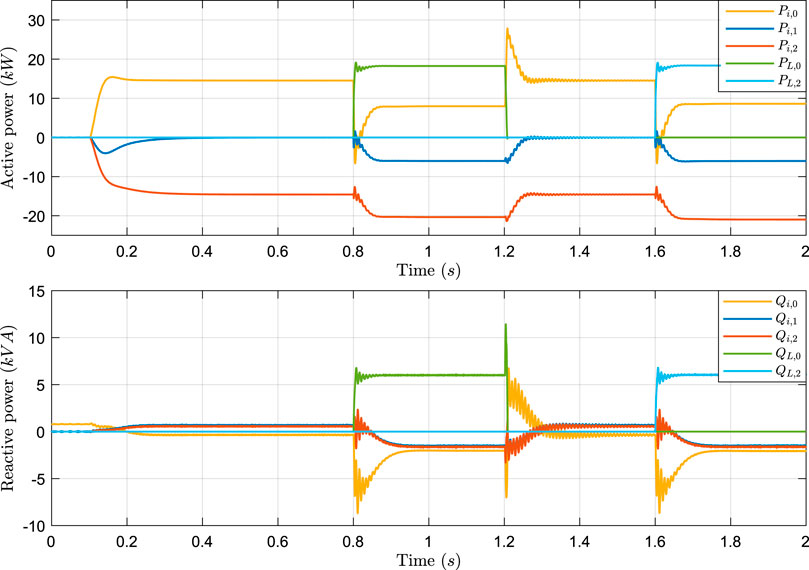
FIGURE 9. Test two simulation results. Active and reactive power. The
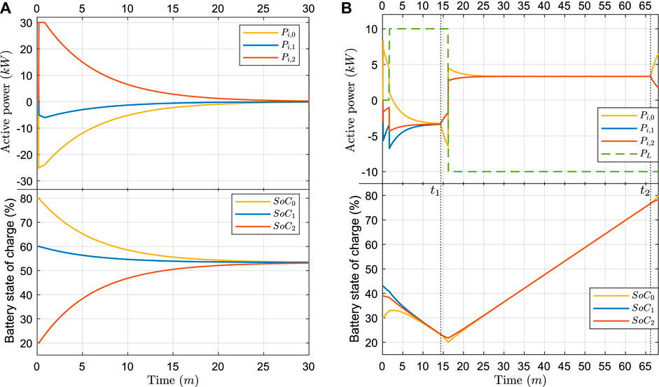
FIGURE 10. Active power and storage system
In 8, we show the active and reactive power of each converter and load. In the same Figure, we also show the reference phase AC voltage and synchronous voltage at the grid-forming converter (
In the Figure, it is possible to verify the fast response of the master converter during load change at
Figure 9 represents the power sharing when each converter unit presents a different
In test three of Figure 10A, we apply a condition with no load. There is therefore only the connection between the converters. As it can be seen by the proposed droop strategy, the droop will generate individual power references that tend to balance the different unit’s battery
In Figure 10B it is presented the results for test 4. In this test it can be noticed that the
The results obtained for the different tests allows to conclude that the grid forming converter would preferably be associated with the unit that presents higher energy storage availability. Additionally, it has to present enough power to fulfill the worst case load demand, which suggests some knowledge of the microgrid loads.
4.2 Experimental Results
The experimental setup consists of a downscale of the previous testbed of Figure 7, where only two units are used and the line impedance between them can be neglected. The experimental testbed can thus be considered a single node system. Additionally, there are no actual batteries in the system, and
In the Figure 11A it is presented the steady state voltage and currents of reference phase “a” with the
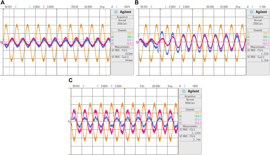
FIGURE 11. Steady-state condition. Line-neutral voltage at reference phase (yellow), reference phase current of grid-forming converter (blue), and reference phase current of grid-support converter (magenta). (A) initial steady state, (B) resistive load change with
Figure 12A presents the over-current protection results, which were obtained during an induction motor startup. The grid-forming maximum current was set at
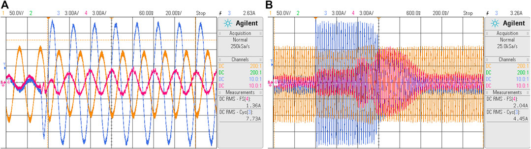
FIGURE 12. Transient during heavy load change-induction motor startup. Line-neutral voltage at reference phase (yellow), reference phase current of grid-forming converter (blue), and reference phase current of grid-support converter (magenta). (A) initial transient, and (B) total transient.
5 Conclusion
In this work, we present a new method that ensures proper power sharing and balancing between local loads and parallel converters in microgrids operating in island mode. The method also adds system inertia, which allows for seamless fulfillment of load power demands. The presented adaptive droop changes the active power droop gain accordingly with the battery
The proposed system can be applied in charging stations with renewable energy resources and storage systems, allowing for islanding without compromising the vehicle charging. Additionally, the method can be also implemented in a vehicle-to-grid approach, allowing multiple cars to generate a local grid in off-grid areas. Another example is the application in a vehicle-to-vehicle charging, where several vehicles may share the available energy and balance their batteries
Future works should extend the method to handle unbalanced phases by implementing a virtual impedance to the zero and negative sequence as proposed in Najafi et al. (2018). Furthermore, the grid-forming method should be improved during an over-current detection operation to allow the continuous operation of the droop control of the grid-support converters. As an extension of the current work, the authors also suggest further study of the
Data Availability Statement
The original contributions presented in the study are included in the article/Supplementary Material, further inquiries can be directed to the corresponding author.
Author Contributions
All authors have made a substantial, direct, and intellectual contribution to the work and approved it for publication.
Conflict of Interest
The authors declare that the research was conducted in the absence of any commercial or financial relationships that could be construed as a potential conflict of interest.
Supplementary Material
The Supplementary Material for this article can be found online at: https://www.frontiersin.org/articles/10.3389/fenrg.2020.609218/full#supplementary-material.
References
Burmester, D., Rayudu, R., Seah, W., and Akinyele, D. (2017). A review of nanogrid topologies and technologies. Renew. Sustain. Energy Rev. 67, 760–775. doi:10.1016/j.rser.2016.09.073
De Brabandere, K., Bolsens, B., Van den Keybus, J., Woyte, A., Driesen, J., Belmans, R., et al. (2007). “A voltage and frequency droop control method for parallel inverters,” in 2004 IEEE 35th Annual Power Electronics Specialists Conference IEEE Cat. No.04CH37551, Aachen, Germany, June 20–25, 2004 (IEEE) 4, 2501–2507. doi:10.1109/PESC.2004.1355222
D’Arco, S., and Suul, J. A. (2014). Equivalence of virtual synchronous machines and frequency-droops for converter-based MicroGrids. IEEE Transactions on Smart Grid. 5, 394–395. doi:10.1109/TSG.2013.2288000
Gu, Y., Li, W., and He, X. (2015). Frequency-coordinating virtual impedance for autonomous power management of DC microgrid. IEEE Trans. Power Electron. 30, 2328–2337. doi:10.1109/TPEL.2014.2325856
Gu, Y., Xiang, X., Li, W., and He, X. (2014). Mode-adaptive decentralized control for renewable DC microgrid with enhanced reliability and flexibility. IEEE Trans. Power Electron. 29, 5072–5080. doi:10.1109/TPEL.2013.2294204
Han, H., Hou, X., Yang, J., Wu, J., Su, M., and Guerrero, J. M. (2016). Review of power sharing control strategies for islanding operation of AC microgrids. IEEE Transactions on Smart Grid. 7, 200–215. doi:10.1109/TSG.2015.2434849
Hoepfner, B., Vick, R., and Magdeburg, O.-V.-G.-U. (2019). “Symmetrical components detection with FFDSOGI-PLL under distorted grid conditions,” in 2019 international conference on smart energy systems and technologies (SEST), Porto, Portugal, September 11, 2019 (IEEE) 2, 1–6
Jayalath, S., and Hanif, M. (2017). Generalized LCL-filter design algorithm for grid-connected voltage-source inverter. IEEE Trans. Ind. Electron. 64, 1905–1915. doi:10.1109/TIE.2016.2619660
Kundur, P., Balu, N. J., and Lauby, M. G. (1994). Power system stability and control., Vol. 7. New York, NY: McGraw-Hill
Ma, Y., Cao, W., Yang, L., Wang, F. F., and Tolbert, L. M. (2017). Virtual synchronous generator control of full converter wind turbines with short-term energy storage. IEEE Trans. Ind. Electron. 64, 8821–8831. doi:10.1109/TIE.2017.2694347
Moradi, M. H., Eskandari, M., and Hosseinian, S. M. (2016). Cooperative control strategy of energy storage systems and micro sources for stabilizing microgrids in different operation modes. Int. J. Electr. Power Energy Syst. 78, 390–400. doi:10.1016/j.ijepes.2015.12.002
Najafi, F., Hamzeh, M., and Fripp, M. (2018). Unbalanced current sharing control in islanded low voltage microgrids. Energies. 11, 2776. doi:10.3390/en11102776
Ramezani, M., and Li, S. (2018). “Simple and effective synchronization technique for synchronous generator emulating VSCs,” in IEEE Power and Energy Society General Meeting, Atlanta, GA, August 5–9, 2018 (IEEE) doi:10.1109/PESGM.2018.8586161
Renjit, A. A., Guo, F., and Sharma, R. (2016). “An analytical framework to design a Dynamic Frequency Control scheme for microgrids using energy storage,” in 2016 IEEE applied power electronics conference and exposition (APEC), Long Beach, CA, March 24, 2016 (IEEE). doi:10.1109/APEC.2016.7468093
Rocabert, J., Luna, A., Blaabjerg, F., and Rodríguez, P. (2012). Control of power converters in AC microgrids. IEEE Trans. Power Electron. 27, 4734–4749. doi:10.1109/TPEL.2012.2199334
Rokrok, E., Shafie-khah, M., and Catalão, J. P. (2018). Review of primary voltage and frequency control methods for inverter-based islanded microgrids with distributed generation. Renew. Sustain. Energy Rev. 82, 3225–3235. doi:10.1016/j.rser.2017.10.022
Said-Romdhane, M., Naouar, M., Belkhodja, I., and Monmasson, E. (2017). An improved LCL filter design in order to ensure stability without damping and despite large grid impedance variations. Energies. 10, 336. doi:10.3390/en10030336
Saxena, P., Singh, N., and Pandey, A. K. (2020). Enhancing the dynamic performance of microgrid using derivative controlled solar and energy storage based virtual inertia system. Journal of Energy Storage. 31, 101613. doi:10.1016/j.est.2020.101613
Sun, X., Hao, Y., Wu, Q., Guo, X., and Wang, B. (2017). A multifunctional and wireless droop control for distributed energy storage units in islanded AC microgrid applications. IEEE Trans. Power Electron. 32, 736–751. doi:10.1109/TPEL.2016.2531379
Tayab, U. B., Roslan, M. A. B., Hwai, L. J., and Kashif, M. (2017). A review of droop control techniques for microgrid. Renew. Sustain. Energy Rev. 76, 717–727. doi:10.1016/j.rser.2017.03.028
Urtasun, A., Sanchis, P., and Marroyo, L. (2015). State-of-charge-based droop control for stand-alone AC supply systems with distributed energy storage. Energy Convers. Manag. 106, 709–720. doi:10.1016/j.enconman.2015.10.010
Wu, T., Liu, Z., Liu, J., Wang, S., and You, Z. (2016). A unified virtual power decoupling method for droop-controlled parallel inverters in microgrids. IEEE Trans. Power Electron. 31, 5587–5603. doi:10.1109/TPEL.2015.2497972
Zhang, H., Zhang, R., Sun, K., and Feng, W. (2019). Performance improvement strategy for parallel-operated virtual synchronous generators in microgrids. Journal of Power Electronics. 19, 580–590. doi:10.6113/JPE.2019.19.2.580
Zhang, Y. (2017). Battery energy storage operation with adaptive droop control. In 2017 IEEE Conference on Control Technology and Applications (CCTA) (IEEE), 2017-Janua, 793–798. doi:10.1109/CCTA.2017.8062557
Zhong, Q.-C. (2016). Virtual Synchronous Machines: a unified interface for grid integration. IEEE Power Electronics Magazine. 3, 18–27. doi:10.1109/MPEL.2016.2614906
Keywords: microgrid, island, parallel converters, power sharing, droop control, Battery, bus signaling
Citation: Pinto J, Carvalho A and Morais V (2021) Power Sharing in Island Microgrids. Front. Energy Res. 8:609218. doi: 10.3389/fenrg.2020.609218
Received: 22 September 2020; Accepted: 23 November 2020;
Published: 15 January 2021.
Edited by:
Gabriele Grandi, University of Bologna, ItalyReviewed by:
Lieven Vandevelde, Ghent University, BelgiumFrancesco Lo Franco, University of Bologna, Italy
Copyright © 2021 Pinto, Carvalho and Morais. This is an open-access article distributed under the terms of the Creative Commons Attribution License (CC BY). The use, distribution or reproduction in other forums is permitted, provided the original author(s) and the copyright owner(s) are credited and that the original publication in this journal is cited, in accordance with accepted academic practice. No use, distribution or reproduction is permitted which does not comply with these terms.
*Correspondence: Jorge Pinto, jorgemsp@fe.up.pt