Self-loading microfluidic platform with ultra-thin nanoporous membrane for organ-on-chip by wafer-level processing
 Bo Tang1,2*†
  Sebastian Bendas3,2† Victor Krajka1,2
  Tobias May4 Anke Moritz1
  Iordania Constantinou1,2
  Stephan Reichl3,2
  Andreas Dietzel1,2*
- 1Institute of Microtechnology, Technische Universität Brauschweig, Brauschweig, Germany
- 2Center of Pharmaceutical Engineering (PVZ), Technische Universität Braunschweig, Braunschweig, Germany
- 3Institute of Pharmaceutical Technology and Biopharmaceutics, Technische Universität Braunschweig, Braunschweig, Germany
- 4InSCREENeX GmbH, Braunschweig, Germany
Embedded porous membranes are a key element of various organ-on-chip systems. The widely used commercial polymer membranes impose limits with regard to chip integration and thinness. We report a microfluidic chip platform with the key element of a monolithically integrated, ultra-thin (700 nm) nanoporous membrane made of ultra-low-stress (
1 Introduction
Since organ-on-chip systems (OOCs) were introduced, embedded porous membranes have been established as one of their critical elements (Casillo et al., 2017; Pasman et al., 2018; Shanti et al., 2018; Richardson et al., 2020; Wu et al., 2020). Important functions of biological membranes include cell enclosure and the separation of different functional tissues, forming a selective barrier for the transportation of molecular cargo based on size or physicochemical charactersistics (Subczynski et al., 2017). Unlike biological membranes, micro or nanofabricated porous membranes filter components or cells only by a well-defined porosity. In OOCs, porous membranes are commonly introduced as a scaffold for 3D cell co-cultivation or as a carrier of endothelial and parenchymal cells. These membranes which may be part of Transwell® inserts, can define the tissue-tissue interface for mimicking the through-transport of fluids, nutrients, immune cells, drugs or even pathogenic factors (Banks, 2016; Casillo et al., 2017; Beissner et al., 2018; Mattern et al., 2018; Pasman et al., 2018; Richardson et al., 2020; Wu et al., 2020). Stretchable polymeric membranes even enable the application of dynamic mechanical loads to the in vitro tissue as can occur in the in vivo microenvironment (Huh et al., 2011, 2010; Gonçalves et al., 2022). However, the widely used porous polymer membranes have a typical thickness of 10–40 μm, which imposes limits on the reduction of the pore diameter as long as the depth-to-diameter ratio is to be kept low so as not to restrict transport through the pores and to allow communication between cells on both sides. Soft lithographic production of porous membranes usually uses a SU8 or Si mold master with structured micropillars. With this approach, the final micropore dimensions are influenced by the sequence of casting, curing, and release processes (Huh et al., 2012, 2011, 2010; Miranda et al., 2021; Gonçalves et al., 2022). A PDMS porous membrane needs to be released from the master substrate by using sacrificial layers or surface silanization, which is typically not very stable so that mass production is difficult. Track etched polycarbonate (PC) or polyester (PET) membranes are commercially available, cheap, and widely used in cell cultivation. However, they exhibit a stochastic distribution of pores that can overlap forming unwanted larger openings (Casillo et al., 2017; Bolze et al., 2021; Schneider et al., 2021). Another serious disadvantage is, that prefabricated polymer membranes cannot be integrated into wafer-level manufacturing in the clean room, where perfectly reproducible chips can be produced in high quantities. Instead, they require assembly processes that are too imprecise and difficult to automate for mass production. The alternative of using thin porous SixNy membranes for cell cultivation has been discussed earlier (Harris and Shuler, 2003). They can be fabricated as part of a monolithic MEMS device on wafer level. To structure SixNy membranes with sub-micron patterns by UV-lithography demands a high-resolution mask, which has to be brought in tight contact with the spin-coated photoresist, which is typically associated with problems of particle contamination. Moreover, with binary masks the resolution remains limited (Harriott, 2001).
Nanopatterning with EUV-projection lithography as used in microelectronics is an alternative but requires extremely expensive equipment and specially made masks (Totzeck et al., 2007). Focused ion beam (FIB) patterning can produce nanopores directly in the membrane material but due to re-deposition effects the pore walls are typically tapered. Moreover, the process is slow and the ion beam charges a dielectric membrane, inducing stress, and sporadic breakage (Peltonen et al., 2016). Electron beam lithography (EBL) is typically also slow when a high porous density is required (Górzny et al., 2019). Nano-imprint lithography (NIL) shows outstanding performance in nanopore fabrication, but is still limited by the low process flexibility and high cost of imprint masks (Traub et al., 2016; Sosa-Hernández et al., 2018; Li et al., 2022; Tahir et al., 2022). Digital laser exposure provides an alternative to mask-based lithography but only with the use of femtosecond laser pulses even nanoscale patterns can be created in various photoresists by two-photon-polymerization (2pp) (Koch et al., 2006; Jee et al., 2021). Structures below 100 nm made by 2pp have already been demonstrated (Koch et al., 2006; Ding et al., 2018; van der Velden et al., 2020). Each pulse creates an ellipsoidal voxel by two-photon-absorption within the photoresist. Fast scanners have been developed to provide high-throughput exposure. Despite these technological opportunities, an increasing number of publications on microfluidic cell culture systems still describe works on devices built by low cost and easy to implement fabrication methods. Often, polycarbonate (PC), PDMS or other polymer-based plastics are used as materials to construct microfluidic environments. PDMS provides biocompatibility and gas permeability, which in some cases can be considered an advantage for cell culture because there is no need to introduce extra oxygen supply. However, the porous nature of PDMS contributes to molecule absorption, which can be a severe disadvantage for drug screening applications or when gas concentration control is required (Miranda et al., 2021; Schneider et al., 2021). In contrast, the use of glass, silicon and other inorganic materials that are typically used in MEMS can exclude such effects. In order to establish not only a microfluidic chip but a fully functional test system to be used in a conventional lab incubator, gravimetric pumping has been demonstrated (Wang and Shuler, 2018; Lee et al., 2019). However, it has to be proven that not only adequate media delivery, but also a shear stress that mimics the physiological situation is provided. In vivo, endothelial cells can withstand a shear stress caused by blood flow in a wide range. For example, in blood-brain-barrier tissue, the stress could reach 10–14 dyne/cm2, but is below 1 dyne/cm2 in large veins (Papaioannou and Stefanadis, 2005; Wang and Shuler, 2018; Lee et al., 2019). Previous reports suggest that an ultra-thin nanoporous membrane can not only be more similar to the thickness of the in vivo vascular basement membrane (about 300 nm) but also promotes the cell-cell interactions (Carter et al., 2017; Casillo et al., 2017). In this work, a Si/glass based organ-on-chip system including an ultra-thin nanoporous SixNy membrane shall be presented, which can mimic a blood vessel as sketched in Figure 1. Since the concept is of general nature, other tissues would also be implementable. The objectives of this work include not only the design of a chip system and its manufacturing using a scalable wafer-level process suitable for mass production in foundries for dramatically reducing the cost of individual chips, but also the proof of chip functionality in a gravity driven pumping environment enabling very simple execution of experiments within common cell incubator cabinets. Moreover, highly reproducible capillary force driven cell injection shall replace pressure driven injection. Computational fluid dynamic (CFD) simulation shall be applied to prove homogeneous flow shear stress distributed over the cells on the membrane. Overall, a new platform shall promote broad use of organ on microfabricated chip technologies.
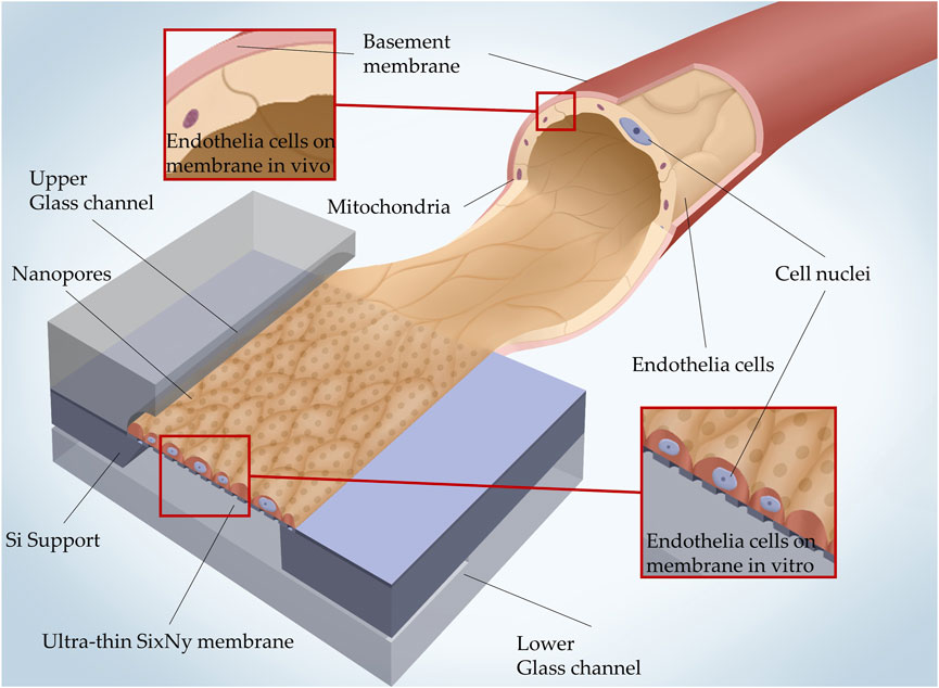
FIGURE 1. 3D illustration of how the in vivo microcapillary vessel structure is mimicked in a glass/Si microfluidic MEMS with a SixNy nanoporous membrane. In vivo the basement membrane separates the endothelial cells and pericytes. The SixNy nanoporous membrane separates the upper and lower glass channels and acts as a scaffold on which endothelial cells can settle.
2 Materials and methods
2.1 Fabrication of SixNy nanoporous membranes
Photoresist AZ MRI 701 14cp is spin coated at 6,000 rmp/min on 4 inch silicon wafers [orientation (100), thickness 380 µm] coated with 700 nm ultra-low stress SixNy (
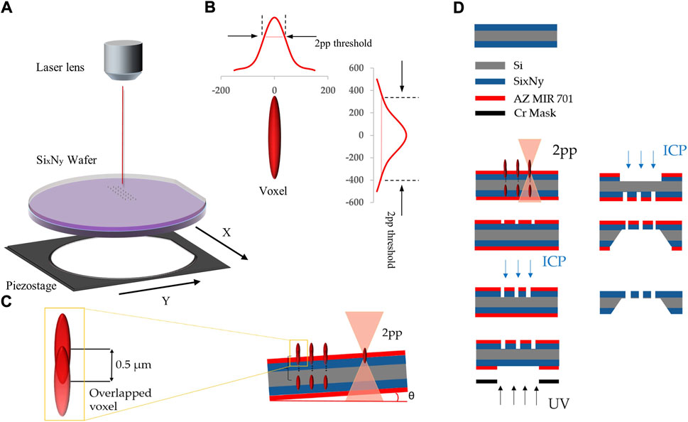
FIGURE 2. (A) Schematic of the 2pp exposure setup using a focused femtosecond-laser-beam and a piezostage with a position accuracy
Even though one voxel can expose the entire layer thickness of the resist, to avoid uncertainties in the substrate tilt (Figure 2C) the use of multiple partially overlapping voxels at incrementing z-heights is required to avoid that the resist at some pore positions is not exposed throughout the layer thickness. It was determined that 14 voxels with a z-increment of 0.5 µm were sufficient to compensate uncertainties in interface position and substrate tilt that practically occurred. Since absorption is non-linear, the energies within a single voxel are relevant and cannot be summed up with overlapping voxels for reaching the energetic threshold for two photon absorption. Therefore, only part of a second voxel overlapping with a first one contributes to resist exposure (Fischer and Wegener, 2013).
In Figure 2D, the wafer-level fabrication of the nanoporous membrane starting with the silicon wafer that is coated on both sides with ultra-low stress SixNy is sketched. After exposure to the nanopore pattern by 2pp, the resist was developed. Subsequently, ICP plasma dry etching (Oxford Instruments Cobra 300 ICP power 140 W, SF6 129 sccm) was used to create nanopores in the SixNy. A membrane window (3 × 3 mm) is defined by standard UV lithography on the opposite wafer side. This opening is transferred from the photoresist into the SixNy layer by ICP dry etching with the same process used for the nanopore etching before. The membrane is released by KOH wet etching of silicon, leaving a rigid frame around the ultra-thin nanoporous membrane. Alternatively, one can eliminate the need for the resist development step if the laser pulse energy exceeded the ablation threshold for the resist.
2.2 Design and fabrication of microfluidic chip
The schematic drawing in Figure 3A illustrates the basic construction of the chip comprising two glass layers between which the silicon layer with the nanoporous membranes is sandwiched. In order to enable a very even inflow and outflow, which is hardly possible via vertical vias, the channels are led up to the chip edges. This results in lateral inlets and outlets which extend over the entire cross section of the channels. Fluidic channels of 100 µm depth were wet etched by HF (70% diluted with DI water) into a borosilicate wafer (700 µm Borofloat® substrates from Schott AG, Mainz, Germany) to form blood vessel mimicking structures. Endothelial cells were cultivated onto the nanoporous membranes (Figure 3B).
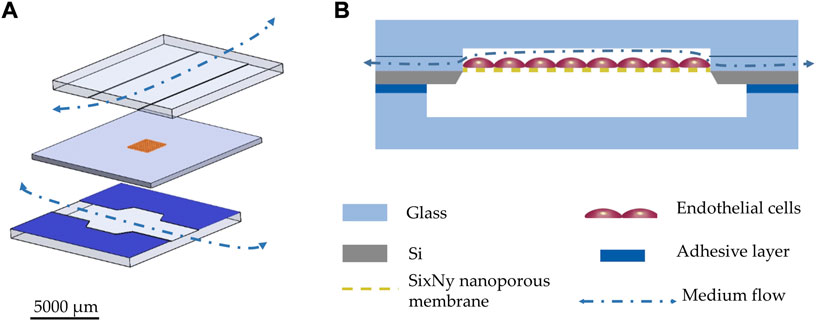
FIGURE 3. (A) 3D explosion drawing of the OOC system: the top and bottom glass layers are comprising wet chemically etched 100 µm deep channels; the middle layer comprises a silicon frame, which is holding the SixNy membrane with dry etched nanopores. The bottom glass layer is coated with a silicone rubber film as adhesive sealing layer (ARcare® 90106NB). (B) schematic cross-section of the chip.
The endothelial compartments were closed by anodic bonding (Figure 4) of the glass wafer to the SixNy surface (at 380°C, 900 V in vacuum). The same wet etching process was used to form the lower channels of 200 µm depth in another glass wafer. Both wafers were diced (DAD 320 Dicing Saw from DISCO Corporation) to form the two halves of single chips (12 mm × 12 mm). Both halves were combined during the cultivation procedure by a thin adhesive layer (ARcare® 90106NB). At the membrane area 420 µm deep channels are thereby created. With adhesive bonding of the two halves, even after initial cell cultivation the user shall be able to easily reopen the system for further analysis. The nanopores shall allow passage of molecules from the endothelial upper compartment through the membrane into the lower compartment. When overgrown with endothelial cells, porous membranes can mimic the biological basement membrane.
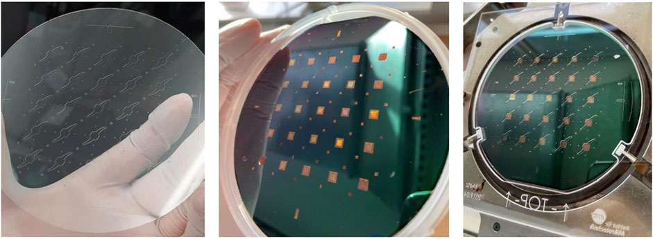
FIGURE 4. Left: structured 4-inch glass wafer representing the upper glass layer. Middle: structured silicon wafer with the SixNy membrane. Right: structured silicon aligned with the 0.7 mm thick glass wafer comprising the wet etched upper compartments, placed in the tool for anodic bonding. With one wafer 5 × 5 chip systems can be produced. The picture shows a wafer carrying a preliminary chip design slightly deviating from the one discussed in this paper.
2.3 3D printed holder with gravity driven pumping environment
A chip holder was 3D printed (using Keyence AGILISTA-3200W with AR-M2 transparent print material). The holder comprises a gravity driven pumping environment to provide a bi-directional dynamic flow in the chips microchannels. The holder together with a sketch illustrating the gravity driven pumping is shown in Figure 5.
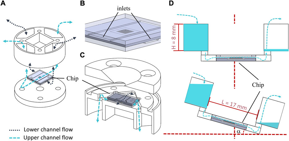
FIGURE 5. (A) Explosion drawing of the chip holder with gravity driven fluid supply system where the dashed lines indicate how the open media reservoirs are connected to the chip compartments. (B) Zoomed 3D drawing of the OOC system with large inlets on the edge. (C) Explosion drawing providing view from the bottom into the half-cut holder with chip. The bi-directional flow stream is sketched with dashed-lines. (D) Schematic illustration of the gravity driven pumping with rocking angle α facilitated by the holder with critical geometries L and H.
With the initial reservoir fill level H, the maximum pressure drop over the chip and resulting flow rates and shear stresses in the channel can be easily controlled with the tilt angle α as expressed by Eqs 1–3. The pressure drop in dependence of α is given as:
Where L is the distance between the two opposite reservoirs (Figure 5D). ρ is the density of the fluid and g is the gravity constant. With the dimensions of the upper flow chamber (h = 100 μm, l = 1,200 μm and w = 5,000 μm), the volumetric flow rate Q and the resulting shear stress τ acting on the membrane in a rectangular channel can be calculated as:
Where μ is the dynamic viscosity of the cell medium at the cultivation temperature of 37°C. The situation of flow through the upper compartment, resulting shear stress, and flow velocity distributions occurring at the SixNy surface were also studied in detail using computational fluid dynamics (CFD) simulation in Ansys fluent® (2019). The initial situation assumes that one reservoir was filled with H = 8 mm and the opposite reservoir was empty. Maximal shear stress values were obtained for the maximum tilt angle (25°) attainable with the lab-rocky (MIMETAS OrganoFlow®).
2.4 Cell cultivation
In all experiments a murine microvascular endothelial cell line (CI-muMEC from InSCREENeX) was used, that was established using the CI-SCREEN technology (Lipps et al., 2018). Static cultivation was performed in gelatin coated cell culture flasks with muMEC medium (InSCREENeX) according to the manufacturer’s instructions. The medium was changed three times a week. Cultivation was performed in a CO2 incubator (5% CO2, 100% rh). In the cell loading phase, cells can be introduced into the chamber using a pipette injector or directly thereby avoiding unusable sample or solution that remains in the delivery inlet tube.
For studies performed using the microfluidic chip system developed, a protocol for decontamination, seeding and cultivation was designed, which is shown schematically in Figure 6. First, the upper chip half made of glass and the SixNy membrane are tightly bonded to the 3D printed upper holder part, using an adhesive layer (ARcare® 90106NB). The lower glass chip half was bonded to the lower holder in the same manner. All components were decontaminated in ethanol (70% v/v) for at least 1 h (Step 1.). Subsequently, the upper and lower parts of the system were separately placed in single wells. For the upper part, the glass side must point downwards; as the glass chip part of the reservoir must open upwards. After drying, the SixNy chip half was filled with a 0.5% gelatin solution in PBS for at least 30 min at 37°C. This was followed by seeding muMEC cells via the channel of the SixNy chip. For this purpose, 500,000 cells were resuspended in 25 µL medium. The strong capillary effect in the hydrophilic microchannel and the large inlets at the chip edge help to uniformly distribute the solution on the nanoporous membrane, which is critical for cell seeding. The initial distribution of cell solution will directly influence the uniformity of the tissue growing on the membrane (Step 2). In order to ensure a successful cell adhesion, the 6-well-plate was placed in a CO2 incubator for at least 3 h and checked under the microscope. We pre-cultivated muMEC cells under static environment for 1 day until a monolayer was formed (Step 3). After pre-cultivation, the upper part and the lower part of the holder were assembled thereby closing the chip system. The assembled holder still fits into a single well of a standard 6-well-plate, whereby possible infection and evaporating of the culture medium is prevented (Step 4). After adding enough medium into the fluidic tank of the holder, the well plate was placed on a programmable rocking platform in the CO2 incubator for long-term dynamic cultivation (Step 5). Routine microscopic examinations were performed within the 6-well-plate. For immunohistochemical studies, the SixNy chip half can be easily removed from the holder (Step 6).
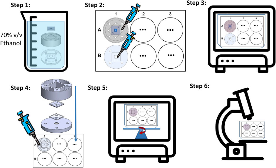
FIGURE 6. Schematic illustration of the on-chip cell cultivation protocol steps. Step 1: System decontamination including holder and chip. Step 2: Cell seeding with pipette through the holder reservoir into closed upper chip compartment (A) and cell seeding directly into the open cavity of the glass layer forming the lower chip compartment (B). Step3: Pre-cultivation in the incubator. Step 4: System assembly with closure of the lower chip compartment. Step 5: Long-term cultivation under bi-directional gravity driven flow induced by the rocking platform. Step 6: Investigation of in the chip grown tissue under a light microscope.
3 Results
3.1 Multi-scale fabrication of organ-on-chip platform
As shown in Figures 7A,B, hole diameters in the developed 2pp resist of around 600 nm were obtained with laser powers of about 15 mW but even smaller diameters of below 400 nm were obtained. Diameters down to 100 nm should be possible (Koch et al., 2006; Ding et al., 2018; van der Velden et al., 2020) but are not necessary in the specific application in order to prevent the passage of cells. By controlling the pores spacing and diameter, a wide porosity range of the membrane can be defined to accommodate different cell types and physiological models. The resulting porosities (2%–20%) and pore sizes (300 nm–1,020 nm) are in the range of what has been found as porosities in liver sinusoidal endothelial cells (LSECs) (Zapotoczny et al., 2020). At laser powers above 37 mW plasma plumes become visible during the laser process, which means that the ablation threshold is exceeded. The ablated holes show rough edges probably caused by redeposition of ablated material onto the resist surface. By plasma etching, this roughness is also transferred to the SixNy surface in the vicinity of the pore whereas membranes structured with developed resist appear to have smooth surfaces at the pore vicinity (Figure 7C). The nanopores appears always completely open (Figure 7D).
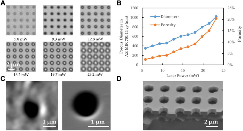
FIGURE 7. (A) Electron microscopy images with nanopore patterns in the developed photoresist in dependence of laser power. (B) The corresponding diameters and porosities in the resulting nanoporous membrane as obtained from electron micrographs. (C) SEM images of single nanopores in SixNy as obtained by ICP plasma etching and subsequent resist stripping. Left: At a laser power of 37.7 mW the photoresist was directly ablated. Right: At a lower laser power of 23.2 mW, the resist was only locally polymerized and developed afterwards. (D) SEM image of cleaved membrane (tilted by 45°).
Smooth pore edges are preferred because roughness can lead to stress concentration and potentially reduce membrane stability. Moreover, rough edges could negatively influence the cell growth. Therefore, only the 2pp method was applied in fabrication of complete OOCs. Figure 8 shows all components of the complete OOC platform including the chip holder parts with medium reservoirs and the micro and nanostructured upper and lower chip halves. Details of the nanostructured membrane are shown with an electron microscope zoom at the nanoporous SixNy membrane showing pores of 650 nm in diameter. The assembly of chip halves and chip holder parts led to a leak-tight fluidic connection of the upper and lower microchannels to the reservoirs filled with culture medium.
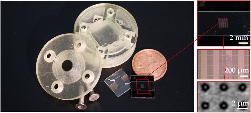
FIGURE 8. The finished OOC with a large inlet on the edge and zoomed in (electron) microscopic images showing the nanoporous SixNy membrane with a pore size of 650 nm.
3.2 Gravity driven flow
Using CFD simulation, the micro flow in the endothelial compartment and the corresponding wall shear stress at the membrane surface was investigated (Figure 9) under the assumption that all medium liquid was still in only one reservoir filled to a level of H = 8 mm and that any liquid transport through the membranes can be neglected. For α = 15°an average flow velocity of 0.032 m/s and a wall shear stress at the membrane surface of 9.6 dyne/cm2 were obtained (figure a/b upper). For α = 0°an average flow velocity of 0.021 m/s and a wall shear stress of 6.4 dyne/cm2 were obtained (Figures 9A,B lower). These values are low enough to allow good adherence and growth of cells on the nanoporous membrane.
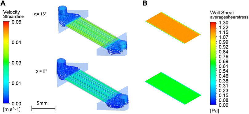
FIGURE 9. Velocity profiles (streamlines shown are at different channel heights) in the upper channel compartment (A) and shear stress distributions at the surface of the nanoporous SixNy membrane (B) as obtained with CFD simulations assuming gravity at α = 15°and α = 0°.
For comparison, for α = 15°, a flow velocity of 0.037 m/s and shear stress of 9.8 dyne/cm2 at the surface of the SixNy are obtained using Eqs 1–3. It shows that the flow resistances of the channels in the chip holder which are taken into account in the simulation only, have a negligible effect. It is important that with the unique fluidic side in-coupling, flow velocities and the shear stresses are extremely uniform across the membrane area. Thereby, cells can evenly settle during chip colonizing, be exposed to culture medium nutrients, and experience same shear stresses everywhere. Gravity driven flow is not typical for microfluidics because the flow rate keeps changing. Nevertheless, gravity perfusion has certain advantages in the field of organ-on-a-chip. It is easier to operate in typical cell cultivation laboratories, it is cost effective and it requires no extra tubing (Wang and Shuler, 2018; Lee et al., 2019). Moreover, blood flows are also pulsating.
3.3 Cell culture
The established protocol including decontamination and the static pre-cultivation of the system shows the desired homogeneous colonization of the membrane (Figures 10A–C) without typical problems of pressure driven injection into the chip with parabolic velocity profile, which were discussed recently. (Koch et al., 2022). The hydrophilic nature of glass (contact angel
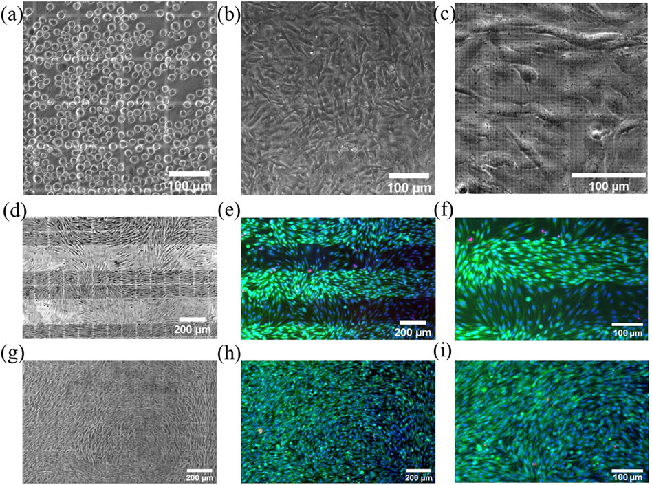
FIGURE 10. Microscopic views into the closed chip showing muMEC cells on top of gelatin coated SixNy nanoporous membrane. (A) Directly after self-loading seeding and (B) after 1 day of pre-cultivation. Supported by strong capillary forces in the microchannel and the large inlets from the chip edge, muMEC cells are equally distributed and can grow as a confluent monolayer. (C) Zoom-in reveals the nanopore areas in the SixNy membrane and more details of the cells. Bright field images taken after pre-cultivation and 3 days of dynamic chip cultivation (D,G) together with corresponding fluorescence images with live/dead staining (green/red) and blue cell nucleus staining (E,F,H,I). Shown is the growth on continuously nanoporous membranes (D–F) and on membranes with only nanoporous sections (G–I). The zoom-ins (F,I) show the formation of a confluent cell layers only on nanoporous areas.
For the latter, columnar sections with nanopores were spaced 200 µm. Cells were cultivated in a CO2 incubator on the rocking platform with a maximum angle of inclination of 15° and an angular velocity 5° per second, maximum shear stress of about 10 dyne/cm2 at membrane surface in upper channel while the lower channel was filled with static medium. After 3 days, the chips were investigated under the microscope and then reopened for live/death staining, using calcein-AM (0.005 mg/ml) to recognize live cells by the green color and propidium iodide to label dead cells (0.02 mg/ml) showing in red color (Figures 10E–I). These cultivation experiments were carried out three times with good reproducibility but only images of one experiment is shown in Figure 10. Only very few dead cells were detected on both membrane configurations, demonstrating the suitability of these systems. While cells on the fully porous membrane showed very uniform growth (Figures 10G–I), cells on the partly porous membrane showed patterned growth (Figures 10D–F).
When their nuclei were stained with Hoechst 33,342 (0.02 mg/ml) cells were found to be in greater numbers on the porous areas (Figure 11). With the shear force generated by the dynamic flow, the muMECs were polarized in shape (Figures 10D–I). A single experiment also confirmed confluent tissue after 5 days of cultivation (see Supplementary Figure S1).
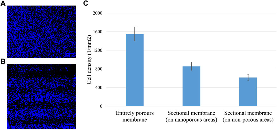
FIGURE 11. Stained nuclei for cell density evaluation on continuous (A) and patterned (B) nanopore distributions. Cell densities (C) obtained with the cell counter finder software Fiji (IMAGEJ, National Institutes of Health, Bethesda, MD) show highest values for the membranes with continuous porosity. Data are expressed as mean values ±standard deviation.
4 Discussion
We successfully developed an organ-on-chip platform with an ultra-thin nanoporous SixNy membrane realized by wafer-level MEMS microfabrication processes suitable for up-scaling. The digital lithography by 2pp proved to be a flexible method for defining the nanopores. For future production of large quantities of identical chips a high-resolution mask-based lithography can be used as less flexible but more easily scalable alternative. The chip holder with pumpless dynamic flow control is compatible with standard 6-well-plate and offers easy implementation in laboratories equipped with common incubation chambers. The unique fluid side inlet ensures, that all cells on the membrane are exposed to identical flow velocities and resulting shear stresses. Moreover, due to the hydrophilic nature of SixNy and glass the self-loading seeding is controlled by capillary forces which leads to a bottom-up control, that makes the seeding procedure not only very homogeneous but also less dependent on the operator.
As proof of concept, we successfully pre -cultured muMEC under static conditions for one-day and under dynamic flow conditions for 3 days as confirmed also by live/death staining. A confluent and more dense growth of cells on SixNy membranes was observed in the presence of nanopores. This may be explained by a better medium supply to the cells through the lower channel in these areas and the reduced cell-substrate contact area promoting cell-cell interactions. Already at the boarders of nanoporous areas however, cells have less interaction with cells on nonporous area and therefore the mean cell-cell interaction is reduced when porous areas are in neighborhood of nonporous areas. Similar observations have been reported in the literatures (Lee et al., 2004; Narayan and Venkatraman, 2008; Carter et al., 2017; Casillo et al., 2017). These penomena will be investigated in future research also with tight-junction assays (cell-cell interactions) and focal adhesion markers (cell-substrate). It is obvious that the nanoporous SixNy membranes are an ideal material for cell cultivation not only because they are tissue-friendly, but also because they can be made extremely thin and allow communication through the pores. In future, other types of cells and prolonged cell co-cultivation will be evaluated in this platform. By placing the two channels crosswise, we can ensure that one channel is exposed to shear stress and the other is not. The channel with the shear stress is excellent for building an endothelial barrier. In turn, the other non-flow channel is dedicated to cells not exposed to flow under physiological conditions, e.g., astrocytes, neurons, hepatocytes, pericytes, etc., This can be exploited to mimic organ-like interfaces and barriers of the human body, such as BBB/Neurovascular unit, liver, and vessels.
In further research, the optical observation could also be replaced or augmented by impedance measurements using integrated micro-electrodes which could be realized within the MEMS fabrication route.
Data availability statement
The original contributions presented in the study are included in the article/Supplementary Material, further inquiries can be directed to the corresponding authors.
Author contributions
Conceptualization: BT, AD, and SR; Methodology: BT and SB; Validation: BT, SB, and VK; Investigation: BT and SR; Resources, AD and SR; Writing—original draft preparation: BT, SB, SR, VK, and AD; Writing—review and editing: BT, AD, SR, IC; Supervision: AD, SR, and IC. All authors have read and agreed to the published version of the manuscript.
Acknowledgments
We would like to thank TM and his team from InSCREENeX for their support and free use of the muMEC cell line for our experiments. We acknowledge support by the Open Access Publication Funds of Technische Universität Braunschweig.
Conflict of interest
TM was employed by InSCREENeX GmbH, Germany.
The remaining authors declare that the research was conducted in the absence of any commercial or financial relationships that could be construed as a potential conflict of interest.
Publisher’s note
All claims expressed in this article are solely those of the authors and do not necessarily represent those of their affiliated organizations, or those of the publisher, the editors and the reviewers. Any product that may be evaluated in this article, or claim that may be made by its manufacturer, is not guaranteed or endorsed by the publisher.
Supplementary material
The Supplementary Material for this article can be found online at: https://www.frontiersin.org/articles/10.3389/fsens.2022.974895/full#supplementary-material
References
Banks, W. A. (2016). From blood-brain barrier to blood-brain interface: New opportunities for cns drug delivery. Nat. Rev. Drug Discov. 15, 275–292. doi:10.1038/nrd.2015.21
Beissner, N., Mattern, K., Dietzel, A., and Reichl, S. (2018). Dynamites - a dynamic cell culture platform for in vitro drug testing part 2 - ocular dynamites for drug absorption studies of the anterior eye. Eur. J. Pharm. Biopharm. 126, 166–176. doi:10.1016/j.ejpb.2017.03.021
Bolze, H., Riewe, J., Bunjes, H., Dietzel, A., and Burg, T. P. (2021). Protective filtration for microfluidic nanoparticle precipitation for pharmaceutical applications. Chem. Eng. Technol. 44, 457–464. doi:10.1002/ceat.202000475
Carter, R. N., Casillo, S. M., Mazzocchi, A. R., DesOrmeaux, J.-P. S., Roussie, J. A., and Gaborski, T. R. (2017). Ultrathin transparent membranes for cellular barrier and co-culture models. Biofabrication 9, 015019. doi:10.1088/1758-5090/aa5ba7
Casillo, S. M., Peredo, A. P., Perry, S. J., Chung, H. H., and Gaborski, T. R. (2017). Membrane pore spacing can modulate endothelial cell-substrate and cell-cell interactions. ACS Biomater. Sci. Eng. 3, 243–248. doi:10.1021/acsbiomaterials.7b00055
Ding, H., Zhang, Q., Gu, Z., and Gu, M. (2018). 3d computer-aided nanoprinting for solid-state nanopores. Nanoscale Horiz. 3, 312–316. doi:10.1039/c8nh00006a
Fischer, J., and Wegener, M. (2013). Three-dimensional optical laser lithography beyond the diffraction limit. Laser. Photonics Rev. 7, 22–44. doi:10.1002/lpor.201100046
Gonçalves, I. M., Rodrigues, R. O., Moita, A. S., Hori, T., Kaji, H., Lima, R. A., et al. (2022). Recent trends of biomaterials and biosensors for organ-on-chip platforms. Bioprinting 26, e00202. doi:10.1016/j.bprint.2022.e00202
Górzny, M., Opara, N. L., Guzenko, V. A., Cadarso, V. J., Schift, H., Li, X. D., et al. (2019). Microfabricated silicon chip as lipid membrane sample holder for serial protein crystallography. Micro. Nano Eng. 3, 31–36. doi:10.1016/j.mne.2019.03.002
Harris, S. G., and Shuler, M. L. (2003). Growth of endothelial cells on microfabricated silicon nitride membranes for anin vitro model of the blood-brain barrier. Biotechnol. Bioprocess Eng. 8, 246–251. doi:10.1007/BF02942273
Huh, D., Hamilton, G. A., and Ingber, D. E. (2011). From 3d cell culture to organs-on-chips. Trends Cell. Biol. 21, 745–754. doi:10.1016/j.tcb.2011.09.005
Huh, D., Leslie, D. C., Matthews, B. D., Fraser, J. P., Jurek, S., Hamilton, G. A., et al. (2012). A human disease model of drug toxicity-induced pulmonary edema in a lung-on-a-chip microdevice. Sci. Transl. Med. 4, 159ra147. 159ra147. doi:10.1126/scitranslmed.3004249
Huh, D., Matthews, B. D., Mammoto, A., Montoya-Zavala, M., Hsin, H. Y., and Ingber, D. E. (2010). Reconstituting organ-level lung functions on a chip. Sci. (New York, N.Y.) 328, 1662–1668. doi:10.1126/science.1188302
Jee, H., Park, M.-J., Jeon, K., Jeong, C., and Lee, J. (2021). Combining interference lithography and two-photon lithography for fabricating large-area photonic crystal structures with controlled defects. Appl. Sci. 11, 6559. doi:10.3390/app11146559
KINO Scientific Instrument,Inc (2020). Contact angle of water on smooth surfaces and wettability. Available at:http://www.uskino.com/articleshow_113.html. Accessed June 01, 2022.
Koch, E. V., Ledwig, V., Bendas, S., Reichl, S., and Dietzel, A. (2022). Tissue barrier-on-chip: A technology for reproducible practice in drug testing. Pharmaceutics 14, 1451. doi:10.3390/pharmaceutics14071451
Koch, J., Fadeeva, E., Engelbrecht, M., Ruffert, C., Gatzen, H. H., Ostendorf, A., et al. (2006). Maskless nonlinear lithography with femtosecond laser pulses. Appl. Phys. A 82, 23–26. doi:10.1007/s00339-005-3418-7
Lee, D. W., Choi, N., and Sung, J. H. (2019). A microfluidic chip with gravity-induced unidirectional flow for perfusion cell culture. Biotechnol. Prog. 35, e2701. doi:10.1002/btpr.2701
Lee, S. J., Choi, J. S., Park, K. S., Khang, G., Lee, Y. M., and Lee, H. B. (2004). Response of mg63 osteoblast-like cells onto polycarbonate membrane surfaces with different micropore sizes. Biomaterials 25, 4699–4707. doi:10.1016/j.biomaterials.2003.11.034
Li, Y., Su, J., Xu, J., Yang, L., and Yang, G. (2022). Optical and laser-induced damage characterization of porous structural silicon oxide film with hexagonal period by nanoimprint lithography. Coatings 12, 351. doi:10.3390/coatings12030351
Lipps, C., Klein, F., Wahlicht, T., Seiffert, V., Butueva, M., Zauers, J., et al. (2018). Expansion of functional personalized cells with specific transgene combinations. Nat. Commun. 9, 994. doi:10.1038/s41467-018-03408-4
Mattern, K., Beißner, N., Reichl, S., and Dietzel, A. (2018). Dynamites - a dynamic cell culture platform for in vitro drug testing part 1 - engineering of microfluidic system and technical simulations. Eur. J. Pharm. Biopharm. 126, 159–165. doi:10.1016/j.ejpb.2017.04.022
Miranda, I., Souza, A., Sousa, P., Ribeiro, J., Castanheira, E. M. S., Lima, R., et al. (2021). Properties and applications of pdms for biomedical engineering: A review. J. Funct. Biomater. 13, 2. doi:10.3390/jfb13010002
Narayan, D., and Venkatraman, S. S. (2008). Effect of pore size and interpore distance on endothelial cell growth on polymers. J. Biomed. Mat. Res. A 87, 710–718. doi:10.1002/jbm.a.31749
Papaioannou, T. G., and Stefanadis, C. (2005). Vascular wall shear stress: Basic principles and methods. Hellenic J. Cardiol. HJC = Hellenike kardiologike epitheorese 46, 9
Pasman, T., Grijpma, D., Stamatialis, D., and Poot, A. (2018). Flat and microstructured polymeric membranes in organs-on-chips. J. R. Soc. Interface 15, 20180351. doi:10.1098/rsif.2018.0351
Peltonen, A., Nguyen, H. Q., Muhonen, J. T., and Pekola, J. P. (2016). Milling a silicon nitride membrane by focused ion beam. J. Vac. Sci. Technol. B, Nanotechnol. Microelectron. Mater. Process. Meas. and Phenom. 34, 062201. doi:10.1116/1.4963895
Richardson, L., Kim, S., Menon, R., and Han, A. (2020). Organ-on-chip technology: The future of feto-maternal interface research? Front. Physiol. 11, 715. doi:10.3389/fphys.2020.00715
Schneider, S., Gruner, D., Richter, A., and Loskill, P. (2021). Membrane integration into pdms-free microfluidic platforms for organ-on-chip and analytical chemistry applications. Lab. Chip 21, 1866–1885. doi:10.1039/d1lc00188d
Shanti, A., Teo, J., and Stefanini, C. (2018). In vitro immune organs-on-chip for drug development: A review. Pharmaceutics 10, 278. doi:10.3390/pharmaceutics10040278
Sosa-Hernández, J. E., Villalba-Rodríguez, A. M., Romero-Castillo, K. D., Aguilar-Aguila-Isaías, M. A., García-Reyes, I. E., Hernández-Antonio, A., et al. (2018). Organs-on-a-chip module: A review from the development and applications perspective. Micromachines 9, 536. doi:10.3390/mi9100536
Subczynski, W. K., Pasenkiewicz-Gierula, M., Widomska, J., Mainali, L., and Raguz, M. (2017). High cholesterol/low cholesterol: Effects in biological membranes: A review. Cell. biochem. Biophys. 75, 369–385. doi:10.1007/s12013-017-0792-7
Tahir, U., Kim, J. I., Javeed, S., Khaliq, A., Kim, J.-H., Kim, D.-I., et al. (2022). Process optimization for manufacturing functional nanosurfaces by roll-to-roll nanoimprint lithography. Nanomater. (Basel, Switz. 12, 480. doi:10.3390/nano12030480
Totzeck, M., Ulrich, W., Göhnermeier, A., and Kaiser, W. (2007). Pushing deep ultraviolet lithography to its limits. Nat. Photonics 1, 629–631. doi:10.1038/nphoton.2007.218
Traub, M. C., Longsine, W., and van Truskett, N. (2016). Advances in nanoimprint lithography. Annu. Rev. Chem. Biomol. Eng. 7, 583–604. doi:10.1146/annurev-chembioeng-080615-034635
van der Velden, G., Fan, D., and Staufer, U. (2020). Fabrication of a microfluidic device by using two-photon lithography on a positive photoresist. Micro. Nano Eng. 7, 100054. doi:10.1016/j.mne.2020.100054
Wang, Y. I., and Shuler, M. L. (2018). Unichip enables long-term recirculating unidirectional perfusion with gravity-driven flow for microphysiological systems. Lab. Chip 18, 2563–2574. doi:10.1039/c8lc00394g
Wu, Q., Liu, J., Wang, X., Feng, L., Wu, J., Zhu, X., et al. (2020). Organ-on-a-chip: Recent breakthroughs and future prospects. Bio. med. Eng. OnLine 19, 9. doi:10.1186/s12938-020-0752-0
Keywords: organ-on-chip, SixNy ultra-thin membrane, nanopores, MEMS, two-photon polymerization (2PP), gravity driven pumping, microvascular endothelial cells, capillary flow
Citation: Tang B, Bendas S, Krajka V, May T, Moritz A, Constantinou I, Reichl S and Dietzel A (2022) Self-loading microfluidic platform with ultra-thin nanoporous membrane for organ-on-chip by wafer-level processing. Front. Sens. 3:974895. doi: 10.3389/fsens.2022.974895
Received: 21 June 2022; Accepted: 27 September 2022;
Published: 12 October 2022.
Edited by:
Martina Viefhues, Bielefeld University, GermanyReviewed by:
Xueye Chen, Liaoning University of Technology, ChinaAmid Shakeri, McMaster University, Canada
Yiqiang Fan, Beijing University of Chemical Technology, China
Copyright © 2022 Tang, Bendas, Krajka, May, Moritz, Constantinou, Reichl and Dietzel. This is an open-access article distributed under the terms of the Creative Commons Attribution License (CC BY). The use, distribution or reproduction in other forums is permitted, provided the original author(s) and the copyright owner(s) are credited and that the original publication in this journal is cited, in accordance with accepted academic practice. No use, distribution or reproduction is permitted which does not comply with these terms.
*Correspondence: Bo Tang, b.tang@tu-braunschweig.de; Andreas Dietzel, a.dietzel@tu-braunschweig.de
†These authors have contributed equally to this work and share first authorship