Article

Comparison of a Novel Organic-Fluid Thermofluidic Heat Converter and an Organic Rankine Cycle Heat Engine †

by
Christoph J.W. Kirmse
,
Oyeniyi A. Oyewunmi
,
Andrew J. Haslam
and
Christos N. Markides
*
Clean Energy Processes (CEP) Laboratory, Department of Chemical Engineering, Imperial College London, South Kensington Campus, London SW7 2AZ, UK
*
Author to whom correspondence should be addressed.
This paper is an extended version of our paper published in Proceedings of the 3rd International Seminar on ORC Power Systems, Brussels, Belgium, 12–14 October 2015.
Submission received: 15 March 2016 / Revised: 10 May 2016 / Accepted: 26 May 2016 / Published: 23 June 2016

Abstract

:
The Up-THERM heat converter is an unsteady, two-phase thermofluidic oscillator that employs an organic working fluid, which is currently being considered as a prime-mover in small- to medium-scale combined heat and power (CHP) applications. In this paper, the Up-THERM heat converter is compared to a basic (sub-critical, non-regenerative) organic Rankine cycle (ORC) heat engine with respect to their power outputs, thermal efficiencies and exergy efficiencies, as well as their capital and specific costs. The study focuses on a pre-specified Up-THERM design in a selected application, a heat-source temperature range from 210 °C to 500 °C and five different working fluids (three n-alkanes and two refrigerants). A modeling methodology is developed that allows the above thermo-economic performance indicators to be estimated for the two power-generation systems. For the chosen applications, the power output of the ORC engine is generally higher than that of the Up-THERM heat converter. However, the capital costs of the Up-THERM heat converter are lower than those of the ORC engine. Although the specific costs (£/kW) of the ORC engine are lower than those of the Up-THERM converter at low heat-source temperatures, the two systems become progressively comparable at higher temperatures, with the Up-THERM heat converter attaining a considerably lower specific cost at the highest heat-source temperatures considered.

Graphical Abstract

1. Introduction

Ensuring long-term energy and environmental security by reducing the current rates of consumption of finite fossil-fuel reserves and the release of related emissions to the environment have been increasingly desirable goals in recent years. Specifically, the interest in the utilization of sustainable energy resources such as geothermal and solar heat, which are abundantly available, is attracting increasing attention, as is the recovery and utilization of low- and medium-grade (i.e., temperature) waste heat, significant quantities of which are being rejected in the industrial, transport and residential sectors [1,2]. These goals can be met to an extent by collecting or recovering thermal energy from the above mentioned sources and converting this heat to useful work such as electricity, shaft work, or pumping (hydraulic) work. Because of the lower heat-source temperatures involved (relative to conventional power generation), the thermal efficiency of any system used for this purpose is expected to be inherently low. Therefore, cost is also of primary importance in the deployment of relevant solutions.
Thermofluidic oscillators are one particular class of thermodynamic heat converters that can utilize lower-grade external heat sources cost-effectively. This class of systems includes single-phase thermofluidic oscillators such as Sondhauss tubes [3,4], standing-wave thermoacoustic engines [5], and the Fluidyne engine [6]. Alternatively, two-phase thermofluidic oscillators are also being considered, such as the "Non-Inertive-Feedback Thermofluidic Engine" (NIFTE) [7,8,9,10] and the Up-THERM heat converter, which comprises a single reciprocating solid piston. In particular, the NIFTE has been shown to be capable of operating across temperature differences between a heat source and sink as low as 30 °C [11]. One important characteristic of thermofluidic oscillators is their reliance (by-design) on far fewer moving parts and dynamic seals during operation, and their simpler construction featuring more basic components. This allows more affordable materials and manufacturing techniques to be used, leading to lower capital costs but also longer maintenance cycles and lower operating costs than conventional power-generation systems.
The Up-THERM heat converter was proposed by Encontech B.V. [12,13] and further developed under the EU FP7 project Up-THERM [14]. The device is described in detail in Kirmse et al. [15,16,17] and Oyewunmi et al. [18], and a similar concept referred to as the “Evaporative Reciprocating-Piston Engine” (ERPE) is reported in Taleb et al. [
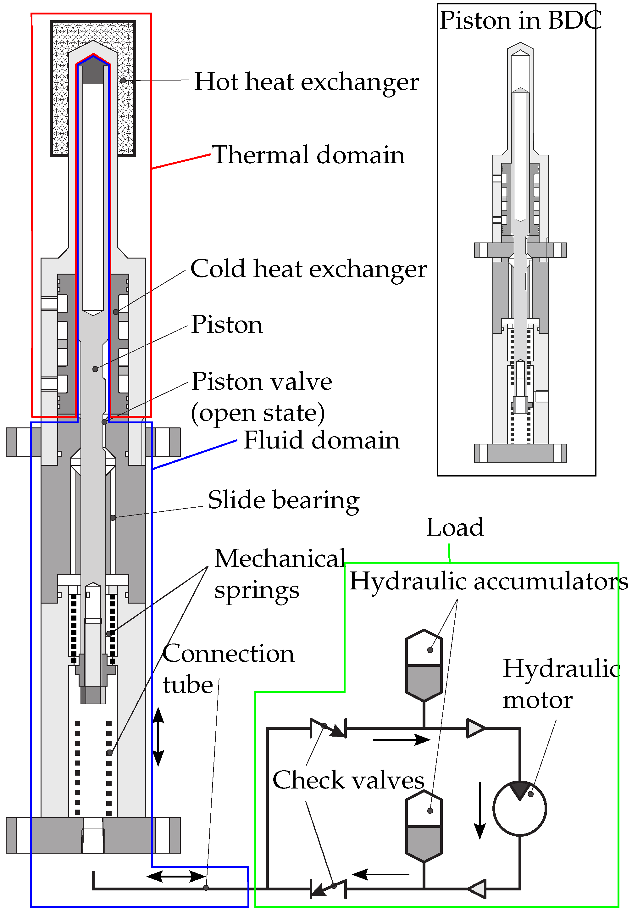
19]. Briefly, a constant temperature difference applied and maintained, by an external heat source and sink, between the hot and cold parts of the Up-THERM heat converter gives rise to periodic alternating evaporation and condensation of the working fluid as this oscillates within the device thereby undergoing an unsteady thermodynamic cycle. This leads to unsteady oscillations of pressure, temperature, and volume within the engine and, consequently, the reciprocating motion of liquid within the device and the reciprocating vertical motion of a solid piston. By transforming the oscillatory movement of the liquid into unidirectional flow through the use of check valves and hydraulic accumulators, power can be extracted by a hydraulic motor.
The organic Rankine cycle (ORC) is also a technology that is capable of converting lower-grade (external) heat into useful work. It is a more commercially mature technology compared to the novel concept of the Up-THERM heat converter, and a significant effort has been placed in the technical development and improvement of this technology, especially in the field of waste heat recovery [20,21,22,23,24,25,26,27]. In particular, ORC engines promise relatively high efficiencies at low temperatures and power outputs and form a natural benchmark for the technical and economic assessment of the Up-THERM heat converter.
In this paper, we compare the concept of the Up-THERM heat converter, based on a pre-specified Up-THERM (geometric) design in a selected application, to the ORC engine technology with a view towards employing the Up-THERM heat converter as a combined heat and power (CHP), or cogeneration, prime-mover. To this end, we perform a thermodynamic and economic comparison of the two technologies, recovering heat from heat sources in the temperature range from 210 °C to 500 °C. Three n-alkanes (n-pentane, n-hexane, and n-heptane) and two refrigerants (R134a and R227ea) are investigated as working fluids over the heat-source temperature range of interest.
The methods used for the modeling of the Up-THERM heat converter and the equivalent sub-critical, non-regenerative ORC engine are described in Section 2. Moreover, in Section 2 we give a brief explanation of the calculation of the capital costs of both systems. This is followed by an examination of the following thermodynamic performance indicators of both engines: power output, exergy efficiency, and thermal efficiency. It may be expected that the ORC engine will outperform the Up-THERM heat converter purely in terms of these thermodynamic performance indicators. We proceed to investigate the economic performance of the two engines. In particular, we consider the capital costs and specific costs per unit power. Due to its simple design, fewer and more basic components, it can also be expected that the Up-THERM heat converter will have lower capital costs than its ORC counterpart, which has a technically more complex construction, as mentioned above. On the other hand, the specific costs of the two systems and how these compare are of particular interest here, in the context of the future uptake and implementation of these technologies.

2. Materials and Methods

2.1. Up-THERM Engine Configuration and Operation

A schematic of the Up-THERM engine is shown in Figure 1. The engine is completely filled with liquid working fluid, except above the piston, where vapour working fluid fills a gas spring. The engine comprises two parts, the displacer cylinder and the load arrangement. These two parts are connected via the connection tube. The displacer cylinder represents the thermofluidic oscillator part of the engine. It consists of the hot heat-exchanger (HHX) and cold heat-exchanger (CHX), the solid piston that forms together with the inner wall of the displacer cylinder the piston valve, a slide bearing where piston and liquid working fluid are separated, and two mechanical springs that are fixed to the top and bottom of the lower part of the displacer cylinder and are loosely attached to the piston. The load arrangement contains two check valves, two hydraulic accumulators and the hydraulic motor.
Assuming a cycle to start with the piston in the top dead centre the vapour-liquid interface is in contact with the HHX, the piston valve is open and the top mechanical spring is fully compressed. Liquid working fluid evaporates, thereby increasing the pressure in the gas spring above the piston. This, together with the mechanical spring, forces the piston downwards and the piston valve closes preventing fluid from flowing from the chamber above the valve into the one below. Thus, the pressure in the upper chamber increases while the pressure in the lower chamber stays almost constant. Due to inertia the piston moves beyond its equilibrium position and the lower mechanical spring is compressed while the upper mechanical spring is fully relaxed. When the piston moves further down, the piston valve opens. The pressure difference between the upper and lower chambers is suddenly equalized and liquid working fluid flows downwards through the piston valve. The vapour-liquid interface is now in contact with the CHX. Working-fluid vapour condenses and reduces the pressure in the gas spring. The piston and vapour-liquid interface start moving upward until the piston valve closes again. Now only the piston moves upwards and a pressure difference is established between the upper and lower chamber, where the pressure in the upper chamber is lower than the pressure in the lower chamber. When the piston valve opens again this pressure difference gets suddenly equalized and working fluid flows from the lower into the upper chamber.

2.2. Up-THERM Model Development

The modelling methodology taken for the Up-THERM is an extension of previous approaches employed for the modeling of thermoacoustic and thermofluidic devices, starting from the earlier work of Ceperley [5], Huang and Chuang [28] and Backhaus and Swift [29,30]. In particular, due to its reliance on the phase change of the working fluid, the Up-THERM engine has some similarities to the NIFTE, models for which were first proposed by Smith [7,8,9] and later extended and improved by Markides and Smith [11] and Solanki et al. [31,32,33]. Furthermore, the work of Markides et al. [34] represented the first attempt to introduce a non-linear characteristic into the model of the NIFTE (specifically, a static temperature profile in the device’s heat exchangers); this approach is also undertaken in the model of the Up-THERM used in the present paper. Since the NIFTE modeling methodology has been validated against experimental data generated by a device prototype, it is regarded as an appropriate starting point for the modeling of the Up-THERM engine. The Up-THERM engine model is described in detail in Kirmse et al. [17]. Oyewunmi et al. [18] investigated the influence of different (especially organic) working fluids on the engine performance.
The Up-THERM model is split into thermal and fluid domains, with a model derived for each component in these domains. The dominant thermal or fluid process in each component is described by first-order spatially lumped, ordinary differential equations (ODEs). Electrical analogies are drawn such that thermal resistance and fluid drag are represented by resistors, liquid inertia by an inductor, and hydrostatic pressure difference and vapour compressibility by capacitors. The passive electrical components are interconnected in an electric circuit network in the same way as they are connected in the physical device. For the following components small fluctuations around the respective time-mean value are assumed, allowing for linearization: the piston including the fluid around it and the slide bearing; the liquid column in the displacer cylinder; the connection tube; the hydraulic accumulators; and the hydraulic motor. The piston valve in the displacer cylinder and the two check valves exhibit inherently non-linear behavior. The temperature profile in the heat exchanger walls is assumed to follow a hyperbolic tangent function, which has been validated experimentally in Kirmse et al. [17]. Hence, these three components are modeled non-linearly.

2.2.1. Thermal Domain

In the thermal domain, heat that is added to/removed from the cycle and converted into mechanical displacement ( p V ) work, gives rise to a fluctuating pressure oscillation and induces a reciprocating flow. The useful flow quantity of the exchanged heat is its associated entropy flow. The linearized entropy flow rate associated with the heat exchange is:
S ˙ = Q ˙ in T 0 = h A hx T 0 T hx ( y ( t ) ) - T wf
where S ˙ is the entropy flow rate due to heat transfer, T 0 is the (constant) equilibrium temperature half-way between the extreme hot (source) and cold (sink) temperatures in the heat exchangers, Q ˙ in is the rate at which heat is added to the cycle, h is the (constant) heat-transfer coefficient, A hx is the (constant) area over which phase-change heat transfer occurs, T hx ( y ( t ) ) is the temperature of the heat-exchanger wall that is in contact with the vapour-liquid interface and depends on its position, and T wf is the temperature of the working fluid. A detailed explanation of the heat-transfer process can be found in Solanki et al. [32] and Markides et al. [11]. The heat-transfer coefficient h can be calculated using the following correlation [35]:
h = h ref F p * F w F q
In Equation (2) h ref is a reference heat-transfer coefficient for a specific fluid, which is determined experimentally, and F i non-dimensional functions that are independent of the fluid. The reference heat-transfer coefficient for n-pentane is 3300 W / m 2 K , that for n-hexane is 3200 W / m 2 K , and that for n-heptane is 2900 W / m 2 K . The pressure factor F p * takes the dependence of h on the reduced pressure of the fluid into account. For the three n-alkanes used in this work the value of F p * varies between 1.6 and 14. The wall factor F w = F wm F wr is dependent on the properties of the heat-exchanger wall material and surface roughness of the heat-exchanger wall. For steel as the heat-exchanger material a wall material factor F wm of 0.61 is used. As no information relating to the surface roughness is available the surface roughness factor F wr is set to 1, as recommended in Reference [35]. The heat-input factor F q takes the dependence of the heat-transfer coefficient on the heat input Q in into the cycle into account, and its value varies in the range between 3.5 and 7.2. Thus, the value of the heat-transfer coefficient varies between 12,600 W / m 2 K and 170,000 W / m 2 K .
For the investigated refrigerants the values of h ref are 4200 W / m 2 K (R134a) and 4100 W / m 2 K (R227ea). Thus, the heat-transfer coefficients range between 71,000 W / m 2 K and 87,000 W / m 2 K .
As the heat-transfer coefficient is an input to the model, but the heat input an output of the model, an iterative approach is chosen to calculate h. Therein the heat input of the previous step is taken to calculate the heat-transfer process of the current step. Iterations are stopped when convergence is achieved. A detailed description of the calculation for the heat-transfer coefficient can be found in Kirmse et al. [17] and Oyewunmi et al. [18].
The non-linear profile of the heat-exchanger wall temperature can be described by [34]:
T hx y = α tanh β y
where α is the amplitude of the temperature in the heat-exchanger wall. The parameter β is related to the height of the heat exchanger where the temperature profile saturates, which is assumed to be at the maximum length of the heat exchanger. This temperature profile has been validated experimentally in Kirmse et al. [17] and thus is deemed suitable for the present paper. As can be seen in Equation (3), the temperature of the heat-exchanger wall is dependent on the position y of the vapour-liquid interface. A graphical representation of the temperature profile is shown in Figure 2.
As the remainder of the engine is described in the fluid domain, the thermal and fluid domain must be coupled. This can be achieved by using the following three coupling equations [11]:
S ˙ = ρ v s fg U th
T hx y t = d T d P sat P th ; T wf = d T d P sat P v
where ρ v is the density of the vapour working fluid, s fg the phase-change specific entropy and U th the volumetric flow rate. The rate of change of working-fluid temperature with pressure in the saturation region is denoted by d T d P sat , the thermal pressure by P th and the pressure in the displacer cylinder gas spring by P v .

2.2.2. Fluid Domain

In the fluid domain quasi-steady, laminar and fully developed flow is assumed, as the Reynolds and Wormersley numbers are sufficiently low. Viscous drag in the displacer cylinder, connection tube, and load arrangement are represented by a resistance:
R = 128 μ l π d 4
where μ is the dynamic (absolute) viscosity of the working fluid, l the length of the liquid column and d its diameter. Liquid inertia is represented by an inductance:
L = 4 ρ l l π d 2
where ρ l is the density of the liquid working fluid. The hydrostatic pressure of the liquid column in the displacer cylinder and the vapour compressibility in the hydraulic accumulators and displacer cylinder gas spring are represented by capacitances:
C d = π d 2 4 ρ l g ; C a = V 0 γ P 0 ; C v = V 0 + V v γ P 0 + P v
with g the gravitational acceleration, γ the heat-capacity ratio, V 0 and P 0 the equilibrium volume and pressure, and V v and P v the time-varying volume and pressure. For a detailed description of the resistances, inductances and capacitances see Kirmse et al. [17].
To model the piston and the surrounding fluid flow, a force balance is applied to the piston and the surrounding fluid (simplified Navier-Stokes). In the slide bearing underneath the piston valve, the piston and liquid are separated. While the piston slides through one channel, lubricated by a small amount of liquid, the bulk of the fluid flows through two separate channels. As the channels have a constant height, the hydrostatic pressure difference is constant and hence, is neglected. Thus, the electrical analogies for the piston, fluid, and slide bearing are:
R l , 1 = 128 c 2 l p μ π c 1 c 3 ; R l , 2 = 128 c 2 l p μ π c 1 c 1 2 c 2 d p 2 ; C l = π 2 c 1 c 1 c 2 d p 2 64 c 2 2 k ms ; L l = 64 c 2 2 m p π 2 c 1 c 1 2 c 2 d p 2 R p = 64 l p μ π d p 2 c 1 ; C p = π 2 d p 2 c 1 32 k ms c 2 ; L p = 32 m p c 2 π 2 d p 2 c 1 ; R b , p = 16 μ l b π 2 d p 3 δ ; L b , p = 4 ρ ss l b π d p 2 L b , l = 4 ρ l l b π d b 2 ; R b , l = 128 μ l b π d b , l 4
In Equation (9) l p is the length of the piston, d p its diameter, m p its mass, δ the size of the gap between the piston and the walls of the slide bearing, and ρ ss the density of stainless steel, the material of which the piston is made. The slide bearing has the length l b and d b , l denotes the diameter of the channels through which the fluid flows, k ms is the spring constant of the mechanical spring; c 1 , c 2 and c 3 are geometric constants, with c 1 = d c 2 d p 2 , c 2 = ln d c / d p , and c 3 = c 2 d c 2 + d p 2 c 1 .
Further to the linear descriptions of the piston, liquid column in the displacer cylinder, and connection tube, the inherently non-linear behavior of the piston valve, formed by the piston and the inner wall of the displacer cylinder, is described as a non-linear resistance using a Heaviside step function H { . } :
R pv = R min , pv + 1 2 R max , pv H P l , d ρ l g l pv + H P l , d + ρ l g l pv
where R min , pv and R max , pv are the minimum and maximum value of the resistance, respectively; P l , d the hydrostatic pressure difference across the liquid in the displacer cylinder, which represents the position of the piston; and l pv the height at which the valve opens or closes. Furthermore, a non-linear resistance is introduced that prevents the amplitudes of oscillation in the displacer cylinder from becoming longer than the displacer cylinder length:
R nl = R max , nl H P l , d ρ wf g l nl + H P l , d ρ wf g l nl
In Equation (11) R max , nl is the maximum value of the resistance and h nl the maximum amplitude. Due to the design of the engine this resistance is used for all heat-source temperatures and working fluids. It is desirable that the piston and the vapour-liquid interface oscillates along the entire length of the heat exchanger to use the maximum available area of the heat exchanger. When the piston hits the top or bottom of the displacer cylinder, it can be ensured that the amplitudes of oscillations are sufficiently large. This behavior has also been observed in the prototype testing.

2.2.3. Load

In the load arrangement a hydraulic motor is chosen to convert the energy of the fluid into shaft work. The hydraulic motor needs to be supplied with an (almost) constant unidirectional flow. Therefore, two check valves convert the oscillating fluid flow into an unidirectional flow. The check valves are described as a non-linear resistance:
R cv = R max , cv H { U }
where R max , cv is the maximum resistance when the valve is closed. The two hydraulic accumulators dampen the amplitudes of pressure and volumetric displacement. They are described linearly using Equation (8). The losses and inertia of the hydraulic motor are calculated using a torque balance on the motor. To calculate the power that can be extracted from the engine Ohm’s law is used. Thus, the resistance, inductance and power of the engine are:
R hm = 16 μ lub d sh 3 l sh π ϵ d 4 d hm 2 ; L hm = 8 m hm π d 4 ; W ˙ hm = R gen U hm 2
In the above equation the dynamic viscosity of the lubricant is described by μ lub ; the diameter and length of the shaft by d sh and l sh respectively; the gap between the shaft and motor by ϵ ; the diameters of the tube and motor by d and d hm respectively; the mass of the motor by m hm ; and the flow rate through the motor by U hm . The load resistance R gen is determined empirically to achieve the maximum power output of the engine.

2.3. Up-THERM Engine Model

The models of each component in the three domains are combined to form the dynamic Up-THERM engine model. As electrical analogies are used to represent the dominant thermal and fluid effects in each component, an electrical circuit diagram can be drawn to represent the entire device. This circuit is shown in Figure 3. The values for the resistances, inductances, and capacitances (or collectively, R, L, and C parameters) from Figure 3 are summarized in Table 1. Based on a given specification for the employment of an Up-THERM heat converter as a CHP prime-mover (suggested in the testing procedure of a prototype Up-THERM engine), the proposed physical dimensions of the Up-THERM heat converter along with the working-fluid properties are used to define all R L C model parameters. Since the values of some of the electrical components are dependent on the fluid properties, the values given in Table 1 are for n-pentane at a heat-source temperature of 210 °C.
The external heat source to the device is a stream of heat-transfer fluid (thermal oil), whose mass flow rate is set to 1 kg/s in accordance with the recommended flow rate proposed for the Up-THERM prototype testing. It is assumed that no phase change of the heat-transfer fluid takes place. The given heat-source temperatures correspond to the inlet temperature of the hot side into the hot heat-exchanger. The heat sink is a water stream with an inlet temperature of 10 °C.

2.4. Calculation of Thermodynamic Performance Indicators

Three performance indicators are used in the comparison. The first is the power output of the hydraulic motor:
W ˙ hm = R gen U hm d V hm
where V hm = U hm d t is the volume displaced in the hydraulic motor during one cycle. The second performance indicator is the exergy (second law) efficiency, which can be calculated as the ratio between the power output and the exergy input into the system:
η ex = W ˙ hm P th d V th
In the above equation W ˙ hm is the power output and P th d V th the exergy input into the cycle. The thermal pressure P th is the equivalent of the heat-source temperature in the fluid domain and the thermal volume equivalent to the entropy that is generated during heat addition in one cycle, see Equations (4) and (5). Hence, it can be regarded as T d S , which corresponds to an exergy. V th = U th d t is the entropy flow into the working fluid expressed in the fluid domain. The thermal efficiency as a third performance indicator relates the power output of the cycle to the heat input:
η th = W ˙ hm Q ˙ in
with W ˙ hm from Equation (14) and Q ˙ in from Equation (1).
The oscillation frequency F as a fourth performance indicator is unique to the Up-THERM engine in this comparison. It is calculated from the period T of one oscillation/cycle:
F = 1 T

2.5. Organic Rankine Cycle Model Development

In Figure 4 we provide a schematic of the sub-critical ORC engine that is modelled in this paper. As the Up-THERM heat converter has a simple design with no super-heating and no regeneration, this simple layout is chosen for the ORC engine used in the comparison in this work; a recuperator/regenerator would increase the cost and complexity of the ORC engine in comparison to the Up-THERM engine. Furthermore, it has been shown that super-heating of the working fluid is in some cases detrimental to the ORC performance [23,36].
The liquid working fluid is pumped from State 1 to State 2, requiring the pump work:
W ˙ pump = m ˙ wf ( h 2 h 1 ) = m ˙ wf ( h 2 , is h 1 ) η is , pump
where the isentropic efficiency of the pump η is , pump is set to 0.75. Heat is added to the cycle from the heat source. The heat-transfer process is assumed to be isobaric, has no heat losses and a minimum pinch temperature difference in the evaporator of 10 °C:
Q ˙ in = m ˙ wf h 3 h 2
In the expander power is extracted from the cycle:
W ˙ exp = m ˙ wf ( h 3 h 4 ) = η is , exp m ˙ wf ( h 3 h 4 , is )
The isentropic efficiency η is , exp is set to 0.7 for the economic comparison and assumes the three values 0.65, 0.70 and 0.75 for the thermodynamic comparison. Finally, in the condenser heat is removed isobarically from the cycle, leaving the working fluid as saturated liquid:
Q ˙ out = m ˙ wf ( h 4 h 1 ) = m ˙ cs c p , cs ( T cs , out T cs , in )
The net power output, which is considered as one performance indicator in this work, is the power of the expander minus the power required by the pump:
W ˙ net = W ˙ exp W ˙ pump
The thermal and the exergy efficiency are two further performance indicators that are considered in this work:
η th = W ˙ net Q ˙ in = 1 h 4 h 1 h 3 h 2 ; η ex = η th η Ca
where η Ca is the Carnot efficiency.

2.6. Economic Analysis of Cycle Components

Next to the thermodynamic performance indicators mentioned in the previous section an economic comparison is performed between the Up-THERM heat converter and the ORC engine. A Factored Estimate is carried out for both engines, which estimates the major equipment costs. Hence, the bare module costs C BM of each component are determined and summed up to give the capital costs of each engine.
The costs of the heat exchangers are calculated by using the following equation [37]:
C BM , hx = C pc 0 F BM
with C pc 0 the purchased cost of equipment for base conditions and F BM the bare module factor, which takes into account the differences in material and operating pressure compared to base conditions. The base conditions consider carbon steel at atmospheric pressure and the purchased costs of equipment for base conditions is then:
log ( C pc 0 ) = K 1 + K 2 log ( A ) + K 3 log ( A ) 2
where A is the area of the heat exchangers and K 1 , K 2 and K 3 are constants. In this work a double-pipe heat exchanger is used, which has the following values for the constants [37]: K 1 = 3 . 3444 , K 2 = 0 . 2745 , and K 3 = 0 . 0472 . To account for the different material of the heat exchanger and pressures above atmospheric, the bare module factor is used [37]:
F BM = B 1 + B 2 F M F p
with the constants B 1 = 1 . 74 and B 2 = 1 . 55 that depend on the equipment type. For the case of stainless steel heat exchangers the material factor F M is set to 2.75. For pressures under 40 bar no adjustment is necessary so that the pressure factor F p is set to unity. The area of the heat exchangers is calculated using a correlation by Hewitt et al. [38]:
A = Q ˙ in h t Δ T LM
with the heat input into the cycle Q in , the total heat-transfer coefficient h t and the log mean temperature difference between the heat source and the working fluid Δ T LM . For the Up-THERM heat converter the heat input is calculated according to Equation (1) and for the ORC engine the heat input is calculated using Equation (19). The total heat-transfer coefficient h t considers convection from the heat source to the heat-exchanger wall, conduction within the heat-exchanger wall, and convection from the heat-exchanger wall to the working fluid. The heat exchanger is designed that the pressure drop Δ P hx in the hot side of the heat exchangers does not exceed 1 bar, which corresponds to 100 W of required hydraulic work to pump the hydraulic oil through the heat exchanger. The pressure drop in the heat exchanger can be calculated with [38]:
Δ P hx = 4 f 0 l hx d e ρ htf μ htf
where d e is the equivalent diameter including fins and the friction factor f 0 that is dependent on the Reynolds number [38]:
f 0 = 0 . 079 R e htf ( 1 / 4 ) for R e < 2 × 10 4 ; f 0 = 0 . 046 R e htf ( 1 / 5 ) for R e > 2 × 10 4
The ORC engine requires a pump. In this paper we choose a positive-displacement pump due to the low power rating required. The pump cost can be calculated by the following equation [37]:
log ( C BM , pump ) = 3 . 4771 + 0 . 315 log ( W ˙ pump ) + 0 . 1438 log ( W ˙ pump ) 2
The pump is powered by an electric motor that has the following costing equation [39]:
C BM , pump , motor = exp { 5 . 8259 + 0 . 13141 ln ( W ˙ pump ) + 0 . 053255 ln ( W ˙ pump ) 2 + 0 . 028628 ln ( W ˙ pump ) 3 0 . 0035549 ln ( W ˙ pump ) 4 }
that takes into account the power of the pump W ˙ pump .
For the costs of the expander the following equation, generated from scroll expander manufacturers’ data, is used:
log ( C BM ) = 3 . 819 + 0 . 5422 log ( W ˙ exp )
The coefficients for the calculations of the component costs are from different years. To account for inflation the chemical engineering plant cost index (CEPCI) [40] is used, which scales every component’s cost to the same reference year. In this paper the reference year is 2014:
C BM , 2014 = C BM , i C E P C I 2014 C E P C I i
where i is the year for which the correlation is valid. Finally, some of the components are costed in £, while others are costed in $. The currency of choice in this paper is £, however, a conversion factor of 1.42 $/£ can be used readily to convert $ into £.
The Up-THERM heat converter requires two hydraulic accumulators, a hydraulic motor and one displacer cylinder. As there are no correlations for the bare module costs available, standard off-the-shelf products are selected. For the displacer cylinder a piston-accumulator is chosen, while for the hydraulic accumulators bladder accumulators are selected. The hydraulic motor is selected according to the flow rate through the hydraulic load.

2.7. Working Fluids

In the present work we consider the use of the three n-alkanes (n-pentane, n-hexane and n-heptane) for heat-source temperatures between 210 °C and 500 °C. In the lower part of this range (i.e., 210–360 °C) n-pentane is used as the working fluid, due to its lower critical point compared to n-hexane and n-heptane. n-hexane is considered in the mid part of the temperature range (i.e., 260–440 °C), while n-heptane is used in the upper part (i.e., 320–500 °C). The heat sink is for all cases constant at 10 °C.
A further thermo-economic comparison is carried out by considering the two refrigerants R134a and R227ea for low heat-source temperatures of 100 °C (R134a and R227ea) and 120 °C (R227ea). As the normal boiling point (i.e., at a pressure of 1 atmosphere) of these two refrigerants is much lower than the boiling point at atmospheric pressure of the aforementioned n-alkanes they can be used at lower temperatures.
It should be noted that the n-alkanes cannot be used at these low temperatures, as the Up-THERM equilibrium pressure would be below 1 bar. Pressures below 1 bar should be avoided to avoid contamination of the heat converter from the outside. Likewise, the critical temperatures of R134a and R227ea are approximately 100 °C, which allows for maximum heat-source temperatures of 190 °C.

2.8. Simulation Procedure

The heat-source and heat-sink temperatures, and the factors α and β that determine the shape of the temperature profile along the heat-exchanger walls of the Up-THERM engine are used as inputs to the Up-THERM model. Based on these boundary conditions, and the R L C parameters defined by the design of the proposed Up-THERM prototype and the working fluid(s), simulations are performed from which the heat input into the Up-THERM cycle is determined, as described in Section 2.2.1. Furthermore, the work output, exergy efficiency and thermal efficiency can be evaluated from the results of the simulation. The same heat inputs and heat-source temperatures are used in the equivalent ORC engine simulations for the respective working fluid to provide a common basis for comparison of the two engines. In the simulations of the ORC engine the net power output is maximized subject to the pinch conditions in the heat exchangers and the heat input and heat source temperature. Moreover, the maximum pressure of the working fluid in the ORC engine is set to 90% of the critical pressure and the minimum pressure to 1 bar. The results of the simulations are the net power output, the exergy efficiency, and the thermal efficiency.

3. Results and Discussion

In 
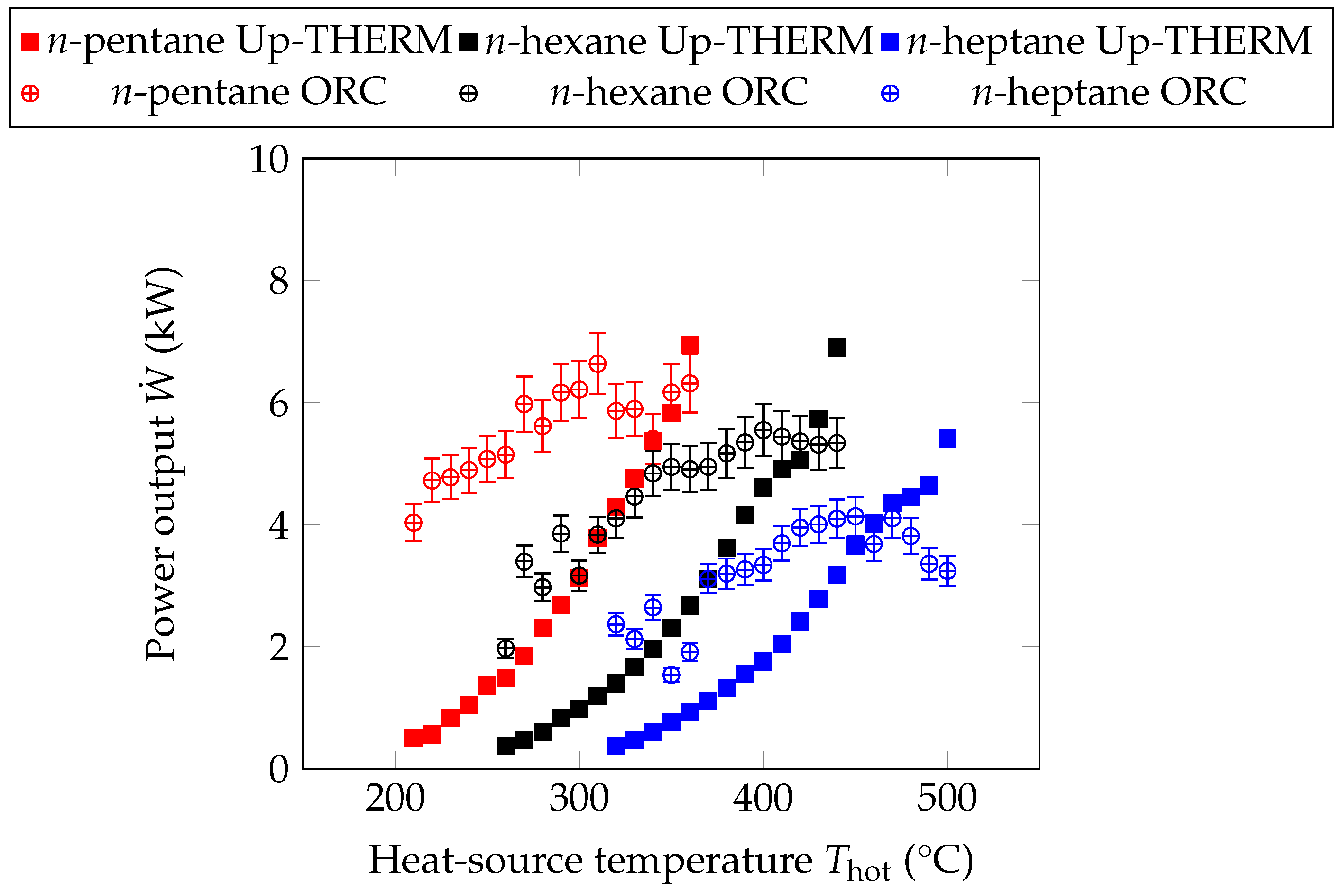
Figure 5 the power outputs of the Up-THERM heat converter and equivalent ORC engines for the three n-alkanes at different heat-source temperatures are shown. The marker of the ORC power output shows the cycle with an isentropic efficiency of the expander of 70%, while the error bars indicate the results for 65% and 75% isentropic efficiency, respectively. It can be seen that for low heat-source temperatures the power output of the ORC engine is generally higher than the power output of the Up-THERM heat converter. Furthermore, the power output generally increases with increasing heat-source temperature in both engines. In particular, for n-pentane the power output of the Up-THERM heat converter increases from 0.5 kW at 210 °C to 7.0 kW at 360 °C. For n-hexane the power output of the Up-THERM heat converter increases from 0.4 kW at 260 °C to 7.9 kW at 440 °C and for n-heptane from 0.4 kW at 320 °C to 5.4 kW at 500 °C.
In the same temperature ranges the net power output of the equivalent ORC engines rises from 4.0 kW (n-pentane), 2.0 kW (n-hexane) and 2.4 kW (n-heptane) to 6.6 kW (n-pentane), 5.6 kW (n-hexane) and 4.1 kW (n-heptane). Especially for n-hexane and n-heptane it can be observed that at increasing heat-source temperatures the difference in the power output of the two engines becomes less pronounced until, at the highest heat-source temperatures the Up-THERM heat converter surpasses the ORC engine in terms of power output. This is due to the heat input into both engines, which saturates at high heat-source temperatures for each working fluid. While for the Up-THERM heat converter the exergy input into the cycle, which is always increasing with increasing heat-source temperatures, is more relevant to create useful power, for the ORC engine the heat input is considered to create useful power. As the heat input saturates for high heat-source temperatures of each working fluid and the thermal efficiency is constant, the power output saturates as well.
For the Up-THERM heat converter the increasing power output is due to the increasing temperature difference between the heat source and heat sink and the increasing equilibrium pressure for increasing heat-source temperatures. A higher equilibrium pressure allows for higher amplitudes of pressure and volumetric displacement, which in turn leads to higher power outputs. Moreover, the heat input into the Up-THERM cycle increases with increasing heat-source temperature, due to the increasing temperature difference between heat source and working fluid and the increasing heat-transfer coefficient h. From Equation (2) it can be seen that h is dependent on the reduced pressure of the fluid. When the pressure increases, h increases and hence, the heat input into the Up-THERM cycle increases. As the heat input is equal for the same heat-source temperature and working fluid for the Up-THERM heat converter and the ORC engine, the heat input into the ORC engine also increases with increasing heat-source temperature. This leads to higher power outputs in the Up-THERM heat converter and the ORC engine.
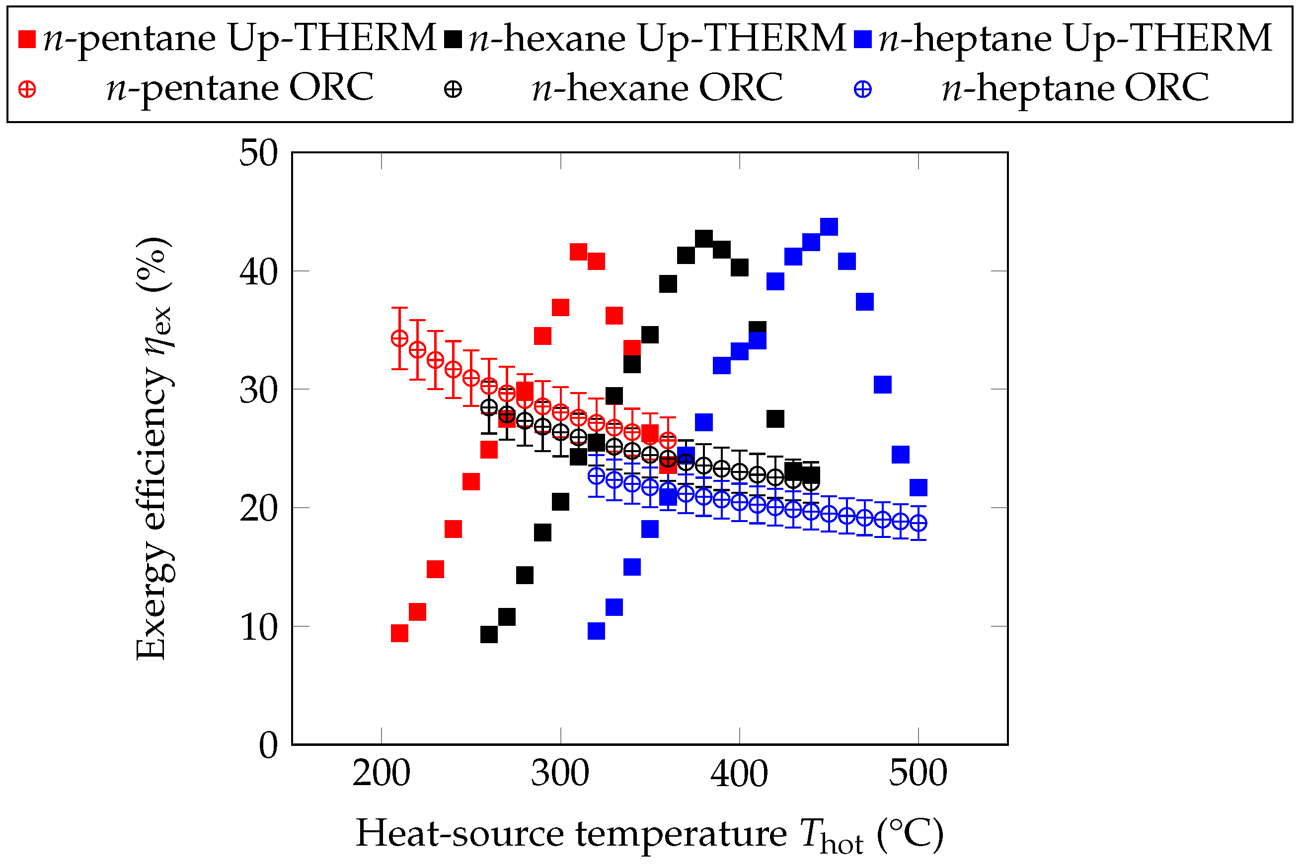
The exergy efficiencies of the Up-THERM heat converter and the ORC engine are shown in Figure 6 for the investigated n-alkanes and heat-source temperatures. As in Figure 5 for the ORC exergy efficiency the markers show results for 70% isentropic expander efficiency, while the error bars indicate the results for 65% and 75% respectively. The exergy efficiency of the ORC engine decreases from 34.3% at 210 °C to 25.7% at 360 °C for n-pentane, from 28.5% at 260 °C to 22.1% at 440 °C for n-hexane and from 22.7% at 320 °C to 18.7% at 500 °C for n-heptane. This is due to the constant thermal efficiency (14.2% for n-pentane, 13.3% for n-hexane and 11.9% for n-heptane) for the n-alkanes in the ORC engine, (Figure 7).
This constant thermal efficiency is a result of the sub-critical constraint on the ORC engines (i.e., evaporating the working fluid at sub-critical pressures) employed to maintain a phase-change similarity with the Up-THERM converter. Since the heat-source temperatures are higher than the critical temperatures of the working fluids, each working fluid is evaporated at the set sub-critical pressure limit (95% of the critical pressure), whereby the optimal cycles have similar profiles on a Ts or Ph diagram, and hence the resulting ORC engines have similar thermal efficiencies (Equation (23)). As the heat-source temperature increases, the Carnot (i.e., maximum possible) efficiency increases, leading to a decreasing exergy efficiency, which is consistent with its definition in Equation (23).
For the Up-THERM heat converter the exergy efficiencies of all three n-alkanes rise first with increasing heat-source temperature and, after having reached a maximum, decrease for further increasing heat-source temperatures. When the heat-source temperature increases, the heat input and exergy input into the cycle increase. However for temperatures above 310 °C (n-pentane), 400 °C (n-hexane) and 450 °C (n-heptane) the heat input saturates. This can be seen as the maximum heat input into the cycle for each working fluid. However, due to the increasing heat-source temperature, the exergy input into the cycle does not remain steady but increases further. This leads to a decreasing exergy efficiency. The maximum η ex for n-pentane is 41.6%, for n-hexane 42.7% and for n-heptane 43.7%. Thus, with increasing chain lengths of the n-alkanes, the maximum exergy efficiency increases. This is in contrast with the ORC engine, where with increasing chain length of the n-alkanes the maximum exergy efficiency decreases.
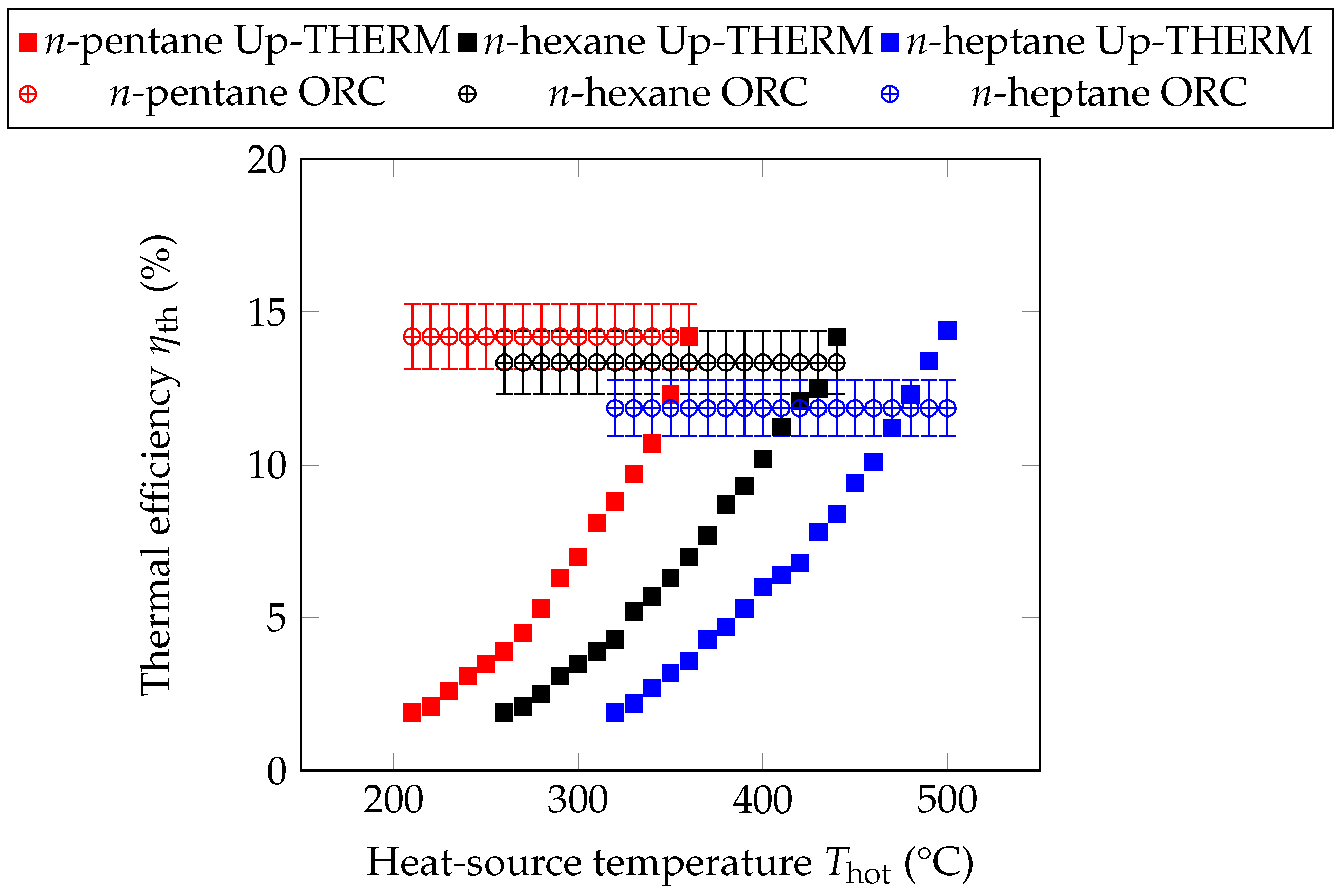
Next to the exergy efficiency the thermal efficiency is shown in Figure 7. The thermal efficiency of the Up-THERM engine increases for increasing heat-source temperatures. As the heat input and power output first increase with increasing heat-source temperatures, the thermal efficiency increases slowly. When the heat input saturates at the aforementioned temperatures, the increase of thermal efficiency becomes steeper. A higher heat-source temperature leads to higher equilibrium pressures and higher oscillation amplitudes of pressure and volumetric displacement. Thus, a higher pressure drop across the hydraulic motor can be observed, leading to higher power outputs. The power output is defined as W ˙ hm = R gen U hm U hm in Equation (13), with Δ P load = R gen U hm the pressure drop across the load. As the load resistance R load is determined empirically for maximum power output, its value grows for increasing heat-source temperatures.
The thermal efficiency of the ORC engine stays constant for every working fluid over the investigated temperature range as the working fluid is expanded from the saturated-vapour curve. For increasing chain-lengths of the n-alkanes, the thermal efficiency of the Up-THERM heat converter and the ORC engine decrease (at the same heat-source temperature). For the ORC engine this is due to the lower evaporation pressure, which is constant over the investigated temperature ranges for each respective working fluid. For the Up-THERM heat converter the equilibrium pressure decreases with increasing chain lengths of the n-alkanes, leading to a decreased power output (Figure 5) and decreasing thermal efficiency (Figure 7).
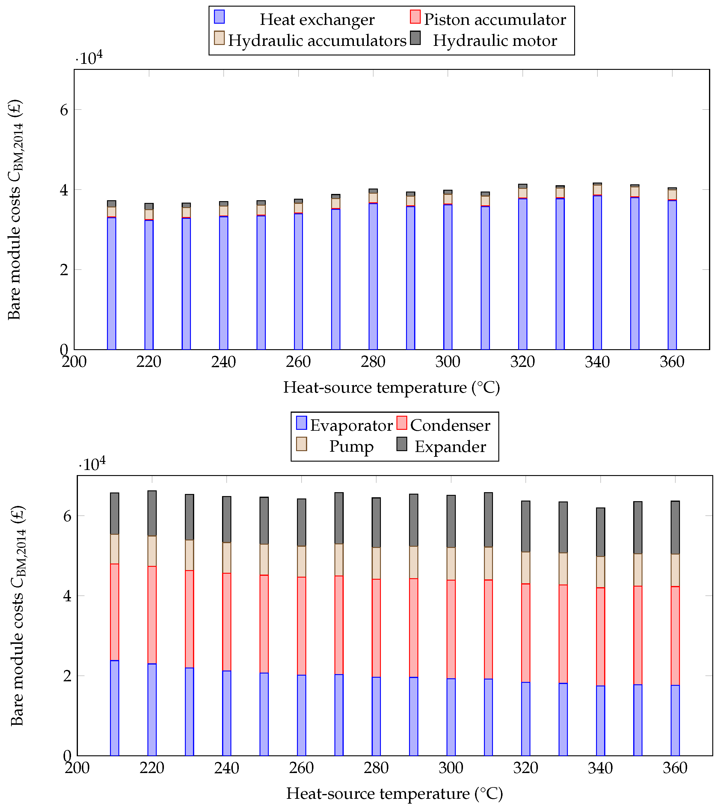
After having looked at the thermodynamic performance of the two engines, the economic performance is investigated in more detail. Therefore, in Figure 8, the bare module costs of the Up-THERM heat converter and the ORC engine for n-pentane at different heat-source temperatures are shown, which can be considered as capital costs of the two engines. The Up-THERM heat converter has lower capital costs than the ORC engine for all investigated heat-source temperatures. The biggest costs are associated with the heat exchangers in the Up-THERM heat converter and the ORC engine. In this paper it is implicit that the hot and cold heat-exchangers of the Up-THERM heat converter are the same size, as it is assumed that the equilibrium temperature lies half-way between the hot and cold heat-exchanger and thus, the length of both heat exchangers is identical. The piston accumulator and hydraulic motor have the smallest contribution to the capital costs of the Up-THERM heat converter, as these are commercially available off-the-shelf products. The hydraulic accumulators have slightly higher cost, due to the relatively high pressures they have to endure. The costs of the hydraulic motor decrease with increasing heat-source temperatures as the flow rate through it decreases, while the pressure drop across the hydraulic motor increases. Due to the decreasing flow rates smaller hydraulic motors can be utilized for higher temperatures.
The evaporator and condenser of the ORC engine contribute the most to its costs. The costs of the evaporator decrease for increasing heat-source temperatures, while the costs of the condenser stay almost constant over the investigated temperature range. As for higher heat-source temperatures the working fluid mass flow rate increases and hence more pump power is required, the pump costs increase for increasing heat source temperatures. Similarly, as the power output increases for increasing heat-source temperatures, the cost of the expander rises.
The simple design of the Up-THERM heat converter together with the utilization of commercially available products leads to the economic advantage over the ORC engine, which uses a pump and expander. Due to the increasing heat input into the cycle, which corresponds to increasing areas of the heat exchangers, and the dominating costs of the heat exchangers in the Up-THERM heat converter, the lowest capital costs are observed for low temperatures. The costs of the ORC heat exchangers are higher than the costs of the Up-THERM heat exchangers, as a larger area is required to evaporate/condense the working fluid.
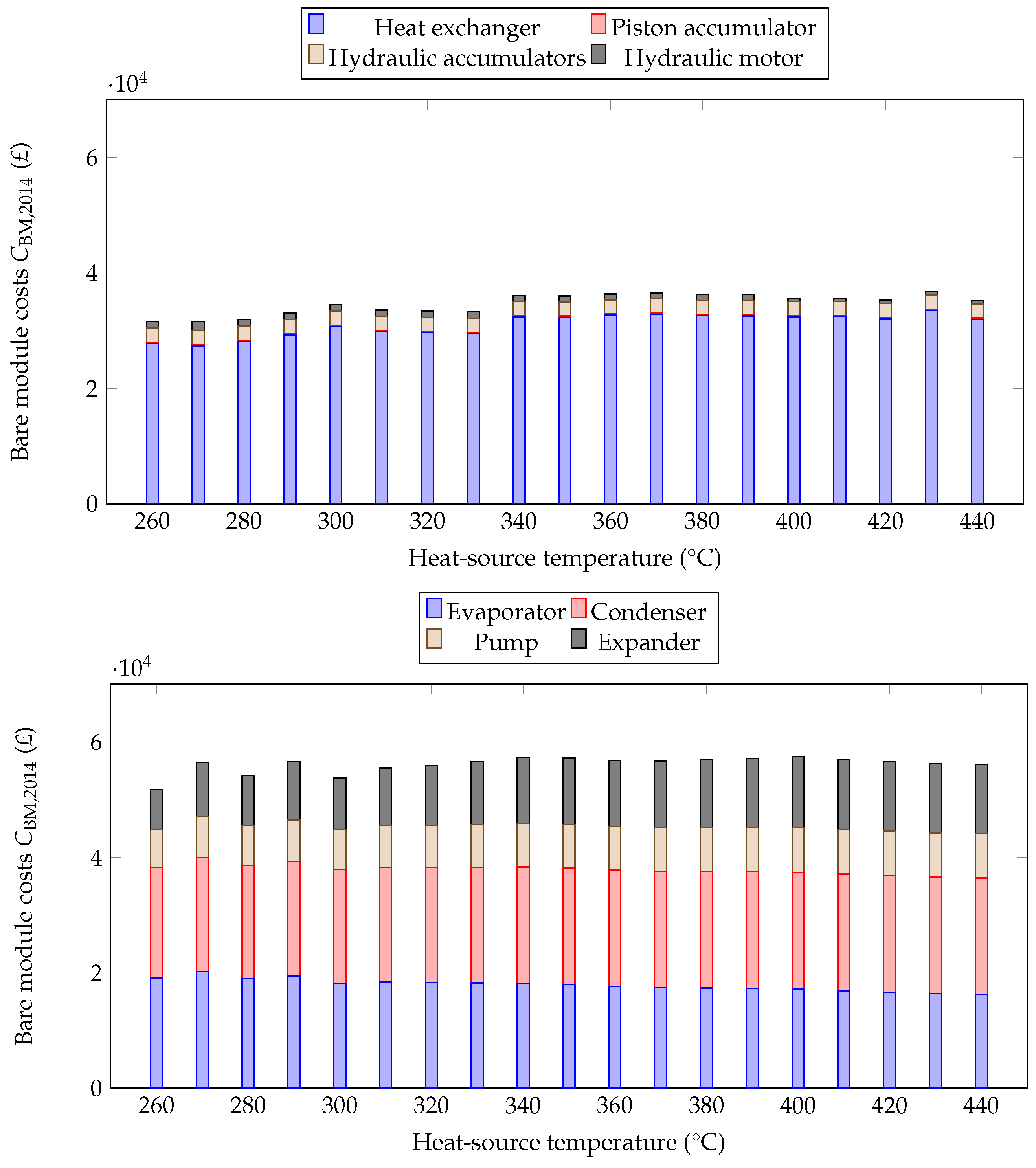
In Figure 9, the bare module costs of both engines are shown for n-hexane at heat-source temperatures between 260 °C and 440 °C. Similar to the previous figure for n-pentane the Up-THERM heat converter has lower capital costs than the ORC engine. In general the capital costs of the Up-THERM heat converter are about £6,000 lower for n-hexane than for n-pentane. This is due to the lower heat input into the cycle and consequently a smaller area of the heat exchangers, which leads to significantly lower overall costs, as the heat exchangers contribute the most to the Up-THERM costs. The costs of the ORC engine are approximately £10,000 lower for n-hexane than for n-pentane, due to smaller, and hence cheaper, heat exchangers.
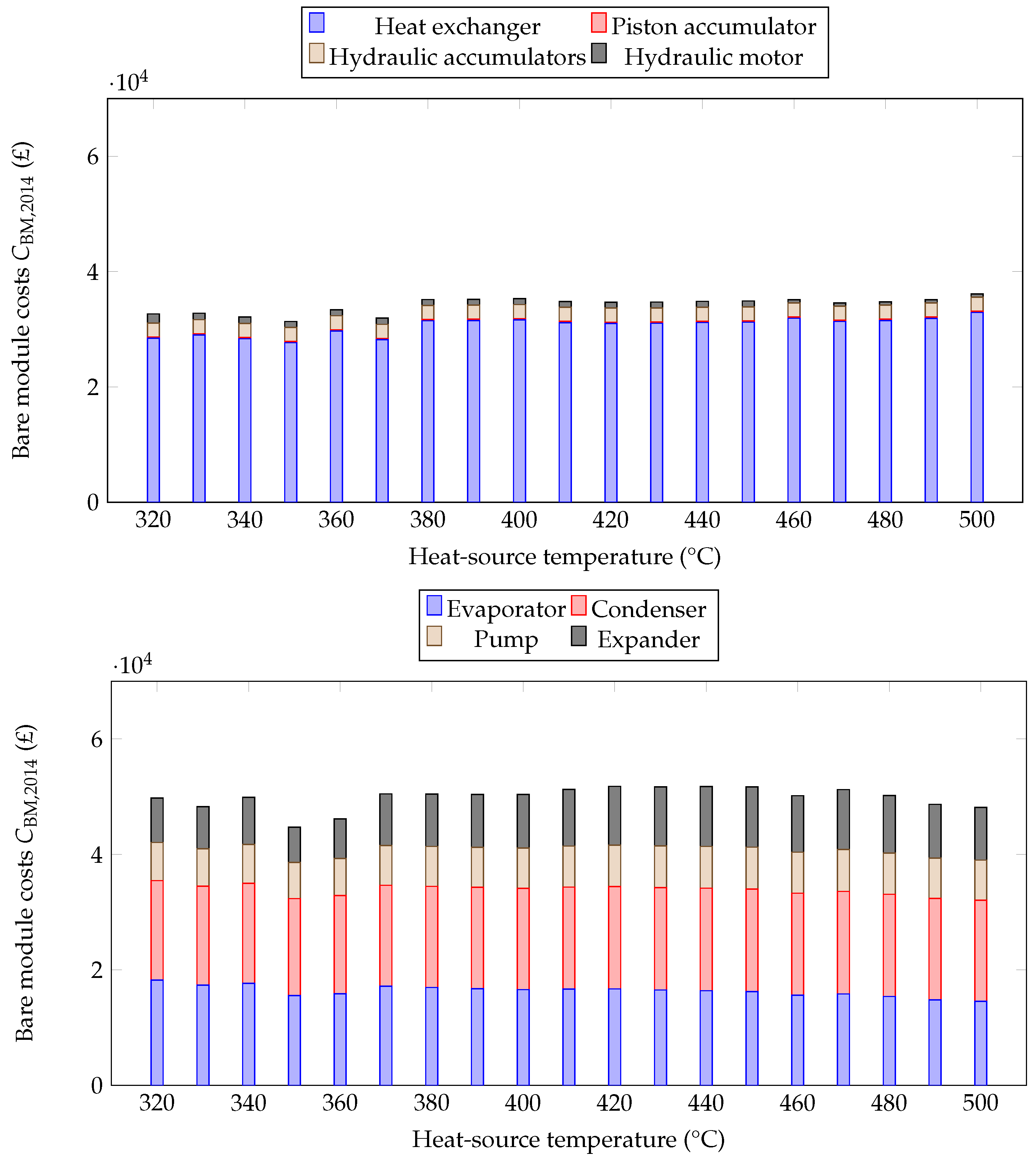
Finally, in Figure 10, the capital cots of the Up-THERM heat converter and the ORC engine for n-heptane are shown. The capital costs of both engines are approximately equal for n-heptane and n-hexane, due to similar-sized heat exchangers.
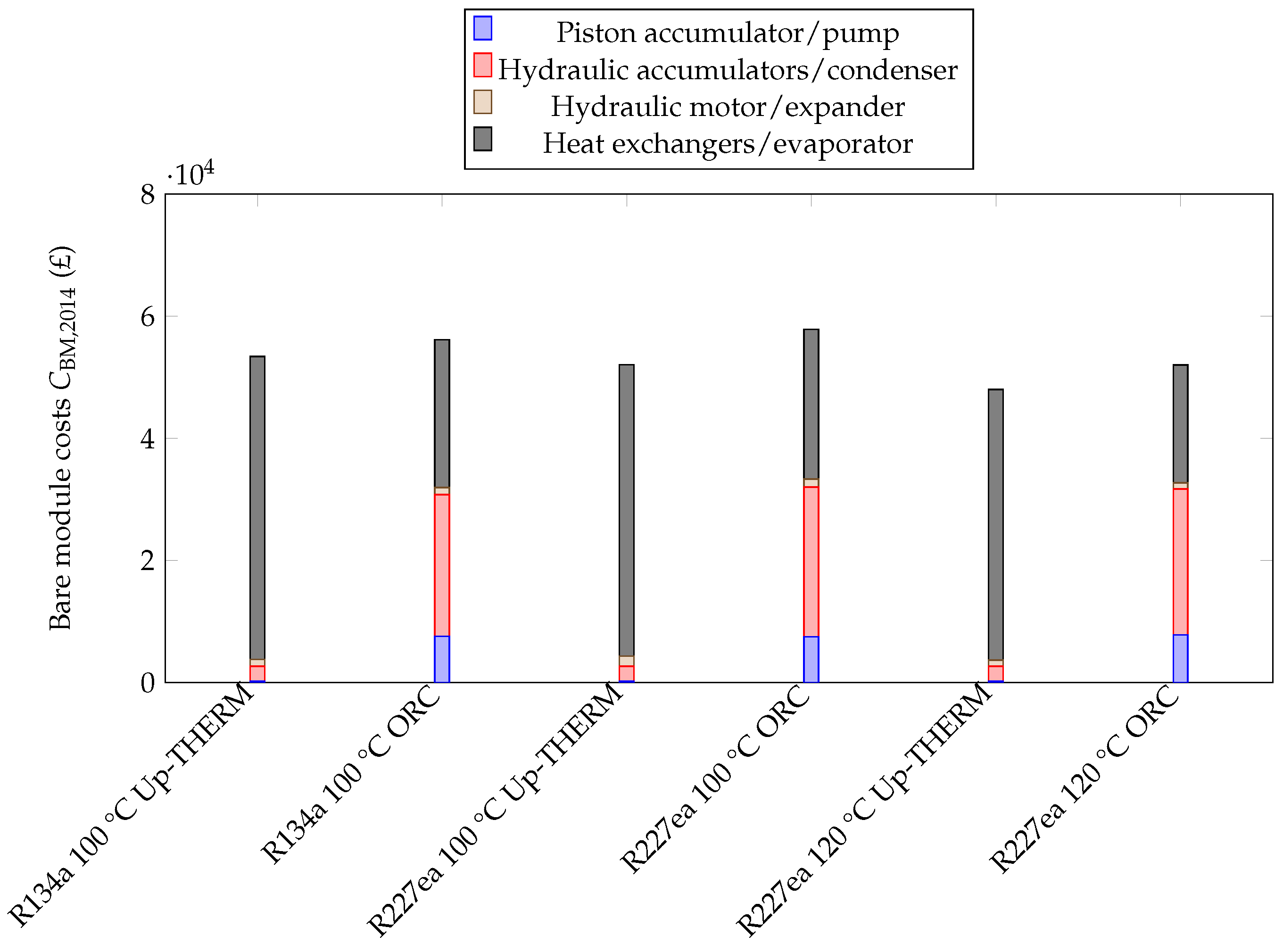
Next to applications in the aforementioned temperature range, a further thermo-economic comparison at temperatures of 100 °C and 120 °C is performed. For these temperatures the two refrigerants R134a and R227ea are considered as working fluids. The bare module costs for the Up-THERM heat converter and the ORC engine for R134a and R227ea are shown in Figure 11. It can be seen that the total costs of the Up-THERM heat converter are lower than the total costs of the ORC engine for each working fluid at the respective heat-source temperature. However, compared to n-pentane, n-hexane and n-heptane the capital costs are higher for those refrigerants in the investigated temperature range. This is mainly due to the larger area of the heat exchangers, which leads to higher bare module costs. In summary, it can be seen that the Up-THERM heat converter has lower up-front costs than the ORC engine for applications in all investigated temperature ranges.
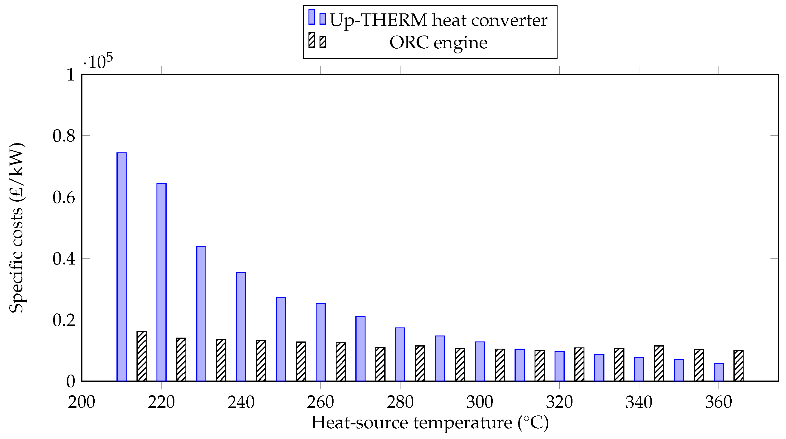
Next to the capital costs of the Up-THERM heat converter and ORC engine the specific capital costs are evaluated in this paper. The specific costs are expressed in £/kW and take the power output into account. At first, the specific costs of the Up-THERM heat converter and the ORC engine are compared for n-pentane as depicted in Figure 12. The specific capital costs decrease with increasing heat-source temperatures for both engines due to the rising power output and almost constant capital costs. At 210 °C the specific capital costs of the Up-THERM heat converter are about five times higher than those for the ORC engine. As the heat-source temperature increases the specific capital costs of the Up-THERM heat converter decrease more rapidly than those of the ORC engine (mainly due to the steeper increasing power output) so that at 310 °C the specific capital costs of the Up-THERM engine and the ORC engine are approximately equal. For heat-source temperatures above 310 °C the Up-THERM has lower specific costs, due to the further increasing power output of the Up-THERM heat converter, while the power output of the ORC engine remains steady.
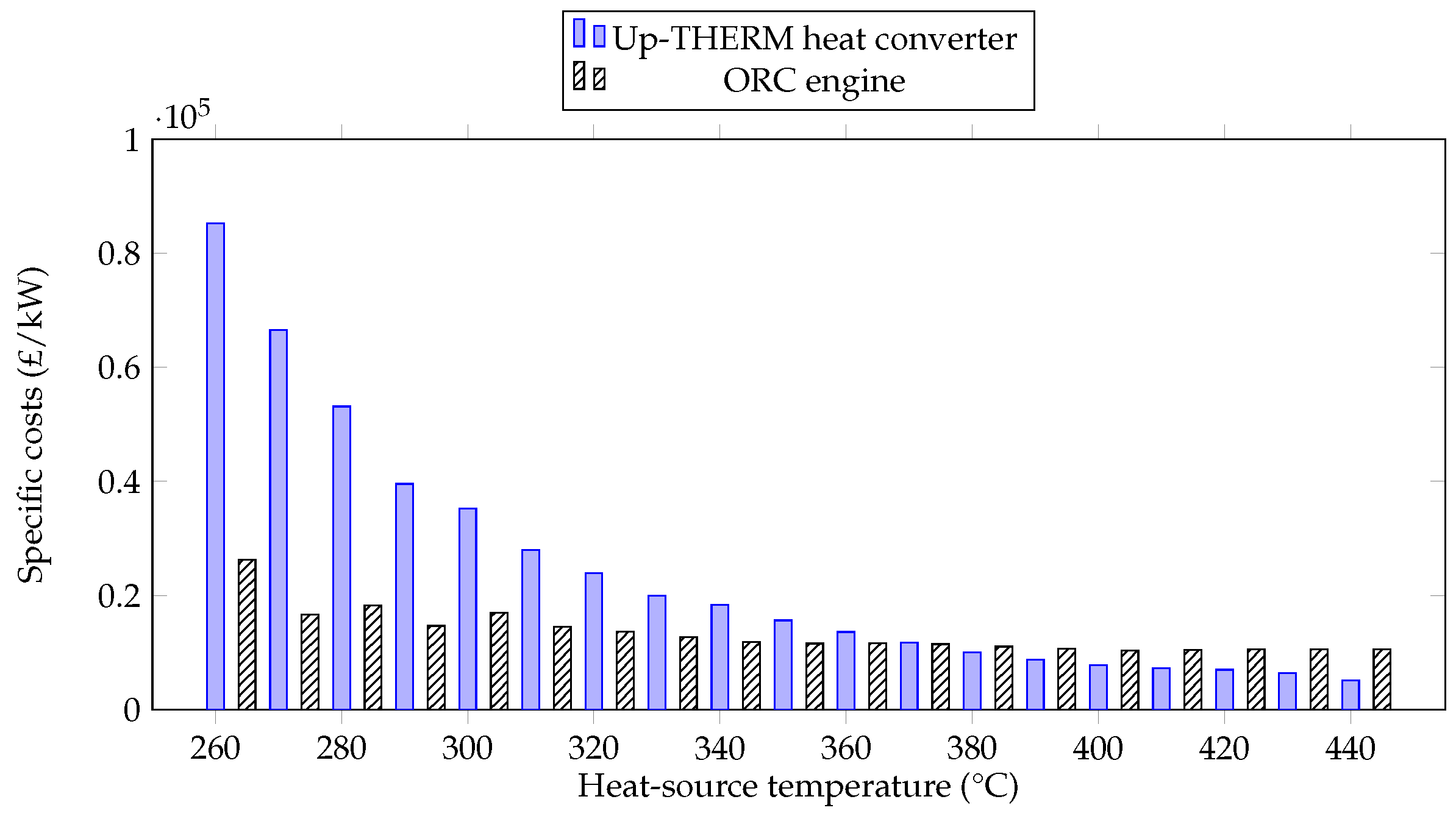
The specific capital costs for n-hexane are shown in Figure 13. For heat-source temperatures between 260 °C and 360 °C the Up-THERM heat converter has higher costs than the ORC engine. As the heat-source temperature increases the specific costs of both engines decrease. This is due to the increase in power output of both engines with increasing heat-source temperature, see also Figure 5. The capital costs of both engines remain fairly constant with increasing heat-source temperature, see Figure 9a,b. However, as the power output of the Up-THERM heat converter increases faster than the power output of the ORC engine, the specific costs of the Up-THERM heat converter decrease faster. In fact, at 370 °C heat-source temperature both engines have approximately the same specific costs and at 380 °C and above, the Up-THERM heat converter is approximately 1000 £/kW to 5000 £/kW cheaper than the ORC engine, which means that at 440 °C the specific costs of the Up-THERM heat converter are half of those of the ORC engine.
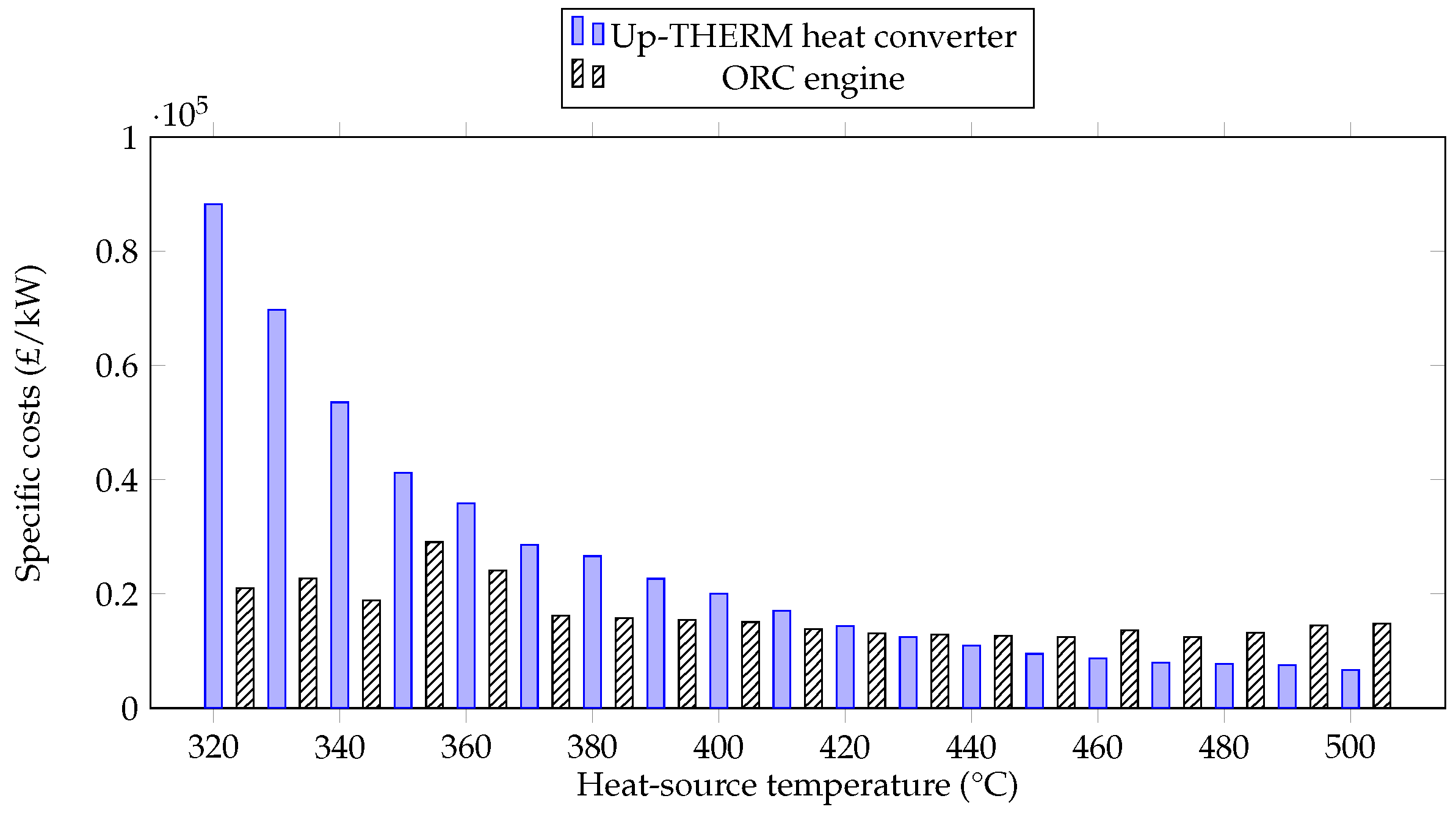
In Figure 14 the specific costs of the Up-THERM heat converter and the ORC engine are shown for n-heptane as the working fluid at different heat-source temperatures. Similarly to the cases for n-pentane and n-hexane, the specific costs for both engines decrease with increasing heat-source temperature due to the increasing power output and the constant capital costs. Also, the specific costs of the Up-THERM heat converter decrease faster than the specific costs of the ORC engine due to the steeper increase of the Up-THERM power output. For heat-source temperatures above 430 °C the ORC engine has higher specific costs than the Up-THERM heat converter.
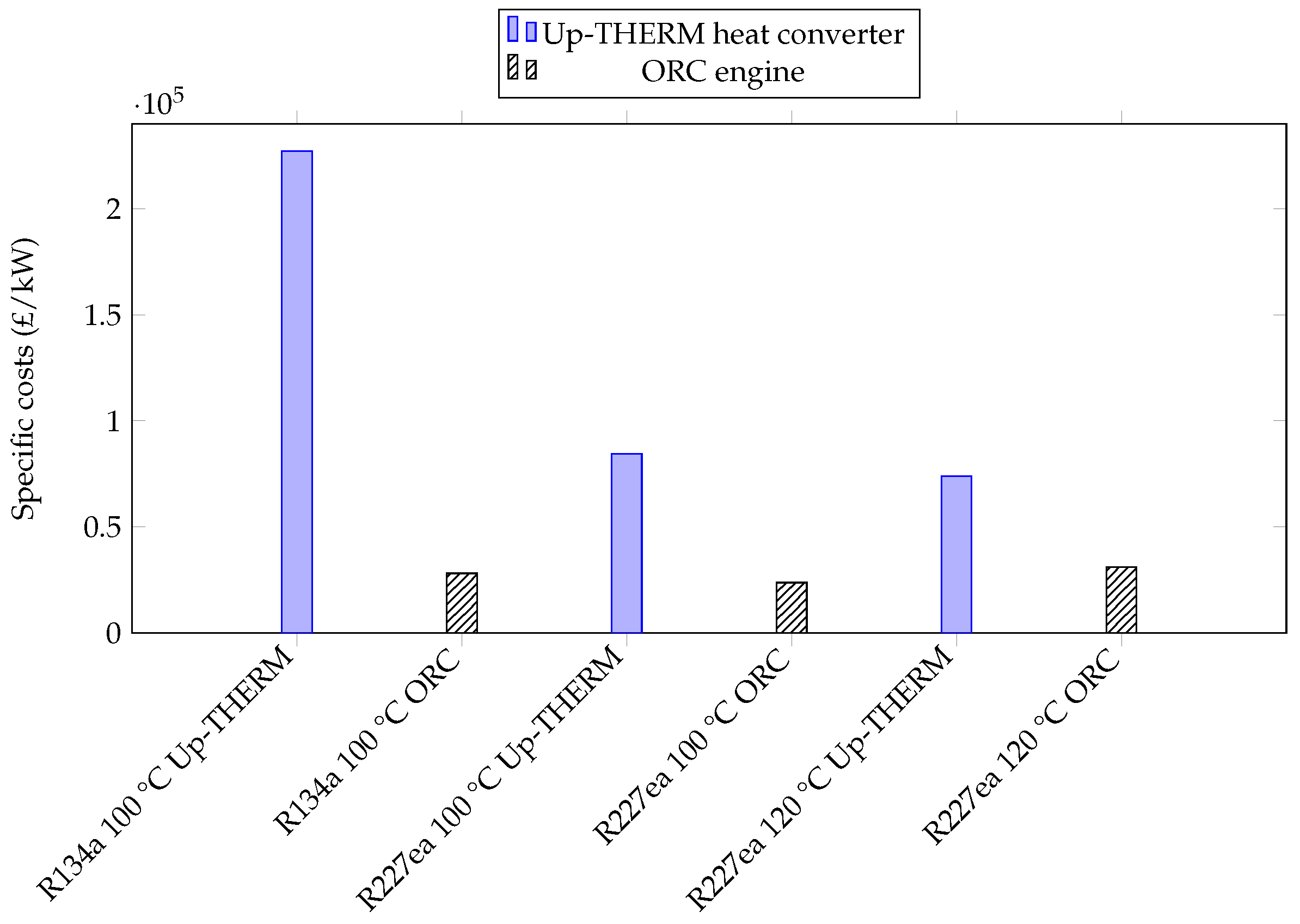
In Figure 15 we show the specific costs for the refrigerants R134a and R227ea for both the Up-THERM heat converter and the ORC engine. Although, the Up-THERM heat converter has lower capital costs for R134a than the ORC engine, the specific costs of the Up-THERM heat converter are much higher. In fact, the specific costs are the highest amongst all investigated fluids at all heat-source temperatures. These high specific costs are due to the low power output of the Up-THERM heat converter for R134a and R227ea, which range from 0.24 kW (R134a) to 0.65 kW (R227ea).
It should be noted that in this work only the capital costs of both engines are considered. The operating costs (such as maintenance) are not taken into account. Due to the simple design and lack of moving parts (e.g., no pump) it is expected that the Up-THERM heat converter has much lower operating expenses than the ORC engine. The maintenance interval of the Up-THERM heat converter is expected to be 50,000 h, which corresponds to over five years. For ORC engines the operating and maintenance costs can contribute to the total costs per operating hour almost as much as the investment costs [41].
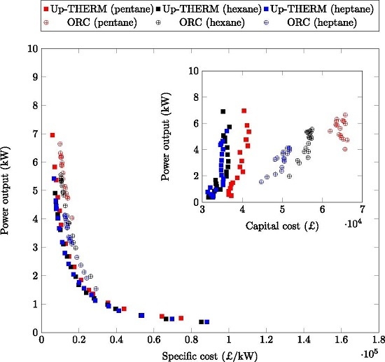
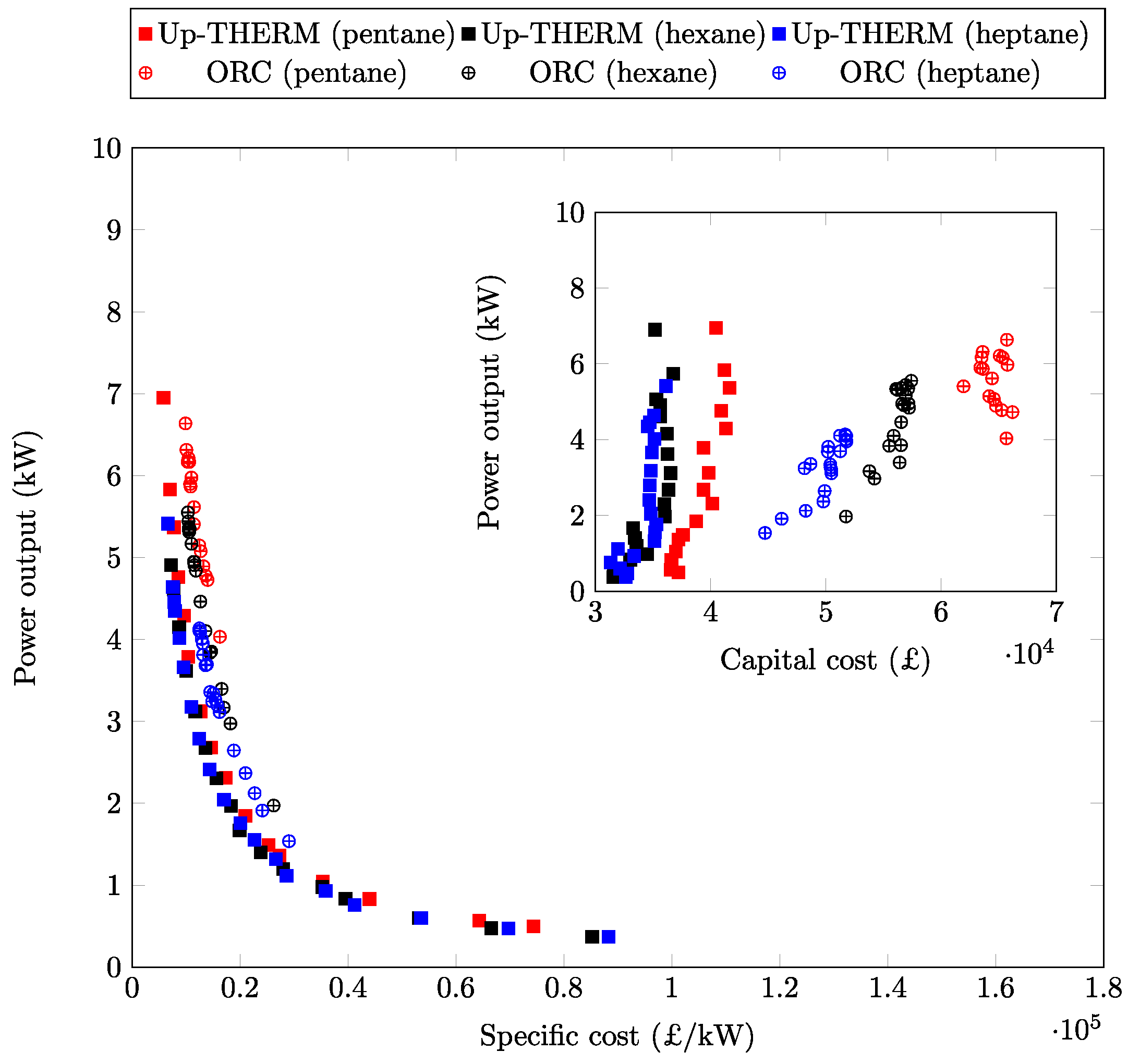
Lastly, we look at the capital and the specific costs of both engines using the three aforementioned n-alkanes as working fluids at different power outputs. In Figure 16 these costs are shown. For low heat source temperatures (e.g., n-pentane and n-heptane in the Up-THERM heat converter) the specific costs are high (over 80,000 £/kW). This is due to the low power output of the Up-THERM heat converter for low heat-source temperatures when using n-pentane or n-heptane as working fluids. With increasing heat source temperatures the specific costs first decrease rapidly, as the power output increases. However, for power outputs over 2 kW this decrease of the specific costs is less pronounced and appears to approach a lower limit. This indicates that there are minimum specific costs for both engine types that are approached for higher power outputs. As seen in Figure 8, Figure 9 and Figure 10 and the inset in Figure 16 the ORC capital costs are generally higher than the Up-THERM capital costs.

4. Conclusions

A pre-specified Up-THERM heat converter design in a selected prime-mover application has been compared thermodynamically and economically to an equivalent ORC heat engine when using five different working fluids over a range of heat-source temperatures between 210 °C and 500 °C. It is noted that ORC systems are a mature technology, with decades of development, operational and commercialization experience, whereas the Up-THERM is still in the early stages of development and needs to prove its commercial potential. It is also noted that the present effort only considers capital costs and does not account for operating/maintenance expenses which are expected to move the balance further in favor of the Up-THERM converter. This is expected, since the Up-THERM heat converter can be constructed from more simple components using low-cost manufacturing techniques and materials, and has fewer moving parts and dynamic seals, which allows longer maintenance cycles and lower operating costs than the ORC engine.
The power outputs of both engines increase at higher heat-source temperatures, while the capital costs do not change greatly with the heat-source temperature. Thus, the specific costs (in £/kW) of both systems decrease significantly at progressively higher temperatures, and this is especially true for the Up-THERM converter whose net power output also increases strongly at high temperatures.
Generally, for all the working fluids considered, the ORC engine outperforms its Up-THERM counterpart purely in terms of power output, exergy efficiency and thermal efficiency. However, the capital costs are always lower for the Up-THERM heat converter. For example, with n-pentane as the working fluid, the Up-THERM’s capital costs are only half those of the equivalent ORC engine. This leads to the possibility that at heat-source temperatures above 310 °C (for n-pentane), 380 °C (for n-hexane) and 430 °C (for n-heptane), the Up-THERM heat converter becomes the more affordable solution in terms of specific costs (relative to the equivalent ORC engine).
Thus, the Up-THERM heat converter can be regarded as an attractive alternative to the ORC engine at heat-source temperatures above 310 °C (n-pentane), above 380 °C (n-hexane) and above 430 °C (n-heptane), as the power output is comparable to or even higher than the power output of the equivalent ORC engine, while the specific costs are much lower. Since the capital costs of the Up-THERM converter are significantly lower than those of the ORC engine, the Up-THERM is an attractive solution over the entire investigated temperature range, for remote or off-grid power generation applications where low up-front costs are crucial.

Acknowledgments

This work was supported by the UK Engineering and Physical Sciences Research Council (EPSRC) [grant number EP/J006041/1]. The research leading to these results has also received funding from the European Community’s Seventh Framework Programme (FP7/2007–2013) under grant agreement number [605826]. Oyeniyi A. Oyewunmi gratefully acknowledges the funding awarded to him by the Nigerian government which allowed him to embark on this research. Data supporting this publication can be obtained on request from [email protected].

Author Contributions

This paper is part of the Ph.D. research of Christoph J.W. Kirmse and Oyeniyi A. Oyewunmi under the supervision of Andrew J. Haslam and Christos N. Markides.

Conflicts of Interest

The authors declare no conflict of interest. The founding sponsors had no role in the design of the study; in the collection, analyses, or interpretation of data; in the writing of the manuscript, and in the decision to publish the results.

Nomenclature

A ( m 2 ) Cross-sectional area
B i (-)Constants
C ( m 4 s 2 / kg ) Capacitance
C(£)Costs
c(-)Geometrical constant
c p ( J / kg K )Heat capacity at constant pressure
d ( m ) Diameter
F(-)Factor
f 0 (-)Friction factor
g ( m / s 2 ) Gravitational acceleration
h ( W / m 2 K ) Heat transfer coefficient
K i (-)Constants
k ( N/m ) Spring constant
L ( kg / m 4 ) Inductance
l ( m ) Length
m ( kg ) Mass
P ( Pa ) Pressure
Q ˙ ( W ) Heat flow-rate
R ( kg / m 4 s ) Resistance
S ˙ ( W / K ) Rate of entropy generation
s ( kJ / kg K ) Specific entropy
T(K)Temperature
t(s)Time
U ( m 3 / s ) Flow rate
V ( m 3 ) Volume
W ˙ (W)Power
y(-)Spatial coordinate
Greek letters
α (K)Temperature amplitude
β (1/m)Parameter that depends on the spatial gradient of the
heat exchanger wall temperature at equilibrium
γ (-)Heat capacity ratio
δ (m)Gap between piston and slide bearing
η (%)Efficiency
μ ( m 2 / s ) Dynamic (absolute) viscosity
ρ ( kg / m 3 ) Density
Subscripts
0 Equilibrium
1 ORC condenser outlet/pump inlet
2 ORC pump outlet/evaporator inlet
3 ORC evaporator outlet/expander inlet
4 ORC expander outlet/condenser inlet
a Hydraulic accumulator
b Slide bearing
BM Bare module
Ca Carnot
c Connection tube
cs Heat sink
cv Check valve
d Displacer cylinder
ex Exergy
exp Expander
fg Phase change
gen Power generating
hm Hydraulic motor
hot Hot heat exchanger
htf Heat transfer fluid
hx Heat exchanger
in Into the cycle
is Isentropic
LM Log mean
l Liquid volume
lub Lubricant
M Material
max Maximum
min Minimum
motor Motor
ms Mechanical spring
net Net power
nl Non-linear
out Out of the cycle
p Piston
p* Reduced pressure
pc Purchased costs of equipment
pump Pump
pv Piston valve
q Heat flux
ref Reference
sat Saturation
sh Shaft
ss Stainless steel
th Thermal domain
v Vapour volume
w Wall
wf Working fluid
wm Wall material
wr Wall surface roughness
Superscripts
0 Base condition

References

  1. Markides, C.N. The role of pumped and waste heat technologies in a high-efficiency sustainable energy future for the UK. Appl. Therm. Eng. 2013, 53, 197–209. [Google Scholar] [CrossRef]
  2. Markides, C.N. Low-concentration solar-power systems based on organic Rankine cycles for distributed-scale applications: Overview and further developments. Front. Energy Res. 2015, 3:47, 1–16. [Google Scholar] [CrossRef]
  3. Feldman, K.T.J. Review of the literature on Sondhauss thermoacoustic phenomena. J. Sound Vib. 1968, 7, 71–82. [Google Scholar] [CrossRef]
  4. Sondhauss, C. Über die Schallschwingungen der Luft in erhitzten Glasröhren und in gedeckten Pfeifen von ungleicher Weite. Ann. Phys. 1850, 155, 1–34. [Google Scholar] [CrossRef]
  5. Ceperley, P.H. A pistonless Stirling engine-The traveling wave heat engine. J. Acoust. Soc. Am. 1979, 66, 1508–1513. [Google Scholar] [CrossRef]
  6. Stammers, C.W. The operation of the Fluidyne heat engine at low differential temperatures. J. Sound Vib. 1979, 63, 507–516. [Google Scholar] [CrossRef]
  7. Smith, T.C.B. Thermally driven oscillations in dynamic applications. Ph.D. Thesis, University of Cambridge, Cambridge, UK, 2006. [Google Scholar]
  8. Smith, T.C.B. Asymmetric heat transfer in vapour cycle liquid-piston engines. In Proceedings of the 12th International Stirling Engine Conference and Technology Exhibition, Durham, UK, 7–9 September 2005; pp. 302–314.
  9. Smith, T.C.B. Power dense thermofluidic oscillators for high load applications. In Proceedings of the 2nd International Energy Conversion Engineering Conference, Providence, RI, USA, 16–19 August 2004; pp. 1–15.
  10. Markides, C.N.; Gupta, A. Experimental investigation of a thermally powered central heating circulator: Pumping characteristics. Appl. Energy 2013, 110, 132–146. [Google Scholar] [CrossRef]
  11. Markides, C.N.; Smith, T.C.B. A dynamic model for the efficiency optimization of an oscillatory low grade heat engine. Energy 2011, 36, 6967–6980. [Google Scholar] [CrossRef]
  12. Encontech B.V. Available online: http://www.encontech.nl (accessed on 10 March 2016).
  13. Glushenkov, M.; Sprenkeler, M.; Kronberg, A.; Kirillov, V. Single-piston alternative to Stirling engines. Appl. Energy 2012, 97, 743–748. [Google Scholar] [CrossRef]
  14. Up-THERM. Available online: http://labor1.wix.com/uptherm (accessed on 10 March 2016).
  15. Kirmse, C.J.W.; Taleb, A.I.; Oyewunmi, O.A.; Haslam, A.J.; Markides, C.N. A two-phase single-reciprocating-piston heat conversion engine. In Proceedings of the 11th International Conference on Heat Transfer, Fluid Mechanics and Thermodynamics, Kruger National Park, South Africa, 20–23 July 2015.
  16. Kirmse, C.J.W.; Taleb, A.I.; Oyewunmi, O.A.; Haslam, A.J.; Markides, C.N. Performance comparison of a novel thermofluidic organic-fluid heat converter and an organic Rankine cycle heat engine. In Proceedings of the 3rd International Seminar on ORC Power Systems, Brussels, Belgium, 12–14 October 2015.
  17. Kirmse, C.J.W.; Oyewunmi, O.A.; Taleb, A.I.; Haslam, A.J.; Markides, C.N. A two-phase single-reciprocating-piston heat conversion engine: Non-linear dynamic modelling. Appl. Energy 2016. [Google Scholar] [CrossRef]
  18. Oyewunmi, O.A.; Kirmse, C.J.W.; Müller, E.A.; Haslam, A.J.; Markides, C.N. Working-fluid selection for a two-phase single-reciprocating-piston heat-conversion engine. Appl. Energy 2016. [Google Scholar] [CrossRef]
  19. Taleb, A.I.; Timmer, M.A.G.; El-Shazly, M.Y.; Samoilov, A.; Kirillov, V.A.; Markides, C.N. A single-reciprocating-piston two-phase thermofluidic prime-mover. Energy 2016, 104, 250–265. [Google Scholar] [CrossRef]
  20. Lampe, M.; Kirmse, C.; Sauer, E.; Stavrou, M.; Gross, J.; Bardow, A. Computer-aided molecular design of ORC working fluids using PC-SAFT. Comput. Aided Chem. Eng. 2014, 34, 357–362. [Google Scholar]
  21. Oyewunmi, O.A.; Taleb, A.I.; Haslam, A.J.; Markides, C.N. On the use of SAFT-VR Mie for assessing large-glide fluorocarbon working-fluid mixtures in organic Rankine cycles. Appl. Energy 2016, 163, 263–282. [Google Scholar] [CrossRef]
  22. Oyewunmi, O.A.; Markides, C.N. Effect of working-fluid mixtures on organic Rankine cycle systems: Heat transfer and cost analysis. In Proceedings of the 3rd International Seminar on ORC Power Systems, Brussels, Belgium, 12–14 October 2015.
  23. Oyewunmi, O.A.; Taleb, A.I.; Haslam, A.J.; Markides, C.N. An assessment of working-fluid mixtures using SAFT-VR Mie for use in organic Rankine cycle systems for waste-heat recovery. Comput. Therm. Sci. Int. J. 2014, 6, 301–316. [Google Scholar] [CrossRef]
  24. Sartor, K.; Quoilin, S.; Dewallef, P. Simulation and optimization of a CHP biomass plant and district heating network. Appl. Energy 2014, 130, 474–483. [Google Scholar] [CrossRef]
  25. Desideri, A.; Gusev, S.; van den Broek, M.; Lemort, V.; Quoilin, S. Experimental comparison of organic fluids for low temperature ORC (organic Rankine cycle) systems for waste heat recovery applications. Energy 2016, 97, 460–469. [Google Scholar] [CrossRef]
  26. Lecompte, S.; Huisseune, H.; van den Broek, M.; Vanslambrouck, B.; Paepe, M.D. Review of organic Rankine cycle (ORC) architectures for waste heat recovery. Renew. Sustain. Energy Rev. 2015, 47, 448–461. [Google Scholar] [CrossRef]
  27. Lang, W.; Colonna, P.; Almbauer, R. Assessment of waste heat recovery from a heavy-duty truck engine by means of an ORC turbogenerator. J. Eng. Gas Turbines Power 2013, 135, 042313. [Google Scholar] [CrossRef]
  28. Huang, B.J.; Chuang, M.D. System design of orifice pulse-tube refrigerator using linear flow network analysis. Cryogenics 1996, 36, 889–902. [Google Scholar] [CrossRef]
  29. Backhaus, S.; Swift, G.W. A thermoacoustic-Stirling heat engine: Detailed study. J. Acoust. Soc. Am. 2000, 107, 3148–3166. [Google Scholar] [CrossRef] [PubMed]
  30. Backhaus, S.; Swift, G.W. A thermoacoustic Stirling heat engine. Nature 1999, 399, 335–338. [Google Scholar] [CrossRef]
  31. Solanki, R.; Galindo, A.; Markides, C.N. Dynamic modelling of a two-phase thermofluidic oscillator for efficient low grade heat utilization: Effect of fluid inertia. Appl. Energy 2012, 89, 156–163. [Google Scholar] [CrossRef]
  32. Solanki, R.; Mathie, R.; Galindo, A.; Markides, C.N. Modelling of a two-phase thermofluidic oscillator for low-grade heat utilisation: Accounting for irreversible thermal losses. Appl. Energy 2013, 106, 337–354. [Google Scholar] [CrossRef]
  33. Solanki, R.; Galindo, A.; Markides, C.N. The role of heat exchange on the behaviour of an oscillatory two-phase low-grade heat engine. Appl. Therm. Eng. 2013, 53, 177–187. [Google Scholar] [CrossRef]
  34. Markides, C.N.; Osuolale, A.; Solanki, R.; Stan, G.B.V. Nonlinear heat transfer processes in a two-phase thermofluidic oscillator. Appl. Energy 2013, 104, 958–977. [Google Scholar] [CrossRef]
  35. Gesellschaft, V. VDI Heat Atlas; Springer: Berlin/Heidelberg, Germany, 2010. [Google Scholar]
  36. Chen, H.; Goswami, D.Y.; Stefanakos, E.K. A review of thermodynamic cycles and working fluids for the conversion of low-grade heat. Renew. Sustain. Energy Rev. 2010, 14, 3059–3067. [Google Scholar] [CrossRef]
  37. Turton, R.; Bailie, R.C.; Whiting, W.B.; Shaeiwitz, J.A.; Bhattacharyya, D. Analysis, Synthesis, and Design of Chemical Processes; Pearson: Boston, MA, USA, 2012. [Google Scholar]
  38. Hewitt, G.F.; Shires, G.L.; Bott, T.R. Process Heat Transfer; CRC Press: Boca Raton, FL, USA, 1994. [Google Scholar]
  39. Seider, W.D.; Seader, J.D.; Lewin, D.R.; Widagdo, S. Product and Process Design Principles: Synthesis, Analysis, and Evaluation; Wiley: New York, NY, USA, 2010. [Google Scholar]
  40. CEPCI. Available online: http://www.chemengonline.com/pci (accessed on 10 March 2016).
  41. Ozdil, N.F.T.; Segmen, M.R. Investigation of the effect of the water phase in the evaporator inlet on economic performance for an organic Rankine cycle (ORC) based on industrial data. Appl. Therm. Eng. 2016, 100, 1042–1051. [Google Scholar] [CrossRef]
Figure 1. Schematic of the Up-THERM heat engine with hot heat-exchanger (HHX) and cold heat-exchanger (CHX), piston, piston valve, mechanical spring and hydraulic motor with piston at top dead centre (TDC) and bottom dead centre (BDC, inset).
Energies 09 00479 g001
Figure 2. Non-linear temperature profile along the inner surfaces of the heat-exchanger walls, showing a temperature saturation at long lengths from the origin (equilibrium position mid-way between the hot and cold heat exchangers).
Energies 09 00479 g002
Figure 3. Circuit diagram of the Up-THERM engine. The colors represent the same domains (thermal, fluid, and load) of the engine as shown in Figure 1.
Energies 09 00479 g003
Figure 4. Schematic of the sub-critical organic Rankine cycle (ORC) engine.
Energies 09 00479 g004
Figure 5. Power output from the Up-THERM heat converter and equivalent ORC engines for different working fluids at different heat-source temperatures. For the ORC engines, the circles indicate an expander isentropic efficiency of 0.70 and the error bars isentropic efficiencies of 0.65 and 0.75, respectively.
Energies 09 00479 g005
Figure 6. Exergy efficiency of the Up-THERM heat converter and equivalent ORC engines for different working fluids at different heat-source temperatures. For the ORC engines, the circles indicate an expander isentropic efficiency of 0.70 and the error bars isentropic efficiencies of 0.65 and 0.75, respectively.
Energies 09 00479 g006
Figure 7. Thermal efficiency of the Up-THERM heat converter and equivalent ORC engines for different working fluids at different heat-source temperatures. For the ORC engines, the circles indicate an expander isentropic efficiency of 0.70 and the error bars isentropic efficiencies of 0.65 and 0.75, respectively.
Energies 09 00479 g007
Figure 8. Bare module costs for n-pentane as the working fluid at different heat-source temperatures: (a) Up-THERM heat converter; and (b) equivalent ORC engines.
Energies 09 00479 g008
Figure 9. Bare module costs for n-hexane as the working fluid at different heat-source temperatures: (a) Up-THERM heat converter; and (b) equivalent ORC engines.
Energies 09 00479 g009
Figure 10. Bare module costs for n-heptane as the working fluid at different heat-source temperatures: (a) Up-THERM heat converter; and (b) equivalent ORC engines.
Energies 09 00479 g010
Figure 11. Bare module costs for the Up-THERM heat converter and equivalent ORC engines for the refrigerants R134a and R227ea as working fluids at different heat-source temperatures.
Energies 09 00479 g011
Figure 12. Specific costs for the Up-THERM heat converter and equivalent ORC engines for n-pentane as the working fluid at different heat-source temperatures.
Energies 09 00479 g012
Figure 13. Specific costs for the Up-THERM heat converter and equivalent ORC engines for n-hexane as the working fluid at different heat-source temperatures.
Energies 09 00479 g013
Figure 14. Specific costs for the Up-THERM heat converter and equivalent ORC engines for n-heptane as working fluid at different heat-source temperatures.
Energies 09 00479 g014
Figure 15. Specific costs for the Up-THERM heat converter and equivalent ORC engines for R134a and R227ea as working fluids at different heat-source temperatures.
Energies 09 00479 g015
Figure 16. Capital cost (inset) and specific cost of the Up-THERM heat converter and ORC engines plotted over the respective power output.
Energies 09 00479 g016
Table 1. Values for the linear electrical components shown in Figure 3.
Thermal-Fluid EffectComponentNominal ValuesUnit
Connection tube resistance R c 1 . 32 × 10 3 kg·m 4 ·s 1
Hydraulic motor resistance R hm 4 . 31 × 10 5 kg·m 4 ·s 1
Displacer cylinder resistance R d 3 . 21 × 10 3 kg·m 4 ·s 1
Leakage flow resistance 1 R l , 1 3 . 39 × 10 7 kg·m 4 ·s 1
Leakage flow resistance 2 R l , 2 6 . 45 × 10 5 kg·m 4 ·s 1
Fluid flow in load pipes R t , 1 / 2 2 . 09 × 10 4 kg·m 4 ·s 1
Piston resistance R p 4 . 29 × 10 4 kg·m 4 ·s 1
Fluid flow resistance in slide bearing R b , l 2 . 19 × 10 7 kg·m 4 ·s 1
Piston resistance in slide bearing R b , p 3 . 19 × 10 5 kg·m 4 ·s 1
Thermal resistance R th 2 . 41 × 10 7 kg·m 4 ·s 1
Connection tube inductance L c 3 . 12 × 10 5 kg·m 4
Hydraulic motor inductance L hm 3 . 09 × 10 5 kg·m 4
Displacer cylinder inductance L d 1 . 88 × 10 5 kg·m 4
Leakage flow inductance L l 6 . 45 × 10 7 kg·m 4
Fluid flow in load pipes L t , 1 / 2 1 . 42 × 10 6 kg·m 4
Piston inductance L p 5 . 96 × 10 6 kg·m 4
Fluid flow inductance in slide bearing L b , l 8 . 28 × 10 6 kg·m 4
Piston inductance in slide bearing L b , p 4 . 42 × 10 6 kg·m 4
Displacer cylinder capacitance C d 8 . 18 × 10 8 m 4 ·s 4 ·kg 1
Leakage flow capacitance C l 1 . 78 × 10 10 m 4 ·s 4 ·kg 1
Piston capacitance C p 6 . 02 × 10 10 m 4 ·s 4 ·kg 1
Hydraulic accumulator capacitance C a , 1 / 2 1 . 25 × 10 9 m 4 ·s 4 ·kg 1

