A Novel Full-Digital Protocol (SCAN-PLAN-MAKE-DONE®) for the Design and Fabrication of Implant-Supported Monolithic Translucent Zirconia Crowns Cemented on Customized Hybrid Abutments: A Retrospective Clinical Study on 25 Patients


Abstract
:1. Introduction
2. Methods
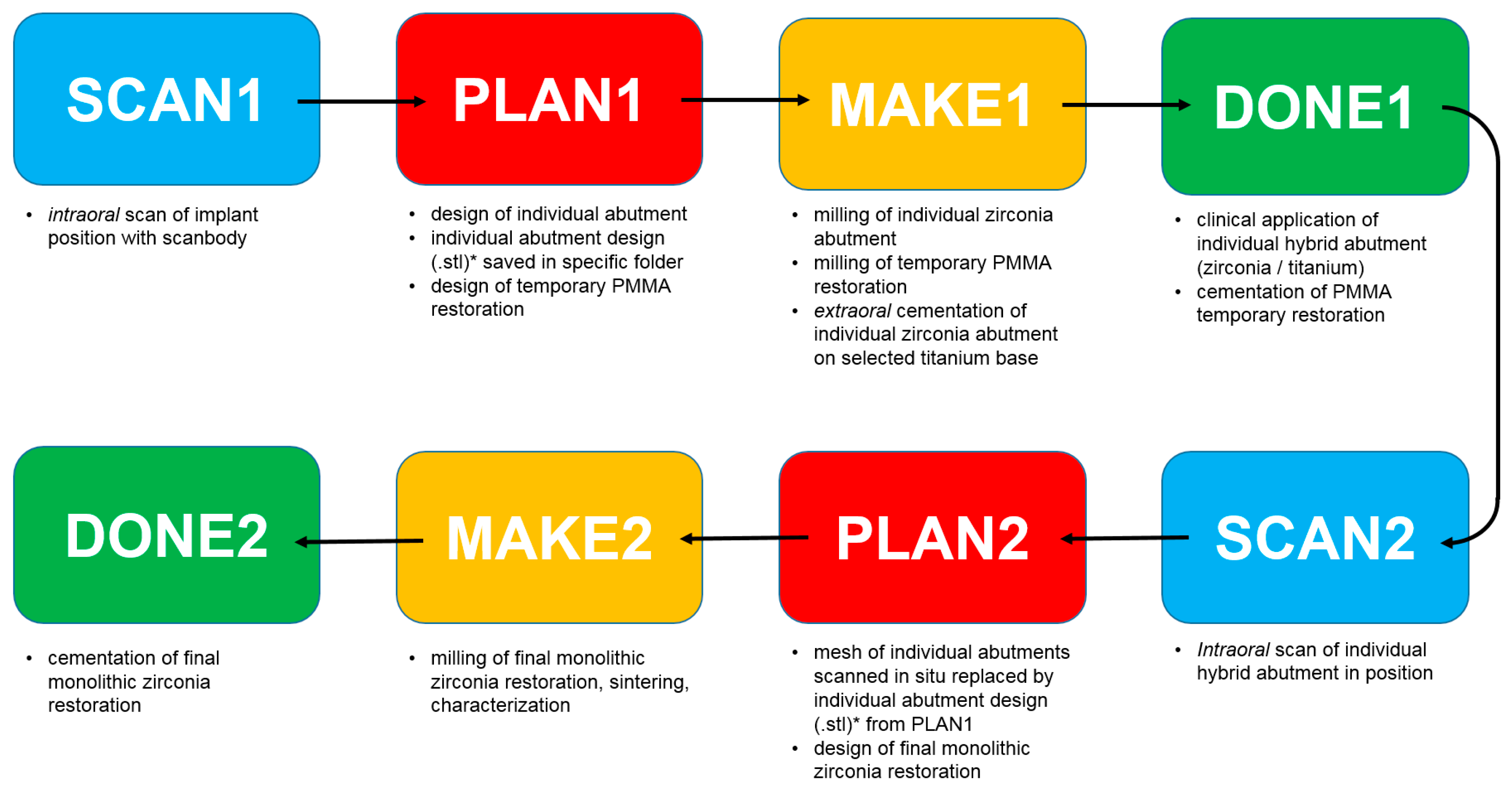
2.1. Study Design
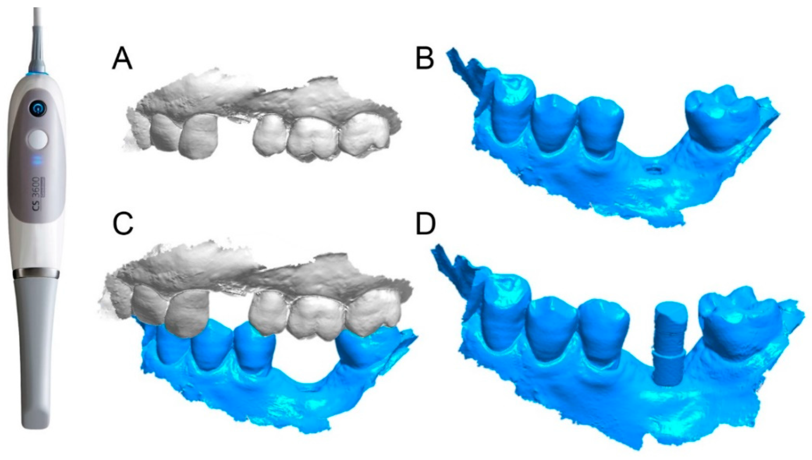
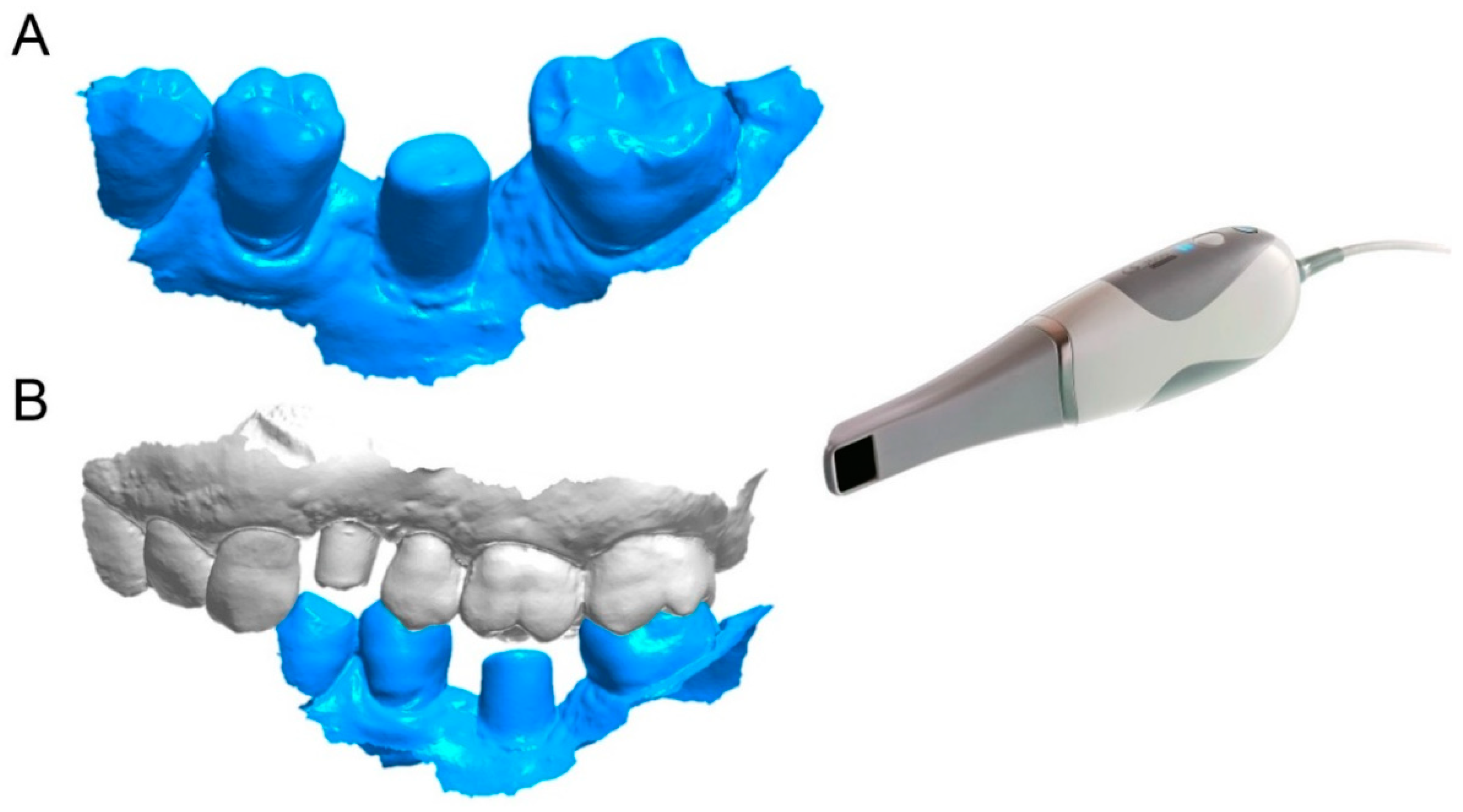
- SCAN1: intraoral scan of the implant position with scanbody;
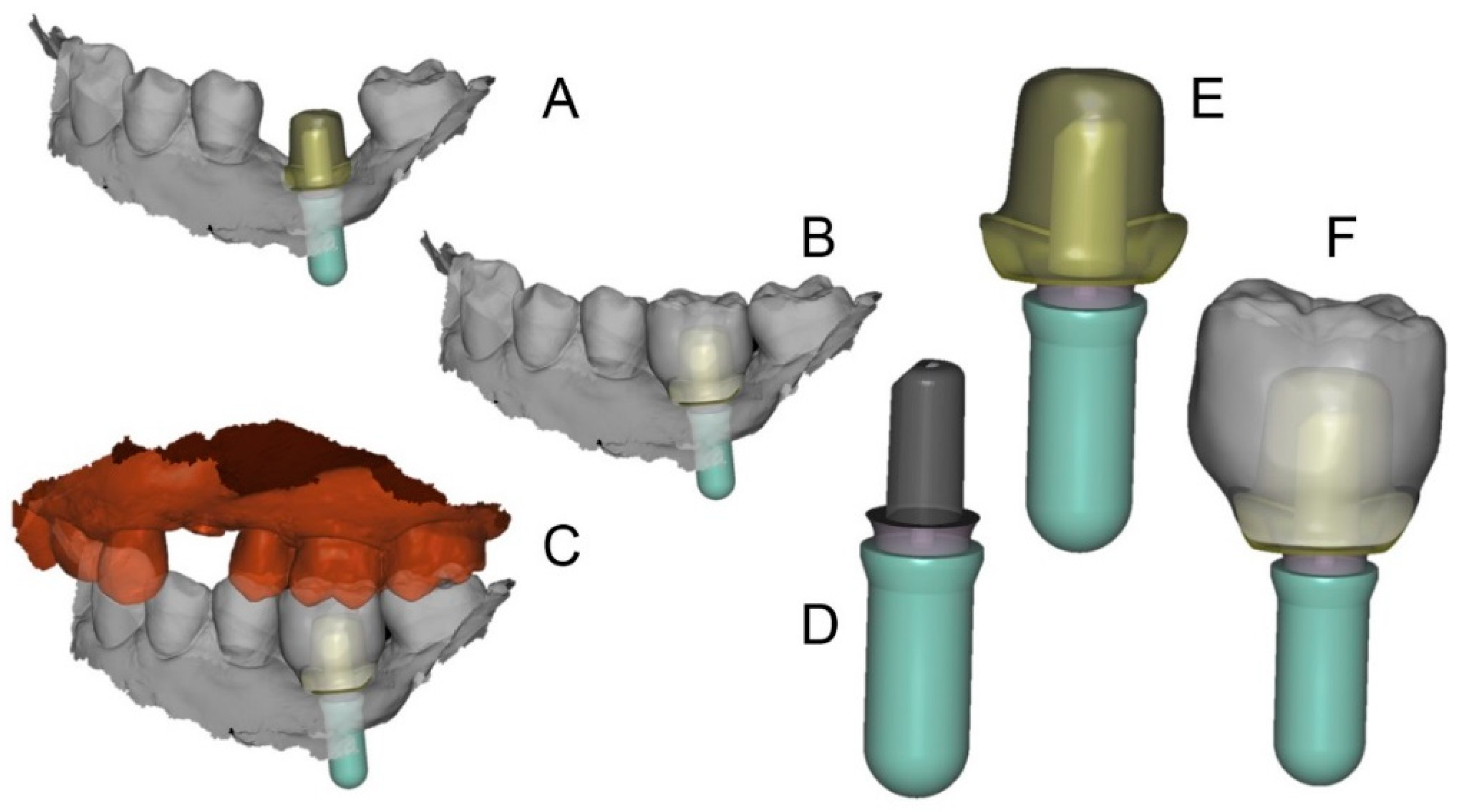
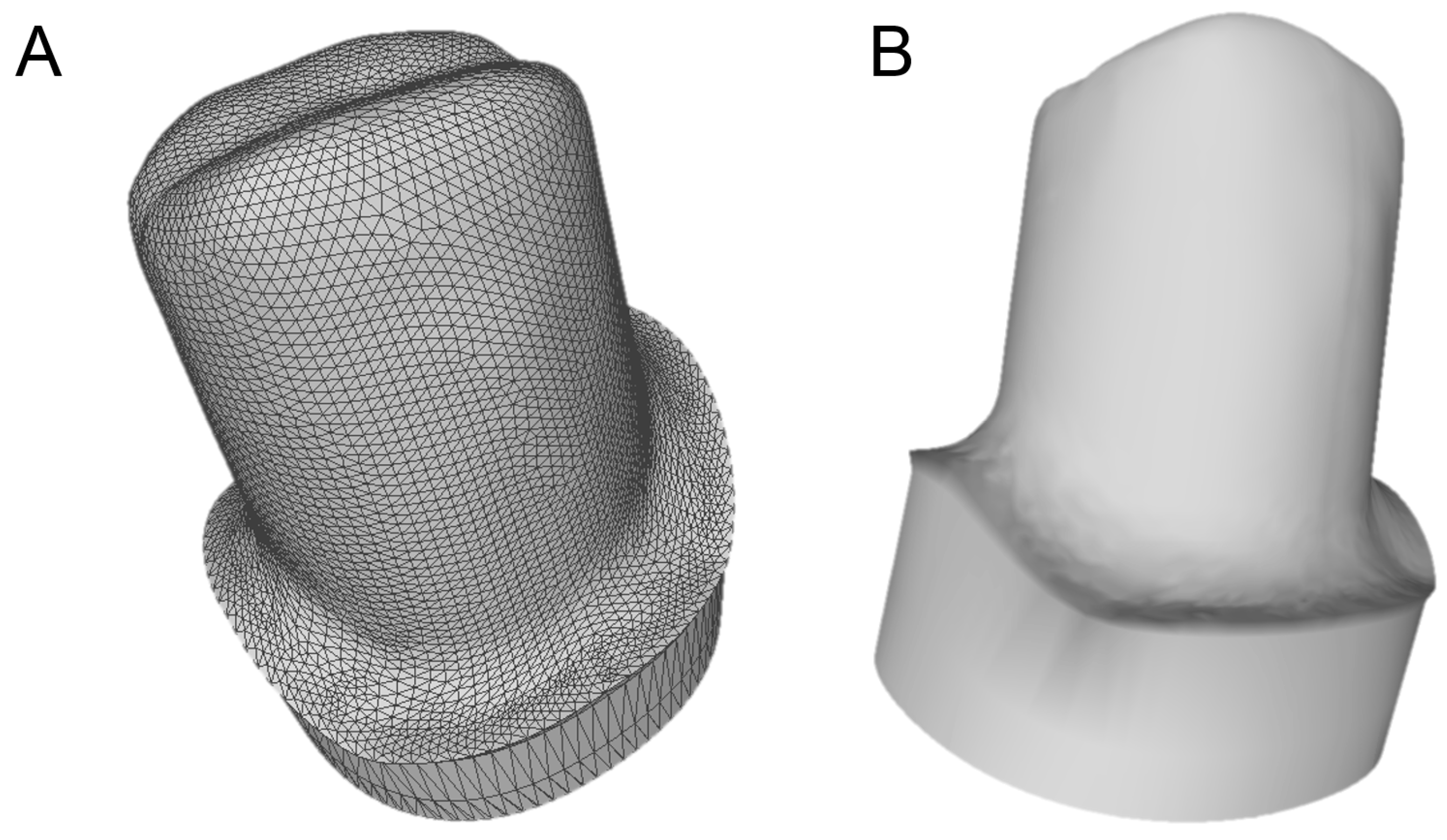
- PLAN 1: design of the individual abutment from library files (bonding bases) and design of the temporary PMMA restoration; the files of the individual abutment (original CAD drawing) thus modeled are saved (as .STL files) in a specific folder, labeled as “supplementary abutment design”, ready to be recalled in the following phases:
- MAKE1: milling of the individual zirconia abutment and of the temporary PMMA crown, and subsequent extraoral cementation of the individual zirconia abutment on the relative titanium bonding base, to generate an individual hybrid abutment;
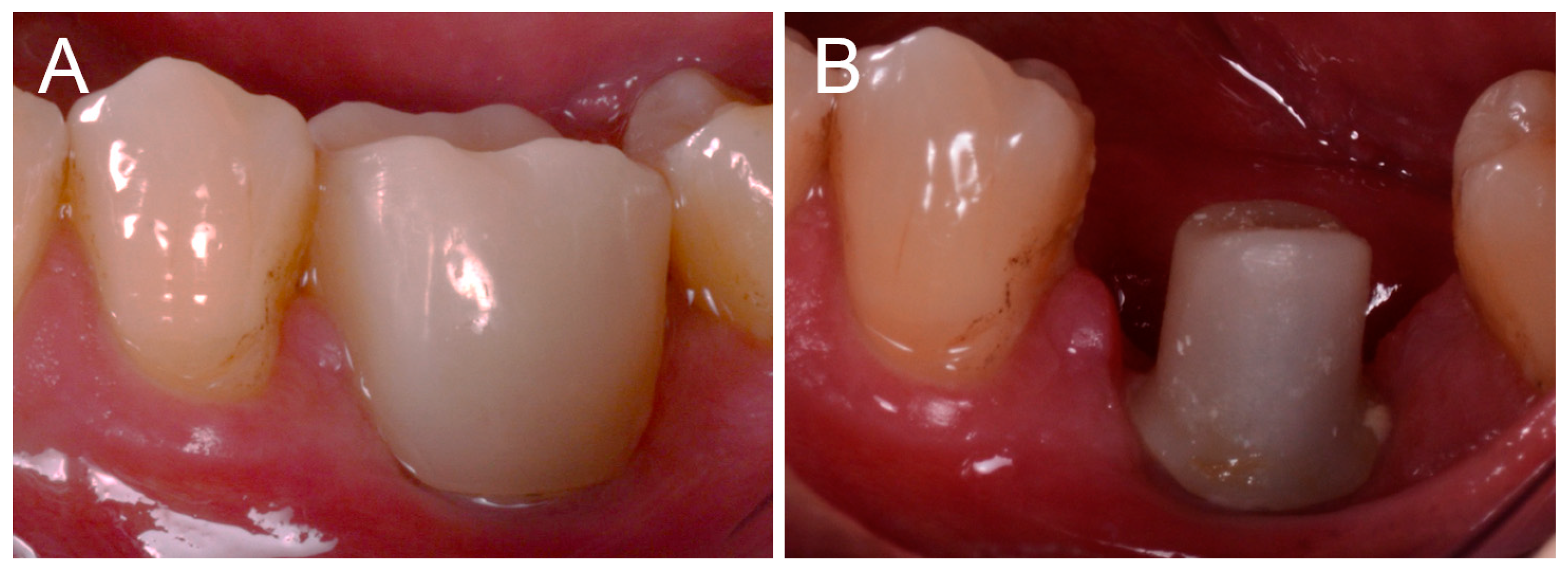
- DONE1: clinical application of the individual hybrid abutment and cementation of the PMMA temporary crown above it;
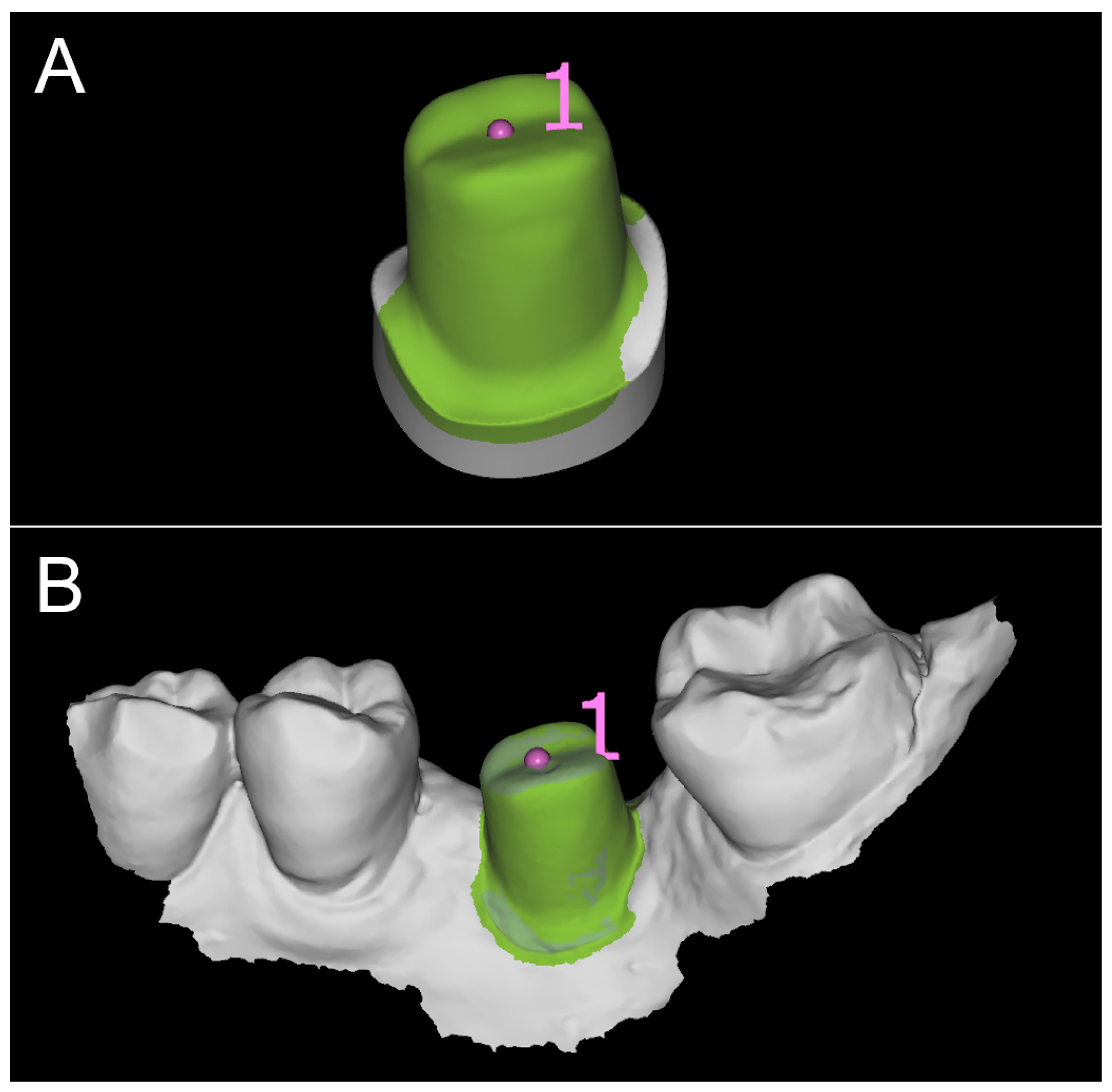
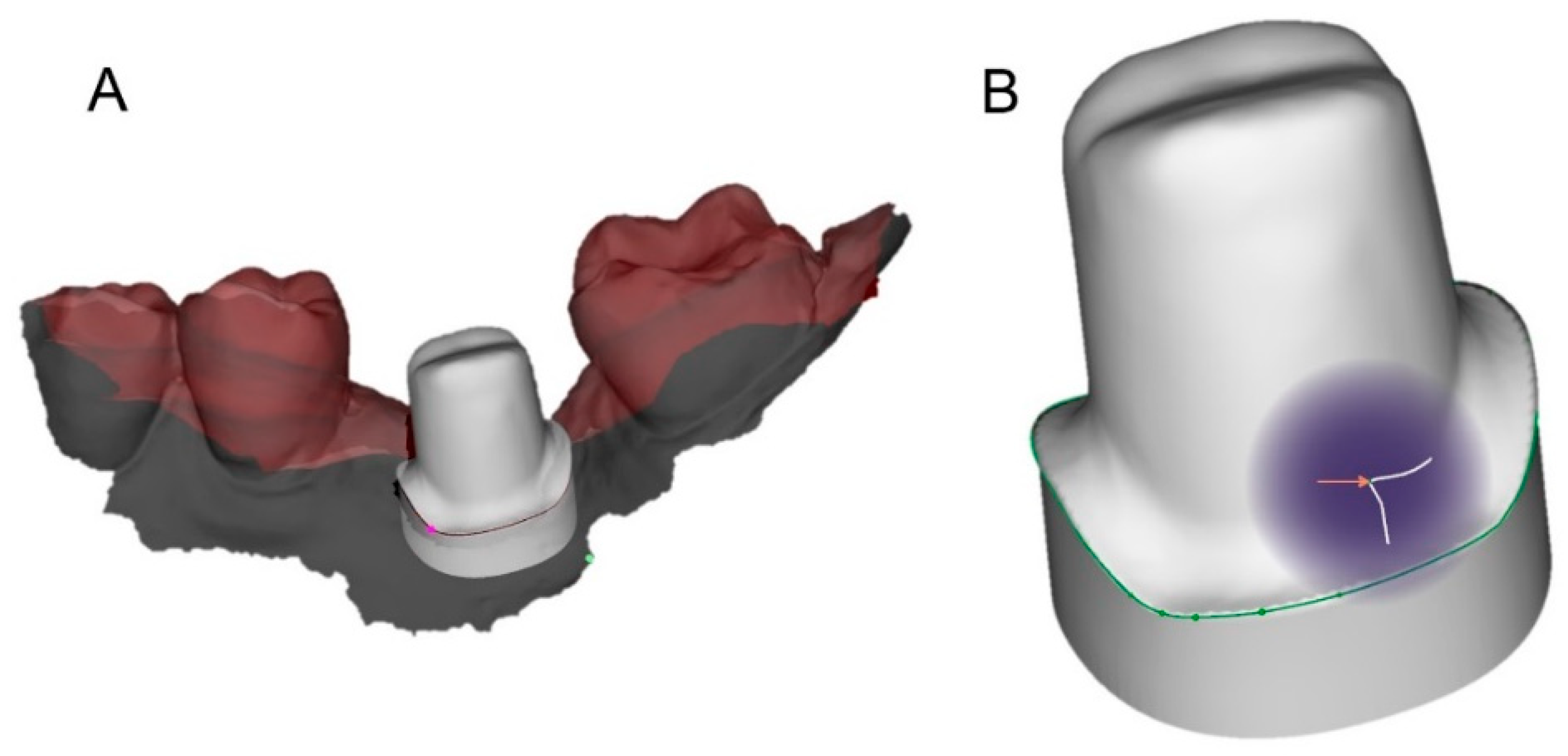
- SCAN2: intraoral scan of the individual hybrid abutment in the mouth, in position, after removing the temporary crown;
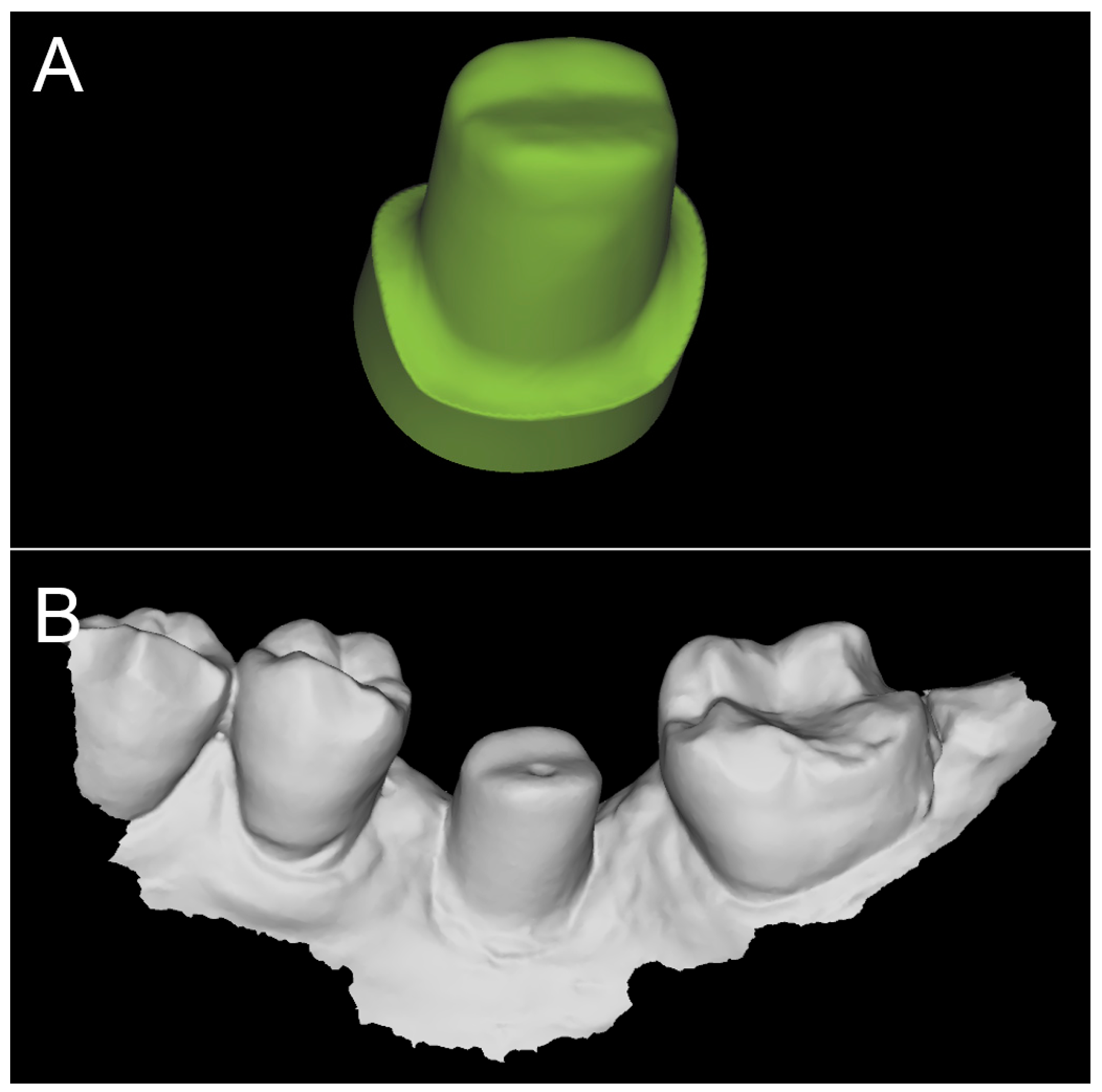
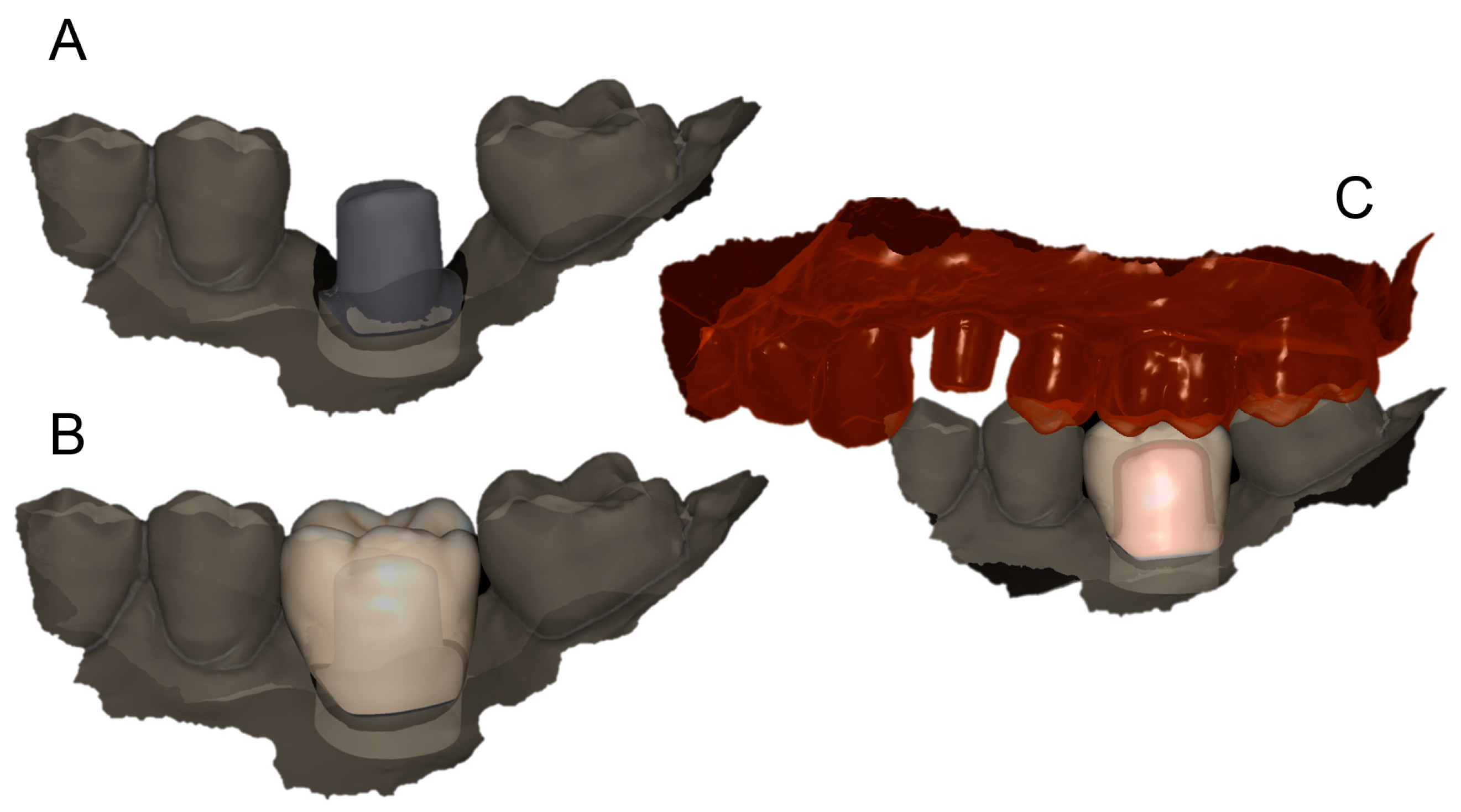
- PLAN2: in the definitive CAD scene, the mesh of the abutment in the correct position in the mouth is replaced by the .STL file of the individual abutment (“supplementary abutment design”, original CAD drawing) that was previously stored in a specific folder; the dental technician proceeds to model the final crown;
- MAKE2: milling of the final crown in monolithic translucent zirconia, sintering and characterization;
- DONE2: clinical application of the final crown in monolithic translucent zirconia.
2.2. Inclusion and Exclusion Criteria
2.3. Detail of Prosthetic Procedures
2.4. Outcome Variables
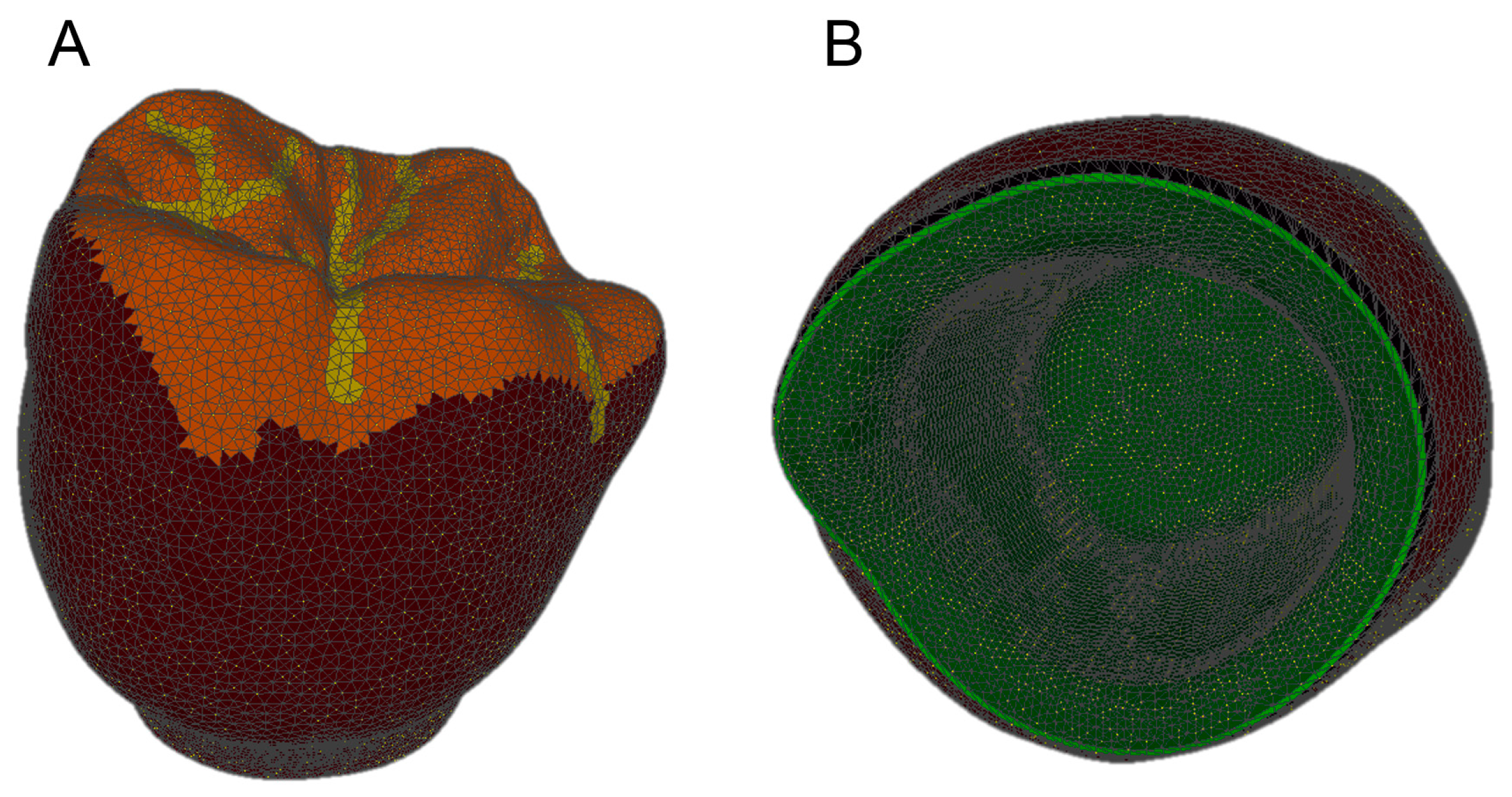
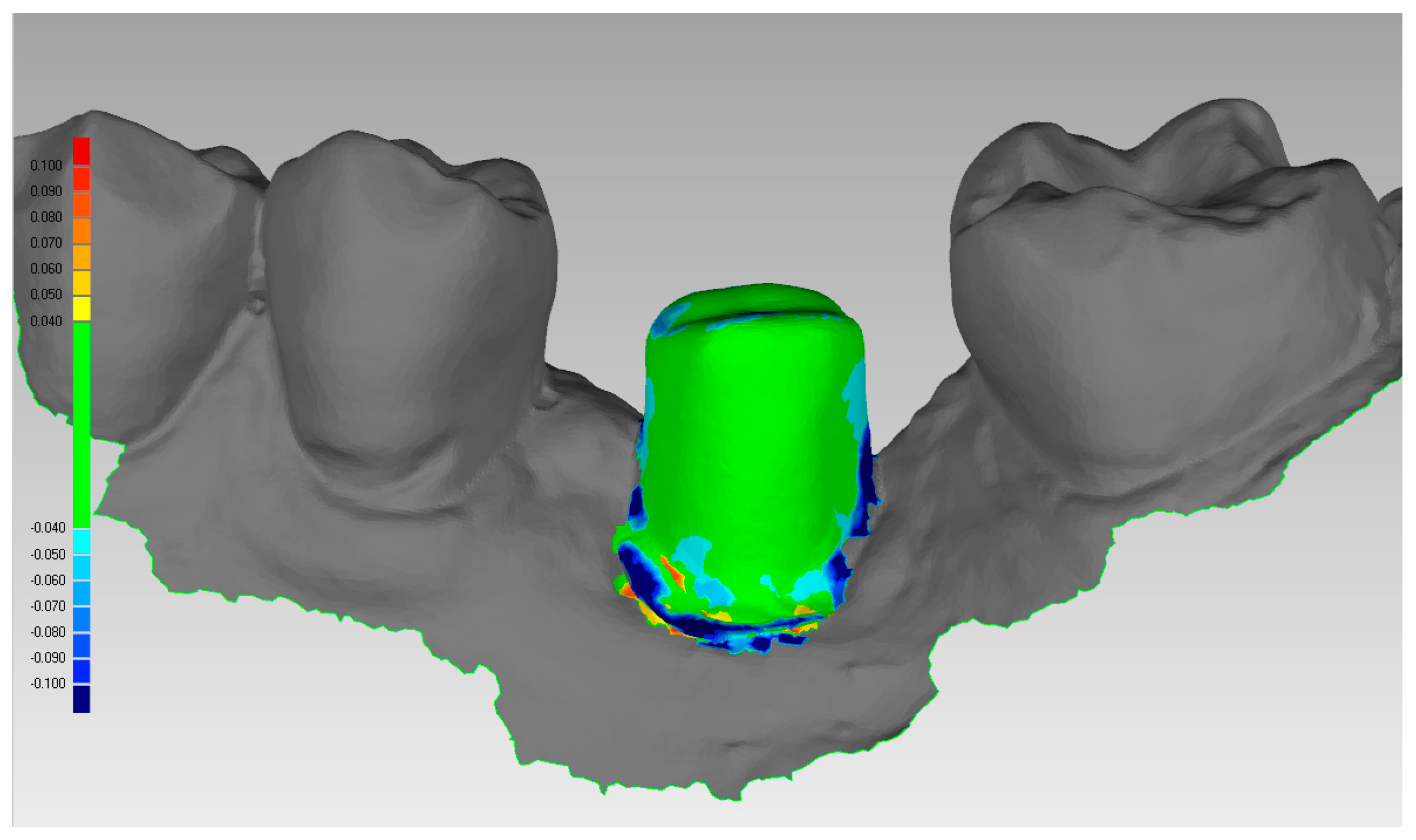
2.4.1. Marginal Adaptation of the Final Restoration
2.4.2. Quality of Occlusal and Interproximal Contact Points
2.4.3. Aesthetic Integration of the Final Crown
2.4.4. Survival of the Implant-Supported Restoration
2.4.5. Success of the Implant-Supported Restoration
2.5. Statistical Evaluation
3. Results
4. Discussion
5. Conclusions
Author Contributions
Funding
Acknowledgments
Conflicts of Interest
References
- Bohner, L.; Gamba, D.D.; Hanisch, M.; Marcio, B.S.; Tortamano Neto, P.; Laganá, D.C.; Sesma, N. Accuracy of digital technologies for the scanning of facial, skeletal, and intraoral tissues: A systematic review. J. Prosthet. Dent. 2018. [Google Scholar] [CrossRef] [PubMed]
- Mangano, F.; Gandolfi, A.; Luongo, G.; Logozzo, S. Intraoral scanners in dentistry: A review of the current literature. BMC Oral Health 2017, 17, 149. [Google Scholar] [CrossRef] [PubMed]
- Lanis, A.; Álvarez Del Canto, O. The combination of digital surface scanners and cone beam computed tomography technology for guided implant surgery using 3Shape implant studio software: A case history report. Int. J. Prosthodont. 2015, 28, 169–178. [Google Scholar] [CrossRef] [PubMed]
- Aragón, M.L.; Pontes, L.F.; Bichara, L.M.; Flores-Mir, C.; Normando, D. Validity and reliability of intraoral scanners compared to conventional gypsum models measurements: A systematic review. Eur. J. Orthod. 2016, 38, 429–434. [Google Scholar] [CrossRef] [PubMed]
- Abduo, J.; Elseyoufi, M. Accuracy of Intraoral Scanners: A Systematic Review of Influencing Factors. Eur. J. Prosthodont. Restor. Dent. 2018, 26, 101–121. [Google Scholar] [CrossRef] [PubMed]
- Burzynski, J.A.; Firestone, A.R.; Beck, F.M.; Fields, H.W., Jr.; Deguchi, T. Comparison of digital intraoral scanners and alginate impressions: Time and patient satisfaction. Am. J. Orthod. Dentofac. Orthop. 2018, 153, 534–541. [Google Scholar] [CrossRef]
- Mangano, A.; Beretta, M.; Luongo, G.; Mangano, C.; Mangano, F. Conventional Vs Digital Impressions: Acceptability, Treatment Comfort and Stress Among Young Orthodontic Patients. Open Dent. J. 2018, 12, 118–124. [Google Scholar] [CrossRef] [PubMed]
- Yuzbasioglu, E.; Kurt, H.; Turunc, R.; Bilir, H. Comparison of digital and conventional impression techniques: Evaluation of patients’ perception, treatment comfort, effectiveness and clinical outcomes. BMC Oral Health 2014, 14, 10. [Google Scholar] [CrossRef]
- Joda, T.; Brägger, U. Patient-centered outcomes comparing digital and conventional implant impression procedures: A randomized crossover trial. Clin. Oral Implants Res. 2016, 27, e185–e189. [Google Scholar] [CrossRef]
- Joda, T.; Lenherr, P.; Dedem, P.; Kovaltschuk, I.; Bragger, U.; Zitzmann, N.U. Time efficiency, difficulty, and operator’s preference comparing digital and conventional implant impressions: A randomized controlled trial. Clin. Oral Implants Res. 2017, 28, 1318–1323. [Google Scholar] [CrossRef]
- Albdour, E.A.; Shaheen, E.; Vranckx, M.; Mangano, F.G.; Politis, C.; Jacobs, R. A novel in vivo method to evaluate trueness of digital impressions. BMC Oral Health 2018, 18, 117. [Google Scholar] [CrossRef] [PubMed]
- Joda, T.; Zarone, F.; Ferrari, M. The complete digital workflow in fixed prosthodontics: A systematic review. BMC Oral Health 2017, 17, 124. [Google Scholar] [CrossRef] [PubMed]
- Joda, T.; Ferrari, M.; Brägger, U. Monolithic implant-supported lithium disilicate (LS2) crowns in a complete digital workflow: A prospective clinical trial with a 2-year follow-up. Clin Implant Dent. Relat. Res. 2017, 19, 505–511. [Google Scholar] [CrossRef] [PubMed] [Green Version]
- Mangano, F.; Veronesi, G. Digital versus Analog Procedures for the Prosthetic Restoration of Single Implants: A Randomized Controlled Trial with 1 Year of Follow-Up. BioMed Res. Int. 2018, 2018, 5325032. [Google Scholar] [CrossRef] [PubMed]
- Al Hamad, K.Q.; Al Rashdan, B.A.; Al Omari, W.M.; Baba, N.Z. Comparison of the Fit of Lithium Disilicate Crowns made from Conventional, Digital, or Conventional/Digital Techniques. J. Prosthodont. 2018. [Google Scholar] [CrossRef] [PubMed]
- Ueda, K.; Beuer, F.; Stimmelmayr, M.; Erdelt, K.; Keul, C.; Güth, J.F. Fit of 4-unit FDPs from CoCr and zirconia after conventional and digital impressions. Clin. Oral Investig. 2016, 20, 283–289. [Google Scholar] [CrossRef] [PubMed]
- Selz, C.F.; Bogler, J.; Vach, K.; Strub, J.R.; Guess, P.C. Veneered anatomically designed zirconia FDPs resulting from digital intraoral scans: Preliminary results of a prospective clinical study. J. Dent. 2015, 43, 1428–1435. [Google Scholar] [CrossRef]
- Zimmermann, M.; Koller, C.; Rumetsch, M.; Ender, A.; Mehl, A. Precision of guided scanning procedures for full-arch digital impressions in vivo. J. Orofac. Orthop. 2017, 78, 466–471. [Google Scholar] [CrossRef]
- Ahlholm, P.; Sipilä, K.; Vallittu, P.; Jakonen, M.; Kotiranta, U. Digital Versus Conventional Impressions in Fixed Prosthodontics: A Review. J. Prosthodont. 2018, 27, 35–41. [Google Scholar] [CrossRef]
- Goracci, C.; Franchi, L.; Vichi, A.; Ferrari, M. Accuracy, reliability, and efficiency of intraoral scanners for full-arch impressions: A systematic review of the clinical evidence. Eur. J. Orthod. 2016, 38, 422–428. [Google Scholar] [CrossRef]
- Khraishi, H.; Duane, B. Evidence for use of intraoral scanners under clinical conditions for obtaining full-arch digital impressions is insufficient. Evid. Based Dent. 2017, 18, 24–25. [Google Scholar] [CrossRef] [PubMed]
- Pietruski, J.K.; Skurska, A.; Bernaczyk, A.; Milewski, R.; Pietruska, M.J.; Gehrke, P.; Pietruska, M.D. Evaluation of concordance between CAD/CAM and clinical positions of abutment shoulder against mucosal margin: An observational study. BMC Oral Health 2018, 18, 73. [Google Scholar] [CrossRef] [PubMed]
- Imburgia, M.; Logozzo, S.; Hauschild, U.; Veronesi, G.; Mangano, C.; Mangano, F.G. Accuracy of four intraoral scanners in oral implantology: A comparative in vitro study. BMC Oral Health 2017, 17, 92. [Google Scholar] [CrossRef]
- Linkevicius, T.; Vaitelis, J. The effect of zirconia or titanium as abutment material on soft peri-implant tissues: A systematic review and meta-analysis. Clin. Oral Implants Res. 2015, 26 (Suppl. 11), 139–147. [Google Scholar] [CrossRef] [PubMed]
- Barwacz, C.A.; Stanford, C.M.; Diehl, U.A.; Cooper, L.F.; Feine, J.; McGuire, M.; Scheyer, E.T. Pink Esthetic Score Outcomes Around Three Implant-Abutment Configurations: 3-Year Results. Int. J. Oral Maxillofac. Implants 2018, 33, 1126–1135. [Google Scholar] [CrossRef] [PubMed]
- Hisbergues, M.; Vendeville, S.; Vendeville, P. Zirconia: Established facts and perspectives for a biomaterial in dental implantology. J. Biomed. Mater. Res. B Appl. Biomater. 2009, 88, 519–529. [Google Scholar] [CrossRef] [Green Version]
- Wittneben, J.G.; Gavric, J.; Belser, U.C.; Bornstein, M.M.; Joda, T.; Chappuis, V.; Sailer, I.; Brägger, U. Esthetic and Clinical Performance of Implant-Supported All-Ceramic Crowns Made with Prefabricated or CAD/CAM Zirconia Abutments: A Randomized, Multicenter Clinical Trial. J. Dent. Res. 2017, 96, 163–170. [Google Scholar] [CrossRef] [PubMed]
- Sivaraman, K.; Chopra, A.; Narayan, A.I.; Balakrishnan, D. Is zirconia a viable alternative to titanium for oral implant? A critical review. J. Prosthodont. Res. 2018, 62, 121–133. [Google Scholar] [CrossRef]
- Ferrari, M.; Carrabba, M.; Vichi, A.; Goracci, C.; Cagidiaco, M.C. Influence of Abutment Color and Mucosal Thickness on Soft Tissue Color. Int. J. Oral Maxillofac. Implants 2017, 32, 393–399. [Google Scholar] [CrossRef] [Green Version]
- Mangano, F.; Lucchina, A.G.; Brucoli, M.; Migliario, M.; Mortellaro, C.; Mangano, C. Prosthetic Complications Affecting Single-Tooth Morse-Taper Connection Implants. J. Craniofac. Surg. 2018, 29, 2255–2262. [Google Scholar] [CrossRef]
- Mangano, C.; Iaculli, F.; Piattelli, A.; Mangano, F. Fixed restorations supported by Morse-taper connection implants: A retrospective clinical study with 10–20 years of follow-up. Clin. Oral Implants Res. 2015, 26, 1229–1236. [Google Scholar] [CrossRef] [PubMed]
- Mangano, F.; Macchi, A.; Caprioglio, A.; Sammons, R.L.; Piattelli, A.; Mangano, C. Survival and complication rates of fixed restorations supported by locking-taper implants: A prospective study with 1 to 10 years of follow-up. J. Prosthodont. 2014, 23, 434–444. [Google Scholar] [CrossRef] [PubMed]
- Steiger-Ronay, V.; Merlini, A.; Wiedemeier, D.B.; Schmidlin, P.R.; Attin, T.; Sahrmann, P. Location of unaccessible implant surface areas during debridement in simulated peri-implantitis therapy. BMC Oral Health 2017, 17, 137. [Google Scholar] [CrossRef] [PubMed]
- Kato, A.; Imai, K.; Sato, H.; Ogata, Y. Prevalence of Epstein-Barr virus DNA and Porphyromonas gingivalis in Japanese peri-implantitis patients. BMC Oral Health 2017, 17, 148. [Google Scholar] [CrossRef] [PubMed] [Green Version]
- Salvi, G.E.; Brägger, U. Mechanical and technical risks in implant therapy. Int. J. Oral Maxillofac. Implants 2009, 24, 69–85. [Google Scholar]
- Mangano, F.G.; Veronesi, G.; Hauschild, U.; Mijiritsky, E.; Mangano, C. Trueness and Precision of Four Intraoral Scanners in Oral Implantology: A Comparative in Vitro Study. PLoS ONE 2016, 11, e0163107. [Google Scholar] [CrossRef] [PubMed]
- Mühlemann, S.; Greter, E.A.; Park, J.M.; Hämmerle, C.H.F.; Thoma, D.S. Precision of digital implant models compared to conventional implant models for posterior single implant crowns: A within-subject comparison. Clin. Oral Implants Res. 2018, 29, 931–936. [Google Scholar] [CrossRef] [PubMed]
- Abdel-Azim, T.; Rogers, K.; Elathamna, E.; Zandinejad, A.; Metz, M.; Morton, D. Comparison of the marginal fit of lithium disilicate crowns fabricated with CAD/CAM technology by using conventional impressions and two intraoral digital scanners. J. Prosthet. Dent. 2015, 114, 554–559. [Google Scholar] [CrossRef] [PubMed]
- Boeddinghaus, M.; Breloer, E.S.; Rehmann, P.; Wöstmann, B. Accuracy of single-tooth restorations based on intraoral digital and conventional impressions in patients. Clin. Oral Investig. 2015, 19, 2027–2034. [Google Scholar] [CrossRef] [PubMed]
- Roperto, R.; Assaf, H.; Soares-Porto, T.; Lang, L.; Teich, S. Are different generations of CAD/CAM milling machines capable to produce restorations with similar quality? J. Clin. Exp. Dent. 2016, 8, e423–e428. [Google Scholar] [CrossRef]
- Alharbi, N.; Wismeijer, D.; Osman, R.B. Additive Manufacturing Techniques in Prosthodontics: Where Do We Currently Stand? A Critical Review. Int. J. Prosthodont. 2017, 30, 474–484. [Google Scholar] [CrossRef] [PubMed] [Green Version]
- Mangano, C.; Mangano, F.; Shibli, J.A.; Tettamanti, L.; Figliuzzi, M.; d’Avila, S.; Sammons, R.L.; Piattelli, A. Prospective evaluation of 2549 Morse taper connection implants: 1- to 6-year data. J. Periodontol. 2011, 82, 52–61. [Google Scholar] [CrossRef] [PubMed]
- Mangano, F.; Shibli, J.A.; Sammons, R.L.; Veronesi, G.; Piattelli, A.; Mangano, C. Clinical outcome of narrow-diameter (3.3-mm) locking-taper implants: A prospective study with 1 to 10 years of follow-up. Int. J. Oral Maxillofac. Implants 2014, 29, 448–455. [Google Scholar] [CrossRef] [PubMed]
- Mangano, F.; Frezzato, I.; Frezzato, A.; Veronesi, G.; Mortellaro, C.; Mangano, C. The Effect of Crown-to-Implant Ratio on the Clinical Performance of Extra-Short Locking-Taper Implants. J. Craniofac. Surg. 2016, 27, 675–681. [Google Scholar] [CrossRef] [PubMed]
- Canullo, L.; Pesce, P.; Tronchi, M.; Fiorellini, J.; Amari, Y.; Penarrocha, D. Marginal soft tissue stability around conical abutments inserted with the one abutment-one time protocol after 5 years of prosthetic loading. Clin Implant Dent. Relat. Res. 2018. [Google Scholar] [CrossRef] [PubMed]
- Mangano, F.G.; Hauschild, U.; Admakin, O. Full in-Office Guided Surgery with Open Selective Tooth-Supported Templates: A Prospective Clinical Study on 20 Patients. Int. J. Environ. Res. Public Health 2018, 15, 2361. [Google Scholar] [CrossRef] [PubMed]
- Konstantinidis, I.; Trikka, D.; Gasparatos, S.; Mitsias, M.E. Clinical Outcomes of Monolithic Zirconia Crowns with CAD/CAM Technology. A 1-Year Follow-Up Prospective Clinical Study of 65 Patients. Int. J. Environ. Res. Public Health 2018, 15, 2523. [Google Scholar] [CrossRef]
- Sarıkaya, I.; Hayran, Y. Effects of dynamic aging on the wear and fracture strength of monolithic zirconia restorations. BMC Oral Health 2018, 18, 146. [Google Scholar] [CrossRef]


| Type of Issue | Incidence | Complication Rate % |
|---|---|---|
| Marginal adaptation (MA) | 0/40 crowns | 0% |
| Occlusal adaptation (OA) | 2/40 crowns | 5% |
| Interproximal adaptation (IA) | 1/40 crowns | 2.5% |
| Aesthetic integration (iE) | 1/40 crowns | 2.5% |
| Total | 4/40 crowns | 10% |
| N° | Failures | Survival Rate % | Complications | Success Rate % | |
|---|---|---|---|---|---|
| Gender | |||||
| Male | 12 | 1/12 | 91.7% | 1/11 ZCD | 91.0% |
| Female | 13 | 0/13 | 100% | 1/13 HALC 11/13 ZAD | 84.7% |
| Smoke | |||||
| Yes | 6 | 1/6 | 83.4% | 0/5 | 100% |
| No | 19 | 0/19 | 100% | 1/19 ZCD 1/19 HALC 1/19 ZAD | 84.3% |
| Location | |||||
| Maxilla | 25 | 1/25 | 96% | 1/24 ZCD 1/24 HALC | 91.7% |
| Mandible | 15 | 0/15 | 100% | 1/15 ZAD | 93.4% |
| Position | |||||
| Premolar | 12 | 0/12 | 100% | 1/12 ZAD | 91.7% |
| Molar | 28 | 1/28 | 96.5% | 1/27 HALC 1/27 ZCD | 92.6% |
| Titanium base | |||||
| Tibase® | 8 | 0/8 | 100% | 1/8 HALC 1/8 ZAD | 75% |
| Multitech straight® | 10 | 0/10 | 100% | 0/10 | 100% |
| Multitech angled® | 12 | 1/12 | 91.7% | 1/11 ZCD | 91% |
| Implant diameter | |||||
| 3.3 mm | 1 | 0/1 | 100% | 0/1 | 100% |
| 4.1 mm | 15 | 0/15 | 100% | 1/15 HALC | 93.4% |
| 4.8 mm | 20 | 0/20 | 100% | 1/20 ZAD 1/20 ZCD | 90% |
| 5.5 mm | 4 | 1/4 | 75% | 0/3 | 100% |
| Implant length | |||||
| 6.5 mm | 4 | 1/4 | 75% | 0/3 | 100% |
| 8 mm | 10 | 0/10 | 100% | 1/10 ZCD | 90% |
| 10 mm | 14 | 0/!4 | 100% | 1/14 HALC | 92.9% |
| 12 mm | 8 | 0/8 | 100% | 1/8 ZAD | 87.5% |
| 14 mm | 4 | 0/4 | 100% | 0/4 | 100% |
| Total | 40 | 1/40 | 97.5% | 3/39 | 92.4% |
© 2019 by the authors. Licensee MDPI, Basel, Switzerland. This article is an open access article distributed under the terms and conditions of the Creative Commons Attribution (CC BY) license (http://creativecommons.org/licenses/by/4.0/).
Share and Cite
Mangano, F.; Margiani, B.; Admakin, O. A Novel Full-Digital Protocol (SCAN-PLAN-MAKE-DONE®) for the Design and Fabrication of Implant-Supported Monolithic Translucent Zirconia Crowns Cemented on Customized Hybrid Abutments: A Retrospective Clinical Study on 25 Patients. Int. J. Environ. Res. Public Health 2019, 16, 317. https://0-doi-org.brum.beds.ac.uk/10.3390/ijerph16030317
Mangano F, Margiani B, Admakin O. A Novel Full-Digital Protocol (SCAN-PLAN-MAKE-DONE®) for the Design and Fabrication of Implant-Supported Monolithic Translucent Zirconia Crowns Cemented on Customized Hybrid Abutments: A Retrospective Clinical Study on 25 Patients. International Journal of Environmental Research and Public Health. 2019; 16(3):317. https://0-doi-org.brum.beds.ac.uk/10.3390/ijerph16030317
Chicago/Turabian StyleMangano, Francesco, Bidzina Margiani, and Oleg Admakin. 2019. "A Novel Full-Digital Protocol (SCAN-PLAN-MAKE-DONE®) for the Design and Fabrication of Implant-Supported Monolithic Translucent Zirconia Crowns Cemented on Customized Hybrid Abutments: A Retrospective Clinical Study on 25 Patients" International Journal of Environmental Research and Public Health 16, no. 3: 317. https://0-doi-org.brum.beds.ac.uk/10.3390/ijerph16030317