A System-Level Modelling of Noise in Coupled Resonating MEMS Sensors †


Independent scientific consultant and a researcher, 4000 Liège, Belgium
†
Presented at the 1st International Electronic Conference—Futuristic Applications on Electronics, 1–30 November 2020; Available online: https://iec2020.sciforum.net/.
Eng. Proc. 2020, 3(1), 5; https://0-doi-org.brum.beds.ac.uk/10.3390/IEC2020-06971
Published: 30 October 2020
(This article belongs to the Proceedings of 1st International Electronic Conference—Futuristic Applications on Electronics)
Abstract
:This paper presents realistic system-level modeling of effective noise sources in a coupled resonating mode-localized MEMS sensors. A governing set of differential equations are used to build a numerical model of a mechanical noise source in a coupled-resonator sensor and an effective thermo-mechanical noise is quantified through the simulation performed via SIMULINK. On a similar note, an effective noise that stems from the electronic readout used for the coupled resonating MEMS sensors is also quantified. Various noise sources in electronic readout are identified and the contribution of each is quantified. A comparison between an effective mechanical and electronic noise in a sensor system aids in identifying the dominant noise source in a sensor system. A method to optimize the system noise floor for an amplitude-based readout is presented. The proposed models present a variety of operating conditions, such as finite quality factor, varying coupled electrostatic spring strength, and operation with in-phase and out-of-phase mode. The proposed models aim to study the impact of fundamental noise processes that govern the ultimate resolution into a coupled resonating system used for various sensing applications.
1. Introduction
In a typical MEMS resonator system, electronic circuits (typically a current to voltage converter also called trans-impedance amplifier) is used for readout and processing of the electrical signal (output motional current from a resonator) provided by the sensing element. A total noise level of the system is therefore due to the combined effect of the mechanical–thermal noise in the mechanical domain, the electrical noise of the (resistive) mechanical sensing element [1] and the input-referred noise of the readout circuits [1,2,3,4]. In a MEMS sensor system, noise from a readout circuit dominates the noise performance [5]. However, the details of the mechanical–thermal noise should also be considered relevant, and a noise source (mechanical or electronic) that determines the detection limit of the sensor should be analyzed.
In this paper, an attempt is made to model and quantify an effective noise into the two coupled-resonator (WCR) system used for sensing applications. Through mathematical analysis and simulations obtained via the Simulink model, a source of the dominant noise source is identified.An effective noise floor in the design is quantified. Following this, the finest possible resolution for the design is proposed.
2. Noise Floor in a Coupled Resonator Sensor
In order to understand the impact of system noise on the performance of a coupled-resonator (CR) sensor, a noise source was added to the model. Output response was analyzed to determine the ultimate detection limit, i.e., resolution of a CR sensor.
Thermo-Mechanical Noise in CR Sensor Design
In this section, a model to quantify a magnitude of a thermal-mechanical noise is presented. Small moving parts in MEMS are especially susceptible to mechanical noise resulting from molecular agitation [1]. In ultra-low level signal detection, mechanical-thermal noise plays an important role in setting up the effective noise floor of a sensor system, and, thus a minimum detection limit. In the context of a CR sensor, it has been concluded that it is the thermal-mechanical noise that governs the ultimate detection limit of a CR sensor [2]. In this paper, a mechanical-thermal noise source in 2 DoF CR sensor is modeled and its impact on the resolution (i.e., lowest possible detectable physical quantity) is quantified for the amplitude-based output of the design.
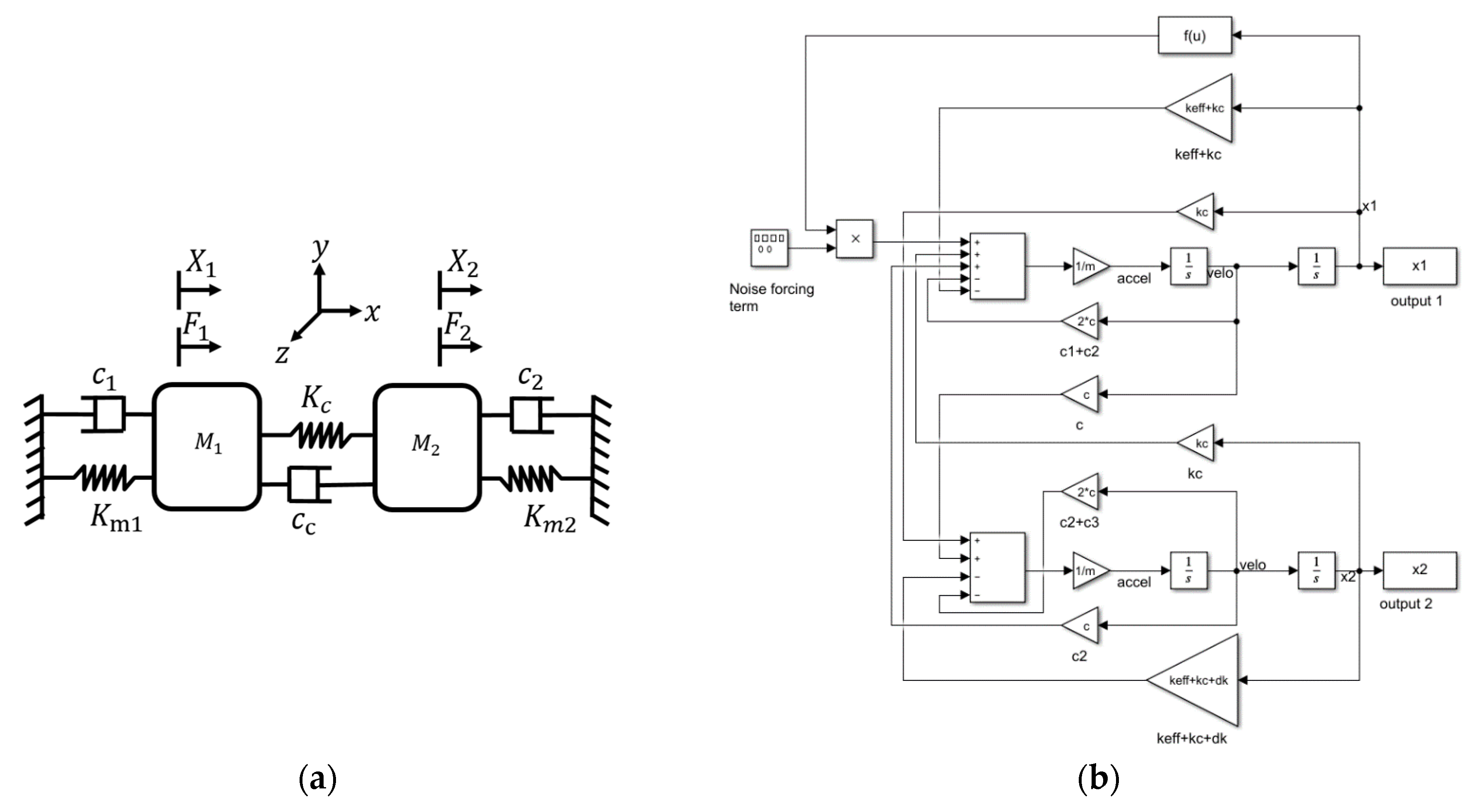
Consider a schematic representation of a 2-DoF CR sensor system as shown in Figure 1a. It consists of effective mass, Mi, spring constant, Ki and damping constant, ci, (i = 1, 2). A coupling spring, Kc and damping constant, cc that may exist between the two resonators are also shown. Design conditions are: M1 = M2 = M, Km1 = Km2 = Km, c1 = c2 = cc = c and Kc << Km. In the design, it is stated that Xji is the amplitude variations of a j-th resonator (j = 1, 2) at the i-th mode of frequency response (i = 1, 2) due to the noise-induced into the system. Therefore, an expression of the output/s (considering a system involving an intrinsic (mechanical) and extrinsic (electronic) noise sources) may be obtained as follows: (i) a minimum resolvable amplitude ratio (AR) shift is and (ii) a minimum resolvable amplitude shift is . A power spectral density (PSD) of an amplitude displacement noise of j-th resonator (j = 1, 2) at the i-th mode of the frequency response (i = 1, 2) can be investigated (through the Simulink model). An effect of a mechanical noise was modeled by adding a force term into the governing set of equations of motion (for 2 DoF) as follows
A spectral density of a noise forcing term is given as N/Hz0.5 [1,5]. Here, kB is the Boltzmann constant (≈1.380 × 10⁻²³ Joule/Kelvin), T is the temperature (300 Kelvin) and c is the damping coefficient (c = 0.0031 Ns/m in our case). As observed, the spectral density of a mechanical noise force depends on temperature and the magnitude of mechanical damping. A noise forcing term with the calculated average value, 5.136 × 10⁻²² N2 was added as an excitation force into the Simulink model shown in Figure 1b.
3. Results
A noise PSD (in dB/Hz) for displacements X1 and X2 was plotted as shown in Figure 2. Simulations were run for the varying strength of a coupling spring, Kc between the two resonators in our design. Condition for the simulation are as follows: c = 0.0031 Ns/m, (Q ≈ 2547), ∆k = 0, κ = −0.0032, excitation force applied to mass M1. ∆k is the perturbation into the stiffness of one of the resonators in 2-DoF CR sensor system.
A resultant displacement noise PSD (due to noise forcing term) is −582.2 dB/Hz (at mode 1) and −572.2 dB/Hz (at mode 2) (refer to Figure 2a) which correspond to an equivalent magnitude of 7.76 × 10⁻³⁰ m2/Hz (at mode 1) and 2.45 × 10⁻²⁹ m2/Hz (at mode 2) respectively. Assuming a measurement bandwidth of 10 Hz around the resonant mode frequencies, ωi (i = 1, 2), an average value of a mechanical thermal noise of jth resonator at the ith mode (j, i = 1, 2) can be computed as (refer Table A1). All tables are placed in the appendix section.
Theoretical estimation of effective noise current for our design (due to intrinsic mechanical-thermal noise) is given as , where, , and Xji are transduction factor, angular frequency and the maximum displacement amplitude of the jth resonator (j = 1, 2) at the ith mode of the frequency response (i = 1, 2), respectively [6]. By determining the the effective mechanical-thermal noise current (i.e., corresponding variations in the motional currents, due to noise forcing term) was quantified (refer Table A1). Since the thermal noise amplitude of mode 1 is relatively lower (refer to Figure 2), the computation for the best case is given.
3.1. Modelling the Noise from the Electronic Readout
Figure 3a represents the schematic representation of transimpedance amplifier that may be realized using OPA 381 [7] integrated circuit (IC) as an interface circuit to the CR design. Two such ICs may be deployed for motional current pick-up into each output channel of the CR output. Figure 3b is the equivalent noise model for the interface circuit used (transimpedance amplifier). A noise contribution from each of these sources is estimated by superposition and nodal analysis.
An amplifier (OPA 381) [7] used in the analysis has an input current noise density, in ≈ 20 fA/Hz0.5, and an input voltage noise density, vn ≈ 70 nV/Hz0.5. In a CR sensor system, in the presence of an applied ac signal vac, an impact of noise on the motional current output of j-th resonator (j = 1, 2) at the i-th mode of response (i = 1, 2) can be evaluated (refer Figure 1b). This ac voltage signal together with the DC voltage, Vdc exerts a net electrostatic actuation force at the resonant frequency. In order to evaluate the impact of the electronic preamplifier (OPA 381) noise on the minimum shifts into the amplitude-based output/s (and thus quantify measurand, ∆k or (normalized)), all noise components were re-expressed as equivalent current as given in Table A2. In Table A2, (rms) is the noise current from the j-th resonator at the i-th mode of response. Rx is the motional resistance, [8] (Rx = 4 MΩ for a Q ≈ 2547 with other parameters being constant, in our case), Rf is the effective value of a feedback resistor used in the preamplifier (1 MΩ). The term kB is the Boltzmann constant (≈1.380 × 10⁻²³ Joule/Kelvin) and T is the temperature (300 Kelvin). Term B is the integration bandwidth of 10 Hz around the resonator’s mode frequencies, f_ip and f_op) taken for computations for optimum noise estimation. From Table A2, an effective theoretical noise floor (i.e., input-referred electronic noise current, due to electronic readout) of our design is ≈1.56 × 10⁻¹³ Arms. A total noise (mechanical resonator + electronics) in our design is then estimated by the vector sum of the uncorrelated noise sources i.e., It2 = I12 + I22, where, I1 is effective mechanical noise current and I2 is effective electronic readout noise current. It is calculated to be ≈1.56 × 10⁻¹³ Arms.
An electrostatic forcing term was applied to the Simulink model shown in Figure 1b. An effective system noise was added to the Simulink model. Other model conditions are the same as given in Figure 2. As a result, the following computations are obtained (refer to Table A3). Calculated values for motional current amplitudes are in agreement with the simulated values.
3.2. Resolving the Lowest Possible Shifts (i.e., Resolution)
The minimum resolvable shift in the voltage amplitudes of our 2-DoF CR sensor was derived as [6]. Here, is the output refereed noise voltage of the j-th coupled-resonator at the i-th mode. is the noiseless deterministic output voltages (determined as , where, ). Therefore, for the j-th resonator lowest possible resolvable mode amplitude shift, is , (dimensionless) for mode 1, and is (dimensionless) for mode 2. Similarly, the minimum resolvable shift in the amplitude ratio readout, ARi at the i-th mode (i = 1, 2) is (dimensionless) for mode 1 and (dimensionless) for mode 2. Since rms amplitudes of output voltage (essentially a motional current) at the mode 1 for j-th resonator is relatively closer (worst-case signal-to-noise (S/N) ratio) to the rms noise amplitude, it gives the possibility to determine the worst-case lowest possible shift (thus resolution) in the design. The effective resolution (theoretical) of our design for AR-based readout is ≈3.89 × 10⁻⁷ which may be compared to the theoretically calculated resolution (≈6 × 10⁻³) in MEMS coupled-resonator design in [6].
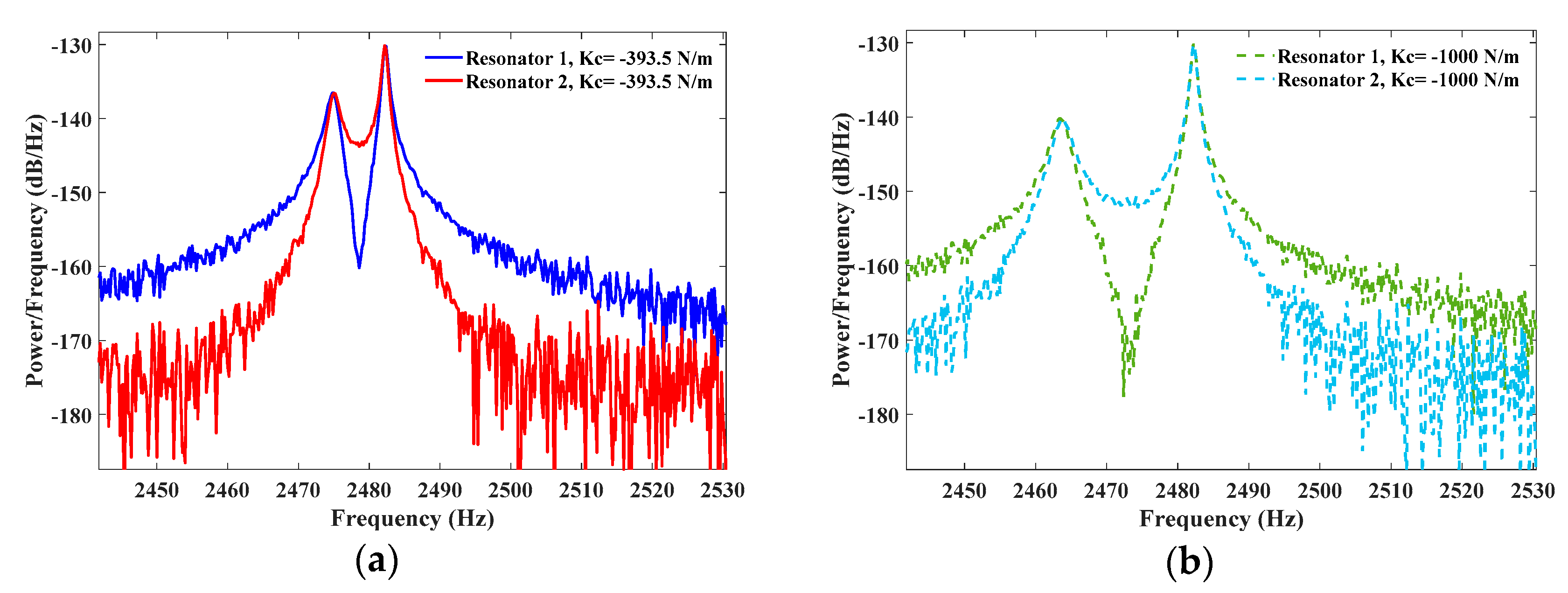
3.3. Influence of Coupling Strength on the Effective Noise Floor
This section shows if electrostatic spring strength, Kc, coupling the two resonators influence the effective noise floor. Figure 4 shows a simulated frequency spectrum of the j-th resonator (j = 1, 2) resonators for two variants of coupling spring, Kc. As observed, with the given set of operating conditions, the output signal from resonator 2 offers a relatively lower noise floor as compared to resonator 1 and is independent of the coupling strength (refer to Figure 4a,b). In addition, it is useful to utilize the output of the j-th resonator at mode 2 as it offers a higher amplitude and thus maximum shifts (sensitivity). From Figure 4, it is inferred that smaller coupling strength, Kc leads to reduced noise floor (about −12 dB gain in the noise floor thus enhancing the ultimate detection limit of the measurand) for the resonating output of the resonator 2.
4. Discussion and Conclusions
This work attempted to model and quantify the noise in the design of a 2-DoF MEMS CR sensor. An expected variation in the sensor output arising from the intrinsic (mechanical) and extrinsic (electronic) noise sources were individually evaluated via theory and system-level simulations. From Table A2, it is seen that though mechanical-thermal noise sets the ultimate noise floor in this design, it is an electronic noise that dominates the overall performance (electronics noise exceeds mechanical noise by two orders of magnitude). Through quantifying the system noise in the system, a system-level model aids in simulating the sensor output response. The ultimate detection limit in the 2-DoF CR sensor design is determined. A method to optimize the system noise/improve detection limit is also proposed (via tuning the coupling spring).
Appendix A

Table A1.
Table showing the computation of the effective noise forcing term, displacement noise amplitudes and the resultant noise current due to the mechanical noise forcing term.
Table A1.
Table showing the computation of the effective noise forcing term, displacement noise amplitudes and the resultant noise current due to the mechanical noise forcing term.
| Term | Value | Expression |
|---|---|---|
| 1 | ||
| 2 | ||
| 3 | ||
| * | ||
| ** | ||
| *** |
1 A best-case estimate for average noise power for mode 1. 2 An effective rms value of a mechanical-thermal noise for mode 1. 3 An effective noise current due to the mechanical noise forcing term. * Power spectral density (PSD) of mechanical noise force generator. ** Average (mean square) value of a mechanical thermal noise force generator, assumed measurement bandwidth is 10 Hz. *** A effective rms amplitude of mechanical noise forcing term (mean square) value of mechanical thermal noise of j-th resonator at the i-th mode (j, i = 1, 2) will be . Refer Table A1 for the computations. As observed from Figure 2, noise magnitude is lower for mode 1.
Table A2.
Table showing the contribution of the noise current due to the several noise terms used in the electronic readout for the mechanical CR sensor.
Table A2.
Table showing the contribution of the noise current due to the several noise terms used in the electronic readout for the mechanical CR sensor.
| Noise Sources | Effective Noise Current (Arms) | Expression |
|---|---|---|
| Mechanical thermal-noise 1 | 4.9 × 10⁻¹⁵ | |
| Feedback resistance | 4.06 × 10⁻¹³ | |
| Input voltage noise of a pre-amplifier | 4.34 × 10⁻¹³ | |
| Input current noise of a pre-amplifier 2 | 9.92 × 10⁻¹⁴ | |
| input-referred electronic noise current, | 1.56 × 10⁻¹³ Arms | |
| Total system noise (mechanical + electronic) | ≈1.56 × 10⁻¹³ Arms | It2 = I12 + I22 |
1 Best-case calculation for the out-of-phase mode as it shows the lower noise amplitude. 2 Factor 1.57 is the roll-off rate of a filter (1-pole) [9].
Table A3.
Computations and simulated results in response to the electrostatic forcing term used in the Simulink model. Noise due to mechanical and electronic terms was taken into account to simulate the output response.
Table A3.
Computations and simulated results in response to the electrostatic forcing term used in the Simulink model. Noise due to mechanical and electronic terms was taken into account to simulate the output response.
| Term | Value (Mode 1) | Value (Mode 2) | Expression |
|---|---|---|---|
| maximum displacement 1, | xj1 ≈ 0.419 µm | xj2 ≈ 0.836 µm | N/A |
| motional current amplitudes 2, | ≈ 192 nA | ≈ 384 nA | , |
| Effective output voltage 3, | = 0.135 Vrms | = 0.271 Vrms | , |
| output referred noise voltage 2, | ≈156 × 10−9 Vrms | N/A | × Rf |
| lowest possible resolvable mode amplitude shift, | (dimensionless) | (dimensionless) | , |
| minimum resolvable shift in the amplitude ratio readout, ARi | (dimensionless) | (dimensionless) | , |
1 Derived from the Simulink. 2 Theory. 3 Amplification factor, Rf = 1 MΩ, as a feedback resistor in preamplifier OPA 381.
References
- Gabrielson, T.B. Mechanical-Thermal Noise in Micromachined Acoustic and Vibration Sensors. IEEE Trans. Electron. Devices 1993, 40, 903–909. [Google Scholar] [CrossRef]
- Juillard, J.; Prache, P.; Ferreira, P.M.; Barniol, N. Ultimate limits of differential resonant MEMS sensors based on two coupled linear resonators. IEEE Trans. Ultrason. Ferroelectr. Freq. Control 2018, 65, 2440–2448. [Google Scholar] [CrossRef] [PubMed]
- Juillard, J.; Prache, P.; Ferreira, P.M.; Barniol, N. Impact of output metric on the resolution of mode-localized MEMS resonant sensors. In Proceedings of the 2017 Joint Conference of the European Frequency and Time Forum and IEEE International Frequency Control Symposium (EFTF/IFCS), Besancon, France, 9–13 July 2017. [Google Scholar] [CrossRef]
- Pandit, M.; Zhao, C.; Sobreviela, G.; Mustafazade, A.; Du, S.; Zou, X.; Seshia, A.A. Closed-Loop Characterization of Noise and Stability in a Mode-Localized Resonant MEMS Sensor. IEEE Trans. Ultrason. Ferroelectr. Freq. Control 2019. [Google Scholar] [CrossRef] [PubMed]
- Djurić, Z. Mechanisms of noise sources in microelectromechanical systems. Microelectron. Reliab. 2002, 40, 919–932. [Google Scholar] [CrossRef]
- Thiruvenkatanathan, P.; Woodhouse, J.; Yan, J.; Seshia, A.A. Limits to mode-localized sensing using micro- and nanomechanical resonator arrays. J. Appl. Phys. 2011, 109, 104903. [Google Scholar] [CrossRef]
- Precision, Low Power, 18 MHz Transimpedance Amplifier. Available online: www.ti.com (accessed on 23 June 2019).
- Hung, L.; Nguyen, C. High-Q Low-Impedance MEMS Resonators; Technical Report No. UCB/EECS-2012-218; University of California: Berkeley, CA, USA, December 2012. [Google Scholar]
- TI Precision Labs—Op Amps: Noise 1|TI.com Video. Available online: https://training.ti.com/ti-precision-labs-op-amps-noise-1 (accessed on 23 June 2019).
Figure 1.
(a) Schematic representation of a 2-DoF coupled-resonator (CR) sensor system. Proof mass, Mi, springs, Ki and dampers, ci (i = 1, 2) are shown (b) Simulink block diagram representing the system-level model.
Figure 1.
(a) Schematic representation of a 2-DoF coupled-resonator (CR) sensor system. Proof mass, Mi, springs, Ki and dampers, ci (i = 1, 2) are shown (b) Simulink block diagram representing the system-level model.

Figure 2.
Simulated power spectrum density (PSD) of a displacement noise of resonator 1 and 2 subject to mechanical-thermal noise forcing term on resonator 1. (a) Kc = −393.5 N/m and (b) Kc = −1000 N/m. Simulation conditions are as follows: c = 0.0031 Ns/m, (Q ≈ 2547), ∆k = 0, excitation force applied to mass M1. A normalized coupling factor, κ is given by Kc/Keff. ∆k is the induced perturbation into the stiffness of one of the resonators in a 2-DoF CR sensor system.

Figure 3.
(a) OPA 381 interface for a 2-DoF CR sensor design (b) equivalent noise circuit to evaluate circuit dominant noise.
Figure 3.
(a) OPA 381 interface for a 2-DoF CR sensor design (b) equivalent noise circuit to evaluate circuit dominant noise.

Figure 4.
Simulated PSD of the motional current output signal in two weakly coupled-resonators for the following operating condition, Q = 2547, δk = 0, F = 1 N.
Figure 4.
Simulated PSD of the motional current output signal in two weakly coupled-resonators for the following operating condition, Q = 2547, δk = 0, F = 1 N.

Publisher’s Note: MDPI stays neutral with regard to jurisdictional claims in published maps and institutional affiliations. |
© 2020 by the author. Licensee MDPI, Basel, Switzerland. This article is an open access article distributed under the terms and conditions of the Creative Commons Attribution (CC BY) license (https://creativecommons.org/licenses/by/4.0/).
Share and Cite
MDPI and ACS Style
Pachkawade, V. A System-Level Modelling of Noise in Coupled Resonating MEMS Sensors. Eng. Proc. 2020, 3, 5. https://0-doi-org.brum.beds.ac.uk/10.3390/IEC2020-06971
AMA Style
Pachkawade V. A System-Level Modelling of Noise in Coupled Resonating MEMS Sensors. Engineering Proceedings. 2020; 3(1):5. https://0-doi-org.brum.beds.ac.uk/10.3390/IEC2020-06971
Chicago/Turabian StylePachkawade, Vinayak. 2020. "A System-Level Modelling of Noise in Coupled Resonating MEMS Sensors" Engineering Proceedings 3, no. 1: 5. https://0-doi-org.brum.beds.ac.uk/10.3390/IEC2020-06971