Constructing Minimally 3-Connected Graphs


1
Departamento de Matemática, Universidade Federal Do Espírito, Vitória 29075-910, Brazil
2
Bloomberg LP, New York, NY 10165, USA
3
Department of Mathematics, Brooklyn College, City University of New York, Brooklyn, NY 11210, USA
*
Author to whom correspondence should be addressed.
†
These authors contributed equally to this work.
Algorithms 2021, 14(1), 9; https://0-doi-org.brum.beds.ac.uk/10.3390/a14010009
Submission received: 1 December 2020
/
Revised: 22 December 2020
/
Accepted: 28 December 2020
/
Published: 1 January 2021
(This article belongs to the Special Issue Selected Algorithmic Papers From CSR 2020)
Abstract
:A 3-connected graph is minimally 3-connected if removal of any edge destroys 3-connectivity. We present an algorithm for constructing minimally 3-connected graphs based on the results in (Dawes, JCTB 40, 159-168, 1986) using two operations: adding an edge between non-adjacent vertices and splitting a vertex. To test sets of vertices and edges for 3-compatibility, which depends on the cycles of the graph, we develop a method for obtaining the cycles of from the cycles of G, where is obtained from G by one of the two operations above. We eliminate isomorphic duplicates using certificates generated by McKay’s isomorphism checker nauty. The algorithm consecutively constructs the non-isomorphic minimally 3-connected graphs with n vertices and m edges from the non-isomorphic minimally 3-connected graphs with vertices and edges, vertices and edges, and vertices and edges.
1. Introduction
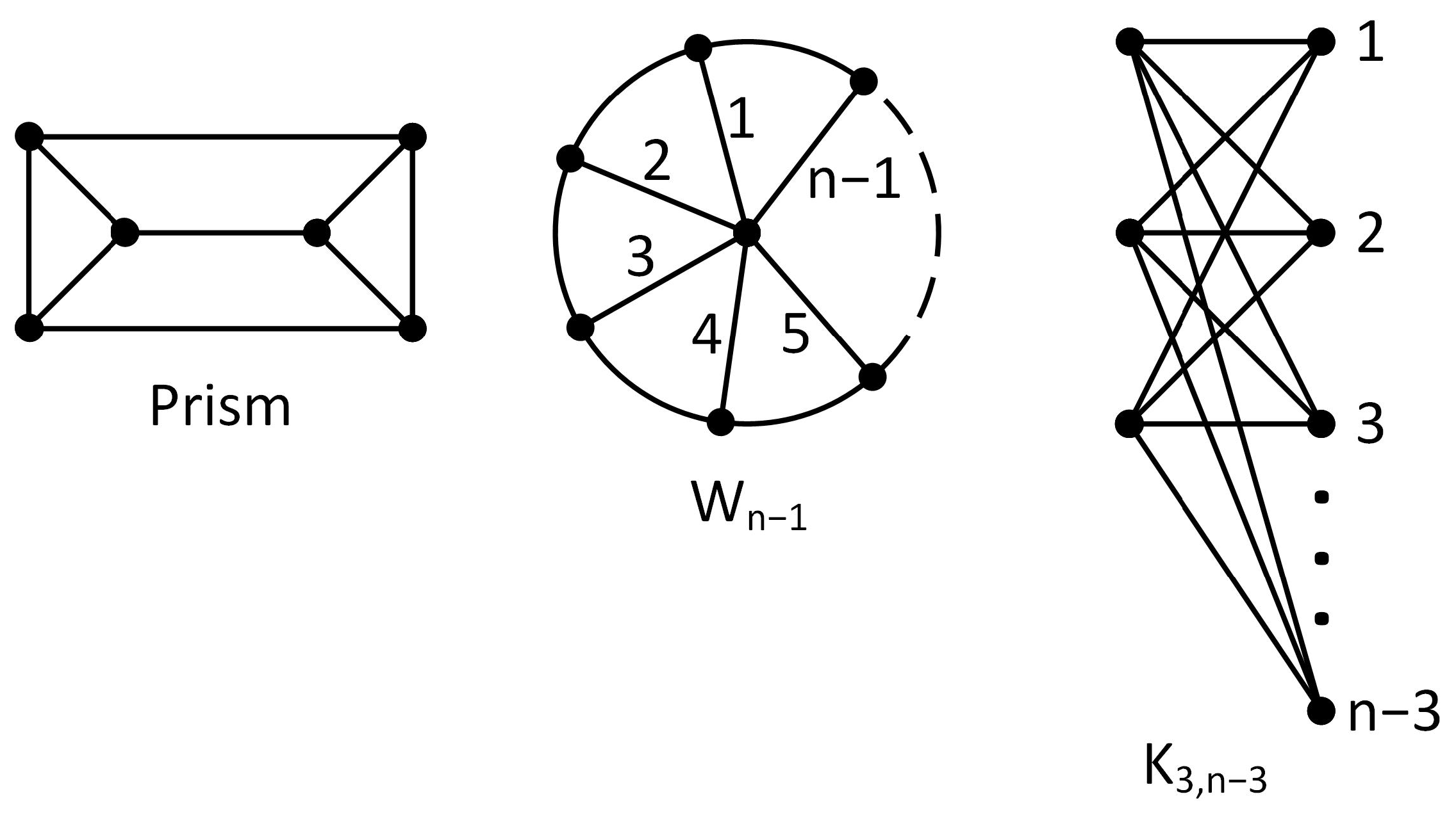
In this paper, we present an algorithm for consecutively generating minimally 3-connected graphs, beginning with the prism graph, with the exception of two families. The two exceptional families are the wheel graph with n vertices and spokes denoted by for and the complete bipartite graph with 3 vertices in one class and vertices in the other class denoted by for . See Figure 1.
Tutte proved that a simple graph is 3-connected if and only if it is a wheel or is obtained from a wheel by adding edges between non-adjacent vertices and splitting vertices [1]. The vertex split operation is illustrated in Figure 2. At each stage the graph obtained is 3-connected.
A cubic graph is a graph whose vertices have degree 3. Let G and H be 3-connected cubic graphs such that and H is a minor of G. A pair of distinct edges is bridged if they are subdivided by vertices x and y, respectively, forming paths of length 2, and x and y are joined by an edge. This operation is explained in detail in Section 2 and illustrated in Figure 3. Tutte also proved that G can be obtained from H by repeatedly bridging edges. At each stage the graph obtained remains 3-connected and cubic [2]. Observe that this operation is equivalent to adding an edge to a cubic graph and splitting u and splitting v. This gives an easy way of consecutively constructing all 3-connected cubic graphs on n vertices for even n. Surprisingly the entry for the number of 3-connected cubic graphs in the Online Encyclopedia of Integer Sequences (sequence A204198) has entries only up to . We were able to quickly obtain such graphs up to .
Tutte’s result and our algorithm based on it suggested that a similar result and algorithm may be obtainable for the much larger class of minimally 3-connected graphs.
Dawes gave a necessary and sufficient characterization for the construction of minimally 3-connected graphs starting with . To do this he needed three operations one of which is the above operation where two distinct edges are bridged. Let be an edge and be a vertex. A vertex and an edge are bridged if a new vertex is placed on edge e and linked to x. Dawes proved that starting with the class of minimally 3-connected graphs can be constructed by bridging a vertex and an edge, bridging two edges, or by adding a degree 3 vertex in the manner Dawes specified using what he called “3-compatible sets” as explained in Section 2. Following the above approach for cubic graphs we were able to translate Dawes’ operations to edge additions and vertex splits and develop an algorithm that consecutively constructs minimally 3-connected graphs from smaller minimally 3-connected graphs.
First, we prove exactly how Dawes’ operations can be translated to edge additions and vertex splits. Second, we prove a cycle propagation result. Although obtaining the set of cycles of a graph is NP-complete in general, we can take advantage of the fact that we are beginning with a fixed cubic initial graph, the prism graph. We develop methods for constructing the set of cycles for a graph obtained from a graph G by edge additions and vertex splits, and Dawes specifications on 3-compatible sets. Let n be the number of vertices in G and let c be the number of cycles of G. We prove that the set of cycles of can be obtained from the set of cycles of G by a method with complexity . Third, we prove that if G is a minimally 3-connected graph that is not for or for , then G must have a prism minor, for , and G can be obtained from a smaller minimally 3-connected graph such that using edge additions and vertex splits and Dawes specifications on 3-compatible sets.
We present an algorithm based on the above results that consecutively constructs the non-isomorphic minimally 3-connected graphs with n vertices and m edges from the non-isomorphic minimally 3-connected graphs with vertices and edges, vertices and edges, and vertices and edges. This formulation also allows us to determine worst-case complexity for processing a single graph; namely , which includes the complexity of cycle propagation mentioned above.
There has been a significant amount of work done on identifying efficient algorithms for certifying 3-connectivity of graphs. Hopcroft and Tarjan published a linear-time algorithm for testing 3-connectivity [3]. Schmidt extended this result by identifying a certifying algorithm for checking 3-connectivity in linear time [4]. The perspective of this paper is somewhat different. Instead of checking an existing graph to determine whether it is minimally 3-connected, we seek to construct graphs from the prism using a procedure that generates only minimally 3-connected graphs. The algorithm presented in this paper is the first to generate exclusively minimally 3-connected graphs from smaller minimally 3-connected graphs.
2. Terminology, Previous Results, and Outline of the Paper
We begin with the terminology used in the rest of the paper. Since graphs used in the paper are not necessarily simple, when they are it will be specified. Let G be a graph and be an edge with end vertices u and v. The graph with edge e deleted is called an edge-deletion and is denoted by or . When deleting edge e, the end vertices u and v remain. To contract edge e, collapse the edge by identifing the end vertices u and v as one vertex, and delete the resulting loop. The graph with edge e contracted is called an edge-contraction and denoted by . A graph H is a minor of a graph G if H can be obtained from G by deleting edges (and any isolated vertices formed as a result) and contracting edges. We write , where X is the set of edges deleted and Y is the set of edges contracted.
A triangle is a set of three edges in a cycle and a triad is a set of three edges incident to a degree 3 vertex. A graph is 3-connected if at least 3 vertices must be removed to disconnect the graph. In a 3-connected graph G, an edge e is deletable if remains 3-connected. A 3-connected graph with no deletable edges is called minimally 3-connected.
There are multiple ways that deleting an edge in a minimally 3-connected graph G can destroy connectivity. One obvious way is when G has a degree 3 vertex v and deleting one of the edges incident to v results in a 2-connected graph that is not 3-connected. Halin proved that a minimally 3-connected graph has at least one triad [5]. We exploit this property to develop a construction theorem for minimally 3-connected graphs.
The operation that reverses edge-deletion is edge addition. A simple graph G with an edge added between non-adjacent vertices is called an edge addition of G and denoted by or .
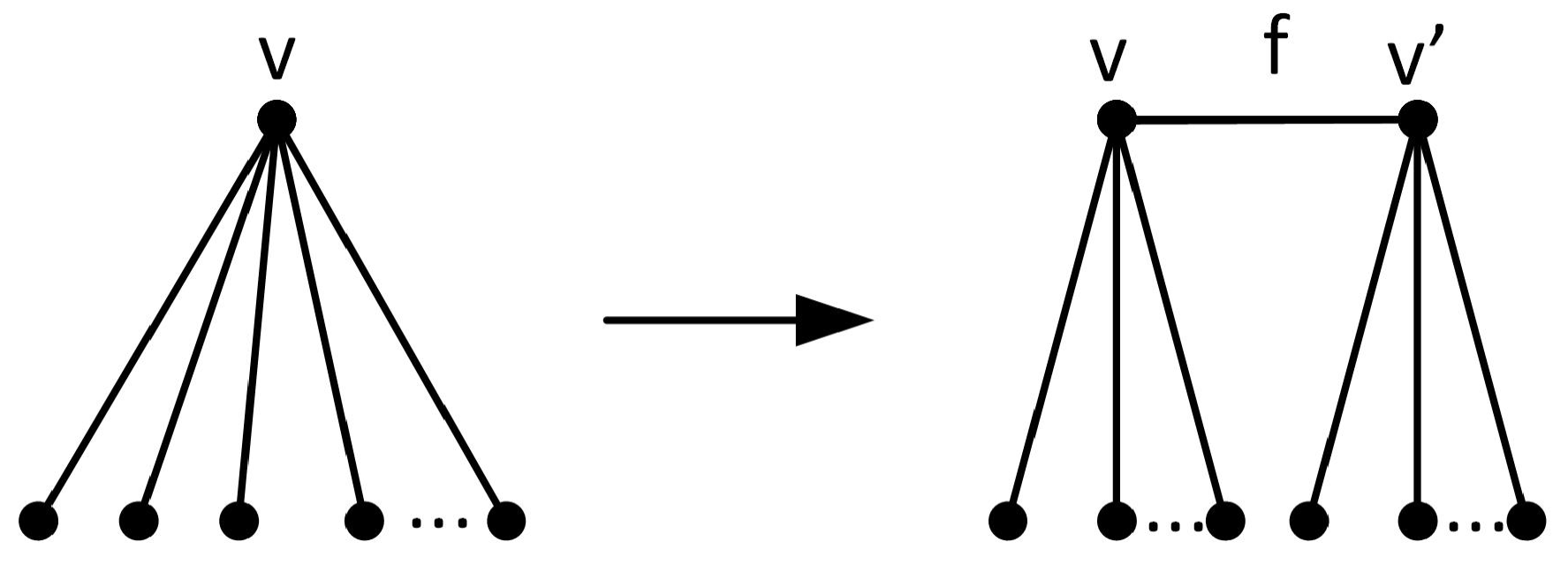
The operation that reverses edge-contraction is called a vertex split of G. To split a vertex v with , first divide into two disjoint sets S and T, both of size at least 2. Then replace v with two distinct vertices v and , join them by a new edge , and join each neighbor of v in S to v and each neighbor in T to . The resulting graph is called a vertex split of G and is denoted by . In other words is partitioned into two sets S and T, and in K, and . Observe that and .
We can get a different graph depending on the assignment of neighbors of v in G to v and in the vertex split; hence the sets S and T in the notation. With a slight abuse of notation, we can say , as each vertex split is described with a particular assignment of neighbors of v in G to v and . When performing a vertex split, we will think of as the new vertex that gets added and as the new edge that gets added. Observe that if G is 3-connected, then edge additions and vertex splits remain 3-connected. The degree condition is not necessary for an arbitrary vertex split, but required to preserve 3-connectivity. Figure 2 shows the vertex split operation.
In 1961 Tutte proved that a simple graph is 3-connected if and only if it is a wheel or is obtained from a wheel by a finite sequence of edge additions or vertex splits. This result is known as Tutte’s Wheels Theorem [1].
Theorem 1 (Tutte, 1961).
Let G be a simple graph that is not a wheel. Then G is 3-connected if and only if G can be constructed from a wheel minor by a finite sequence of edge additions or vertex splits.
The next result we need is Dirac’s characterization of 3-connected graphs without a prism minor [6]. The graphs , , and are obtained from the complete bipartite graph (shown in Figure 1) with one, two, or three edges, respectively, joining the three vertices in one class.
Theorem 2 (Dirac, 1963).
A simple 3-connected graph G has no prism-minor if and only if G is isomorphic to , , , for , , , , or , for .
Theorem 2 implies that there are only two infinite families of minimally 3-connected graphs without a prism-minor, namely for and for . Thus, we may focus on constructing minimally 3-connected graphs with a prism minor.
Next, Halin proved that minimally 3-connected graphs are sparse in the sense that there is a linear bound on the number of edges in terms of the number of vertices [5].
Theorem 3 (Halin, 1969).
Let G be a minimally 3-connected graph on vertices. Then . Moreover, if and only if .
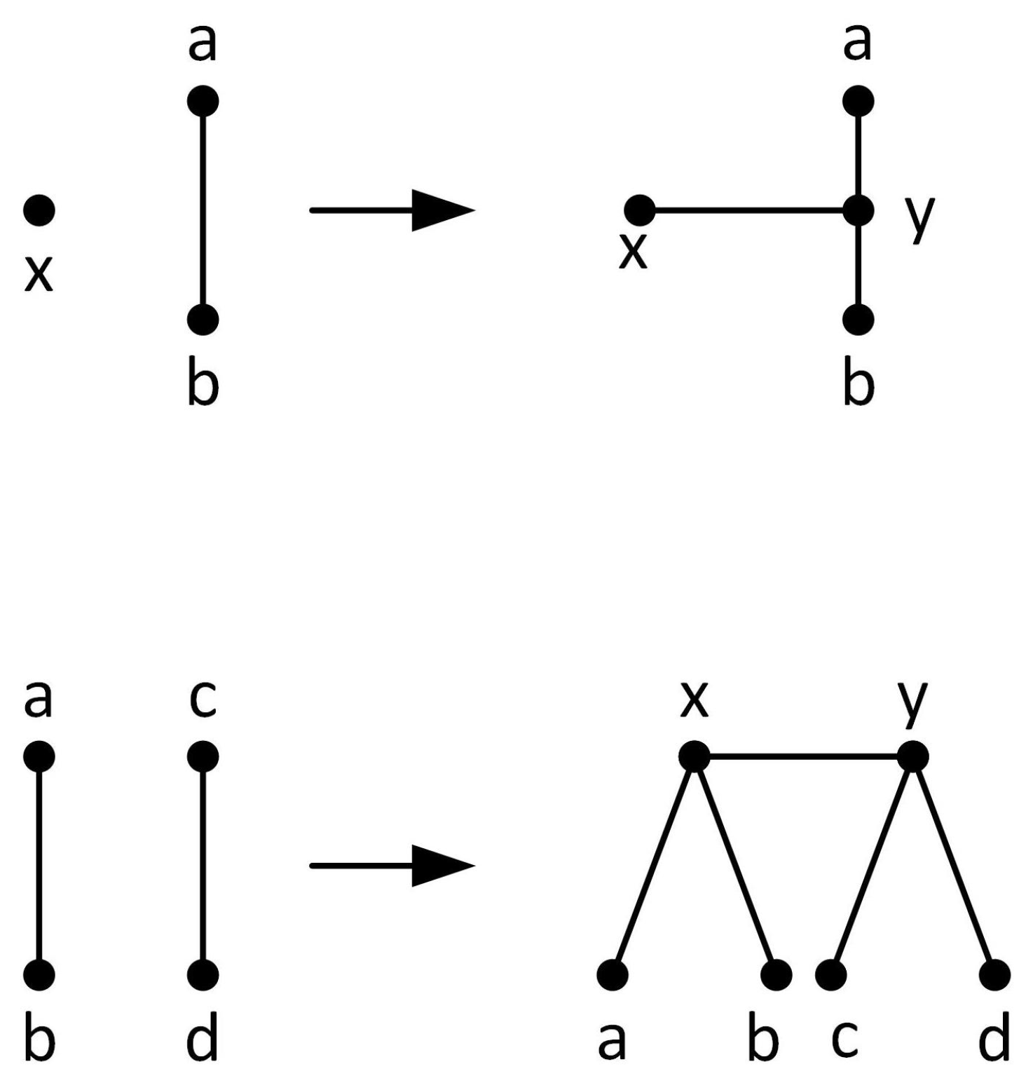
In 1969 Barnette and Grünbaum defined two operations based on subdivisions and gave an alternative construction theorem for 3-connected graphs [7]. A subdivision of G is obtained from G by replacing an edge by a path of length at least 2. Let G be a 3-connected graph. The first Barnette and Grünbaum operation is defined as follows: Subdivide an edge by vertex y and add edge for a vertex . This is what we called “bridging a vertex and an edge” in Section 1. The second Barnette and Grünbaum operation is defined as follows: Subdivide two distinct edges and , by vertices x and y, respectively, and add edge . This is what we called “bridging two edges” in Section 1. Observe that these operations, illustrated in Figure 3, preserve 3-connectivity.
Theorem 4 (Barnette and Grünbaum, 1968).
Let G be a simple graph such that . Then G is 3-connected if and only if G can be constructed from by a finite sequence of edge additions, bridging a vertex and an edge, or bridging two edges.
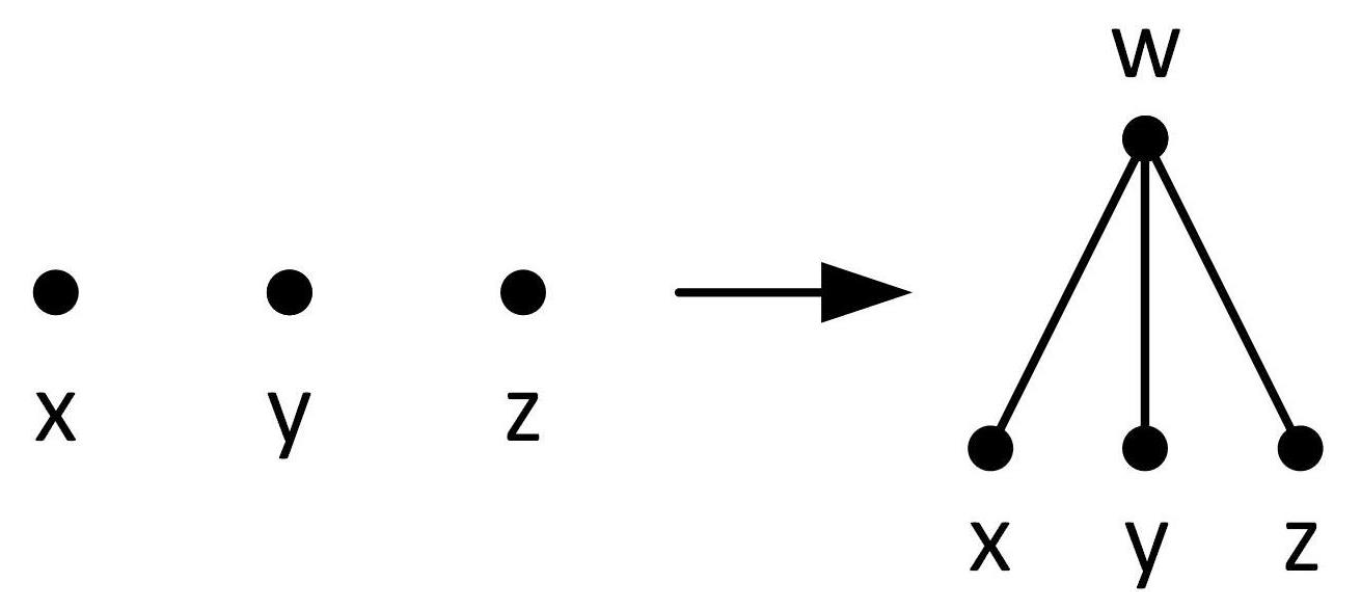
In 1986, Dawes gave a necessary and sufficient characterization for the construction of minimally 3-connected graphs starting with . He used the two Barnett and Grünbaum operations (bridging an edge and bridging a vertex and an edge) and a new operation, shown in Figure 4, that he defined as follows: select three distinct vertices in the graph and link all three to a new vertex w by adding three new edges , , and . Observe that this new operation also preserves 3-connectivity. We will call this operation “adding a degree 3 vertex” or in matroid language “adding a triad” since a triad is a set of three edges incident to a degree 3 vertex. Using these three operations, Dawes gave a necessary and sufficient condition for the construction of minimally 3-connected graphs.
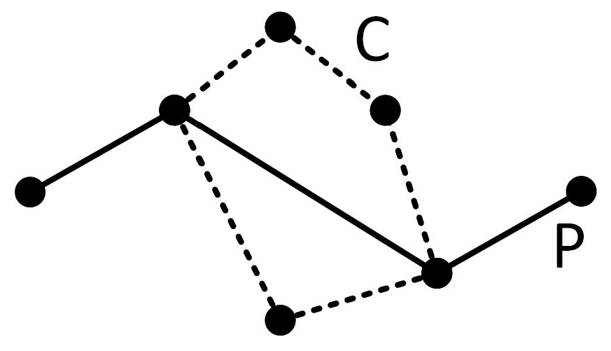
Dawes thought of the three operations, bridging edges, bridging a vertex and an edge, and the third operation as acting on, respectively, a vertex and an edge, two edges, and three vertices. Dawes showed that if one begins with a minimally 3-connected graph and applies one of these operations, the resulting graph will also be minimally 3-connected if and only if certain conditions are met. Let C be a cycle in a graph G. A chord of C is an edge that links two vertices in C. A chording path P for a cycle C is a path that has a chord e of C in it and intersects C only in the end vertices of e. In particular, none of the edges of C can be in the path. See Figure 5.
When applying the three operations listed above, Dawes defined conditions on the set of vertices and/or edges being acted upon that guarantee that the resulting graph will be minimally 3-connected. A set S of vertices and/or edges in a graph G is 3-compatible if it conforms to one of the following three types:
- , where x is a vertex of G, is an edge of G, and no -path or -path is a chording path of ;
- , where and are distinct edges of G, though possibly adjacent, and no -, -, - or -path is a chording path of ; or
- , where x, y, and z are distinct vertices of G and no -, - or -path is a chording path of G. Please note that if G is 3-connected, then x, y, and z must be pairwise non-adjacent if is 3-compatible.
For convenience in the descriptions to follow, we will use D1, D2, and D3 to refer to bridging a vertex and an edge, bridging two edges, and adding a degree 3 vertex, respectively. Dawes proved that if one of the operations D1, D2, or D3 is applied to a minimally 3-connected graph, then the result is minimally 3-connected if and only if the operation is applied to a 3-compatible set [8].
Theorem 5 (Dawes, 1986a).
Let H be a minimally 3-connected graph. Let G be constructed from H by applying D1, D2, or D3 to a set S of edges and/or vertices of H. Then G is minimally 3-connected if and only if S is a 3-compatible set in H.
Dawes also proved that, with the exception of , every minimally 3-connected graph can be obtained by applying D1, D2, or D3 to a 3-compatible set in a smaller minimally 3-connected graph.
Theorem 6 (Dawes, 1986b).
Let G be a simple graph such that . Then G is minimally 3-connected if and only if there exists a minimally 3-connected graph , such that G can be constructed by applying one of D1, D2, or D3 to a 3-compatible set in .
The next result is the Strong Splitter Theorem [9]. The rank of a graph, denoted by , is the size of a spanning tree. If G has n vertices, then .
Theorem 7.
Suppose G and H are simple 3-connected graphs such that G has a proper H-minor, G is not a wheel, and . Let . Then there is a sequence of 3-connected graphs such that , , and is a minor of such that:
- (i)
- For , and ; and
- (ii)
- For , and .
Moreover, when , for , is a triad of .
Our goal is to generate all minimally 3-connected graphs with n vertices and m edges, for various values of n and m by repeatedly applying operations D1, D2, and D3 to input graphs after checking the input sets for 3-compatibility. The process needs to be correct, in that it only generates minimally 3-connected graphs, exhaustive, in that it generates all minimally 3-connected graphs, and isomorph-free, in that no two graphs generated by the algorithm should be isomorphic to each other.
By Theorem 5, in order for our method to be correct it needs to verify that a set of edges and/or vertices is 3-compatible before applying operation D1, D2, or D3. In Section 3, we present two of the three new theorems in this paper. The first new result expresses operations D1, D2, and D3 in terms of edge additions and vertex splits. The second new result gives an algorithm for the efficient propagation of the list of cycles of a graph from a smaller graph when performing edge additions and vertex splits. We call it the “Cycle Propagation Algorithm.” Together, these two results establish correctness of the method. In Section 4 we provide details of the implementation of the Cycle Propagation Algorithm.
In Section 5 we present the algorithm for generating minimally 3-connected graphs using an “infinite bookshelf” approach to the removal of isomorphic duplicates by lists. Specifically, we show how we can efficiently remove isomorphic graphs from the list of generated graphs by restructuring the operations into atomic steps and computing only graphs with fixed edge and vertex counts in batches.
In Section 6 we show that the “Infinite Bookshelf Algorithm” described in Section 5 is exhaustive by showing that all minimally 3-connected graphs with the exception of two infinite families, and , can be obtained from the prism graph by applying operations D1, D2, and D3. This is the third new theorem in the paper.
3. Results Establishing Correctness of the Algorithm
In this section, we present two results that establish that our algorithm is correct; that is, that it produces only minimally 3-connected graphs.
According to Theorem 5, when operation D1, D2, or D3 is applied to a set S of edges and/or vertices in a minimally 3-connected graph, the result is minimally 3-connected if and only if S is 3-compatible. To check whether a set is 3-compatible, we need to be able to check whether chording paths exist between pairs of vertices. To check for chording paths, we need to know the cycles of the graph. Since enumerating the cycles of a graph is an NP-complete problem, we would like to avoid it by determining the list of cycles of a graph generated using D1, D2, or D3 from the cycles of the graph it was generated from.
To determine the cycles of a graph produced by D1, D2, or D3, we need to break the operations down into smaller “atomic” operations. The first theorem in this section, Theorem 8, expresses operations D1, D2, and D3 in terms of edge additions and vertex splits. The second theorem in this section, Theorem 9, provides bounds on the complexity of a procedure to identify the cycles of a graph generated through operations D1, D2, and D3 from the cycles of the original graph. The second theorem relies on two key lemmas which show how cycles can be propagated through edge additions and vertex splits. We refer to these lemmas multiple times in the rest of the paper.
Theorem 8.
Let G be a simple 3-connected graph. Operations D1, D2, and D3 can be expressed as a sequence of edge additions and vertex splits. Specifically:
- (a)
- D1 applied to a vertex x and an edge in G to create a new edge can be expressed as , where and ;
- (b)
- D2 applied to two edges and in G to create a new edge can be expressed as , where , and ; and
- (c)
- D3 applied to vertices x, y and z in G to create a new vertex w and edges , and can be expressed as , where , and .
Proof.
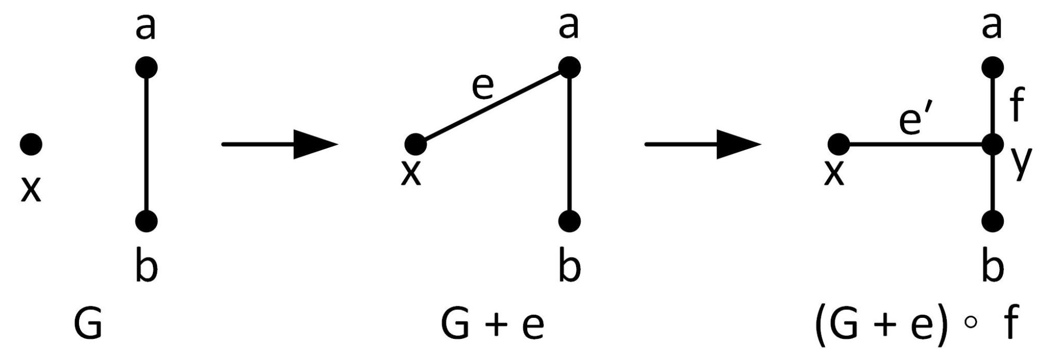
Operation D1 requires a vertex x and a nonincident edge . The operation is performed by subdividing edge by vertex y, and adding edge . We may also interpret this operation as adding an edge , and then splitting vertex a in such a way that y is the new vertex adjacent to x and b, and the new edge , as shown in Figure 6. In the process, edge is replaced with a new edge and edge is replaced with a new edge . Following this interpretation, the resulting graph is .
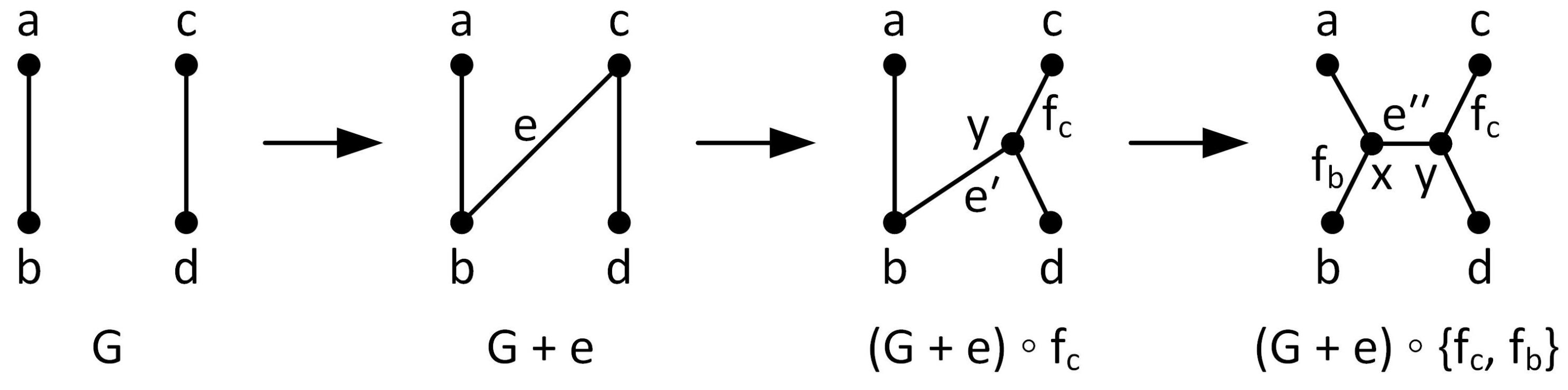
Operation D2 requires two distinct edges and , and is performed by subdividing both edges and adding a new edge connecting the two vertices. We may interpret this operation using the following steps, illustrated in Figure 7:
- (i)
- Add an edge ;
- (ii)
- split the vertex c in such a way that y is the new vertex adjacent to b and d, and the new edge ; and
- (iii)
- split the vertex b in such a way that x is the new vertex adjacent to a and y, and the new edge .
In step (ii), edge is replaced with a new edge and edge is replaced with a new edge . In step (iii), edge is replaced with a new edge and is replaced with a new edge . Following this interpretation, the resulting graph is .
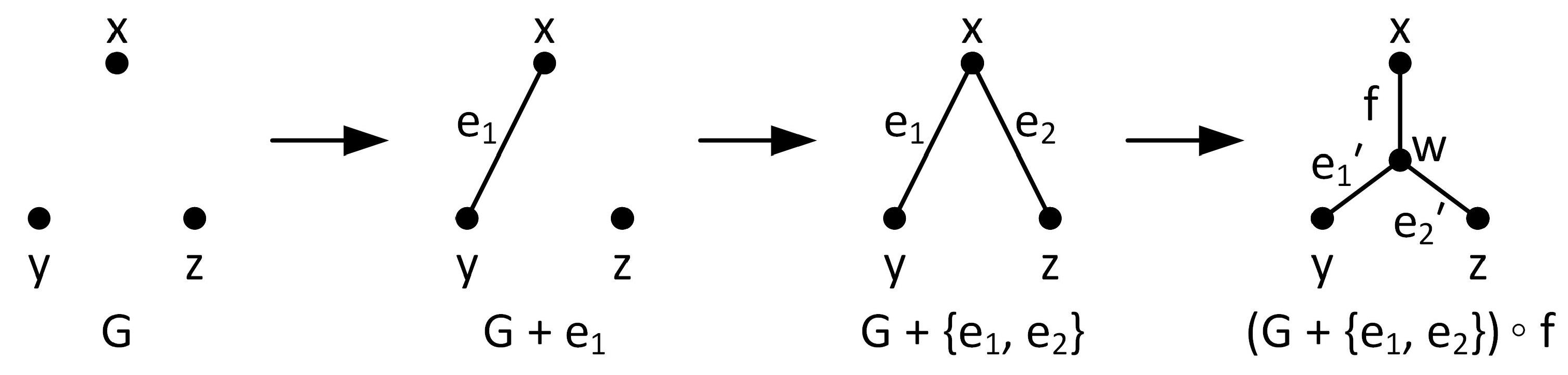
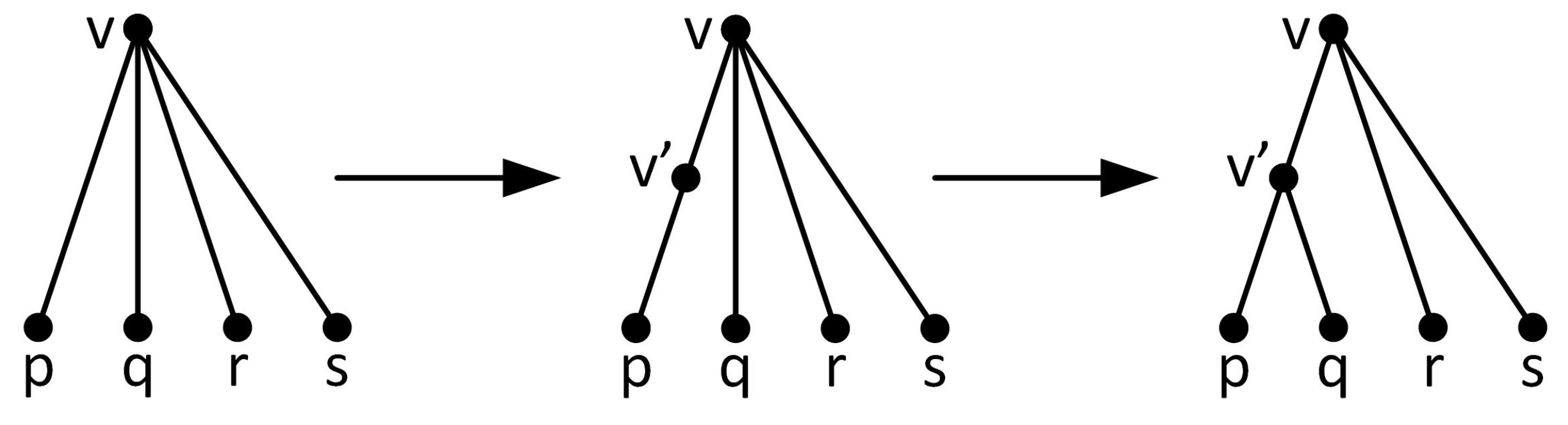
Operation D3 requires three vertices x, y, and z. The operation is performed by adding a new vertex w and edges , , and . We may interpret this operation as adding one edge , adding a second edge , and then splitting the vertex x in such a way that w is the new vertex adjacent to y and z, and the new edge . This is illustrated in Figure 8. Following this interpretation, the resulting graph is . □
In Theorem 8, it is possible that the initially added edge in each of the sequences above is a parallel edge; however we will see in Section 6 that we can avoid adding parallel edges by selecting our initial “seed” graph carefully.
Consider the function HasChordingPath, where G is a graph, a and b are vertices in G and K is a set of edges, whose value is True if there is a chording path from a to b in , and False otherwise. To efficiently determine whether S is 3-compatible, whether S is a set consisting of a vertex and an edge, two edges, or three vertices, we need to be able to evaluate HasChordingPath. To evaluate this function, we need to check all paths from a to b for chording edges, which in turn requires knowing the cycles of . The second theorem in this section establishes a bound on the complexity of obtaining cycles of a graph from cycles of a smaller graph. The proof consists of two lemmas, interesting in their own right, and a short argument.
Using Theorem 8, we can propagate the list of cycles of a graph through operations D1, D2, and D3 if it is possible to determine the cycles of a graph obtained from a graph G by:
- Adding an edge betweeen two non-adjacent vertices u and v; and
- Splitting a vertex v in G to form a new vertex of degree 3 that is incident to the new edge and two other edges.
The first lemma shows how the set of cycles can be propagated when an edge is added betweeen two non-adjacent vertices u and v.
Lemma 1 (Cycle Chording Lemma).
Let G be a simple 2-connected graph with n vertices and let be the set of cycles of G. Let be obtained from G by adding an edge between two non-adjacent vertices in G. Then the cycles of consists of:
- (i)
- ; and
- (ii)
The complexity of determining the cycles of from the cycles of G is .
Proof.
We need only show that any cycle in can be produced by (i) or (ii). Suppose C is a cycle in . If C does not contain the edge then C must also be a cycle in G. Otherwise, the edges in C other than form a path in G. Since G is 2-connected, there is another edge-disjoint path in G. Paths and together form a cycle in G, and C can be obtained from this cycle using the operation in (ii) above. Finally, the complexity of determining the cycles of from the cycles of G is because each cycle has to be traversed once and the maximum number of vertices in a cycle is n. □
The graph G in the statement of Lemma 1 must be 2-connected. It is easy to find a counterexample when G is not 2-connected; adding an edge to a graph containing a bridge may produce many cycles that are not obtainable from cycles in G by Lemma 1 (ii).
Obtaining the cycles when a vertex v is split to form a new vertex of degree 3 that is incident to the new edge and two other edges is more complicated. For the purpose of identifying cycles, we regard a vertex split, where the new vertex has degree 3, as a sequence of two “atomic” operations. Let v be a vertex in a graph G of degree at least 4, and let p, q, r, and s be four other vertices in G adjacent to v. The following two steps describe a vertex split of v in which p and q become adjacent to the new vertex and r and s remain adjacent to v:
- Subdivide the edge joining v and p, adding a new vertex .
- Remove the edge and replace it with a new edge .
This is illustrated in Figure 10. By thinking of the vertex split this way, if we start with the set of cycles of G, we can determine the set of cycles of , where is obtained by splitting vertex v to form a new vertex of degree 3 that is incident to the new edge and two other edges. The cycles of the graph resulting from step (1) above are simply the cycles of G, with any occurrence of the edge replaced with the two edges and . Cycles without the edge remain unchanged.
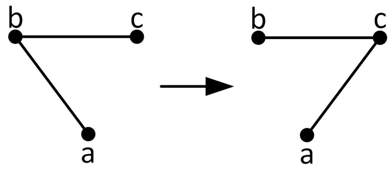
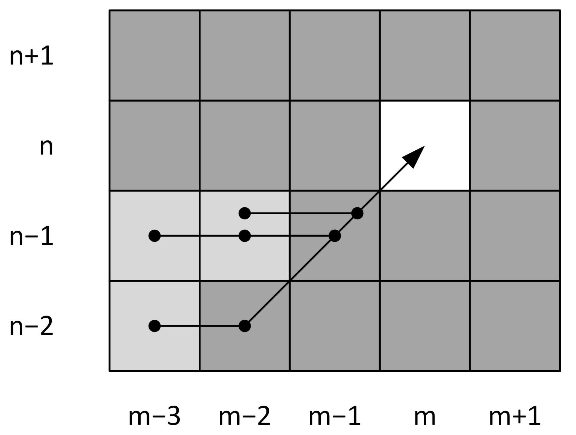
The cycles of the graph resulting from step (2) above are more complicated. Suppose G is a graph and consider three vertices a, b, and c in G where and are edges, but is not an edge. Let be the graph formed from G by deleting edge and adding edge . Think of this as “flipping” the edge to the edge as shown in Figure 11. Please note that in Figure 10, this corresponds to removing the edge and replacing it with edge .
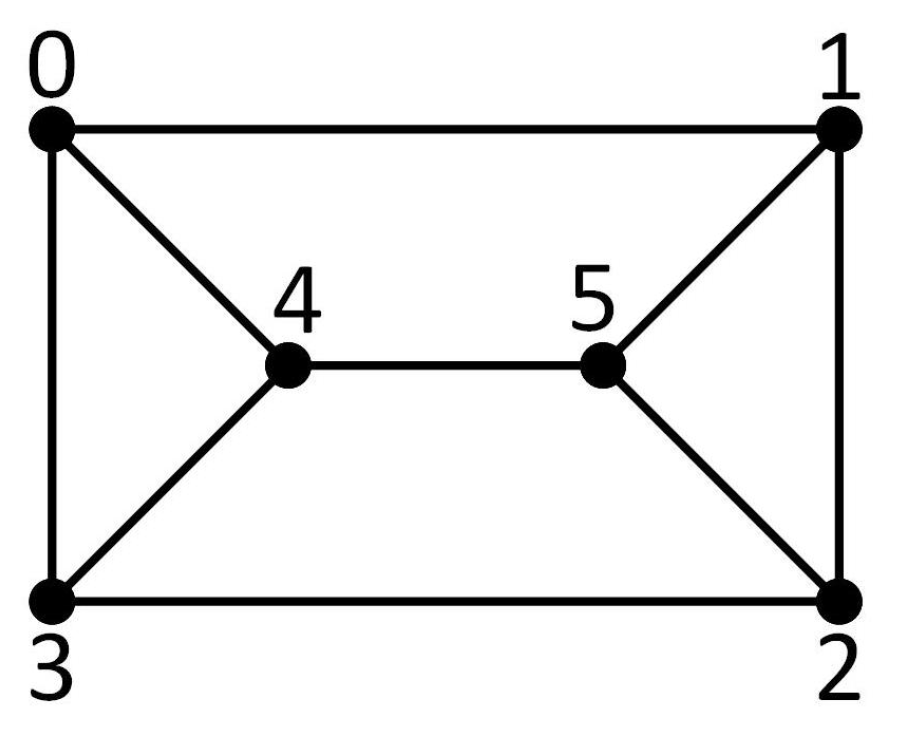
Let C be any cycle in G represented by its vertices in order. We may identify cases for determining how individual cycles are changed when is replaced with , by representing a cycle with a “pattern” that describes where a, b, and c occur in it, if at all. Consider, for example, the cycles of the prism graph with vertices labeled as shown in Figure 12:
We identify cycles of the modified graph by following the three steps below, illustrated by the example of the cycle 015430 taken from the prism graph. Eliminate the redundant final vertex 0 in the list to obtain 01543. In this example, let , , and . If none of appear in C, then there is nothing to do since it remains a cycle in .
- Rotate the list so that a appears first, if it occurs in the cycle, or b if it appears, or c if it appears: .
- Replace the vertex numbers associated with a, b and c with “a”, “b” and “c”, respectively: .
- Replace the first sequence of one or more vertices not equal to a, b or c with a diamond (⋄), the second if it occurs with a triangle (▵) and the third, if it occurs, with a square (□): .
It helps to think of these steps as symbolic operations:
15430
There is no square in the above example. If we start with cycle 012543 with , , we get
125430
This procedure will produce different results depending on the orientation used when enumerating the vertices in the cycle; we include all possible patterns in the case-checking in the next result for clarity’s sake. Moreover, as explained above, in this representation, ⋄, ▵, and □ simply represent sequences of vertices in the cycle other than a, b, or c; the sequences they represent could be of any length. Finally, unlike Lemma 1, there are no connectivity conditions on Lemma 2.
Lemma 2
(Edge Flip Lemma). Let G be a simple graph with n vertices and let be the set of cycles of G. Let such that , but . Let be the graph obtained from G by replacing with a new edge . The complexity of determining the cycles of is .
Proof.
The cycles of can be determined from the cycles of G by analysis of patterns as described above. First observe that any cycle in G that does not include at least two of the vertices a, b, and c remains a cycle in . If a cycle of G does contain at least two of a, b, and c, then we can evaluate how the cycle is affected by the flip from to based on the cycle’s pattern.
We can enumerate all possible patterns by first listing all possible orderings of at least two of a, b and c: , , , and , and then for each one identifying the possible patterns. Representing cycles in this fashion allows us to distill all of the cycles passing through at least 2 of a, b and c in G into 6 cases with a total of 16 subcases for determining how they relate to cycles in .
Case 1:: A pattern containing a and b may or may not include vertices between a and b, and may or may not include vertices between b and a. This results in four combinations: , , , and . Of these is impossible because G has no parallel edges, and therefore a cycle in G must have three edges. Cycles matching the other three patterns are propagated as follows:
| : If there is a cycle of the form in G as shown in the left-hand side of the diagram, then when the flip is implemented and is replaced with in , must be a cycle. In other words has a cycle in place of cycle . (Cycles in the diagram are indicated with dashed lines.) |  |
| : If there is a cycle of the form in G, then has a cycle , which is with replaced with . |  |
| : This cycle remains a cycle in . |  |
Case 2:: The possible patterns containing a and c are , , , and . In this case, 3 of the 4 patterns are impossible: is impossible because G has no parallel edges; and are impossible because a and c are not adjacent. Cycles matching the remaining pattern are propagated as follows:
| : has the same cycle as G. Two new cycles emerge also, namely and , because chords the cycle. |  |
Case 3:: The possible patterns containing b and c are , , , and . In this case, is impossible because G has no parallel edges. Cycles matching the other three patterns are propagated with no change:
| : This remains a cycle in . |  |
| : This remains a cycle in . |  |
| : This remains a cycle in . |  |
Case 4:: The eight possible patterns containing a, b, and c in order are , , , , , , , and . In this case, four patterns, , , , and are all impossible because a and c are not adjacent in G. Cycles matching the other four patterns are propagated as follows:
| : If G has a cycle of the form , then has a cycle , which is with replaced with . |  |
| : This remains a cycle in . |  |
| : If G has a cycle of the form , then it will be replaced in with two cycles: and . |  |
| : This remains a cycle in . |  |
Case 5:: The eight possible patterns containing a, c, and b in order are , , , , , , , and . In this case, four patterns, , , , and are impossible because a and c are not adjacent in G. Cycles matching the other four patterns are propagated as follows:
| : If G has a cycle of the form , then will have a cycle of the form , which is the original cycle with replaced with . |  |
| : If G has a cycle of the form , then will have cycles of the form and in its place. |  |
| : This remains a cycle in . |  |
| : This remains a cycle in . |  |
Case 6: There is one additional case in which two cycles in G result in one cycle in after the flip operation:
| Two cycles in G which share the common vertex b, share no other common vertices and for which the edge lies in one cycle and the edge lies in the other; that is a pair of cycles with patterns and , correspond to one cycle in of the form . |  |
In all but the last case, an existing cycle has to be traversed to produce a new cycle making it an operation because a cycle may contain at most n vertices. Without the last case, because each cycle has to be traversed the complexity would be . The last case requires consideration of every pair of cycles which is . □
Now, using Lemmas 1 and 2 we can establish bounds on the complexity of identifying the cycles of a graph obtained by one of operations D1, D2, and D3, in terms of the cycles of the original graph.
Theorem 9.
Let be a simple graph obtained from a smaller 3-connected graph G by one of operations D1, D2, and D3. Let n be the number of vertices in G and let c be the number of cycles of G. Then the cycles of can be obtained from the cycles of G by a method with complexity .
Proof.
Using Theorem 8, operation D1 can be expressed as an edge addition, followed by an edge subdivision, followed by an edge flip. By Lemmas 1 and 2, the complexities for these individual steps are , , and , respectively, so the overall complexity is . Similarly, operation D2 can be expressed as an edge addition, followed by two edge subdivisions and edge flips, and operation D3 can be expressed as two edge additions followed by an edge subdivision and an edge flip, so the overall complexity of propagating the list of cycles for D2 and D3 is also . □
4. Cycle Propagation Algorithm
To check when operations D1, D2, and D3 can be performed, we must check for chording paths between specific vertices. Let G be a graph with n vertices and let denote its set of cycles. Since we will be considering only one input graph at a time, in this section is unambiguous. Given the set of cycles of the input graph G, Lemmas 1 and 2 allow us to define three procedures ApplyFlipEdge, ApplyAddEdge, and ApplySubdivideEdge, which compute the set of cycles of a graph modified by flipping an edge, adding an edge, or subdividing an edge. This allows us to propagate the set of cycles for the new graphs we produce in terms of the cycles of G, which in turn allows us to avoid the NP-complete problem of computing all the cycles of a graph.
The procedures described in this section rely on two simpler procedures, ChordCycle and Chords, which are defined informally below.
- ChordCycle(): This is the procedure described in Lemma 1. Given a cycle C and a pair of vertices and which both occur in the cycle, but are not adjacent, return a pair of cycles generated as follows: The first cycle is created by starting at , then proceeding to , and then following the existing cycle from back to . The second cycle begins with and proceeds along the existing cycle until is reached, and then returns to . That is, if the existing cycle consists of verticesthen the two new cycles will consist of verticesandIts complexity is .
- Chords(): This procedure simply determines whether an edge chords a cycle. Given a cycle C and two vertices and , determine whether there is an edge that chords C. Its complexity is .
Next, we present the three procedures ApplyFlipEdge, ApplyAddEdge and ApplySubdivideEdge, respectively.
- ApplyFlipEdge(): This procedure is also described informally, as its steps closely follow the cases in the proof of Lemma 2. Given the set of cycles of a graph G and vertices a, b, and c with edges and , but no edge , ApplyFlipEdge generates the list of cycles of the graph produced by replacing edge with a new edge , using the procedure outlined with Lemma 2. Its complexity is .
- ApplyAddEdge(): This procedure computes the resulting cycles when adding an edge to a graph, where is the set of cycles and a and b are two non-adjacent vertices. It creates the new set of cycles by adding the cycles from the old graph and the new cycles created by ChordCycle for any cycle that is chorded by . Its complexity is . Pseudocode is shown in Algorithm 1.
Algorithm 1 Compute cycles for an edge addition 1. procedure ApplyAddEdge() 2. 3. for do 4. 5. if then 6. 7. 8. end if 9. end for 10. end procedure - ApplySubdivideEdge(): This procedure computes cycles resulting when subdividing an edge, where is the set of cycles of the graph, a and b are two adjacent vertices, and vertex c is being added to subdivide the edge . Its complexity is . Pseudocode is shown in Algorithm 2.
Algorithm 2 Compute cycles for subdividing an edge 1: procedure ApplySubdivideEdge(, a, b, c) 2: 3: for do 4: if C contains edge then 5: Add cycle C with replaced with to S 6: else 7: Add C to S 8: end if 9: end for 10: end procedure
5. Isomorph-Free Graph Construction
This section is further broken into three subsections.
5.1. Organizing Graph Construction to Minimize Isomorphism Checking
When we apply operation D1 to a graph, we end up with a graph that has two more edges and one more vertex. When we apply operation D2 to a graph, we end up with a graph that has three more edges and two more vertices. When we apply operation D3 to a graph, we end up with a graph that has three more edges and one more vertex. This creates a problem if we want to avoid generating isomorphic graphs, because we have to keep track of graphs of different sizes at the same time. To prevent this, we want to focus on doing everything we need to do with graphs with one particular number of edges and vertices all at once. In particular, if we consider operations D1, D2, and D3 as algorithms, then:
- D1 takes a graph G with n vertices and m edges, a vertex and an edge as input, and produces a graph with vertices and edges (see Theorem 8 (i));
- D2 takes a graph G with n vertices and m edges, and two edges as input, and produces a graph with vertices and edges (see Theorem 8 (ii)); and
- D3 takes a graph G with n vertices and m edges, and three vertices as input, and produces a graph with vertices and edges (see Theorem 8 (iii)).
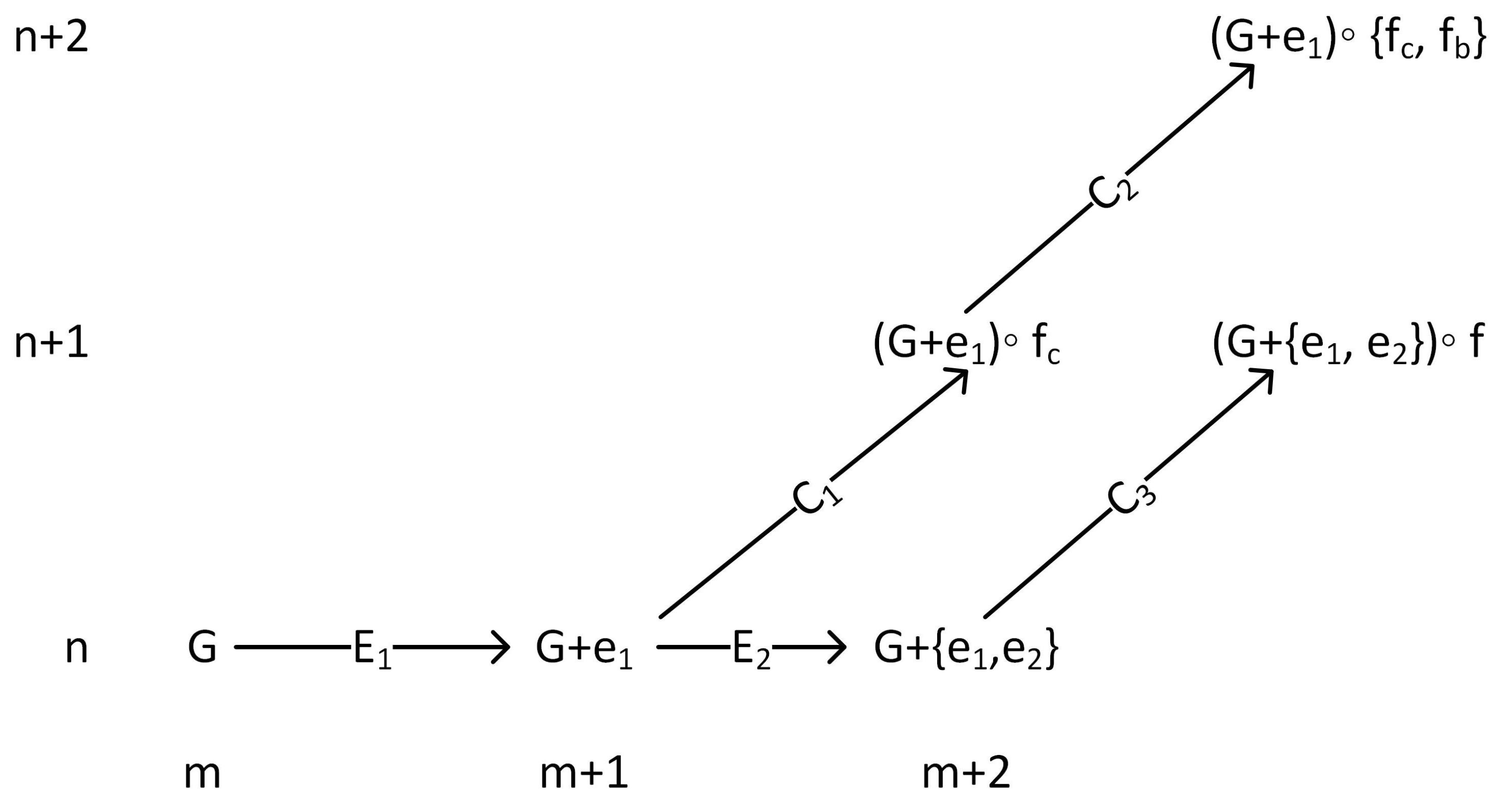
Figure 13 outlines the process of applying operations D1, D2, and D3 to an individual graph. The specific procedures E1, E2, C1, C2, and C3 will be detailed in Section 5.3.
To avoid generating graphs that are isomorphic to each other, we wish to maintain a list of generated graphs and check newly generated graphs against the list to eliminate those for which isomorphic duplicates have already been generated. We immediately encounter two problems with this approach: checking whether a pair of graphs is isomorphic is a computationally expensive operation; and the number of graphs to check grows very quickly as the size of the graphs, both in terms of vertices and edges, increases.
The first problem can be mitigated by using McKay’s nauty system [10] (available for download at http://pallini.di.uniroma1.it/) to generate certificates for each graph. The nauty certificate function produces a data artifact from a graph in such a way that if and only if . Thus we can reduce the problem of checking isomorphism to the problem of generating certificates, and then compare a newly generated graph’s certificate to the set of certificates of graphs already generated.
The second problem can be mitigated by a change in perspective. While Figure 13 demonstrates how a single graph will be treated by our process, consider Figure 14, which we refer to as the “infinite bookshelf”. As the entire process of generating minimally 3-connected graphs using operations D1, D2, and D3 proceeds, with each operation divided into individual steps as described in Theorem 8, the set of all generated graphs with n vertices and m edges will contain both “finished”, minimally 3-connected graphs, and “intermediate” graphs generated as part of the process. What does this set of graphs look like?
- For operation D1, the set may include graphs of the form , where G has n vertices and edges, and graphs of the form , where G has vertices and edges.
- For operation D2, the set may include graphs of the form , where G has n vertices and edges, graphs of the form , where G has vertices and edges, and graphs of the form , where G has vertices and edges.
- For operation D3, the set may include graphs of the form where G has n vertices and edges, graphs of the form , where G has n vertices and edges, and graphs of the form , where G has vertices and edges.
When generating graphs, by storing some data along with each graph indicating the steps used to generate it, and by organizing graphs into subsets, we can generate all of the graphs needed for the algorithm with n vertices and m edges in one batch. Organized in this way, we only need to maintain a list of certificates for the graphs generated for one “shelf”, and this list can be discarded as soon as processing for that shelf is complete. We do not need to keep track of certificates for more than one shelf at a time.
Section 5.2 breaks down the graphs in one shelf formally by their place in operations D1, D2, and D3. Section 5.3 then describes how the procedures for each shelf work and interoperate.
5.2. The Algorithm Is Isomorph-Free
To make the process of eliminating isomorphic graphs by generating and checking nauty certificates more efficient, we organize the operations in such a way as to be able to work with all graphs with a fixed vertex count n and edge count m in one batch. Specifically, for an combination, we define sets , where * represents 0, 1, 2, or 3, and as follows:
- only ever contains of the “root” graph; i.e., the prism graph. So for values of m and n other than 9 and 6, . All graphs in , , , and are minimally 3-connected.
- consists of graphs generated by adding an edge to a minimally 3-connected graph with vertices and n edges.
- consists of graphs generated by adding an edge to a graph in that is incident with the edge added to form the input graph.
- consists of graphs generated by splitting a vertex in a graph in that is incident to the edge added to form the input graph, after checking for 3-compatibility.
- consists of graphs generated by splitting a vertex in a graph in that is incident to the same edge as the vertex split to form the input graph, after checking for 3-compatibility.
- consists of graphs generated by splitting a vertex in a graph in that is incident to the two edges added to form the input graph, after checking for 3-compatibility.
Then, beginning with and , we construct graphs in , , , and , in that order, from input graphs with vertices and n edges, and with vertices and edges. As graphs are generated in each step, their certificates are also generated and stored. Any new graph with a certificate matching another graph already generated, regardless of the step, is discarded, so that the full set of generated graphs is pairwise non-isomorphic. At the end of processing for one value of n and m the list of certificates is discarded.
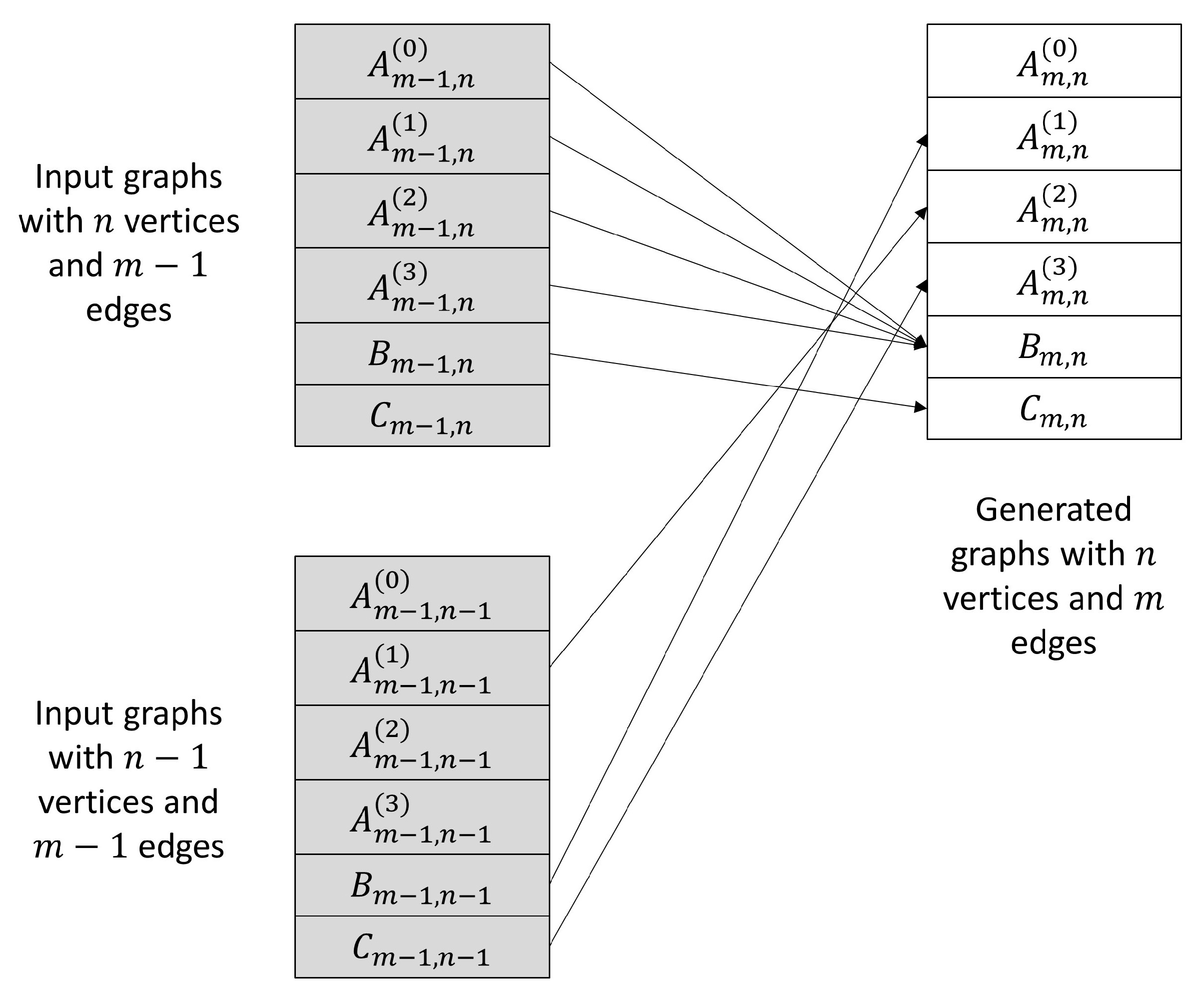
For any value of n, we can start with and proceed until no more graphs or generated or, when , when . By Theorem 3, no further minimally 3-connected graphs will be found after when ; however we still need to generate single- and double-edge additions to be used when considering graphs with vertices. Proceeding in this fashion, at any time we only need to maintain a list of certificates for the graphs for one value of m and n. The generation sources and targets are summarized in Figure 15, which shows how the graphs with n vertices and m edges, in the upper right-hand box, are generated from graphs with n vertices and edges in the upper left-hand box, and graphs with vertices and edges in the lower left-hand box.
5.3. Infinite Bookshelf Algorithm
This subsection contains a detailed description of the algorithms used to generate graphs, implementing the process described in Section 5.2.
The process of computing , , and is broken down into individual procedures E1, E2, C1, C2, and C3, each of which operates on an input graph with one less edge, or one less edge and one less vertex, than the graphs it produces. The procedures are implemented using the following component steps, as illustrated in Figure 13:
- Procedure E1 is applied to graphs in , which are minimally 3-connected, to generate all possible single edge additions given an input graph G. This is the first step for operations D1, D2, and D3, as expressed in Theorem 8. The cycles of the output graphs are constructed from the cycles of the input graph G (which are carried forward from earlier computations) using ApplyAddEdge. The results, after checking certificates, are added to .
- Procedure E2 is applied to graphs in and treats an input graph as in operation D3, as expressed in Theorem 8. It adds all possible edges with a vertex in common to the edge added by E1 to yield a graph . This is the second step in operation D3 as expressed in Theorem 8. Cycles in these graphs are also constructed using ApplyAddEdge. The results, after checking certificates, are added to .
- Procedure C1 is applied to graphs in and treats an input graph as as defined in operations D1 and D2, as expressed in Theorem 8. It generates two splits for each input graph, one for each of the vertices incident to the edge added by E1. This is the second step in operations D1 and D2, and it is the final step in D1. It uses ApplySubdivideEdge and ApplyFlipEdge to propagate cycles through the vertex split. The results, after checking certificates, are added to . This procedure only produces splits for graphs for which the original set of vertices and edges is 3-compatible, and as a result it yields only minimally 3-connected graphs.
- Procedure C2 is applied to graphs in and treats an input graph as as defined in operation D2, as expressed in Theorem 8. It generates splits of the remaining un-split vertex incident to the edge added by E1. This is the third step of operation D2 when the new vertex is incident with e; otherwise it comprises another application of D1. It uses ApplySubdivideEdge and ApplyFlipEdge to propagate cycles through the vertex split. The results, after checking certificates, are added to . This procedure only produces splits for 3-compatible input sets, and as a result it yields only minimally 3-connected graphs.
- Procedure C3 is applied to graphs in and treats an input graph as as defined in operation D3 as expressed in Theorem 8. For each input graph, it generates one vertex split of the vertex common to the edges added by E1 and E2. It uses ApplySubdivideEdge and ApplyFlipEdge to propagate cycles through the vertex split. The results, after checking certificates, are added to . This procedure only produces splits for 3-compatible input sets, and as a result it yields only minimally 3-connected graphs.
While C1, C2, and C3 produce only minimally 3-connected graphs, they may produce different graphs that are isomorphic to one another. We use Brendan McKay’s nauty to generate a canonical label for each graph produced, so that only pairwise non-isomorphic sets of minimally 3-connected graphs are ultimately output.
The following procedures are defined informally:
- AddEdge()—Given a graph G and a pair of vertices u and v in G, this procedure returns a graph formed from G by adding an edge connecting u and v. When it is used in the procedures in this section, we also use ApplyAddEdge immediately afterwards, which computes the cycles of the graph with the added edge. The complexity of AddEdge is because the set of edges of G must be copied to form the set of edges of .
- SplitVertex()—Given a graph G, a vertex v and two edges and , this procedure returns a graph formed from G by adding a vertex , adding an edge connecting v and , and replacing the edges and with edges and . When it is used in the procedures in this section, we also use ApplySubdivideEdge and ApplyFlipEdge, which compute the cycles of the graph with the split vertex. The complexity of SplitVertex is , again because a copy of the graph must be produced.
- NoChordingPaths()—Given the set of cycles of a graph G, a set P of pairs of vertices and another set X of edges, this procedure determines whether there are any chording paths connecting pairs of vertices in P in . Its complexity is , as it requires all simple paths between two vertices to be enumerated, which is . This function relies on HasChordingPath as defined in Section 3.
The rest of this subsection contains a detailed description and pseudocode for procedures E1, E2, C1, C2 and C3. The worst-case complexity for any individual procedure in this process is the complexity of C2: .
Procedure E1 is responsible for implementing the first step of operations D1, D2, and D3. It generates all single-edge additions of an input graph G, using ApplyAddEdge to propagate the list of cycles. Its complexity is , as it requires each pair of vertices of G to be checked, and for each non-adjacent pair ApplyAddEdge is used to propagate cycles. Pseudocode is shown in Algorithm 3.
| Algorithm 3 First edge addition procedure |
| 1: procedure E1 (G, ) |
| 2: |
| 3: for do |
| 4: for do |
| 5: if then |
| 6: AddEdge |
| 7: ApplyAddEdge |
| 8: |
| 9: end if |
| 10: end for |
| 11: end for |
| 12: return S |
| 13: end procedure |
Procedure E2 is responsible for implementing the second step of operation D3. It also generates single-edge additions of an input graph, but under a certain condition. Specifically, given an input graph with cycles , as produced by E1, E2 produces all graphs , where the new edge is adjacent to . Its complexity is , as ApplyAddEdge is used every time a new graph is generated, and each vertex is checked for eligibility. Pseudocode is shown in Algorithm 4.
| Algorithm 4 Second edge addition procedure |
| 1: procedure E2(G, u, v, ) |
| 2: |
| 3: for do |
| 4: if then |
| 5: AddEdge |
| 6: ApplyAddEdge |
| 7: |
| 8: end if |
| 9: if then |
| 10: AddEdge |
| 11: ApplyAddEdge |
| 12: |
| 13: end if |
| 14: end for |
| 15: return S |
| 16: end procedure |
Procedure C1 is responsible for implementing the second step of operations D1 and D2. These steps are illustrated in Figure 6 and Figure 7, respectively, though a bit of bookkeeping is required to see how C1 corresponds to those operations. C1 starts with a graph generated by E1; let denote the added edge. Observe that the chording path checks are made in H, which is .
First, for any vertex in G, where there are no chording or paths in , we split b to add a new vertex x adjacent to a, b, and c. This is the same as the second step illustrated in Figure 6 with c, b, a, and x in C1 corresponding to x, a, b, and y in the figure, respectively. It is also the same as the second step illustrated in Figure 7, with c, b, a, and x in C1 corresponding to b, c, d, and y in the figure, respectively.
Second, we must consider splits of the other end vertex of the newly added edge e, namely c. For any vertex in G where there are no chording or paths in , we split c to add a new vertex y adjacent to b, c, and d. This is the same as the second step illustrated in Figure 6 with b, c, d, and y in C1 corresponding to x, a, b, and y in the figure, respectively. It is also the same as the second step illustrated in Figure 7, with b, c, d, and y in C1 corresponding to b, c, d, and y in the figure, respectively.
Since C1 must make calls to ApplyFlipEdge, where , its complexity is . Pseudocode is shown in Algorithm 5.
| Algorithm 5 First vertex split procedure |
| 1: procedureC1(G, b, c, ) |
| 2: |
| 3: for do ▹ Split b |
| 4: if NoChordingPaths then |
| 5: SplitVertex |
| 6: ApplySubdivideEdge |
| 7: ApplyFlipEdge |
| 8: |
| 9: end if |
| 10: end for |
| 11: for do ▹ Split c |
| 12: if NoChordingPaths then |
| 13: SplitVertex |
| 14: ApplySubdivideEdge |
| 15: ApplyFlipEdge |
| 16: |
| 17: end if |
| 18: end for |
| 19: return S |
| 20: end procedure |
Procedure C2 is responsible for implementing the third step in operation D2, as illustrated in Figure 7. It starts with a graph generated by C1; we denote and f shown in the figure as and , respectively. d represents the third vertex that becomes adjacent to the new vertex in C1, so d and y are also adjacent.
First, for any vertex a adjacent to b other than c, d, or y, for which there are no , , , or chording paths in , we split b to add a new vertex x adjacent to b, a and y. This is the same as the third step illustrated in Figure 7.
Second, for any pair of vertices a and k adjacent to b other than c, d, or y, and for which there are no or chording paths in , we split b to add a new vertex x adjacent to b, a and k (leaving y adjacent to b, unlike in the first step).
Since C2 must make calls to ApplyFlipEdge, where , its complexity is . Pseudocode is shown in Algorithm 6.
| Algorithm 6 Second vertex split procedure |
| 1: procedure C2() |
| 2: |
| 3: for do ▹ Final step of Operation (c) |
| 4: if NoChordingPaths then |
| 5: SplitVertex |
| 6: ApplySubdivideEdge |
| 7: ApplyFlipEdge |
| 8: |
| 9: end if |
| 10: end for |
| 11: for do ▹ Final step of Operation (d) |
| 12: if NoChordingPaths then |
| 13: SplitVertex |
| 14: ApplySubdivideEdge |
| 15: ApplyFlipEdge |
| 16: |
| 17: end if |
| 18: end for |
| 19: return S |
| 20: end procedure |
Procedure C3 is responsible for implementing the third step in operation D3, as illustrated in Figure 8. It starts with a graph generated by E2, where and are two incident edges. A single new graph is generated in which x is split to add a new vertex w adjacent to x, y and z, if there are no , , or chording paths in . Because C3 makes one call to ApplyFlipEdge, its complexity is . Pseudocode is shown in Algorithm 7.
| Algorithm 7 Third vertex split procedure |
|
6. The Algorithm Is Exhaustive
Theorem 5 and Theorem 6 (Dawes’ results) state that, if G is a minimally 3-connected graph and is obtained from G by applying one of the operations D1, D2, and D3 to a set S of vertices and edges, then is minimally 3-connected if and only if S is 3-compatible, and also that any minimally 3-connected graph other than can be obtained from a smaller minimally 3-connected graph by applying D1, D2, or D3 to a 3-compatible set. This shows that application of these operations to 3-compatible sets of edges and vertices in minimally 3-connected graphs, starting with , will exhaustively generate all such graphs. However, as indicated in Theorem 9, in order to maintain the list of cycles of each generated graph, we must express these operations in terms of edge additions and vertex splits.
Consider the graph itself, as shown in Figure 16. Observe that is a 3-compatible set because there are clearly no chording - or -paths in , so we may apply D1 to produce another minimally 3-connected graph, which is actually as shown in the figure. However, since there are already edges and in the graph, if we are to apply our step-by-step procedure to accomplish the same thing, we will be required to add a parallel edge. We would like to avoid this, and we can accomplish that by beginning with the prism graph instead of . We are now ready to prove the third main result in this paper.
Theorem 10.
Let G be a simple minimally 3-connected graph. Then one of the following statements is true:
- 1.
- for and G can be obtained from by applying operation D1 to the spoke vertex x and a rim edge ;
- 2.
- for and G can be obtained from by applying operation D3 to the 3 vertices in the smaller class; or
- 3.
- G has a prism minor, for , and G can be obtained from a smaller minimally 3-connected graph with a prism minor, where , using operation D1, D2, or D3.
Proof.
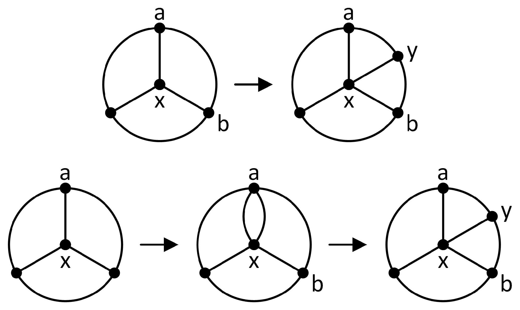
Theorem 2 characterizes the 3-connected graphs without a prism minor. Of these, the only minimally 3-connected ones are for and for . Observe that for , , where e is a spoke and f is a rim edge, such that are incident to a degree 3 vertex. Therefore can be obtained from by applying operation D1 to the spoke vertex x and a rim edge . The set is 3-compatible because any chording edge of a cycle in would have to be a spoke edge, and since all rim edges have degree three the chording edge cannot be extended into a - or -path.
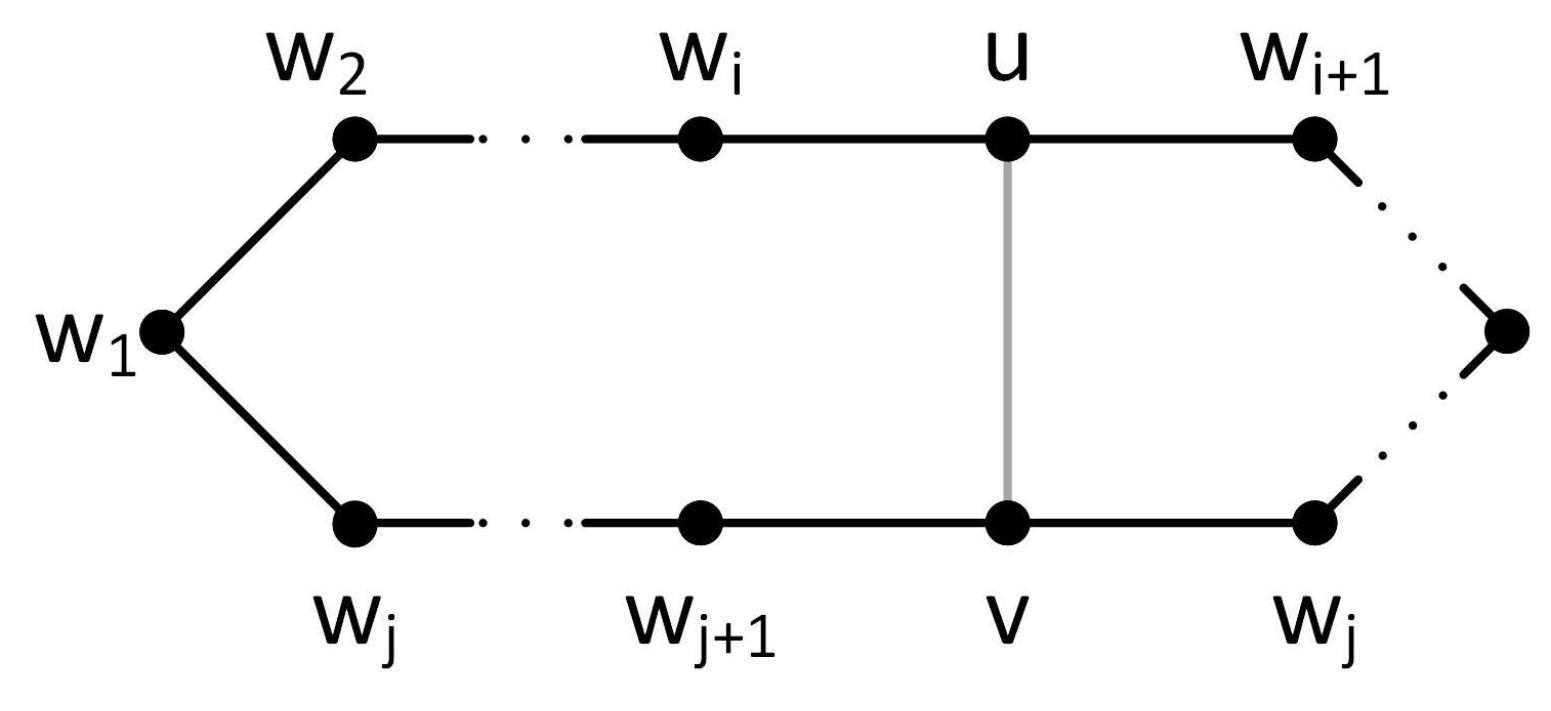
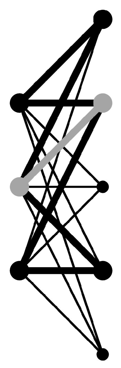
Observe that, for , , where w is a degree 3 vertex. Therefore, can be obtained from a smaller minimally 3-connected graph of the same family by applying operation D3 to the three vertices in the smaller class. The set of three vertices is 3-compatible because the degree of each vertex in the larger class is exactly 3, so that any chording edge cannot be extended into a chording path connecting vertices in the smaller class, as illustrated in Figure 17.
If G has a prism minor, by Theorem 7, with the prism graph as H, G can be obtained from a 3-connected graph with vertices and edges via an edge addition and a vertex split, from a graph with vertices and edges via two edge additions and a vertex split, or from a graph with vertices and edges via an edge addition and two vertex splits; that is, by operation D1, D2, or D3, respectively, as expressed in Theorem 8. By Theorem 6, all minimally 3-connected graphs can be obtained from smaller minimally 3-connected graphs by applying these operations to 3-compatible sets. □
We constructed all non-isomorphic minimally 3-connected graphs up to 12 vertices using a Python implementation of these procedures. The total number of minimally 3-connected graphs for 4 through 12 vertices is published in the Online Encyclopedia of Integer Sequences. Table 1 below lists these values. These numbers helped confirm the accuracy of our method and procedures.
The number of non-isomorphic 3-connected cubic graphs of size n, where n is even, is published in the Online Encyclopedia of Integer Sequences as sequence A204198. This sequence only goes up to . We were able to obtain the set of 3-connected cubic graphs up to 20 vertices as shown in Table 2.
All of the minimally 3-connected graphs generated were validated using a separate routine based on the Python iGraph (https://igraph.org/python/) vertex_disjoint_paths method, in order to verify that each graph was 3-connected and that all single edge-deletions of the graph were not. The overall number of generated graphs was checked against the published sequence on OEIS.
The 3-connected cubic graphs were verified to be 3-connected using a similar procedure, and overall numbers for up to 14 vertices were checked against the published sequence on OEIS.
The minimally 3-connected graphs were generated in 31 h on a PC with an Intel Core I5-4460 CPU at 3.2 GHz and 16 Gb of RAM. The 3-connected cubic graphs were generated on the same machine in five hours.
The algorithm’s running speed could probably be reduced by running parallel instances, either on a larger machine or in a distributed computing environment. MapReduce, or a similar programming model, would need to be used to aggregate generated graph certificates and remove duplicates. It is also possible that a technique similar to the canonical construction paths described by Brinkmann, Goedgebeur and McKay [11] could be used to reduce the number of redundant graphs generated.
Even with the implementation of techniques to propagate cycles, the slowest part of the algorithm is the procedure that checks for chording paths. It may be possible to improve the worst-case performance of the cycle propagation and chording path checking algorithms through appropriate indexing of cycles.
The code, instructions, and output files for our implementation are available at https://github.com/rkingan/m3c. The output files have been converted from the format used by the program, which also stores each graph’s history and list of cycles, to the standard graph6 format, so that they can be used by other researchers.
The authors would like to thank the referees and editor for their valuable comments which helped to improve the manuscript.
Author Contributions
All authors contributed equally to this work. All authors have read and agreed to the published version of the manuscript.
Funding
This research received no external funding.
Institutional Review Board Statement
Not applicable.
Informed Consent Statement
Not applicable.
Data Availability Statement
All data and source code related to this research is available for download at https://github.com/rkingan/m3c.
Conflicts of Interest
The authors declare no conflict of interest.
References
- Tutte, W.T. A theory of 3-connected graphs. Indag. Math. 1961, 23, 441–455. [Google Scholar] [CrossRef] [Green Version]
- Tutte, W.T. Connectivity in Graphs; Toronto University Press: Toronto, ON, Canada, 1967. [Google Scholar]
- Hopcroft, J.E.; Tarjan, R.E. Dividing a graph into triconnected components. SIAM J. Comput. 1973, 2, 135–158. [Google Scholar] [CrossRef]
- Schmidt, J.M. Structure and Constructions of 3-Connected Graphs. Ph.D. Thesis, Free University of Berlin, Berlin, Germany, 2011. [Google Scholar]
- Halin, R. Untersuchungen uber minimale n-fach zusammenhangende graphen. Math. Ann. 1969, 182, 175–188. [Google Scholar] [CrossRef]
- Dirac, G.A. Some results concerning the structure of graphs. Can. Math. Bull. 1963, 6, 183–210. [Google Scholar] [CrossRef]
- Barnette, D.W.; Grünbaum, B. On Steinitz’s theorem concerning convex 3-polytopes and on some properties of planar graphs. In The Many Facets of Graph Theory. Lecture Notes in Mathematics; Chartrand, G., Kapoor, S.F., Eds.; Springer: Berlin/Heidelberg, Germany, 1969; Volume 110, pp. 27–40. [Google Scholar]
- Dawes, R.W. Minimally 3-connected graphs. J. Comb. Theory Ser. B 1986, 40, 159–168. [Google Scholar] [CrossRef] [Green Version]
- Kingan, S.R.; Lemos, M. Strong Splitter Theorem. Ann. Comb. 2014, 18-1, 111–116. [Google Scholar] [CrossRef] [Green Version]
- McKay, B.D. Practical Graph Isomorphism. Congr. Numer. 1981, 30, 45–87. [Google Scholar] [CrossRef]
- Brinkmann, G.; Goedgebeur, J.; McKay, B.D. Generation of cubic graphs. Discret. Math. Theor. Comput. Sci. 2011, 13, 69–80. [Google Scholar]
Figure 1.
The prism graph, for , and for .

Figure 2.
Tutte’s vertex split operation.

Figure 3.
Bridging two edges and bridging a vertex and an edge.

Figure 4.
Dawes’ third operation.

Figure 5.
A chording path.

Figure 6.
Operation D1 interpreted as an edge addition followed by a vertex split.

Figure 7.
Operation D2 interpreted as an edge addition followed by two vertex splits.

Figure 8.
Operation D3 interpreted as two edge additions followed by a vertex split.

Figure 9.
Chording a cycle

Figure 10.
Rethinking a vertex split.

Figure 11.
Flipping an edge.

Figure 12.
The prism graph.

Figure 13.
Minimally 3-connected graph construction.

Figure 14.
Infinite bookshelf approach to minimizing isomorphism checking.

Figure 15.
Graph generation steps.

Figure 16.
Operation D1 applied to .

Figure 17.
with a cycle highlighted in black and a chording edge highlighted in gray.


Table 1.
3-connected graphs and minimally 3-connected graphs graphs from oeis.org.
Table 1.
3-connected graphs and minimally 3-connected graphs graphs from oeis.org.
| n | Minimally 3-Connected Graphs (A199676) |
|---|---|
| 6 | 3 |
| 7 | 5 |
| 8 | 18 |
| 9 | 57 |
| 10 | 285 |
| 11 | 1513 |
| 12 | 9824 |
Table 2.
3-connected cubic graphs.
| n | 3-Connected Cubic Graphs |
|---|---|
| 8 | 4 |
| 10 | 14 |
| 12 | 57 |
| 14 | 341 |
| 16 | 2828 |
| 18 | 30,468 |
| 20 | 396,150 |
Publisher’s Note: MDPI stays neutral with regard to jurisdictional claims in published maps and institutional affiliations. |
© 2021 by the authors. Licensee MDPI, Basel, Switzerland. This article is an open access article distributed under the terms and conditions of the Creative Commons Attribution (CC BY) license (http://creativecommons.org/licenses/by/4.0/).
Share and Cite
MDPI and ACS Style
Costalonga, J.P.; Kingan, R.J.; Kingan, S.R. Constructing Minimally 3-Connected Graphs. Algorithms 2021, 14, 9. https://0-doi-org.brum.beds.ac.uk/10.3390/a14010009
AMA Style
Costalonga JP, Kingan RJ, Kingan SR. Constructing Minimally 3-Connected Graphs. Algorithms. 2021; 14(1):9. https://0-doi-org.brum.beds.ac.uk/10.3390/a14010009
Chicago/Turabian StyleCostalonga, João Paulo, Robert J. Kingan, and Sandra R. Kingan. 2021. "Constructing Minimally 3-Connected Graphs" Algorithms 14, no. 1: 9. https://0-doi-org.brum.beds.ac.uk/10.3390/a14010009
Note that from the first issue of 2016, this journal uses article numbers instead of page numbers. See further details here.