
Decision Tree-Based Adaptive Reconfigurable Cache Scheme


State Key Laboratory of ASIC and System, Fudan University, Shanghai 201203, China
*
Author to whom correspondence should be addressed.
Algorithms 2021, 14(6), 176; https://0-doi-org.brum.beds.ac.uk/10.3390/a14060176
Submission received: 28 April 2021
/
Revised: 25 May 2021
/
Accepted: 31 May 2021
/
Published: 1 June 2021
(This article belongs to the Special Issue Algorithms in Reconfigurable Computing)
Abstract
:Applications have different preferences for caches, sometimes even within the different running phases. Caches with fixed parameters may compromise the performance of a system. To solve this problem, we propose a real-time adaptive reconfigurable cache based on the decision tree algorithm, which can optimize the average memory access time of cache without modifying the cache coherent protocol. By monitoring the application running state, the cache associativity is periodically tuned to the optimal cache associativity, which is determined by the decision tree model. This paper implements the proposed decision tree-based adaptive reconfigurable cache in the GEM5 simulator and designs the key modules using Verilog HDL. The simulation results show that the proposed decision tree-based adaptive reconfigurable cache reduces the average memory access time compared with other adaptive algorithms.
1. Introduction
The speed of logical processors has been improved rapidly over the last 50 years following Moore’s law, while main memory access latency has been improved slowly, resulting in a growing gap between processor speed and main memory access latency [1]. The cache was introduced as a high-speed, small-capacity memory to mitigate the speed difference between the processor and the main memory. Most commercial processors implement a cache with fixed parameters. However, studies have shown that a wide variety of applications have different preferences for cache parameters; even the same application can have different preferences for caches at different running phases [2]. The cache with fixed parameters cannot match all applications, resulting in performance loss [3]. For example, applications prefer lower associativity in the jump phase. Higher associativity is preferred in the loop-operating phase, because the temporal and spatial locality of the data is better.
Multicore processors are widely used in modern computer systems to improve performance. Applications such as integrated circuit synthesis, weather forecasting, and fluid simulation are designed to be executed in parallel to take advantage of the multicore processors [4]. They usually run on desktop computing platforms or high-performance servers that are not sensitive to energy consumption. In this application scenario, the system performance can be further improved by dynamically tuning the cache associativity according to the requirements of applications runtime. The implementation of an adaptive reconfigurable cache requires two major elements: First, an adaptive decision-making algorithm is required to determine the current optimal cache associativity based on the monitored information of the system and to control the cache to tune to the optimal associativity; second, a cache memory that can change associativity in real-time is required. Static reconfiguration requires running the application with different cache associativity in advance to find the optimal associativity and then running the application with the best associativity. It is impractical to find the optimal associativity for all applications. The behavior of the application is too complex to build a model that reflects the relationship between cache associativity and runtime statistical information in real-time. Machine learning algorithms are suitable for solving such optimization problems.
To solve these problems, this paper proposes an adaptive reconfigurable cache scheme based on decision tree algorithm: (1) an optimal associativity search scheme is designed and used as the data set to train the optimal associativity decision tree model; (2) an adaptive decision-making algorithm based on the decision tree is used to periodically tune the associativity to reduce the average memory access time of the L2 cache; (3) the dirty block writeback and cache flush operation are introduced after associativity tuning, which avoids the modification of the cache coherent protocol. Compared with other adaptive schemes, the adaptive reconfigurable cache scheme based on the decision tree proposed in this paper significantly reduces the average memory access time.
2. Related Work
A reconfigurable cache is an optimization route for caches, and the optimization can be conducted from multiple perspectives.
Regarding the architecture of reconfigurable cache, it can be reconfigured by tuning the cache capacity, number of associative ways, and cache line size utilizing techniques such as way-shutdown, way-concatenation, and line-resizing [5,6,7,8,9,10,11,12]. Gordon-Ross et al. [5] proposed a reconfigurable cache with which the cache way can be configured to be instruction dedicated, data dedicated, and used in combinations to optimize system performance. Xie et al. [6] tuned the associativity of the L2 cache dynamically when the miss rate was beyond the system threshold. Po-Yang et al. [7] optimized multi-thread application performance in a multi-core system by tuning cache capacity and cache line size. The authors of [8] concentrated on reducing the vulnerability due to soft errors and saving energy by reconfiguring cache parameters. The authors of [9,10] adopted cache reconfiguration for performance, energy, and vulnerability tradeoffs in a multi-core system. Charles et al. [11] co-optimized the cache and NoC (network on chip) energy using a machine learning algorithm.
For cache replacement policies, DLPR [13] improves NUCA system performance by monitoring the dynamic link latency and dynamically adjusting the cache replacement policy. Lee et al. [14] realized adaptive replacement policy and cache partition utilizing a replacement policy adaptable miss curve estimation. ACR policy [15] dynamically tracks the maximum lifetime of each application in the shared last-level-cache (LLC) and adjusts the replacement policy to make full use of the limited cache capacity.
The cache partitioning technique partitions the shared LLC for each concurrent application. The reconfiguration of the cache partitioning scheme can also improve cache performance. KPart [3] clusters applications by identifying the similarity of the memory access behavior of applications and allocates cache capacity among clusters. Applications within a cluster can share this part of the cache, reducing data conflicts. The LLC-PC controller [16] utilizes the Palloc page coloring framework to partition the cache at runtime by evaluating the performance improvement of increasing the size of the cache partition. Jenga [17] defined cache hierarchies by software. It treats 3D-stacked DRAM and SRAM as a cache resource pool and generates adaptive cache hierarchies for each application.
Decision trees have low overhead and simple implementations that can be used for adaptive control algorithms. The authors of [18] utilized a decision tree to perform dynamic voltage and frequency scaling on a heterogeneous multicore system to optimize energy and performance. LESSON [19] uses the decision tree model to reduce both the static and dynamic power of NoCs by shutting down network components with low utilization. To the best of our knowledge, there are no existing studies regarding the adaptive reconfigurable cache based on the decision tree.
3. Proposed Adaptive Reconfigurable Cache Scheme Based on Decision Tree
3.1. Overview of Adaptive Reconfigurable Cache
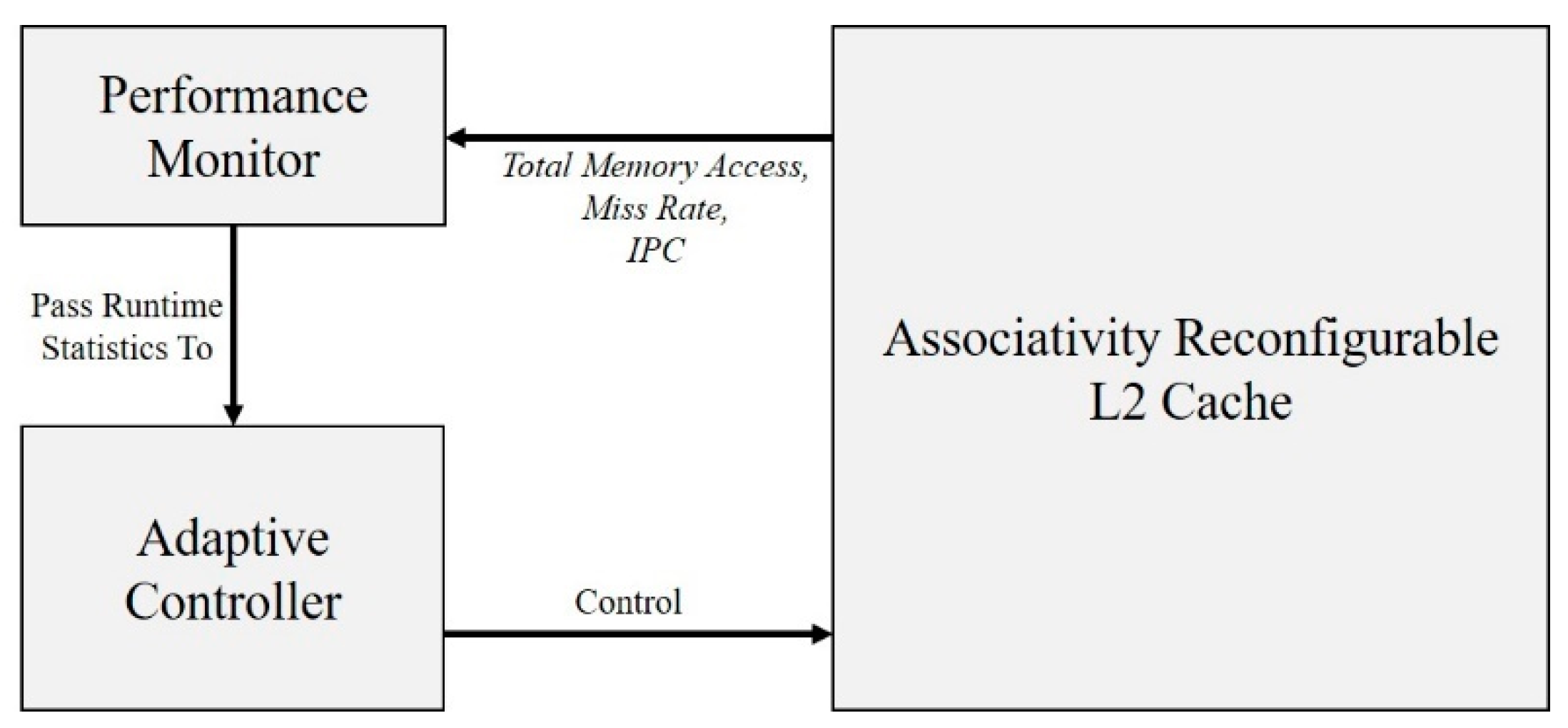
The decision tree-based adaptive reconfigurable cache scheme consists of a performance monitor, an adaptive controller, and an L2 cache with reconfigurable associativity. The performance monitor is used to collect information including the instruction-per-cycle (IPC) value in the current reconfiguration period, the total number of memory access, and the L2 cache miss rate, which is needed for the decision tree model to make decisions. Based on the above statistics, the adaptive controller decides the optimal associativity of the L2 cache through the decision tree model and controls the cache to tune the associativity. Figure 1 shows the architecture of the proposed adaptive reconfigurable cache scheme.
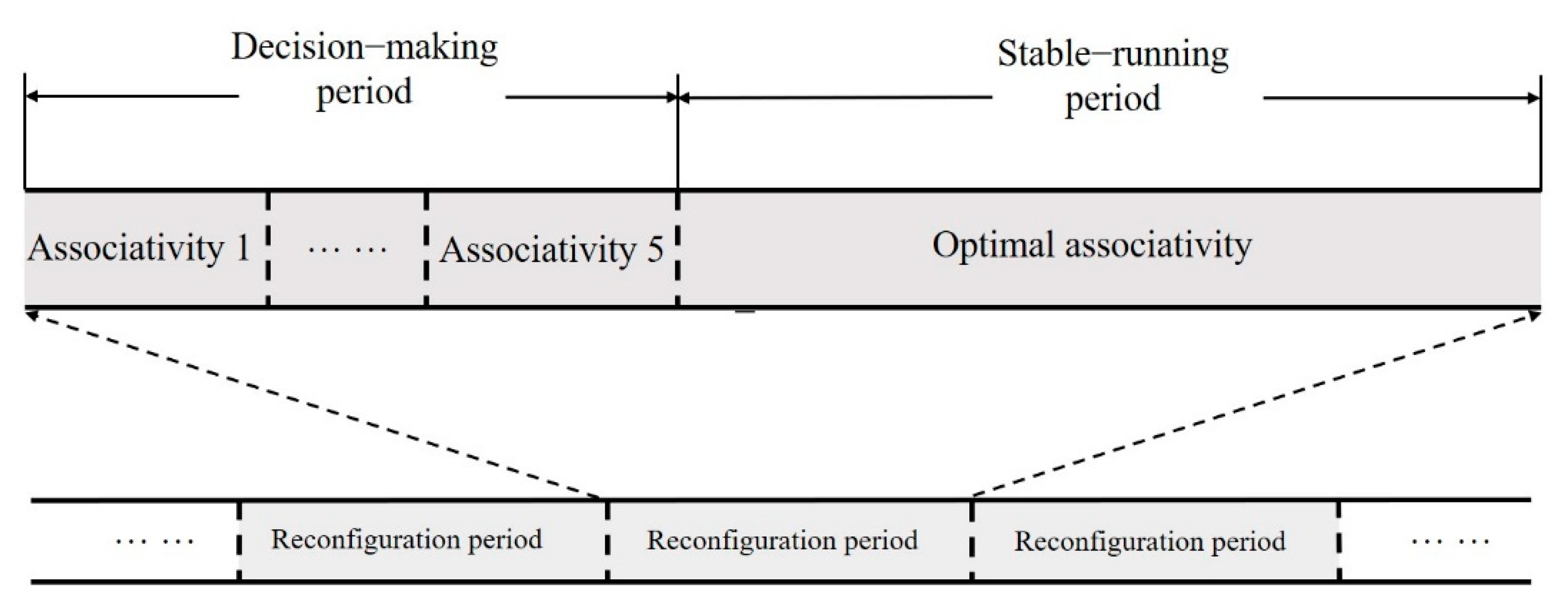
Applications have time-varying behavior of memory access at run time, but the behavior of applications can be considered stable for a short time interval. Based on this feature, the application run time is divided into reconfiguration periods of the same length, and within each reconfiguration period, the application runs with the current optimal associativity. The reconfiguration period is further divided into a decision-making period and a stable-running period. The division scheme of run time is shown in Figure 2. During the decision-making period, the information within current runtimes, such as cache miss rate, total number of memory access, and instructions per cycle (IPC) is collected by the performance monitor. Then, the adaptive controller uses the above information to determine the optimal associativity. At the end of the decision-making period, the adaptive controller tunes the associativity so that the application runs with the optimal associativity during the stable-running period.
In this study, the average access time (AMAT) is used as a metric to evaluate the system performance, and CPU clock cycle (C.C.) is used as the unit for the access time, hit time, miss penalty and other parameters covered subsequently in this paper. Equation (1) demonstrates how to calculate the average memory access time (AMAT):
where Hit Time is the latency of cache hit, Miss Rate is the percentage of the cache miss number, and Miss Penalty is the latency of cache miss.
3.2. Optimal Associativity Search Scheme
This subsection discusses how the optimal cache associativity configuration can be obtained. The decision tree model of optimal associativity in Section 3.3 can be trained by using the obtained configuration as a sample of the dataset.
The traditional method generates the optimal associativity scheme by traversing all candidate associativity for each reconfiguration period. The running time of an application is divided into N reconfiguration periods with the same length as shown in Figure 2, and 5 candidate associativities can be adopted in each reconfiguration period. In this case, there are 5N possible cache associativity combination schemes for the running of a certain application. It takes a long time to traverse all the configurations, which makes it difficult to obtain the optimal configuration.
This paper designs an optimal associativity configuration search scheme, which can generate the optimal configuration only by running the workload once. As shown in Figure 3, the decision-making period of each reconfiguration period is further divided into five equal sub-periods. The optimal associativity search scheme is as follows:
Step 1: Run applications using five candidate associativities sequentially in the corresponding five sub-periods of the decision-making period;
Step 2: Select the associativity that provides the highest performance as the optimal configuration and use this associativity during the stable-running period;
Step 3: The optimal associativity of each reconfiguration period and its corresponding IPC, total number of memory access, and L2 cache miss rate are recorded as a sample of the dataset.
The decision-making period uses the associativity of the last reconfiguration period. Therefore, the current optimal associativity is also related to the optimal associativity of the last reconfiguration period in addition to the IPC, the total number of memory accesses, and miss rate. With these elements being combined, an optimal cache configuration can be expressed as Equation (2):
The parameters to be monitored are in curly brackets. The subscript i indicates the current reconfiguration period, and the subscript i − 1 indicates the last reconfiguration period. These parameters are collected during the decision-making period. The associativity on the right side is the decision of the current optimal associativity.
The performance of the adaptive reconfigurable cache is related to the length of the reconfiguration period. The shorter the reconfiguration period, the more accurate the observed application behavior. The application behavior may change during the long reconfiguration period, while the statistical information cannot reflect this change. However, reducing the reconfiguration period will increase the reconfiguration number, resulting in a large reconfiguration overhead. System performance will be compromised when reconfiguration overhead is greater than performance gain benefit from reconfiguration. In Section 5, the optimal reconfiguration overhead is discussed.
3.3. Adaptive Decision-Making Algorithm Based on Decision Tree
The determination of the optimal cache associativity based on the statistical information of the application run time is a typical classification task. The decision tree algorithm can be used to solve classification problems. The decision tree model consists of a root, internal nodes, branches, and leaf nodes. Its exact structure is determined during the training process. The classification rules of the decision tree are easy to understand, and the hardware implementation of the model is simple because it can be implemented in an if-then-else way.
This paper uses the J48 algorithm in WEKA [20], which is an open-source machine learning framework, to train a decision tree model of the optimal associativity. The J48 algorithm is a widely used decision tree algorithm. The J48 algorithm can automatically prune the decision tree model to avoid overfitting. It can train a decision tree model with more accuracy and less manual intervention. The pseudocode of the J48 algorithm is shown in Algorithm 1 [21]. A set of training data D and an attribute list A are the input of the J48 algorithm. Starting from the root, the J48 algorithm calculates the information gain ratio of each attribute in list A and selects the attribute X with the largest information gain ratio as the classification criterion of the current node. Then, it creates branches and splits samples into subsets D1, D2, …, Dk. D1, D2, …, Dk are created as child nodes of the current decision node and split recursively on these child nodes until the samples in each partition have the same label.
| Algorithm 1 Pseudocode of the J48 algorithm [21]. |
| J48 (Training data D, Attribute A): |
| if all samples in D have the same label: |
| return a leaf node with that label |
| let X∈A be the attribute with the largest information gain ratio |
| let R be a tree root labeled with attribute X |
| let D1, D2, …, Dk be the partition produced by splitting D on attribute X |
| for each Di∈D1, D2, …, Dk: |
| let Ri = J48(Di, A − {X}) |
| add Ri as a new branch of R |
| returnR |
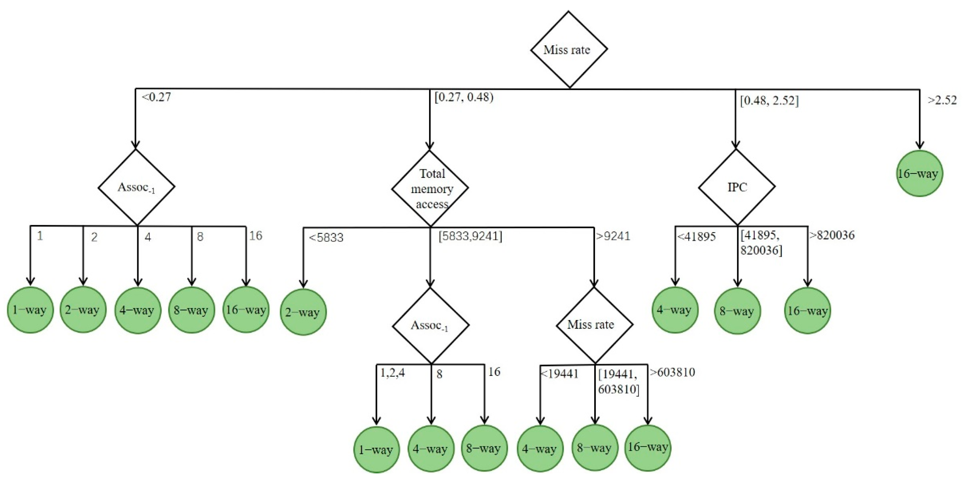
The trained decision tree model is shown in Figure 4. Each node of the tree is assigned an attribute selected by the J48 algorithm. The root is the cache miss rate in the current reconfiguration period, and the attribute value is divided into four intervals by the J48 algorithm in the training process, which are miss rate < 0.27, 0.27 ≤ miss rate < 0.48, 0.48 ≤ miss rate ≤ 2.52, and miss rate > 2.52. Starting from the root, the decision is made by taking a branch depending on the attribute miss rate and reaching the next node. The branch is continuously taken depending on the attribute corresponding to the current node, and this process is repeated until a leaf node is reached, which is the decision result.
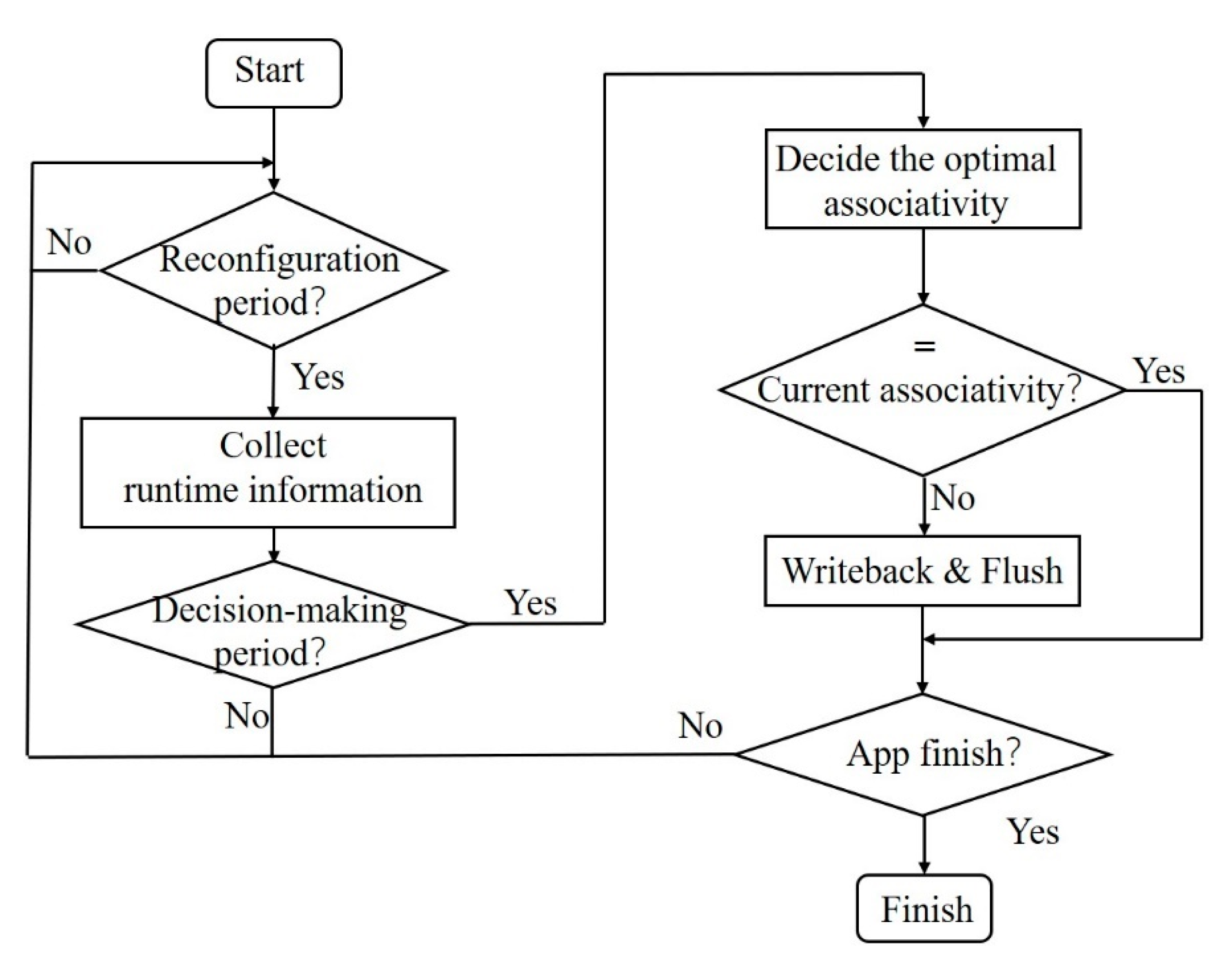
Based on the decision tree model of the optimal associativity, the adaptive control algorithm’s workflow is shown in Figure 5. The adaptive control algorithm is executed as follows:
Step 1: Determine whether the reconfiguration period has been reached according to the current number of clock cycles, and do not perform any operation before the reconfiguration period is reached;
Step 2: After reaching the reconstruction period, the performance monitor starts to collect the information of the application runtime, including the cache miss rate, the total number of memory accesses, and the instructions per cycle (IPC), which are used for the optimal associativity decision;
Step 3: Preserve the statistics of runtime information until the decision-making period is reached;
Step 4: The adaptive controller determines the optimal associativity in the current reconfigurable period according to the trained decision tree model after reaching the decision-making period;
Step 5: If the optimally determined associativity is consistent with the current associativity, the system will continue to operate with the current associativity—jump to step 7;
Step 6: The controller sends an interruption to the CPU, writes back dirty blocks, flushes the cache, and tunes the associativity to the optimal associativity when inconsistent;
Step 7: Determine whether the application has finished running. When it ends, the adaptive control algorithm runs to completion after the application is finished; otherwise, it continues to run to Step 1.
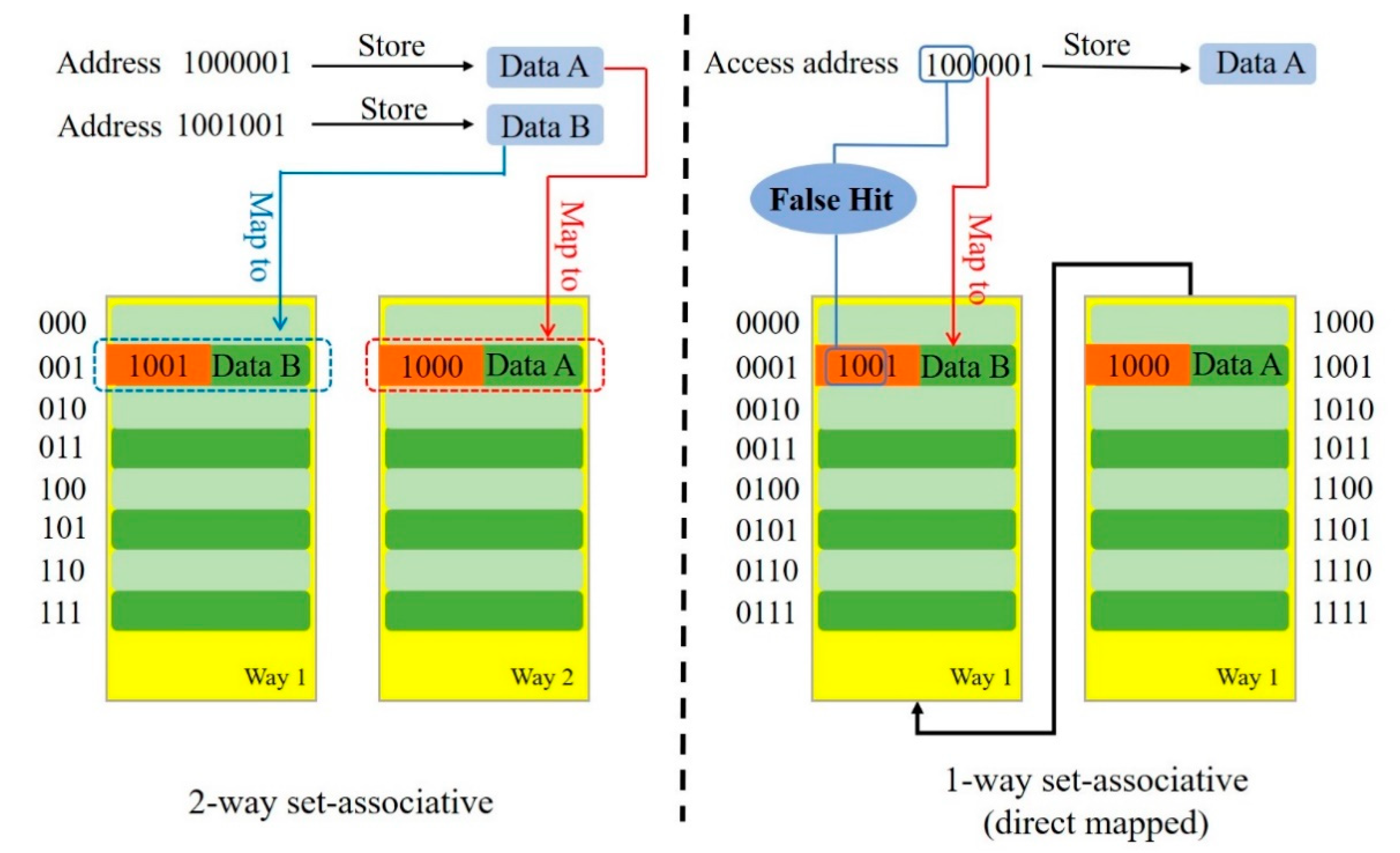
Errors may be caused when the two adjacent reconfiguration periods have different associativities because the mapping relationship between the cache and main memory is changed. Taking the false hit caused by associativity decrease as an example, the cache is two-way set-associative in the first reconfiguration period. The data stored in the main memory address 1000001 is A. Suppose A is stored in the second way of the 001 cache set. At the same time, the tag stored in the tag array is the upper four bits of the address 1000. The first cache way in the same cache set holds data B from memory address 1001001 with tag 1001 in the tag array. In the next reconfiguration period, the cache is tuned to be direct-mapped (1-way set-associative). At this moment, there is only one cache block in the cache set 0001. Same as the last reconfiguration period, the block holds data B from address 1001001, and the tag in the corresponding tag array is still 1001. If the CPU issues a memory access request to address 1000001, the cache set 0001 will be selected; the upper three bits of the tag 1001 stored in the tag array are compared with the upper three bits of the address 1000001 requested by the CPU. The comparison result is true, and the cache returns a hit signal. The CPU reads B from address 1000001, while the address 1000001 holds data A. This will cause system errors. Figure 6 shows the false hit caused by an associativity decrease.
To solve the false hit problem without modifying the complex cache coherent protocol, all dirty blocks are written back to the main memory and the cache is flushed before the reconfiguration. These operations will stall the CPU; all cache accesses after the cache flush will experience a compulsory miss, which will also compromise the system performance. Therefore, it is necessary to evaluate the impact of different reconfiguration periods on performance. This is discussed in Section 5.
3.4. Associativity Reconfigurable Cache
By changing the indexing policy, cache blocks that originally belonged to two different ways are concatenated to tune the associativity from four to two. Figure 7 illustrates the associativity reconfigurable cache with fixed cache size.
Cache sets are indexed using the index field in the address. When cache size is constant, higher associativity will bring fewer cache sets and fewer bits required to index the cache sets. The width of the address is fixed, so bits of the tag array increase. The address decoding unit is designed to process indexes with different bits. For an 8 MB cache with 64 bytes cache block size, the number of sets reaches the maximum value when the cache is direct-mapped (1-way set-associative) and a 17-bit index is required. Therefore, the row decoding unit can process up to a 17-bit address.
At the same time, the tag comparator is designed to compare inputs with different widths. To ensure that there are enough tag bits under all associativity, the tag array should be designed according to the associativity with the maximum value of tag width. The maximum value of the tag width is 13 bits when it is a 16-way set-associative cache. With the valid bit and the dirty bit, the total width of the tag array is 15 bits.
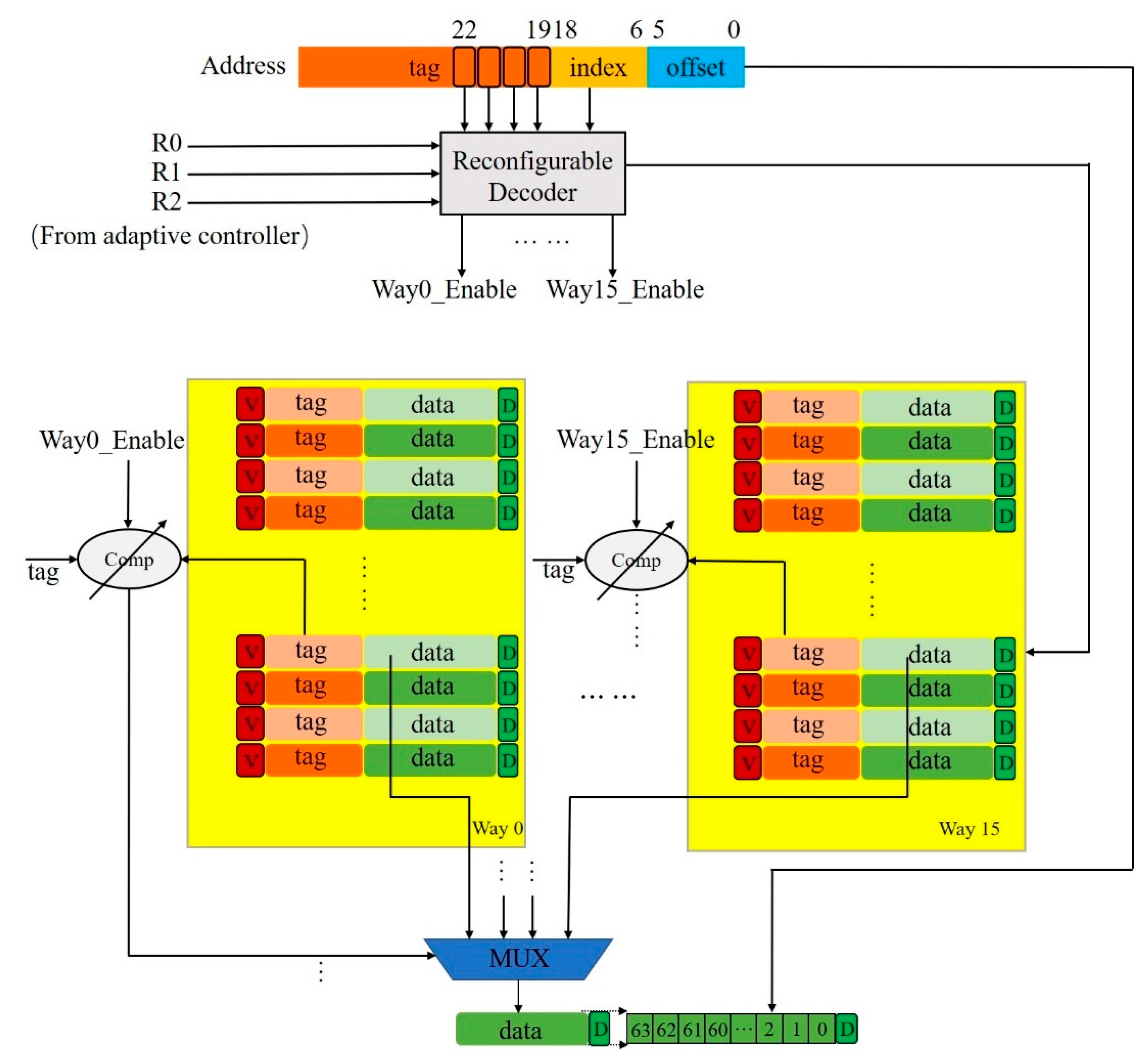
Figure 8 illustrates the hardware architecture of associativity-reconfigurable cache. The basic structure of the cache is designed according to the maximum associativity. The cache array is divided into 16 equal-capacity ways, each of which has a comparator to determine whether a cache hit has occurred. The adaptive controller controls the row decoder and comparator to tune the cache associativity based on the decision of the trained decision tree model. Taking a 16-way set-associative cache as an example, the row decoder processes a 13-bit index, and the comparator compares two 13-bit tags. For an 8-way set-associative cache, the 19th bit of the address is used to select the cache way from the original 16-way set-associative cache sets. The comparator inputs a 12-bit tag for comparison.
4. Hardware Design
This paper implements the adaptive controller and performance monitor, which are the key modules of the adaptive reconfigurable cache scheme, by synchronous finite state machines (FSM) using Verilog HDL.
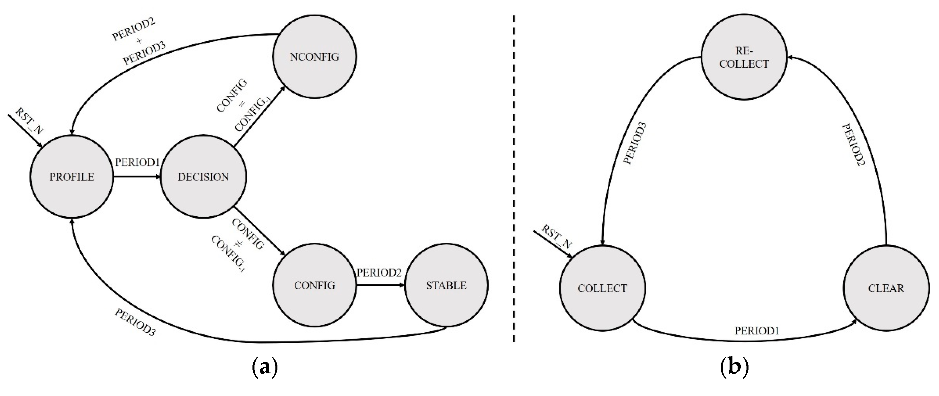
The state transition diagram of the adaptive controller is shown in Figure 9a. The cache is initialized to 16-way set-associative (maximum associativity) after the arrival of the RST_N signal. The state machine starts with the PROFILE state to wait for statistics from the performance monitor. After the duration of PERIOD1 (corresponding to reconfiguration period), the state transfers to DECISION. The adaptive controller determines the current optimal associativity. We compare whether the current optimal associativity is consistent with the last optimal associativity: The state transfers to CONFIG when inconsistent, the cache is controlled to tune associativity, and dirty blocks are written back after PERIOD2 (corresponding to the reconfiguration overhead). After the cache flush operation is completed, the state transfers to STABLE with the current optimal associativity. Then, the state returns to PROFILE. If the current and last associativity are consistent, the state returns to NCONFIG without any operation, returning to the PROFILE state after PERIOD2 + PERIOD3.
The performance monitor is implemented by counters, and the implementation of the high-performance counters is beyond the scope of this paper. Figure 9b shows the state transition diagram of the performance monitor. Counters are reset to 0 after the arrival of RST_N. The state machine starts with the COLLECT state, collecting application run time information. Then, the state transfers to the CLEAR state after PERIOD1. Run time information is stored to related registers, and counters are cleared to 0. After PERIOD2, the state transfers to RE-COLLECT to collect information during the stable-running period, which is used to evaluate the reconfiguration effect. Counters are reset to 0, and the state machine returns to the COLLECT state at the end of the stable-running period.
5. Results and Analysis
Software full-system simulation and hardware pre-synthesis simulation are performed for the proposed adaptive reconfigurable cache based on the decision tree (referred to as the DTARC in the following) in this paper.
5.1. Experimental Setup
In this paper, a multicore system with the proposed decision tree-based adaptive reconfigurable cache is built in the GEM5 simulator [22]. GEM5 is an open-source platform that is widely used in computer architecture research, encompassing system-level architecture as well as processor microarchitecture. It provides basic simulation objects, including a CPU, cache, on-chip network, memory, and other basic components, and it allows researchers to model modern computer hardware at the clock cycle level. It can also boot the Linux operating system to run a full-system simulation. Figure 10 depicts the abstraction level of the simulation system, with the real device in the solid line and the simulated device in the dashed line. The GEM5 simulator runs on real hardware with a host operating system. The multi-core system with the proposed reconfigurable cache is simulated by the GEM5, which corresponds to the simulated hardware in the figure. The benchmark runs in the GEM5 in full-system mode.
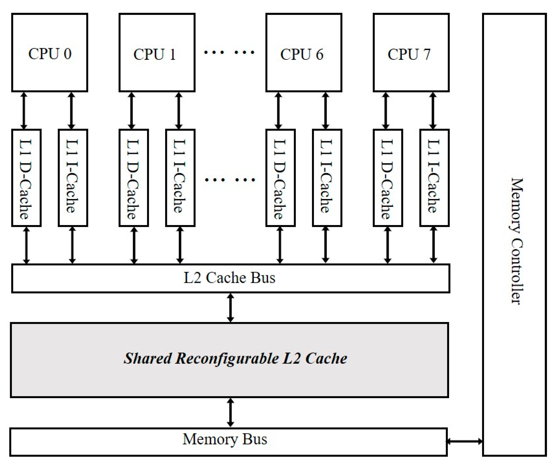
The detailed configuration of the GEM5 simulator is summarized in Table 1. The architecture of the build system is shown in Figure 11. The PARSEC benchmark [23] and SPLASH-2 benchmark [24] are employed to evaluate the performance of the proposed cache scheme. During simulation, only one application of the benchmark runs each time. Multiple threads with the same number of system cores are created for the running application and each thread is bound to a core of the system. All threads run in parallel. The simulation is terminated after the application enters the parallel stage and runs for 10 s (1 × 10¹⁰ clock cycles). In this paper, the simulation is performed with reconfiguration periods of 5 million clock cycles (C.C.), 10 million cycles (C.C.), 30 million cycles (C.C.), and 50 million cycles (C.C.) in the full-system mode. The decision-making period accounts for 10% of the reconfiguration period. The reconfiguration overhead is 500 clock cycles (C.C.).
5.2. Software Full-System Simulation Results and Analysis
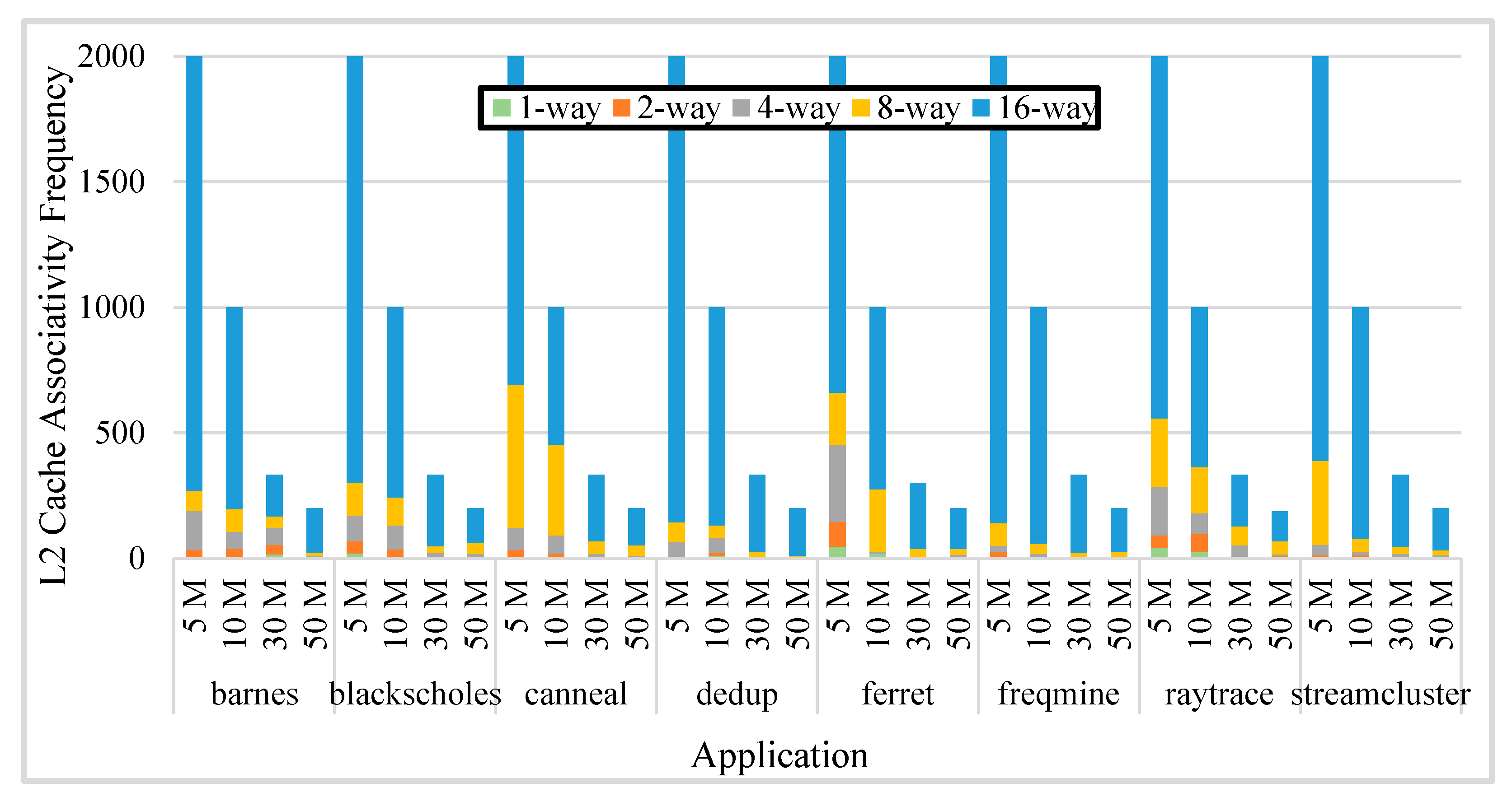
Figure 12 shows the number of occurrences of each associativity under different reconfiguration periods, which are respectively marked as 5 M, 10 M, 30 M, and 100 M. The 16-way set-associative cache appears the most frequently, followed by the 8-way set-associative cache. Generally, the larger associativity appears more frequently than the smaller associativity, because in most situations, large associativity reduces the miss rate and improves the performance of the last-level cache. When running with a smaller reconfiguration period, some applications use small associativity in some reconfiguration periods. This is because the shorter the reconfiguration period, the easier it is to recognize and capture the time-varying behavior of the application, and the more frequent associativity tuning. However, frequent tuning of the associativity wastes time in the dirty blocks writing back and cache flush options. Compulsory miss after flush will increase the miss rate, making the average memory access time longer, which may offset the performance gains benefit from reconfiguration and even lead to performance degradation.
To determine the optimal reconfiguration periods, it is necessary to compare the AMAT under different reconfiguration periods. The calculation method of L2 cache AMAT is revised to Equation (3) after considering the influence of reconfiguration overhead:
where the Average Config Time is the average reconfiguration overhead, calculated as in Equation (4):
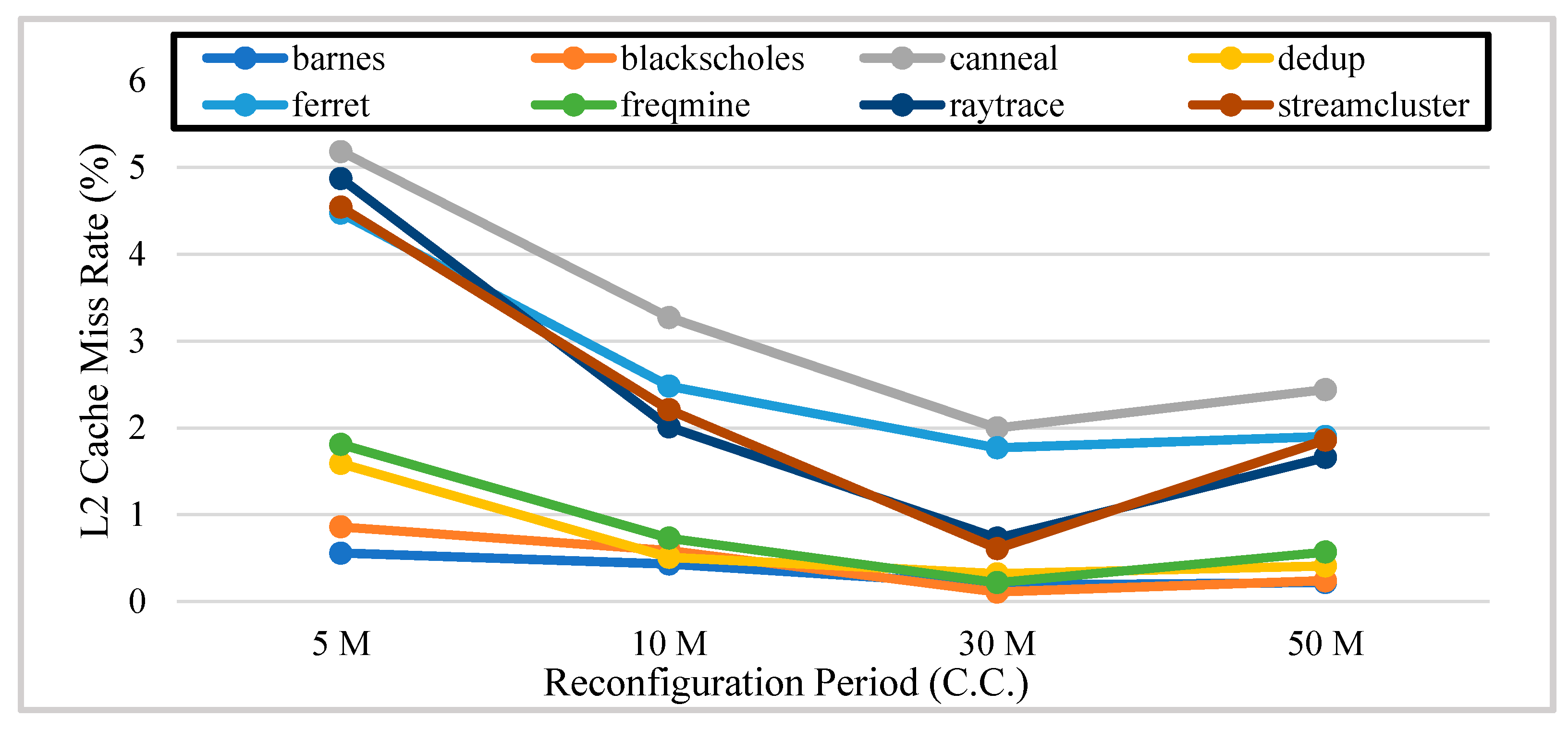
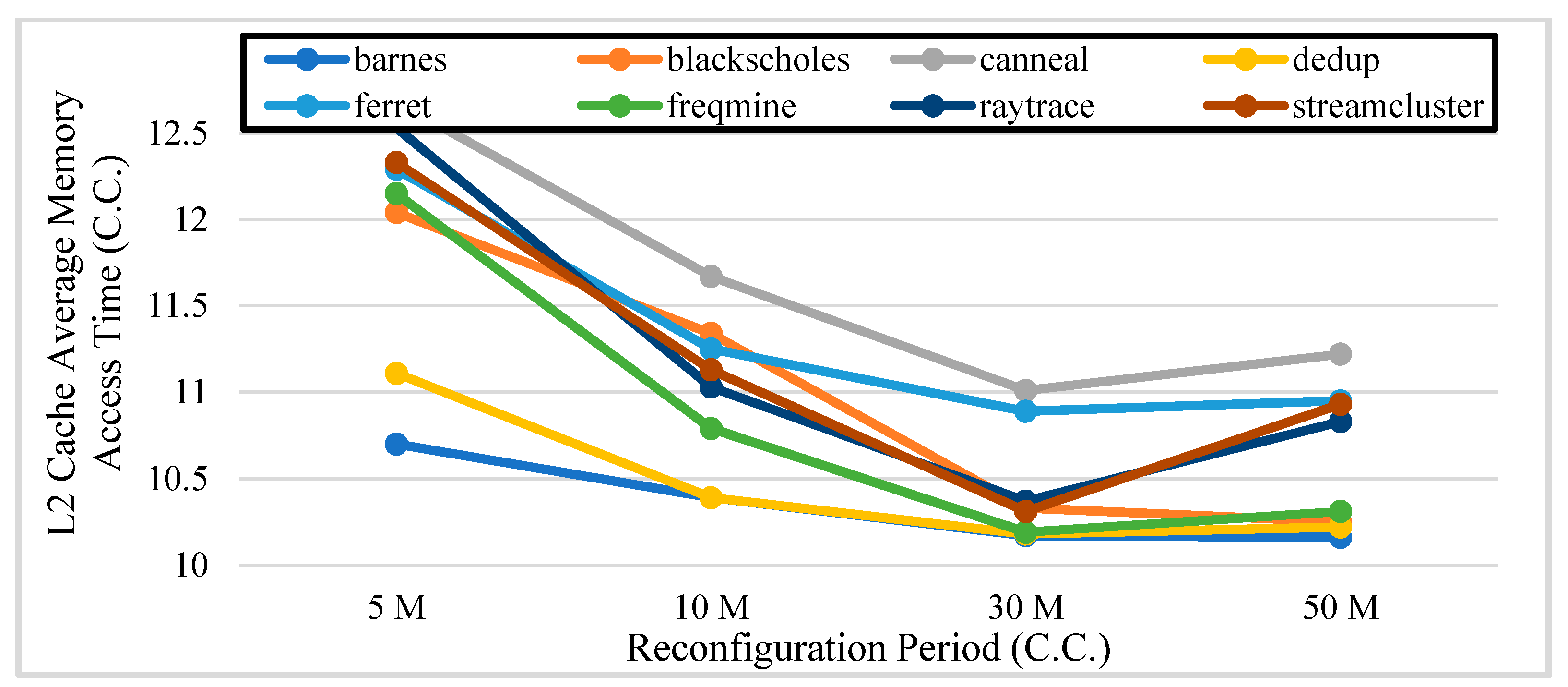
where the Config Penalty represents the reconfiguration overhead, including dirty blocks writing back and cache flush, which is 500 clock cycles in this work; the Config Number is the number of L2 cache associativity reconfiguration; and the Total Access Number is the total number of L2 cache accesses during the reconfiguration period. Figure 13 and Figure 14 show the L2 cache miss rate and L2 cache AMAT under different reconfiguration periods, respectively.
It can be seen from Figure 13 that the overall miss rate first decreases as the reconfiguration period increases. The miss rate drops to a minimum at 30 million clock cycles, and the miss rate of 50 million clock cycles is slightly larger than the miss rate at 30 million clock cycles. When the reconfiguration period is smaller, the reconfiguration of associativity becomes more frequent. After the associativity tuning, cache flush introduces a large number of compulsory misses and increases the miss rate. The reconfiguration overhead offsets the reduction in miss rate, benefiting from reconfiguration at 50 million clock cycles. It can be seen from Figure 14 that the AMAT of the L2 cache decreases significantly as the reconfiguration period becomes longer. Similarly, it is increased again at 50 million clock cycles except for the case of the application of Barnes and Blackscholes. Combining the above analysis, the optimal reconfiguration period of the system is determined to be 30 million clock cycles.
5.3. Hardware Pre-Synthesis Simulation Results and Analysis
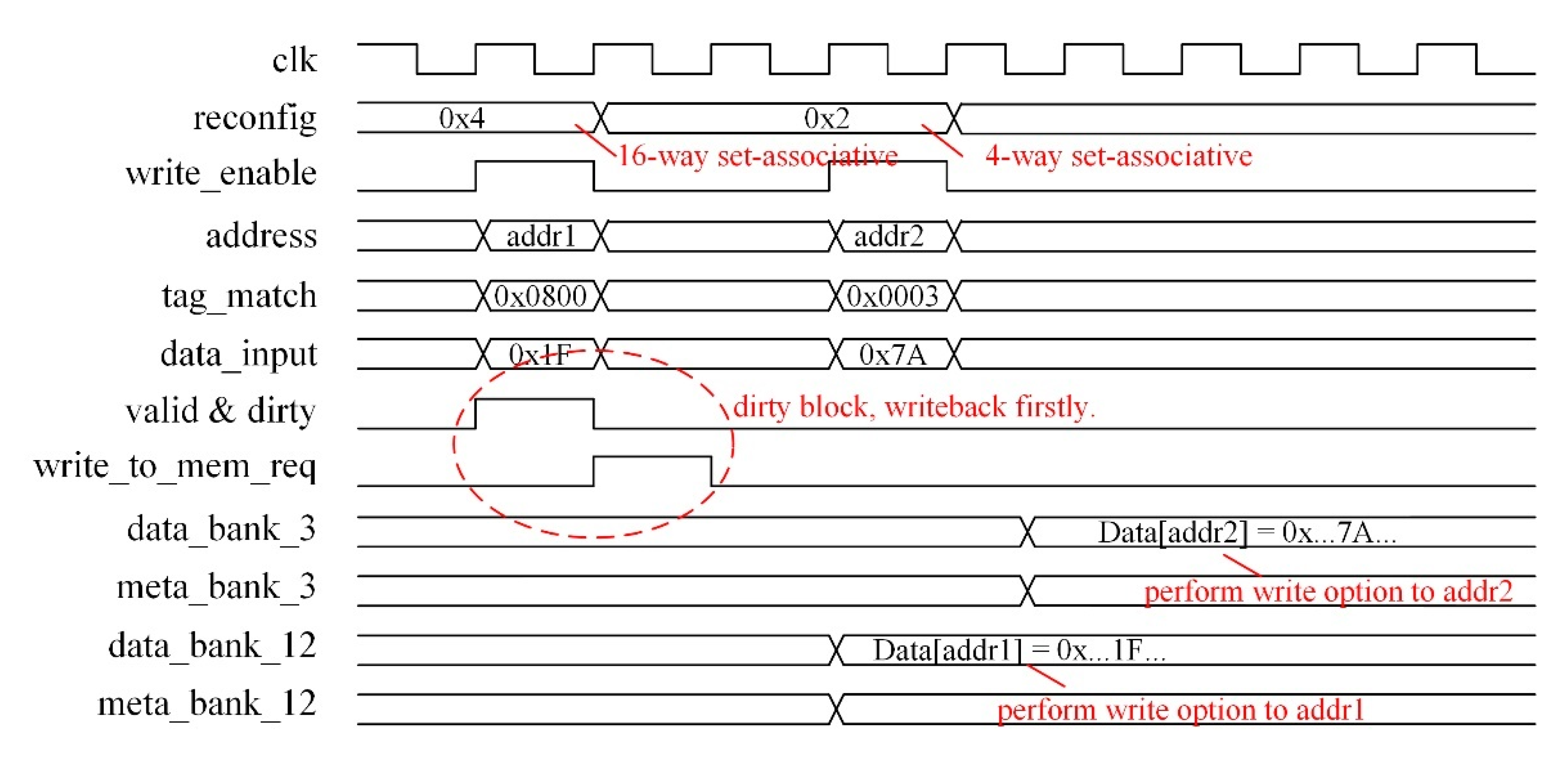
To ensure the design achieves the intended function, we perform a pre-synthesis simulation on the key modules using the Synopsys Verilog Compile Simulator. Taking the write operation as an example, the data are written to the cache under 16-way set-associative, 8-way set-associative, 4-way set-associative, 2-way set-associative, and direct-mapped, respectively. For convenience, Figure 15 shows the waveform when the cache is written under 16-way set-associative and 4-way set-associative; as we can see, the data are written to the correct address after the associativity is tuned.
To evaluate hardware overhead, we perform logic synthesis to the designed reconfiguration control logic (adaptive controller and performance monitor) using Synopsys Design Compiler under the TSMC 28 nm process. The results show that the total area of the reconfiguration control logic is 2902 um2.
5.4. Complexity and Overhead
The computational complexity of training a decision tree (the J48 algorithm) is O (n·m·log n), where n is the number of samples in the training set, and m is the number of attributes. The computational complexity of using the decision tree model to determine the optimal associativity (the proposed adaptive control algorithm) is O (d), where d is the max depth of the decision tree.
The implementation of adaptive reconfigurable cache comes with additional performance and hardware overhead.
From the performance perspective, the decision-making process of the optimal associativity is independent of the running of the application; thus, the decision-making process does not harm the performance of the application. According to the trained decision tree model, each decision of the optimal associativity takes at most three comparisons to reach a leaf node, and each comparison takes one clock cycle; therefore, the decisions will be made within three clock cycles. However, the tuning of the associativity leads to performance loss from two aspects:
- Reconfiguration overhead: This is an intuitive performance loss. During reconfiguration, the adaptive reconfiguration controller sends an interruption to the CPU to block the current operating until the cache finishes writing back dirty blocks and flushing. Each reconfiguration takes 500 clock cycles.
- Compulsory cache miss: After reconfiguration, all cache blocks are in an invalid state, and the temporary increase in cache miss rate caused by this increases the AMAT.
As analyzed in Section 3.2, the performance is related to the reconfiguration period. The performance gains brought by the adaptive tuning of the associativity should be greater than the performance loss caused by the reconstruction so that the overall performance of the system can be improved. From the perspective of hardware overhead, the additional hardware overhead for the real-time adaptive reconfigurable cache comes from two key modules:
- Performance monitor: To obtain the runtime statistics required for decision-making, three additional 32-bit counters need to be allocated to each core to save the IPC, total memory access, and miss rate parameters of the current reconfiguration period. Therefore, for a multi-core system with 8 cores, a total of 24 additional 32-bit counters are required.
- Adaptive controller: The adaptive controller is implemented by FSM, and the decision of the optimal associativity is realized by a three-level conditional judgment statement.
The hardware implementation of the related modules is relatively easy. The area of the synthesized hardware circuit is used to evaluate the complexity of the hardware implementation, and the results are shown in detail in Section 5.3.
5.5. Comparison
To evaluate the performance improvement of the proposed DTARC, we compared the following three caches in the multicore system:
- DTARC: The proposed adaptive reconfigurable cache is based on the decision tree algorithm.
- MRARC [6]: The adaptive control algorithm works by the following process. If the miss rate is beyond the system threshold, the associativity is tuned up one or two levels. We re-implement this approach in the multicore system.
- Basic cache: A fixed 16-way set-associative cache. According to Figure 12, this associativity appears most frequently across all applications.
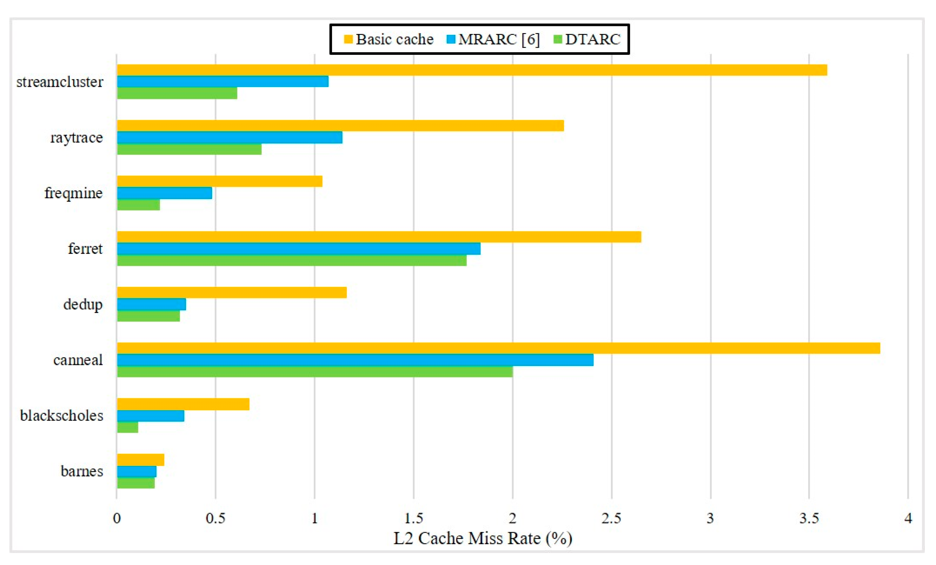
Figure 16 shows the miss rate results in different cache schemes under the optimal reconfiguration period. The L2 cache miss rate of the proposed adaptive reconfigurable cache in this paper is lower than that of the fixed 16-way set-associative cache in most instances except for in the case of the application of Barnes and Blackscholes. Compared with the fixed 16-way set-associative cache, the miss rate of the DTARC system is reduced by 60.97% on average across all applications, while the miss rate of MRARC [6] is reduced by 47.16% on average.
We compare the AMAT of different caches under the optimal reconfiguration period in Table 2. The performance improvements compared to the basic cache are in parentheses. Although the adaptive reconfigurable cache based on decision tree proposed in this paper compromises the performance of the applications of Barnes and Blackscholes, it provides performance improvements for other applications. Compared with the fixed 16-way set-associative cache, the DTARC obtains an AMAT reduction of up to 12.59% (in the application of Streamcluster) and 4.69% on average across all applications. By contrast, the MRARC in [6] only improves the performance by 2.50% compared with the fixed 16-way set-associative cache. Our reconfigurable adaptive cache scheme based on the decision tree outperforms the MRARC [6] and fixed 16-way set-associative cache. It can also be seen that although the miss rate of the L2 cache is significantly reduced, the resulting AMAT improvement is not as significant. This is because the L2 Hit Time of the system “dilutes” the performance improvement benefit from the miss rate reduction, as shown in Equation (3).
From the above analysis, it can be seen that for most applications, the miss rate and average memory access time of the proposed DTARC outperform the fixed 16-way and MRARC cache. The adaptive reconfigurable cache based on the decision tree achieves the design purpose.
The hardware cost of the proposed scheme under the TSMC 28 nm process is 2902 um2, which is comparable to that of the MRARC in [6] with an area of 3047 um2.
6. Conclusions
In this paper, we propose a novel decision tree-based adaptive associativity reconfigurable cache scheme. The scheme leverages the time-varying behavior of applications and adopts a decision tree to dynamically tune the cache associativity at runtime to reduce the average memory access time of the cache. Firstly, the optimal associativity scheme of the cache is obtained. Then, the decision tree model on optimal associativity is trained. Finally, by monitoring the behavior of the application at runtime, this decision tree model is used for adaptive control of cache associativity. We implemented the proposed scheme in the GEM5 simulator. The simulation results show that, compared with the reconfigurable cache based on the miss rate-threshold and the cache with fixed associativity, the scheme proposed in this work can effectively reduce the average memory access time and improve the system performance while maintaining low hardware overhead.
Author Contributions
Funding acquisition, Supervision, X.Z.; Methodology, Software, Investigation, W.Z.; Writing—original draft preparation, W.Z.; writing—review and editing, X.Z. All authors have read and agreed to the published version of the manuscript.
Funding
This research was funded by National Natural Science Foundation of China (NSFC), grant number 61525401.
Institutional Review Board Statement
Not applicable.
Informed Consent Statement
Not applicable.
Data Availability Statement
Not applicable.
Conflicts of Interest
The authors declare no conflict of interest.
References
- Hennessy, J.L.; Patterson, D.A. Computer Architecture: A Quantitative Approach, 5th ed.; Elsevier: Amsterdam, The Netherlands, 2011; pp. 71–144. [Google Scholar]
- Adegbija, T.; Gordon-Ross, A.; Munir, A. Dynamic phase-based tuning for embedded systems using phase distance mapping. In Proceedings of the 2012 IEEE 30th International Conference on Computer Design (ICCD), Montreal, QC, Canada, 30 September–3 October 2012; pp. 284–290. [Google Scholar]
- El-Sayed, N.; Mukkara, A.; Tsai, P.-A.; Kasture, H.; Ma, X.; Sanchez, D. KPart: A hybrid cache partitioning-sharing technique for commodity multicores. In Proceedings of the 2018 IEEE International Symposium on High Performance Computer Architecture (HPCA), Vienna, Austria, 24–28 February 2018; pp. 104–117. [Google Scholar]
- Aupy, G.; Benoit, A.; Goglin, B.; Pottier, L.; Robert, Y. Co-Scheduling HPC Workloads on Cache-Partitioned CMP Platforms. In Proceedings of the 2018 IEEE International Conference on Cluster Computing (CLUSTER), Belfast, UK, 10–13 September 2018; pp. 348–358. [Google Scholar]
- Gordon-Ross, A.; Vahid, F.; Dutt, N.D. Fast Configurable-Cache Tuning with a Unified Second-Level Cache. IEEE Trans. Very Large Scale Integr. Syst. 2009, 17, 80–91. [Google Scholar] [CrossRef] [Green Version]
- Xie, J.; Zhang, Y.; Wang, Q. The Design of Reconfigurable Cache Scheme in Multi-core Processor. Microelectron. Comput. 2016, 33, 1–5. [Google Scholar]
- Hsu, P.-Y.; Hwang, T. Thread-criticality aware dynamic cache reconfiguration in multi-core system. In Proceedings of the 2013 IEEE/ACM International Conference on Computer-Aided Design (ICCAD), San Jose, CA, USA, 18–21 November 2013; pp. 413–420. [Google Scholar]
- Huang, Y.; Mishra, P. Vulnerability-aware energy optimization using reconfigurable caches in multicore systems. In Proceedings of the 2017 IEEE International Conference on Computer Design (ICCD), Boston, MA, USA, 5–8 November 2017; pp. 241–248. [Google Scholar]
- Huang, Y.; Mishra, P. Reliability and energy-aware cache reconfiguration for embedded systems. In Proceedings of the 2016 17th International Symposium on Quality Electronic Design (ISQED), Santa Clara, CA, USA, 15–16 March 2016; pp. 313–318. [Google Scholar]
- Ahmed, A.; Huang, Y.; Mishra, P. Cache Reconfiguration Using Machine Learning for Vulnerability-aware Energy Optimization. ACM Trans. Embed. Comput. Syst. 2019, 18, 15. [Google Scholar] [CrossRef]
- Charles, S.; Ahmed, A.; Ogras, U.Y.; Mishra, P. Efficient Cache Reconfiguration Using Machine Learning in NoC-Based Many-Core CMPs. ACM Trans. Des. Autom. Electron. Syst. 2019, 24, 60. [Google Scholar] [CrossRef]
- Wang, W.; Mishra, P.; Gordon-Ross, A. Dynamic Cache Reconfiguration for Soft Real-Time Systems. ACM Trans. Embed. Comput. Syst. 2012, 11, 28. [Google Scholar] [CrossRef]
- Chen, Y.-H.; Wu, A.C.-H.; Hwang, T. A Dynamic Link-latency Aware Cache Replacement Policy (DLRP). In Proceedings of the 26th Asia and South Pacific Design Automation Conference, Tokyo, Japan, 18–21 January 2021; pp. 210–215. [Google Scholar]
- Lee, B.; Kim, K.; Chung, E. Replacement Policy Adaptable Miss Curve Estimation for Efficient Cache Partitioning. IEEE Trans. Comput. Aided Des. Integr. Circuits Syst. 2018, 37, 445–457. [Google Scholar] [CrossRef]
- Warrier, T.S.; Anupama, B.; Mutyam, M. An application-aware cache replacement policy for last-level caches. In Proceedings of the International Conference on Architecture of Computing Systems, Prague, Czech Republic, 19–22 February 2013; pp. 207–219. [Google Scholar]
- Danielsson, J.; Jägemar, M.; Behnam, M.; Seceleanu, T.; Sjödin, M. Run-time cache-partition controller for multi-core systems. In Proceedings of the IECON 2019—45th Annual Conference of the IEEE Industrial Electronics Society, Lisbon, Portugal, 14–17 October 2019; pp. 4509–4515. [Google Scholar]
- Tsai, P.-A.; Beckmann, N.; Sanchez, D. Jenga: Software-defined cache hierarchies. In Proceedings of the 44th Annual International Symposium on Computer Architecture, Toronto, ON, Canada, 24–28 June 2017; pp. 652–665. [Google Scholar]
- Basireddy, K.R.; Singh, A.K.; Al-Hashimi, B.M.; Merrett, G.V. AdaMD: Adaptive Mapping and DVFS for Energy-Efficient Heterogeneous Multicores. IEEE Trans. Comput. Aided Des. Integr. Circuits Syst. 2020, 39, 2206–2217. [Google Scholar] [CrossRef] [Green Version]
- DiTomaso, D.; Sikder, A.; Kodi, A.; Louri, A. Machine learning enabled power-aware network-on-chip design. In Proceedings of the Design, Automation & Test in Europe Conference & Exhibition (DATE), Lausanne, Switzerland, 27–31 March 2017; pp. 1354–1359. [Google Scholar]
- Frank, E.; Hall, M.; Holmes, G.; Kirkby, R.; Pfahringer, B.; Witten, I.H.; Trigg, L. Weka—A machine learning workbench for data mining. In Data Mining and Knowledge Discovery Handbook; Springer: Berlin/Heidelberg, Germany, 2009; pp. 1269–1277. [Google Scholar]
- Aljawarneh, S.; Yassein, M.B.; Aljundi, M. An enhanced J48 classification algorithm for the anomaly intrusion detection systems. Clust. Comput. 2019, 22, 10549–10565. [Google Scholar] [CrossRef]
- Binkert, N.; Beckmann, B.; Black, G.; Reinhardt, S.K.; Saidi, A.; Basu, A.; Hestness, J.; Hower, D.R.; Krishna, T.; Sardashti, S. The gem5 simulator. ACM SIGARCH Comput. Archit. News 2011, 39, 1–7. [Google Scholar] [CrossRef]
- Bienia, C.; Li, K. Benchmarking Modern Multiprocessors; Princeton University: Princeton, NJ, USA, 2011. [Google Scholar]
- Woo, S.C.; Ohara, M.; Torrie, E.; Singh, J.P.; Gupta, A. The SPLASH-2 programs: Characterization and methodological considerations. In Proceedings of the 22nd Annual International Symposium on Computer Architecture, S. Margherita Ligure, Italy, 22–24 June 1995; pp. 24–36. [Google Scholar]
Figure 1.
Architecture of adaptive reconfigurable cache.

Figure 2.
Division of application running times.

Figure 3.
Optimal associativity search scheme.

Figure 4.
Decision tree model.

Figure 5.
Adaptive control workflow.

Figure 6.
False hit caused by associativity decrease.

Figure 7.
Associativity reconfigurable cache with a fixed size.

Figure 8.
Hardware architecture of associativity-reconfigurable cache.

Figure 9.
State transition diagrams: (a) state transition diagram of adaptive controller; (b) state transition diagram of performance monitor.
Figure 9.
State transition diagrams: (a) state transition diagram of adaptive controller; (b) state transition diagram of performance monitor.

Figure 10.
Abstraction level of the simulation system.

Figure 11.
Multicore system with the proposed decision tree-based adaptive reconfigurable cache.

Figure 12.
Associativity distribution.

Figure 13.
L2 cache miss rate of different reconfigurable periods.

Figure 14.
L2 cache AMAT of different reconfigurable periods.

Figure 15.
Waveform of cache write option.

Figure 16.
Miss rate of different L2 caches.


Table 1.
Configuration of the GEM5 simulator.
| CPU | ISA: X86-64 |
|---|---|
| 8 Cores/1 GHz | |
| L1 cache | private, fixed parameters |
| L1-I: 64 B/32 KB/4-way set-associative/1 clock cycle | |
| L1-D: 64 B/32 KB/4-way set-associative/1 clock cycle | |
| L2 cache | Shared, associativity reconfigurable |
| 64 B/4 MB/16,8,4,2,1-way set-associative/10 clock cycle | |
| Interconnect | Coherent Bus |
| Main memory | DDR3_1600_8 × 8 |
| 4 GB/50 clock cycle |
Table 2.
Average memory access time of different L2 caches.
| Application | Basic Cache (C.C.) | MRARC [6] (C.C.) | DTARC (C.C.) |
|---|---|---|---|
| Barnes | 10.12 | 10.14 (−0.20%) | 10.17 (−0.49%) |
| Blackscholes | 10.34 | 10.24 (0.99%) | 10.33 (0.10%) |
| Canneal | 11.93 | 11.69 (2.04%) | 11.01 (7.71%) |
| Dedup | 10.58 | 10.25 (3.17%) | 10.18 (3.78%) |
| Ferret | 11.33 | 11.29 (0.33%) | 10.89 (3.84%) |
| Freqmine | 10.52 | 10.34 (1.75%) | 10.19 (3.14%) |
| Raytrace | 11.13 | 10.80 (2.98%) | 10.37 (6.83%) |
| Streamcluster | 11.80 | 10.75 (8.87%) | 10.31 (12.60%) |
Publisher’s Note: MDPI stays neutral with regard to jurisdictional claims in published maps and institutional affiliations. |
© 2021 by the authors. Licensee MDPI, Basel, Switzerland. This article is an open access article distributed under the terms and conditions of the Creative Commons Attribution (CC BY) license (https://creativecommons.org/licenses/by/4.0/).
Share and Cite
MDPI and ACS Style
Zhu, W.; Zeng, X. Decision Tree-Based Adaptive Reconfigurable Cache Scheme. Algorithms 2021, 14, 176. https://0-doi-org.brum.beds.ac.uk/10.3390/a14060176
AMA Style
Zhu W, Zeng X. Decision Tree-Based Adaptive Reconfigurable Cache Scheme. Algorithms. 2021; 14(6):176. https://0-doi-org.brum.beds.ac.uk/10.3390/a14060176
Chicago/Turabian StyleZhu, Wei, and Xiaoyang Zeng. 2021. "Decision Tree-Based Adaptive Reconfigurable Cache Scheme" Algorithms 14, no. 6: 176. https://0-doi-org.brum.beds.ac.uk/10.3390/a14060176
Note that from the first issue of 2016, this journal uses article numbers instead of page numbers. See further details here.