Angle-Dependent Absorption of Sound on Porous Materials


1
Lumir Oy, Tammiston Kauppatie 22, 01510 Vantaa, Finland
2
Aalto Acoustics Lab, Department of Signal Processing and Acoustics, School of Electrical Engineering, Aalto University, P.O. Box 13100, 00076 Aalto, Finland
3
Department of Bioproducts and Biosystems, School of Chemical Engineering, Aalto University, P.O. Box 16300, 00076 Aalto, Finland
*
Author to whom correspondence should be addressed.
Acoustics 2020, 2(4), 753-765; https://0-doi-org.brum.beds.ac.uk/10.3390/acoustics2040041
Submission received: 31 August 2020
/
Revised: 30 September 2020
/
Accepted: 12 October 2020
/
Published: 16 October 2020
(This article belongs to the Special Issue Innovative Design and Applications of Materials for Acoustically Performative Indoor and Outdoor Environments)
Abstract
:Sound-absorbing materials are usually measured in a reverberation chamber (diffuse field condition) or in an impedance tube (normal sound incidence). In this paper, we show how angle-dependent absorption coefficients could be measured in a factory-type setting. The results confirm that the materials have different attenuation behavior to sound waves coming from different directions. Furthermore, the results are in good agreement with sound absorption coefficients measured for comparison in a reverberation room and in an impedance tube. In addition, we introduce a biofiber-based material that has similar sound absorption characteristics to glass-wool. The angle-dependent absorption coefficients are important information in material development and in room acoustics modeling.
1. Introduction
Distinctive modern architecture from schools and offices to private houses is currently dominated by large open spaces, such as open-plan offices and multi-functional learning spaces. Such spaces set very high acoustical requirements for the surface materials in order to make the spaces suitable for their functions. Thus, the acoustic material needs to absorb sound from nearby and faraway sound sources, i.e., the sounds reach the acoustic surfaces at very high and low angles. Understanding the angular dependence of the sound absorption mechanisms would provide us with a tool to develop better designs for large open spaces.
The most important acoustical property of a porous material is its ability to absorb sound. The sound absorption mechanisms in porous materials may differ according to their porous structure, which is determined by the manufacturing process and by the raw materials used in their production. For conventional materials that dominate the acoustic market (wool, foams, and perforated boards) extensive researched has been conducted and their mechanisms of sound-energy dissipation are well understood [1]. However, new materials have being developed, and different mechanisms of sound absorption have been reported; some examples can be found in the literature for activated carbon [2], natural fibers [3,4], and metamaterials [5,6]. Of especial interest is the increasing development of bio-acoustic materials [7] that have equal or even superior acoustic properties to the conventional materials, but that additionally contribute to mitigating climate change by reducing CO emissions, and even, in the case of wood-based building materials, binding CO into their structures for their operating life. Merely by replacing 1 % of the worlds porous acoustic panel market (approx. 220 billion m2/year in 2017) with a biofiber-based solution, over 3000 tons of CO could be bound to buildings, which roughly equals the emissions from travelling by airplane for over 20 million kilometers [8].
The standardised measurement techniques can measure the sound absorption coefficients in a diffuse field in a reverberation room (ISO-354 [9]) or for a perpendicular plane wave using an impedance tube (ISO-10534-2 [10]). No standard method for angle-dependent absorption measurement exists, however, some measurement procedures have been developed to determine sound absorption in situ [11,12,13,14,15], and these methods, in general, can be used to determine the angle-dependent sound absorption coefficients. A good review of different methods and techniques to measure sound absorption for oblique sound incidence is presented by Brandão [16].
Although angle-dependent sound absorption measurement techniques are not established, there are widely used methods for describing the distribution of reflected energy in space, i.e., measuring scattering and diffusion coefficients [17]. The scattering coefficient [18] is defined as the ratio of the non-specularly reflected sound energy to the total reflected energy. Thus, the scattering coefficient is a single value, averaging spatial distribution, possibly at octave or one-third octave bands. The diffusion coefficient [19,20] is also a single value at given frequency bands, but it describes the uniformity of the polar response. Both of these coefficients are used in room acoustics modeling programs and to describe the quality of diffusors, but they do not tell anything on the absorption of sound of the measured surface.
The method for measuring both diffusion and scattering coefficients requires measurements of reflected sound energy in multiple directions for a sound wave hitting the sample from a certain direction. This measurement is repeated from multiple incoming directions to cover all oblique directions. In this paper, we harness a similar measurement technique to study the angle-dependent absorption, instead of scattering, of various materials with different sound absorption mechanisms: solid, perforated and porous panels. The studied materials are commercially available acoustic products, with the bioboard as an exception. We use the method described in AES-4id-2001 [19] for the determination of the spatial distribution of the first sound reflections from the studied surfaces and to generate their polar responses. The generated polar responses are used to compute the angle-dependent sound absorption coefficients. Our results confirm that the technique presented here is robust, since they are in good agreement with the sound absorption coefficients measured in a reverberation room and in an impedance tube. The angle-dependent sound absorption coefficients are valuable data in room acoustics modeling and for developers of the absorption materials.
2. Materials and Methods
2.1. Studied Material Samples
In this study, we demonstrate the measurements and results of the angle-dependent absorption coefficients with four different materials. The materials are mounted with an overall depth of system (o.d.s.) of approximately 50 mm. A 13-mm plain gypsum panel was used as the reference material. The materials are listed in Table 1. The perforated gypsum, stone-wool and glass-wool are off-the-shelf materials; only the bioboard is novel and not as well known. The bioboard is a biofiber-based acoustic panel that consists mainly of wood-based cellulosic fibers and biobased binders. Thus, it is an environmentally friendly porous material that could be used similarly to glass- and stone-wools. Unlike the conventional biofiber products, such as paper or cardboard, the bioboard acoustic panels store the atmospheric CO to the building for decades in a similar way to wooden structures. The measured bioboard samples were produced during process development tests in a semi-industrial pilot facility. The production process of bioboard was designed according to the principles of circular economy and is planned to be scaled up to industrial production in the near future.
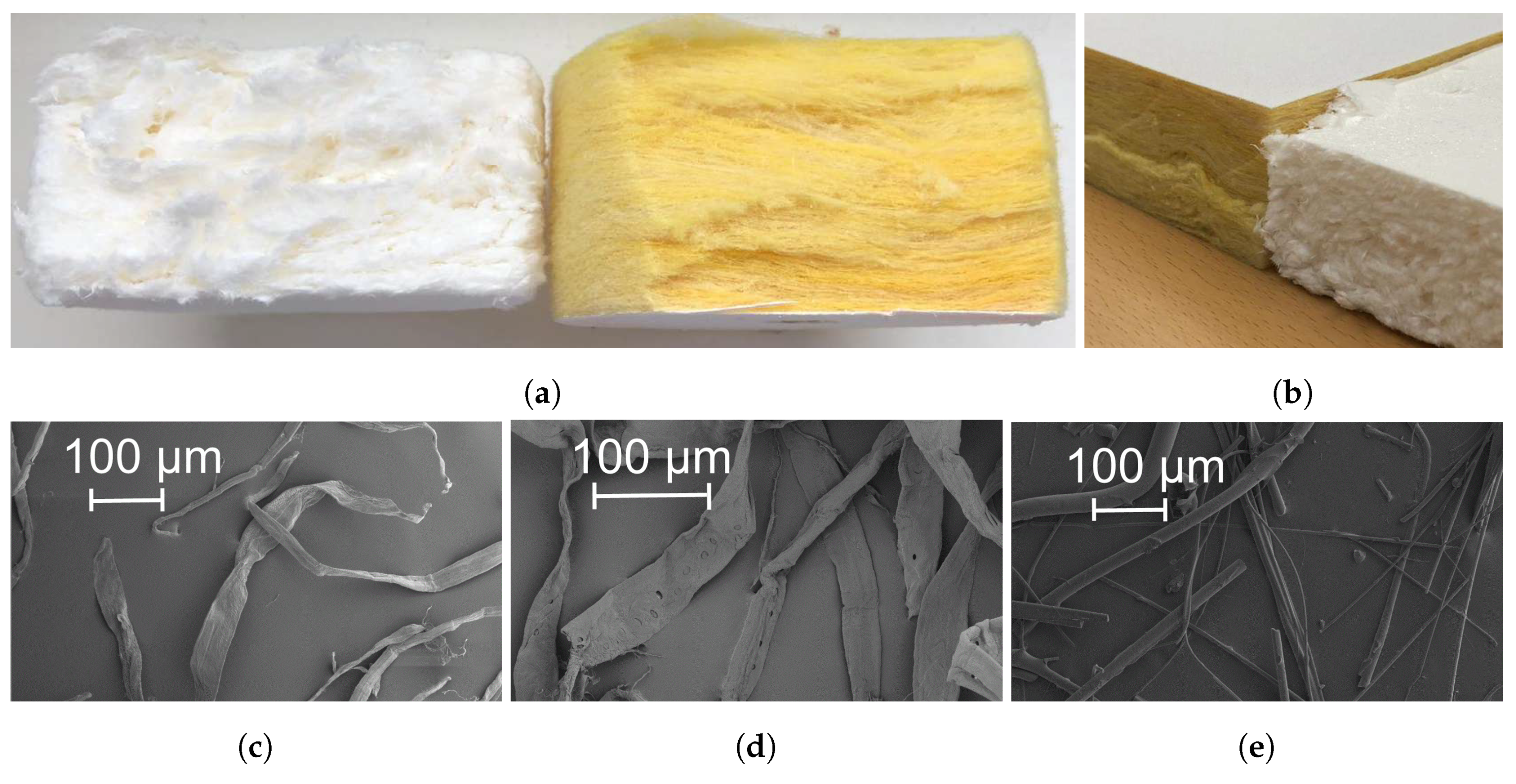
Figure 1a,b shows the cross-sectional porous structure of the two porous absorbers, glass-wool and bioboard. Notable differences are clearly seen. Glass-wool fibers are arranged in well-defined layers of fibers, whereas the cellulose fibers in bioboard are arranged in aggregates of fibers, forming layers. Moreover, some larger pores can be detected between aggregates of cellulose fibers. The differences in the porous structure of the two materials is due to the manufacturing process as well as the properties of the fibers. The bioboard panels were produced through foam-forming technology [21]. Such a technique involves the mixing of fibers, water and surfactant together with other chemicals to provide fire-retardant, aesthetic and desired mechanical properties to the panels. As a result, a fibrous suspension is generated with bubbles that prevent fibers, to some degree, from flocculating. The bulky structure is then produced by drying the wet foam. The aggregation of fibers that can be identified in the porous structure of the bioboard panel is attributed to the tendency of native cellulose fibers to build flocs in suspensions. The propensity of fibers to flocculate is mainly determined by the length, coarseness, curl and flexibility of the fibers, with the fiber length being the most relevant parameter [22,23]. The longer the fibers, the greater the number of contacts per fiber, and thus greater flocs form. Curled fibers entangle more easily than straight ones. Coarseness affects the stiffness of fibers in bending: the finer the fibers, the easier for them to bend, thus facilitating flocculation. In fiber foam, the movement of fibers is restricted by the bubbles, and thus flocculation effects are reduced [24]. However, flocs still occur at spaces between bubbles. The raw fibers used for the production of the bioboard panels were a mixture of dissolving birch and bleached pine pulp fibers. The physical properties of the wood fibers were measured with the help of a Kajaani FiberLab optical fiber analyser (Metso automation, Finland), and the results are reported in Table 2. Scanning electron microscopy images of the wood fibers and glass-wool are shown in Figure 1c–e.
2.2. Experimental Setup
The spatial distribution of the first sound reflections from the studied materials, i.e., the polar responses, was determined according to the method described in AES-4id-2001 [19]. The polar responses were obtained in a single plane using a 2D-goniometer, as shown in Figure 2. In this setup, half of the semicircle was used for the receiver array, and the other half for the sound source. A total of 16 omnidirectional measurement microphones (1/4-inch, model Superlux ECM-999) were fixed to the semicircle with an angle interval of 5, from 10 to 85. Shock mounts were used for all the microphones to prevent transmission of structural vibrations. The sound source, YAMAHA HS5, had a flat frequency response (74 to 24 kHz, at −3 dB), and it was movable between 0 and 85. Four angles of sound incidence, 30, 45, 60, and 75 were considered sufficient for the purpose of this study. The distance between the microphones and source to the sample under test was two meters.
The dimensions of the measured panels were 0.5 × 0.5 m. The size of the panel has a significant effect on the measurements of diffusion coefficient [19]. In the measurements of angle-dependent sound absorption conducted in this work, the size of the panel sets the limits of the method at low frequencies. Increasing the size of the panels has two main effects: firstly, it moves the low-frequency limit to be lower in frequency, and secondly, it makes the diffraction effect from the edges less prominent compared to the surface scattering from the test panel, however, larger samples require greater distances between the receiver positions and the sample under test [19]. The panels were placed on a sample holder of dimensions 0.5 × 0.5 m and adjustable height. Only one panel for each of the materials was measured. All the panels were mounted in a wooden frame (0.5-cm thick), and attached on top of the gypsum board sample. Two wooden frames were built, one for the perforated boards and the other for the porous absorbers. The height of the perforated panels frame was 37 mm, and the panels were placed on top of the frame, without any glue or mechanical attachment. For the porous materials, the height of the frame was 50 mm and it surrounded the material. Once the sample was mounted, the height of the sample-holder was adjusted to have the top surface of the panels at a height of 1.5 m.
With the dimensions of this setup, the reflections from the floor are the first spurious reflection arriving at the microphones after the sound reflected from the panel under test. The measurement setup with the dimensions is illustrated in Figure 3. Only one panel for each of the materials was measured. The measurements were conducted under the same environmental conditions, i.e., the same room temperature and the same relative humidity.
2.3. Compensation of the Measurement Device Responses and Generation of Polar Responses
The first reflection (and diffraction from the edges) from the surface under test is acquired with the help of a sound source to irradiate the test surface, and microphones to measure impulse responses at each position of observation. Signal-processing techniques are employed to separate the reflection of interest from the direct sound and spurious reflections from floor and room surfaces and the equipment used in the measurements. The open-source MATLAB Toolbox—ITA [26]—was used to measure the impulse responses using the logarithmic sine sweep technique [27], in the frequency range from 20 Hz to 10 kHz. The sweep was 6-s long with a 2-s interval between measurements, and the impulse responses were obtained as the average of three measurements. Background noise levels were measured during the measurements using a sound analyser Norsonic Nor140, and they are reported in Table 3. An impulse response () for each sound reflection angle (16 in total) was measured for each of the panels. Another impulse response () (again, to all 16 directions) was measured without the sample holder installed in the measuring position. All the measured impulse responses, () and (), were de-convolved with the loudspeaker-microphone response (), which was measured by placing the loudspeaker at the sample position and tilting it to match its on-axis response with the on-axis responses of the microphones. The responses () were not measured to all 16 angles, only to angles 15, 30, 45, 60 and 75. Thus, the response of the reflection from the panel under test is computed as
and this computation is repeated to all 16 directions. As () was measured only to five directions; the de-convolution was performed with the directions listed in Table 4.
The signal processing for the acquisition of involves the following steps. First, all the measured impulse responses are temporally aligned. The alignment is performed by determining the beginning of the impulse responses in accordance with standard ISO 3382-1 ([28], Section A.3.4). The direct sound and spurious reflections in are eliminated by subtracting from . Then, the first reflections from the panel under test are windowed. The window used here was a 250-sample-long rectangular window ( = 44.1 kHz) with the edges of a hamming window starting 15 samples before the arrival of the first reflection from the panel. Smoothing the edges of the rectangular window avoids the high-frequency oscillation typical of a rectangular window. Then, the direct sound in is windowed with a 250-sample rectangular window with Hamming edge only at the end of the window. This length of window limits the low-frequency of the results down to approximately 200–300 Hz.
The windowed impulse responses and are Fourier transformed, and their spectrum is smoothed by averaging in a one-third-octave band. is then calculated by de-convoluting the loudspeaker-microphone response from in the frequency domain. Finally, the third-octave levels in decibels are obtained from as the power of the numerical integration of the spectral points lying in each third-octave band of interest. These third-octave levels are used to generate the polar responses. Figure 4 shows an example of the signal-processing analysis carried out to obtain at 60 sound incidence and 85 observation position for two panels: plain gypsum and bioboard.
2.4. Computation of the Angle-Dependent Absorption Coefficients
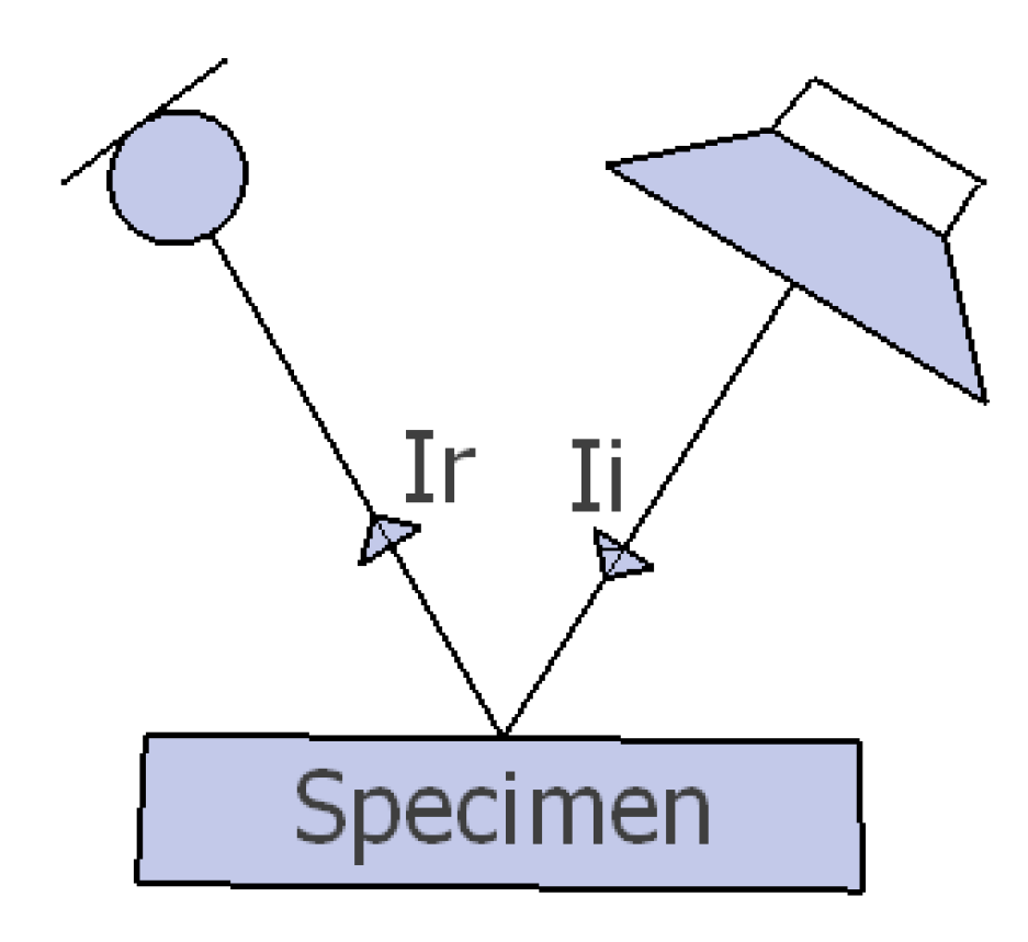
The determination of the angle-dependent sound absorption coefficients is based on the definition of sound absorption shown in Figure 5 and Equation (2), which expresses sound absorption, , as the ratio between the reflected and the incident sound energy.
Assuming a perfect reflector with equal dimensions than the specimen under test and mounted in the same frame, it follows that
where and are the sound energy reflected from the perfect reflector and the specimen under test measured at the receiver position. and are the incident sound energy to the specimen and reflected sound energy from the specimen, respectively. The measurements can be considered as free field measurements, as the first reflection from the panels is windowed from other room reflections, as explained earlier. Hence, sound intensity can be expressed as a function of sound pressure
where p is sound pressure, is density of air, c is speed of sound, and is the reference intensity. Now, Equation (2) can be rewritten as
and with sound pressure levels as
where is the attenuation of sound energy, D, given by the material under test with respect to the perfect reflector.
In these measurements, a plain gypsum panel was considered to be sufficiently reflective at the frequencies of interest. Therefore, it was used as the perfect reflector panel, referred to from now on as the reference panel (REF). The attenuation of sound energy given by the material under test with respect to the reference material integrated over all the microphone positions is calculated as
where n is the number of microphones in the microphone array; are the responses of the isolated reflections from the panel to all 16 directions as given by Equation (1). Finally, the angle-dependent sound absorption coefficients are calculated as
3. Results
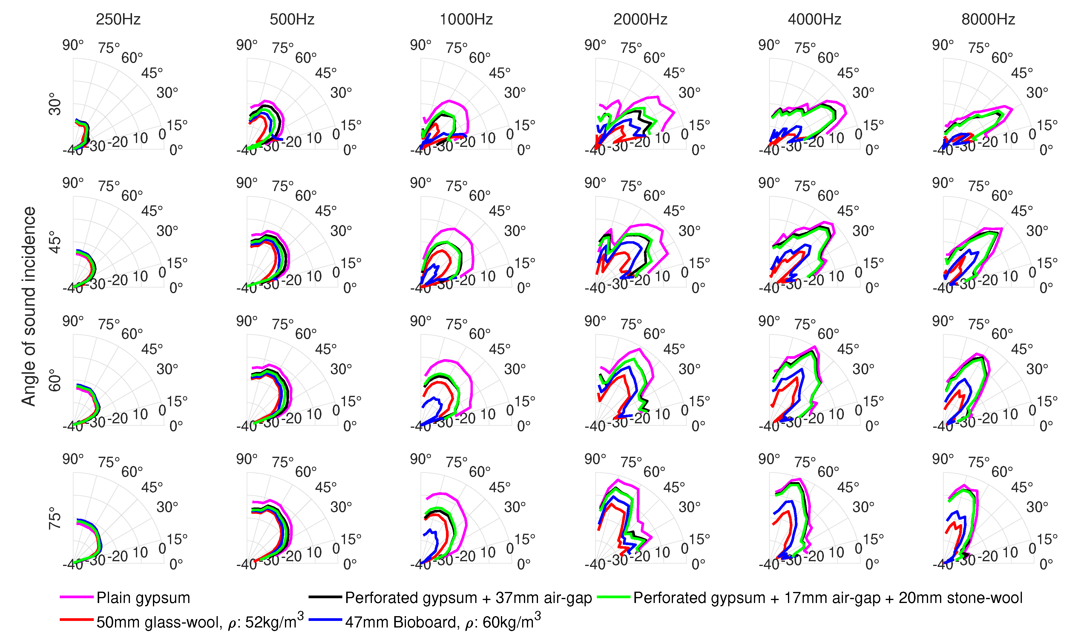
The polar responses illustrating the spatial distribution of sound energy reflected from the panels under test are shown in Figure 6. The maximum sound pressure among all the materials and microphones was obtained for the third-octave frequency band centered at 4000 Hz for the plain gypsum panel, at 60 sound incidence and receiver angle. The levels shown in the polar responses are normalized to this maximum sound pressure. The low-frequency limit of these results extends down to approximately 200–300 Hz. This limit is defined by the length of the window used to isolate the first reflections from the panels, as well as the panel size.
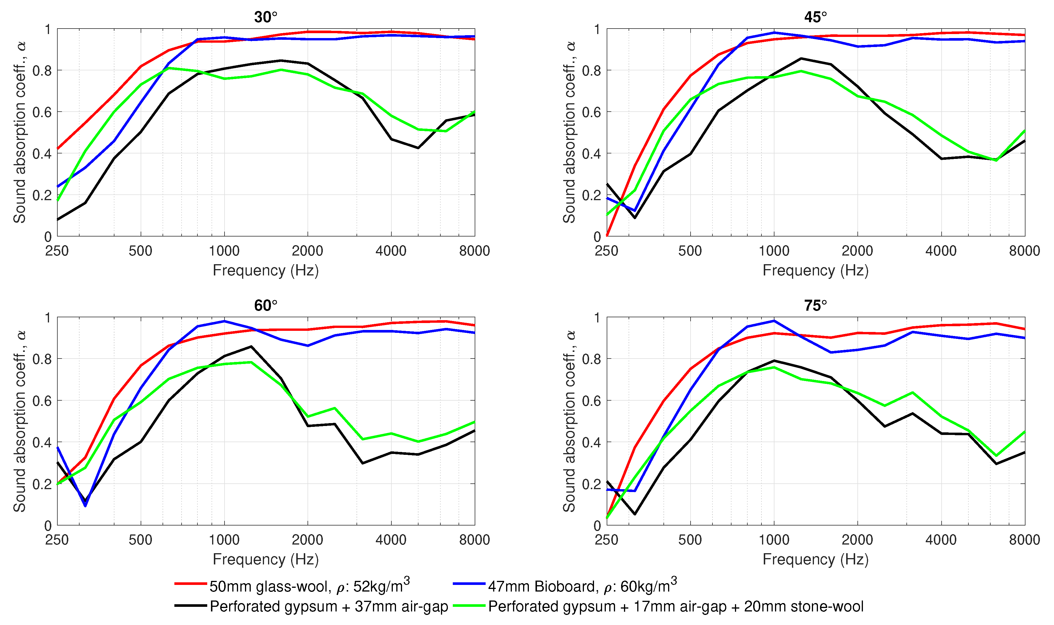
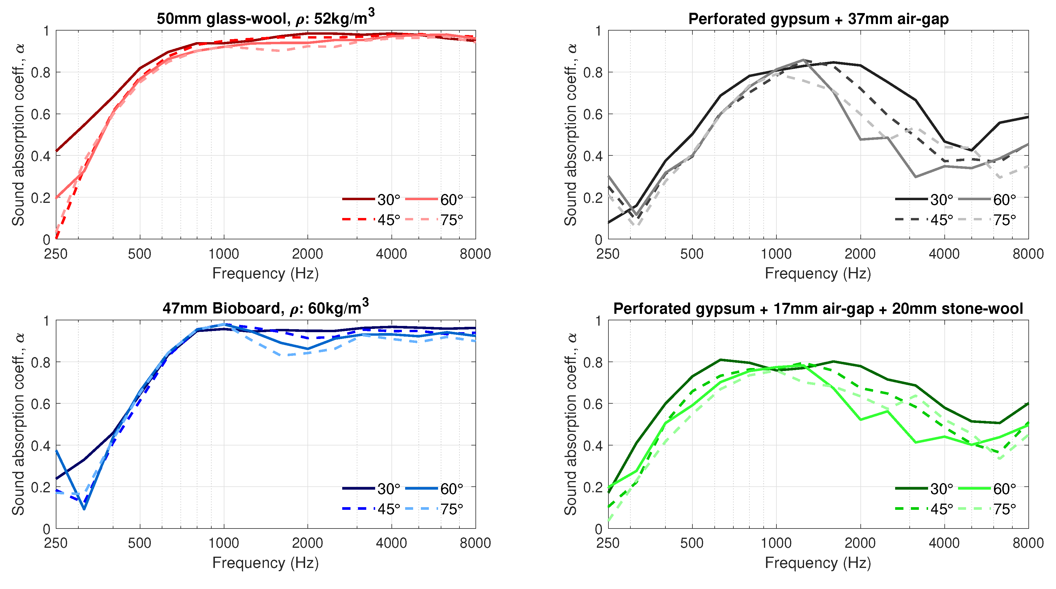
The performance of the materials in terms of the incidence-angle-dependent sound absorption is shown in Figure 7 and Figure 8. Figure 7 compares the sound absorption coefficients of the four measured materials at each angle of sound incidence. It is noted that data from the receiver at have been excluded from the polar responses and angle-dependent sound absorption calculations due to difficulties in the separation of the direct sound and spurious reflections from the first reflection from the panel under test. Figure 8 plots the same data, one material at a time, to illustrate changes in the sound absorption coefficients of each material for different angles of sound incidence.
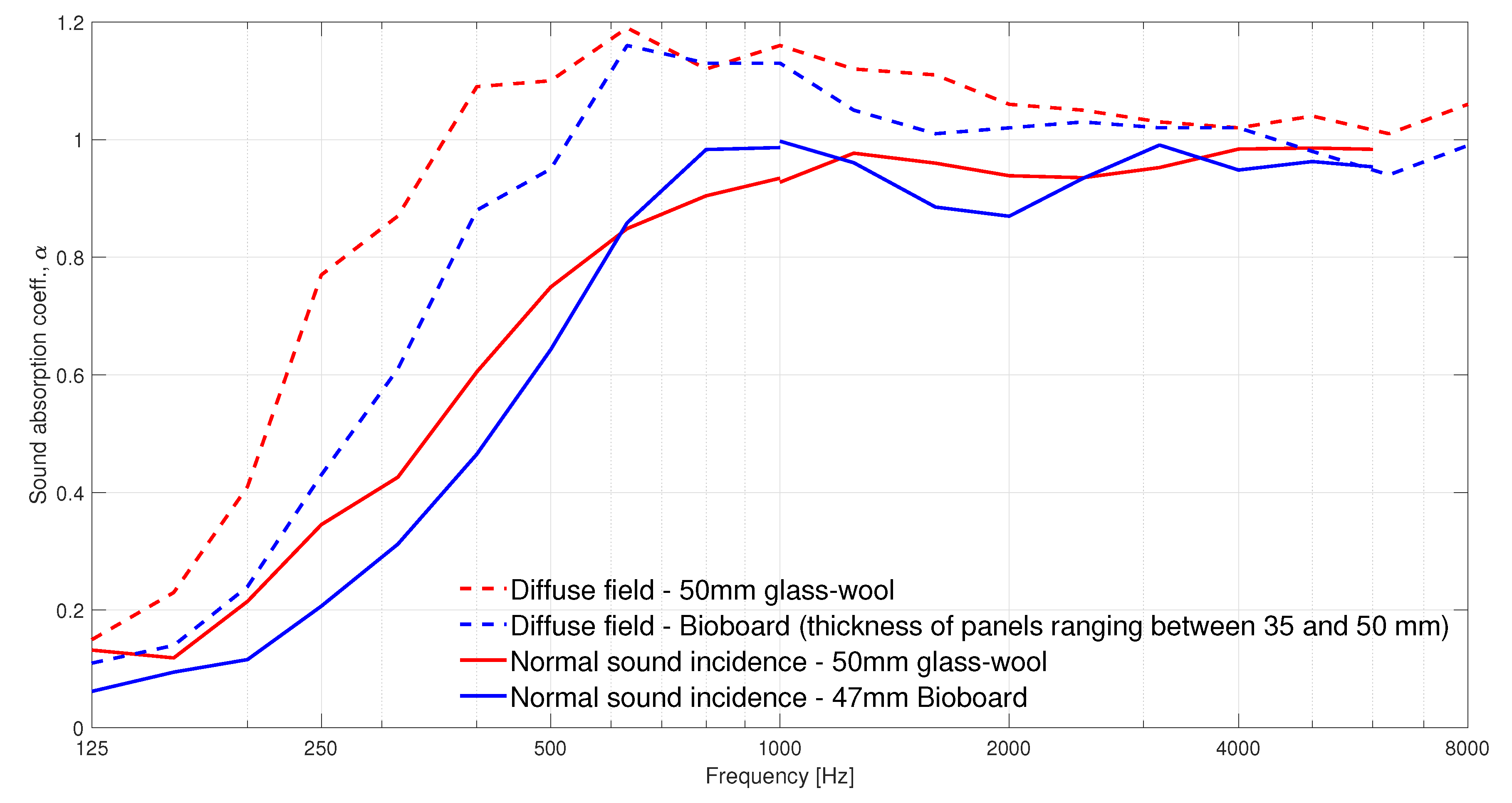
For comparison, we measured the two absorption materials also in the diffuse field and in the impedance tube to show the diffuse field and 90 incidence angle absorption coefficients. Figure 9 presents the results of these measurements.
4. Discussion
The distribution of sound energy reflected from all the panels is rather similar for all the materials as seen in Figure 6. Only the levels are different, as expected from flat panels. At frequencies higher than 1000 Hz, most of the reflected sound energy goes to the specular zone, which is the natural reflection pattern of plain boards. At frequencies below 1000 Hz, the distance between the sample and the microphones is not sufficiently large, and so the measurements are considered as near-field measurements. As a result, all the microphones are inside the specular zone, and therefore sound energy is almost equally dispersed to all the microphones. This could be fixed by increasing the distance between the microphones and the panels, so that some of the microphones stay outside the specular zone [1]. It is also noted that, as frequency decreases, less sound is reflected and more sound is diffracted around the panels due to the relatively small panel size. The combined effects of sound absorption from the panel, diffraction, as well as the transition from far-field to near-field measurements explain why the sound levels measured for all the absorbers at 1000 Hz are lower than those measured at 500 Hz.
In general, as shown in Figure 7 and Figure 8, the deviation in the sound absorption coefficients measured for the incidence angles 30, 45, 60 and 75 are rather small. However, the difference at the lower frequencies increases with increasing off-normal incidence angle. Similar results have been reported in [29]. Another relevant difference in the angle-dependent measurements is the change in the angle of sound incidence in the dip appearing at 2000 Hz for the bioboard sample. Such fluctuations are typical in normal incidence sound-absorption measurements, and they tend to disappear in diffuse field measurements, as seen in Figure 9. Figure 8 reveals that those dips also tend to vanish with decreasing angle of sound incidence.
The angle-dependent sound-absorption curves of the perforated board with a 37-mm air-gap behind exhibit a resonance centered at around 1250 Hz; see Figure 7 and Figure 8. When a 20-mm stone wool panel is placed behind the board, the resonance is broadened and its center is moved to lower frequencies. The results also show that the resonance, with and without wool behind the perforated panel, is remarkably broadened for lower angles of sound incidence. Furthermore, at angle of sound incidence, a second resonance appears at around 3000 Hz. These results agree well with the diffuse sound absorption coefficients provided by the manufacturer of the perforated boards in [30].
A comparison between the two porous absorbers, bioboard and glass-wool, shows three regions where the sound absorption properties of the materials differ slightly. At frequencies below 700 Hz and above 1200 Hz, glass-wool dissipates sound energy more efficiently. In contrast, in the frequency range extending from 700 to 1200 Hz, bioboard outperforms the glass-wool panel. This behaviour is also seen in the impedance tube measurements (Figure 9). At this frequency range, the bioboard shows a peak which most probably is related to the destructive interference occurring at the surface of the material between the direct and the reflected sound waves coming from the rigid backing behind the sample. This resonance is typical for granular materials where the visco-thermal losses taking place within the material are not sufficient to completely attenuate the sound wave being reflected from the rigid backing behind the sample [31,32]. However, in this case, a bioboard can be considered as a fibrous-granular porous material that, as seen in Figure 7 and Figure 8, significantly improves the typical sound absorption properties given by granular materials. This is attributed to the increasing viscous-thermal losses introduced by the fibrous aggregates. In the future development of bioboard-like materials, the sound absorption properties could be optimized by adjusting the thickness and the size of the pores, so that viscous-thermal losses combined with the resonance effect would provide the maximum absorption.
5. Conclusions
For room acoustics modeling and for material development purposes, angle-dependent absorption coefficients are needed. In this paper, we demonstrated one way to measure such coefficients for often-used absorption materials and one novel biobased material. The results revealed that angle-dependent absorption measurements fit well between the normal incidence angle (impedance tube) and diffuse field (reverberation room) results. When the incoming sound angle approaches the normal incidence, the absorption curves resemble the impedance tube results and the grazing angle results converge to diffuse field results. The understanding of angular sound dissipation of absorption materials help in the development of novel materials and help to design them more accurately.
Author Contributions
Conceptualization, J.C. and T.H.; Measurements and analysis, J.C.; Writing—original draft preparation, J.C.; Writing—review and editing, J.C., T.H. and T.L.; Visualization, J.C. and T.L.; Supervision, T.H. and T.L. All authors have read and agreed to the published version of the manuscript.
Funding
This research was partially funded by Business Finland research grant (2218/31/2018).
Acknowledgments
The authors gratefully acknowledge the contribution of Marko Makkonen, Hannes Hynninen, Kari Kammiovirta and Jonna Rajaharju from Lumir Oy (Finland) for the development of the measuring device, the supplying of the bioboard samples, and their help in the measurements. The authors also would like to show their gratitude to Julie Meyer from the Acoustic Lab. of Aalto University for her contribution in the design of the measurement system. The authors would like to express their gratitude to Kristiina Lillqvist for taking the scanning electron microscopy images. The authors also would like to give thanks to Ecophon Finland and Knauf Danoline Finland for supplying the panels used in these measurements.
Conflicts of Interest
The authors declare no conflict of interest.
Abbreviations
The following abbreviations are used in this manuscript:
| MDPI | Multidisciplinary Digital Publishing Institute |
| ISO | International Standard Organization |
| CO | Carbon dioxide |
| AES | Audio Engineering Society |
| ITA | Institute of Technical Acoustics, Aachen, Germany |
| O.d.s. | Overall depth of system |
References
- D’Antonio, P.; Cox, T. Acoustic Absorbers and Diffusers: Theory, Design and Application; Taylor & Francis: Abingdon, UK, 2004. [Google Scholar]
- Venegas, R.; Umnova, O. Influence of sorption on sound propagation in granular activated carbon. J. Acoust. Soc. Am. 2016, 140, 755–766. [Google Scholar] [CrossRef] [PubMed] [Green Version]
- Berardi, U.; Iannace, G. Acoustic characterization of natural fibers for sound absorption applications. Build. Environ. 2015, 94, 840–852. [Google Scholar] [CrossRef]
- Berardi, U.; Iannace, G. Predicting the sound absorption of natural materials: Best-fit inverse laws for the acoustic impedance and the propagation constant. Appl. Acoust. 2017, 115, 131–138. [Google Scholar] [CrossRef]
- Jiménez, N.; Romero-García, V.; Pagneux, V.; Groby, J.P. Rainbow-trapping absorbers: Broadband, perfect and asymmetric sound absorption by subwavelength panels for transmission problems. Sci. Rep. 2017, 7, 13595. [Google Scholar] [CrossRef] [PubMed]
- Tang, Y.; Ren, S.; Meng, H.; Xin, F.; Huang, L.; Chen, T.; Zhang, C.; Lu, T.J. Hybrid acoustic metamaterial as super absorber for broadband low-frequency sound. Sci. Rep. 2017, 7, 43340. [Google Scholar] [CrossRef] [PubMed] [Green Version]
- Arenas, J.P.; Asdrubali, F. Eco-materials with noise reduction properties. In Handbook of Ecomaterials; Martinez, L.M.T., Kharissova, O.V., Kharisov, B.I., Eds.; Springer International Publishing: Cham, Switzerland, 2019; pp. 3031–3056. [Google Scholar]
- Ciers, J.; Mandic, A.; Toth, L.D.; Op’t Veld, G. Carbon Footprint of Academic Air Travel: A Case Study in Switzerland. Sustainability 2019, 11, 80. [Google Scholar] [CrossRef] [Green Version]
- ISO 354. Acoustics—Measurements of Sound Absorption in a Reverberation Room; ISO: Geneva, Switzerland, 2003. [Google Scholar]
- ISO 10534-2. Acoustics—Determination of Sound Absorption Coefficient and Impedance in Impedance Tubes—Part 2: Transfer-Function Method; ISO: Geneva, Switzerland, 1998. [Google Scholar]
- Mommertz, E. Angle-dependent in-situ measurements of reflection coefficients using a subtraction technique. Appl. Acoust. 1995, 46, 251–263, Building Acoustics. [Google Scholar] [CrossRef]
- Nocke, C. In-situ acoustic impedance measurement using a free-field transfer function method. Appl. Acoust. 2000, 59, 253–264. [Google Scholar] [CrossRef]
- Garai, M. Measurement of the sound-absorption coefficient in situ: The reflection method using periodic pseudo-random sequences of maximum length. Appl. Acoust. 1993, 39, 119–139. [Google Scholar] [CrossRef]
- Nolan, M. Estimation of angle-dependent absorption coefficients from spatially distributed in situ measurements. J. Acoust. Soc. Am. 2020, 147, EL119–EL124. [Google Scholar] [CrossRef] [PubMed] [Green Version]
- Karjalainen, M.; Tikander, M. Reducing Artefacts of In-Situ Surface Impedance Measurements. Available online: http://pcfarina.eng.unipr.it/Public/Standing-Wave/ica01.pdf (accessed on 15 October 2020).
- Brandão, E.; Lenzi, A.; Paul, S. A Review of the In Situ Impedance and Sound Absorption Measurement Techniques. Acta Acust. United Acust. 2015, 101, 443–463. [Google Scholar] [CrossRef]
- Vorländer, M.; Mommertz, E. Definition and measurement of random-incidence scattering coefficients. Appl. Acoust. 2000, 60, 187–199. [Google Scholar] [CrossRef]
- ISO 17497-1. Acoustics—Sound-Scattering Properties of Surfaces—Part 2: Measurement of the Random-Incidence Scattering Coefficient in a Reverberation Room; ISO: Geneva, Switzerland, 2004. [Google Scholar]
- D’Antonio, P.; Cox, T. AES information document for room acoustics and sound reinforcement systems-characterization and measurement of surface scattering uniformity. J. Audio Eng. Soc. 2001, 49, 149–165. [Google Scholar]
- ISO 17497-2. Acoustics—Sound-Scattering Properties of Surfaces—Part 2: Measurement of the Directional Diffusion Coefficient in a Free Field; ISO: Geneva, Switzerland, 2012. [Google Scholar]
- Jahangiri, P.; Logawa, B.; Korehei, R.; Hodgson, M.; Martinez, D.M.; Olson, J.A. On acoustical properties of novel foam-formed cellulose-based material. Nord. Pulp Pap. Res. J. 2016, 31, 14–19. [Google Scholar] [CrossRef]
- Kerekes, R.J.; Schell, C.J. Effects of fiber length and coarseness on pulp flocculation. Tappi J.—(USA) 1995, 78, 133–139. [Google Scholar]
- Beghello, L.; Eklund, D. Some mechanisms that govern fiber flocculation. Nord. Pulp Pap. Res. J. 1997, 12, 119–123. [Google Scholar] [CrossRef]
- Lappalainen, T.; Lehmonen, J. Determinations of bubble size distribution of foam-fibre mixture using circular hough transform. Nord. Pulp Pap. Res. J. 2012, 27, 930–939. [Google Scholar] [CrossRef]
- Haimei, Z.; Ma, S.; Wu, Y. Building Materials in Civil Engineering; Elsevier: Amsterdam, The Netherlands, 2011; Volume 80, pp. 81–308. [Google Scholar]
- Berzborn, M.; Bomhardt, R.; Klein, J.; Richter, J.G.; Vorländer, M. The ITA-Toolbox: An open source MATLAB toolbox for acoustic measurements and signal processing. In Proceedings of the 43th Annual German Congress on Acoustics, Kiel, Germany, 6–9 March 2017; Volume 2017, pp. 6–9. [Google Scholar]
- Farina, A. Simultaneous measurement of impulse response and distortion with a swept-sine technique. In Audio Engineering Society Convention 108; Audio Engineering Society: New York, NY, USA, 2000. [Google Scholar]
- ISO 3382-1. Measurement of Room Acoustic Parameters—Part 1: Performance of Spaces; ISO: Geneva, Switzerland, 2009. [Google Scholar]
- Hald, J.; Song, W.; Haddad, K.; Jeong, C.H.; Richard, A. In-situ impedance and absorption coefficient measurements using a double-layer microphone array. Appl. Acoust. 2019, 143, 74–83. [Google Scholar] [CrossRef]
- Datasheet of Perforated Panels Provided by Their Manufacturer Knauf Danoline. Available online: https://knaufdanoline.com/wp-content/uploads/Data_sheet_Solopanel_UK.pdf (accessed on 31 August 2020).
- Yamaguchi, M.; Nakagawa, H.; Mizuno, T. Sound absorption mechanism of porous asphalt pavement. J. Acoust. Soc. Jpn. (E) 1999, 20, 29–43. [Google Scholar] [CrossRef] [Green Version]
- Swift, M.; Bris, P.; Horoshenkov, K. Acoustic absorption in re-cycled rubber granulate. Appl. Acoust. 1999, 57, 203–212. [Google Scholar] [CrossRef]
Figure 1.
(a,b) illustrates the cross-sectional porous structure of bioboard and glass-wool, for the impedance tube samples, and the samples used for the determination of incidence angle-dependent sound absorption coefficients. (c–e) show scanning electron microscopy images of dissolving hardwood, bleached softwood and glass fibers, respectively.

Figure 2.
The applied measurement system (on the left). The loudspeaker can be moved on rails from 0 to 85 and there are 16 microphones at 5 spacing, from 10 to 85. On the right, the measured materials are shown and the porous materials were mounted in a wooden frame, seen top right.
Figure 2.
The applied measurement system (on the left). The loudspeaker can be moved on rails from 0 to 85 and there are 16 microphones at 5 spacing, from 10 to 85. On the right, the measured materials are shown and the porous materials were mounted in a wooden frame, seen top right.

Figure 3.
Dimensions and arrangement of the receiver array and the sound source in the measuring device.
Figure 3.
Dimensions and arrangement of the receiver array and the sound source in the measuring device.

Figure 4.
The process to extract the reflection from the panel under test. On the left, responses measured for a gypsum panel; on the right, responses measured for a bioboard panel.
Figure 4.
The process to extract the reflection from the panel under test. On the left, responses measured for a gypsum panel; on the right, responses measured for a bioboard panel.

Figure 5.
Incident and reflected sound energy from a specimen, and , respectively.

Figure 6.
One-third octave polar responses at selected center frequencies for four angles of sound incidence 30, 45, 60 and 75. The circles (starting from the x-axis) indicate the levels in decibels.
Figure 6.
One-third octave polar responses at selected center frequencies for four angles of sound incidence 30, 45, 60 and 75. The circles (starting from the x-axis) indicate the levels in decibels.

Figure 7.
Sound absorption coefficients at one-third octave bands, measured for four angles of sound incidence 30, 45, 60 and 75.
Figure 7.
Sound absorption coefficients at one-third octave bands, measured for four angles of sound incidence 30, 45, 60 and 75.

Figure 8.
Sound absorption coefficients at one-third octave bands, measured for four angles of sound incidence 30, 45, 60 and 75.
Figure 8.
Sound absorption coefficients at one-third octave bands, measured for four angles of sound incidence 30, 45, 60 and 75.

Figure 9.
Normal sound incidence and diffuse field sound absorption coefficients measured with an impedance tube and in a reverberation room, respectively. The materials investigated are bioboard (blue lines) and 50-mm glass-wool (red lines). The thickness of the bioboard panels differ between 35 and 50 mm. The normal sound incidence sound absorption coefficients were measured with a large impedance tube for the frequency range 125–1000 Hz, and with a small impedance tube for the frequency range 1000–6000 Hz (note that 6000 Hz is the cut-off frequency of the small impedance tube).


Table 1.
Investigated materials. The overall depth for all the structures was approximately 50 mm, except for the plain gypsum.
Table 1.
Investigated materials. The overall depth for all the structures was approximately 50 mm, except for the plain gypsum.
| Material | Manufacturer | o.d.s. | Density | % of Perforation |
|---|---|---|---|---|
| Plain gypsum | Knauf | 13 mm | ||
| Knauf | 13 mm + | Square 8 mm, 20% | ||
| 37 mm air-gap | ||||
| Perforated gypsum | Knauf | 13 mm + | Square 8 mm, 20% | |
| 17 mm air-gap + | ||||
| 20 mm stone wool | ||||
| Glass-wool | Ecophon | 50 mm | 52 kg/m | |
| Bioboard | Lumir | 47 mm | 60 kg/m |
Table 2.
Physical properties of the wood fibers used in the production of the bioboard panels. The reported fiber length is the length-weighted average fiber length. Length and width of glass fibers are reported for comparison [25].
Table 2.
Physical properties of the wood fibers used in the production of the bioboard panels. The reported fiber length is the length-weighted average fiber length. Length and width of glass fibers are reported for comparison [25].
| Fiber Type | Length (mm) | Width (m) | Curl (%) |
|---|---|---|---|
| 0.73 | 16.32 | 17.7 | |
| 1.97 | 25.36 | 15.4 | |
| 50–150 | 12 |
Table 3.
Background noise levels during the measurements. Measurements obtained using a sound analyser Norsonic Nor140.
Table 3.
Background noise levels during the measurements. Measurements obtained using a sound analyser Norsonic Nor140.
| Central Frequencies of the Octave Frequency Bands (Hz) | 125 | 250 | 500 | 1000 | 2000 | 4000 | 8000 |
|---|---|---|---|---|---|---|---|
| (dB) | 43.2 | 38.6 | 36.3 | 30.8 | 23.4 | 15.6 | 14.4 |
Table 4.
The applied directions in de-convolution of .
| 10, 15, 20 | 15 |
| 25, 30, 35 | 30 |
| 40, 45, 50 | 45 |
| 55, 60, 65 | 60 |
| 70, 75, 80 | 75 |
Publisher’s Note: MDPI stays neutral with regard to jurisdictional claims in published maps and institutional affiliations. |
© 2020 by the authors. Licensee MDPI, Basel, Switzerland. This article is an open access article distributed under the terms and conditions of the Creative Commons Attribution (CC BY) license (http://creativecommons.org/licenses/by/4.0/).
Share and Cite
MDPI and ACS Style
Cucharero, J.; Hänninen, T.; Lokki, T. Angle-Dependent Absorption of Sound on Porous Materials. Acoustics 2020, 2, 753-765. https://0-doi-org.brum.beds.ac.uk/10.3390/acoustics2040041
AMA Style
Cucharero J, Hänninen T, Lokki T. Angle-Dependent Absorption of Sound on Porous Materials. Acoustics. 2020; 2(4):753-765. https://0-doi-org.brum.beds.ac.uk/10.3390/acoustics2040041
Chicago/Turabian StyleCucharero, Jose, Tuomas Hänninen, and Tapio Lokki. 2020. "Angle-Dependent Absorption of Sound on Porous Materials" Acoustics 2, no. 4: 753-765. https://0-doi-org.brum.beds.ac.uk/10.3390/acoustics2040041