Article

Plane and Surface Acoustic Waves Manipulation by Three-Dimensional Composite Phononic Pillars with 3D Bandgap and Defect Analysis

Department of Architecture and Civil Engineering, City University of Hong Kong, Kowloon 999077, Hong Kong SAR, China
*
Author to whom correspondence should be addressed.
Submission received: 1 December 2020 / Revised: 22 December 2020 / Accepted: 5 January 2021 / Published: 8 January 2021
(This article belongs to the Special Issue Acoustical Materials)

Abstract

:
The current century witnessed an overwhelming research interest in phononic crystals (PnCs) and acoustic metamaterials (AMs) research owing to their fantastic properties in manipulating acoustic and elastic waves that are inconceivable from naturally occurring materials. Extensive research literature about the dynamical and mechanical properties of acoustic metamaterials currently exists, and this maturing research field is now finding possible industrial and infrastructural applications. The present study proposes a novel 3D composite multilayered phononic pillars capable of inducing two-dimensional and three-dimensional complete bandgaps (BGs). A phononic structure that consisted of silicon and tungsten layers was subjected to both plane and surface acoustic waves in three-dimensional and two-dimensional periodic systems, respectively. By frequency response study, the wave attenuation, trapping/localization, transmission, and defect analysis was carried out for both plane and surface acoustic waves. In the bandgap, the localized defect state was studied for both plane and surface acoustic waves separately. At the defect state, the localization of both plane and surface acoustic waves was observed. By varying the defect size, the localized frequency can be made tailorable. The study is based on a numerical technique, and it is validated by comparison with a reported theoretical work. The findings may provide a new perspective and insight for the designs and applications of three-dimensional phononic crystals for surface acoustic wave and plane wave manipulation, particularly for energy harvesting, sensing, focusing and waves isolation/attenuation purposes.

1. Introduction

The past two decades observed an overwhelming research interest for phononic crystals (PnCs) and locally resonant acoustic metamaterials (AMs) for their marvelous acoustic and elastic wave manipulation properties that are inconceivable from naturally occurring materials. Such properties include but are not limited to acoustic waveguiding and filtering [1,2], sound insulation [3,4], superlens [5], sensing [6], wave-multiplexing [7,8], focusing and lensing [9], acoustic and elastic cloaking [10,11], topological insulators [12,13,14,15], actively tunable and controllable AMs [16] and seismic shielding [17,18,19,20,21], etc. The rapid research progress reported fantastic dynamic characteristics and effective medium properties for AMs that include negative mass density [22,23], negative moduli [24], negative Poisson’s ratio [25], double negativity [26], negative bulk modulus/compressibility [27], kirigami effects [28], and other peculiar mechanical properties that were once imagined to be inconceivable. Such research innovations are a pathway towards novel meta-devices with potential industrial and infrastructure applications, including vibration suppression [29,30,31], sound insulation [3,4], automotive applications [32], meta-bearing housing design [33], thermal-acoustic devices [34], underwater acoustics [35,36], earthquake applications [17,18,19,20], etc. For a detailed review, one can refer to Muhammad and Lim [37] and Wang et al. [38].
One prominent characteristic of PnCs and AMs is the presence of the frequency bandgap (BG), a frequency region where wave propagation is prohibited. The position, range, and type of BG depend upon lattice design and structural composition. Starting from the holey silicon substrate with Bragg scattering BG [39] to locally resonant AMs [40], multiple structural configurations are reported for different types of waves, including Lamb wave [41] and surface acoustic wave (SAW) [42,43]. A number of researchers have demonstrated the dynamic physical properties from BG [44] to subwavelength focusing [45], MEMS applications [46], waveguiding and multiplexing [8], acoustic rainbow trapping [47], and cloaking [10,11]. Multiple lattice designs have been reported. Among those studies, elastic pillars on thin-plate [7,30,48] and semi-infinite substrate/half space [8,40,49] have caught the attention of the phononic community for their simple structural design and subwavelength BG properties. The phenomena of local resonance BG generation by coupling of pillar resonance and Lamb waves in thin-plate structures was studied by Pennec et al. [50,51] and Wu et al. [52,53]. Later, in another study, Wu et al. [53] experimentally demonstrated such BGs in an aluminum pillar-plate structure. Further, the tunable local resonance BG in sonic regime [54] and high transmission losses sonic insulator were also reported [55]. Furthermore, multiple works [7,8,50,51] on elastic waveguiding via line or point defect in PnCs lattice and/or by varying pillar diameter, height, or material properties in a row of periodic pillars were presented. The defect mode frequency can be tuned by filling the hollow pillar part with some liquid [56,57]. In another work, Jin et al. [7] studied the whispering gallery mode of pillar-plate setup for elastic waveguiding. Besides, Bilal et al. [48] modified the pillar-plate structure and investigated the trampoline effect for BG enlargement. Similarly, Muhammad and Lim studied multi-resonant trampoline pillared metamaterial [30] and whispering gallery modes resulting from the localized cavity modes of the hollow pillars upon interaction with surface wave [8] for subwavelength waveguiding and wave multiplexing effects. Furthermore, Wang et al. [52] reported with experiments the waveguiding characteristic in a stubbed PnC plate by a bent waveguide that changes the wave direction towards the ultrasonic regime.
SAW manipulation in ultrasonic regimes also caught the attention of the phononic community for various applications such as sensing, waveguiding and filtration, etc. In this context, Khelif et al. [40] theoretically studied SAWs propagation on a semi-infinite half-space and reported local resonance BGs. They also reported that BG was induced by the coupling of pillar resonance modes and SAW that occurred below the sound line. A sound line is a boundary that distinguishes SAWs from the bulk waves and leaky surface waves. This sound line divides the SAW dispersion plot into a radiative and non-radiative region. All bulk and leaky surface modes with wave energy propagating deep into the substrate are separated in the radiative zone. Simultaneously, SAW with maximum wave energy at the surface and decaying energy field at the substrate is placed in the non-radiative zone below the sound cone [8,20]. In this way, surface waves can be easily distinguished from other mixed wave modes. Following Khelif et al. [40] theoretical work, Achaoui et al. [58] experimentally envisaged mechanical vibration attenuation for pillar structure on the surface of the half-space medium.
By using optical measurement, the local resonance BG generation mechanism was witnessed by SAW transmission decay inside the BG. Similarly, other works [59,60] have also experimentally evidenced the pillar resonance for multiple pillar type PnCs. Likewise, for hypersonic phononic pillars, Yudistira et al. [61] studied the opening of both local resonance and Bragg BGs. Recently, Oudich et al. [42,43] studied PnCs consisting of a multilayered ridge for SAWs manipulation. Furthermore, Brule et al. [17] experimentally studied macro-scale phononic metamaterials for molding seismic waves. Muhammad et al. [20] studied the feasibility of built-up steel sections as seismic metamaterials to mitigate low-frequency earthquake waves. Similarly, Colombi et al. [62,63] proposed forest trees as naturally available seismic metamaterials and graded arrangement of the surface resonator for energy harvesting purposes. The recent work by Chaplain et al. [64] for tailoring elastic surface waves to body waves and the Umklapp effect is also intriguing.
Meanwhile, very few significant works are reported for bulk waves and SAWs manipulation in three-direction of the irreducible Brillouin zone (IBZ). Most of the works in SAW dealt with SAWs propagation in the Γ X direction of IBZ. PnCs with the capability to generate wide BGs in all three-directions are interesting and they have potential applications for waveguiding, focusing, lensing, sensing, and acoustic/elastic wave suppression. Such three-dimensional BGs are recently reported by D’Alessandro et al. [65] and Muhammad and Lim [66,67]. By tuning geometric parameters, the localized defect state can be tailored for a wide range of frequencies.
Similarly, by adjusting the geometric parameters, the propagating band for SAWs can be brought inside the SAW BG frequency range where low-passband, high-Q sharp transmission peaks are possible [8]. Such high-Q, narrow passband confined modes are of prime interest for purposes that include waveguiding, energy harvesting, wave focusing and sensing, etc. There also exists the possibility to isolate the vibration at the defect state and SAW propagation allowed in neighboring PnCs. To date, fewer works have focused on the vibration isolation capability of defects. More emphasis has been given to energy trapping. However, the present study reveals both the energy trapping/localization and isolation capability of the PnC defect unit cell structure.
The present study proposes a novel three-dimensional PnC composite pillar structure that consists of silicon and tungsten ridges supported by side silicon bars/wings. Each silicon pillar is sandwiched between two half-sized tungsten pillars. Due to the presence of a side silicon bar/wing, the unit cell structure can be made periodic in all three directions. The side silicon wings facilitate to make the composite phononic structure periodic in x-y directions. Moreover, it also confines/supports the silicone-tungsten composite and helps in the enlargement of BG identical to the trampoline effect [30,48]. Due to the system periodicity and composite nature of the PnC unit cell structure, low-frequency BG can be envisaged in all three directions of IBZ for both plane wave and SAW. We took advantage of the unit cell structure three-dimensional periodicity characteristic and studied both plane wave and SAW manipulation, such as wave attenuation, localization, defect analysis, and wave transmission for both plane wave and SAW separately. We focused not only on the plane wave and SAW attenuation but also on wave transmission and PnC defect state energy localization/trapping and isolation.
The behavior of BG generation for both plane and surface acoustic waves is also explained. Due to diverse and favorable mechanical properties, silicon and tungsten are highly recommended materials for solid-state devices in microelectronics, computer industries, silicon-tungsten alloy materials, and other applications. The present study explores the possibility of silicon-tungsten ridges to manipulate both plane wave and surface acoustic wave. The study may put forward a new insight into the design and manufacturing of PnCs to manipulate three-dimensional waves for a wide range of frequencies. Both plane wave and SAW energy localization and robustness at the defect state can be effectively utilized for energy harvesting, focusing, and sensing purposes.
The paper is organized as follows: Section 1 is the introduction, and Section 2 deals with PnC unit cell structure and theoretical background. The plane wave and SAW band structure and wave transmission studies are presented in Section 3. Finally, the conclusions are stated in Section 4.

2. Phononic Crystal and Theoretical Background

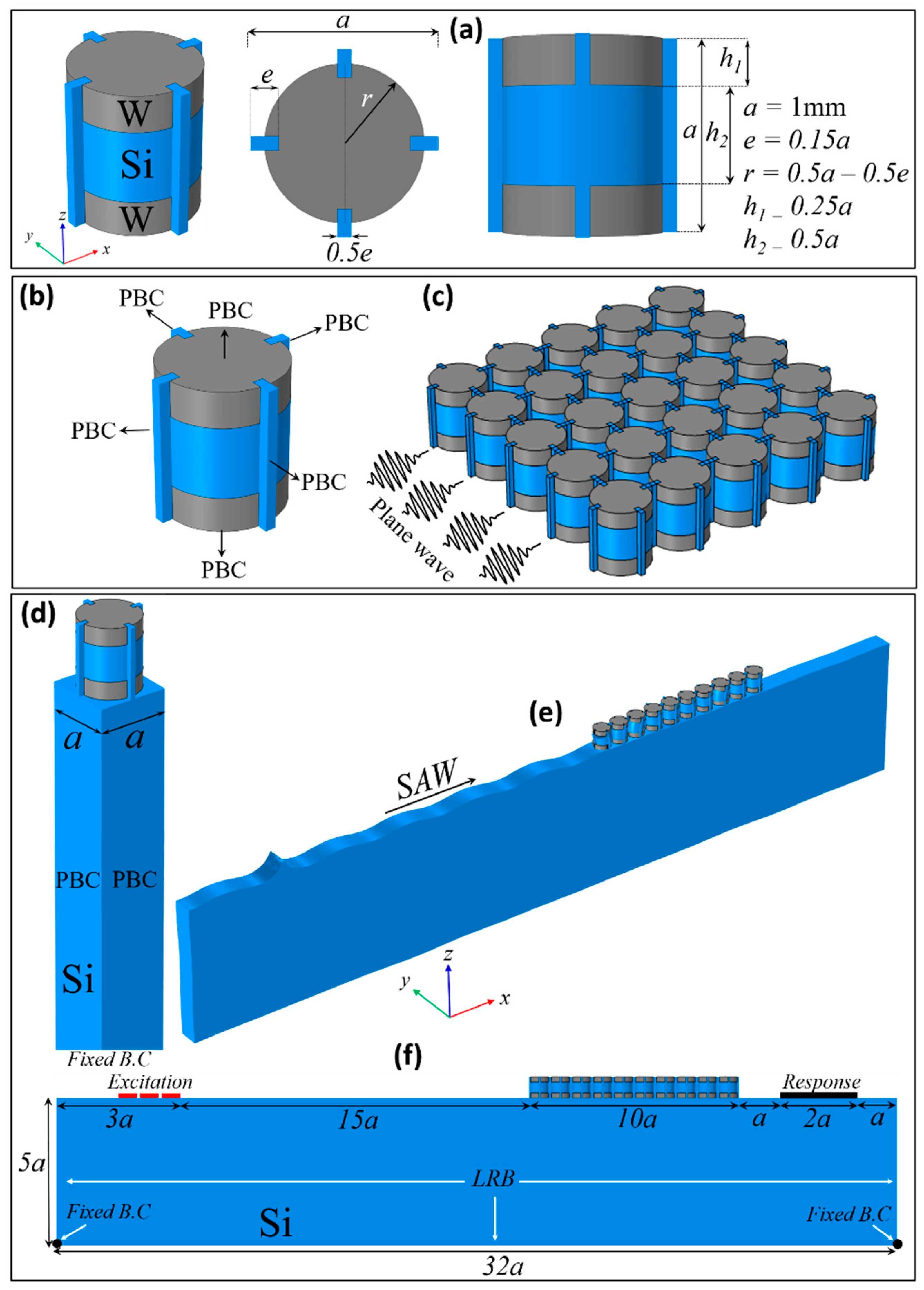
2.1. Unit Cell Structure

The schematic diagram of a PnC unit cell structure is shown in Figure 1a. The geometric parameters are indicated at the inset of the figure, and all other geometric parameters are listed with reference to the lattice constant a = 1 mm. The PnC structure consisted of silicon (Si) and tungsten (W) pillars, where the Si pillar was sandwiched between two W pillars. For simplicity, both materials were assumed to be linear, elastic, and homogenous, and the material properties are listed in Table 1. The study was solely based on numerical computation by using the commercial finite element code COMSOL Multiphysics 5.4®. The PnC structure was designed in such a fashion that made it periodic in all three directions.
We studied both plane wave and SAW propagation and their interaction with the periodic array of PnC structure proposed. For a plane-wave dispersion study, the Floquet–Bloch periodicity condition (PBC) was applied in the x-y-z directions as shown in Figure 1b. The supercell model constructed for the plane wave transmission curve/frequency response study is shown in Figure 1c. For such a periodic array, usually, the harmonic excitation is applied at the left end of the supercell model, and displacement fields are recorded at the opposite end. The displacement field was plotted with swept frequency range of intertest to obtain the wave transmission curve. The transmission ratio was determined by taking the natural log of the ratio of output displacement fields (right end) to input displacement fields (left end) [21,30]. The wave transmission study provides useful information about wave propagation and attenuation at different passband and BG frequencies.
For SAW studies, the schematic diagram of a unit cell structure is shown in Figure 1d, where the Floquet–Bloch periodicity condition was applied on the vertical edges of the semi-infinite half-space in order to obtain the SAW band structure. In Figure 1e–f, the finite length model demonstrating the SAW propagation on the surface of half-space is presented. The harmonic excitation force was applied at the left end as shown in Figure 1f marked as “Excitation”, and the out-of-plane displacement field was captured at the output probe, marked as “response” in Figure 1f. The transmission curve is presented for the frequency range of interest. Besides, for the finite length model, all the geometric parameters are presented with reference to lattice constant a. To ensure SAW propagation and to avoid wave back-reflection at the bottom and side boundaries of the finite length model, the COMSOL built-in low reflection boundary (LRB) condition was applied at both ends and bottom of the finite length model [21]. The LRB condition was found effective in facilitating surface wave propagation at the surface of semi-infinite half-space where other incident bulk waves are made spurious at the ends and bottom of the substrate. This ensures the propagation of surface waves at the surface with a decaying energy field deep into the substrate. Although previous studies adopted the perfectly matched layer boundary condition, LRB has been reported to be more effective in terms of performance and computational efforts [21]. Further, the bottom edges of the finite length model were fixed, and as explained above, the harmonic excitation was applied on the left side at a distance 15a before the PnC supercell. The displacement response was extracted from the output edge placed at a distance a from the PnC supercell. The distance between the PnC array and point of excitation was kept far enough to ensure the SAW propagation and interaction with PnC structures.

2.2. Theory and Mathematical Framework

Although substantial theoretical research works exist in the literature, this section intends to briefly explain the theoretical and mathematical framework for a periodic structure subjected to plane waves and SAW. For more details, one can refer to references [20,21]. The governing Navier equation of motion and the constitutive relation for a heterogeneous medium with isotropic material properties are [68]
ρ 2 u ( r ) t 2 = div σ ; σ = C : u ( r )
where ρ , u ( r ) , t are mass density, position-dependent displacement vector, and time, respectively. Here r = ( x , y , z ) is the position vector, σ is the second-order stress tensor, is vector differential operator and, assuming zero boundary force, C = ( C i j k l ) is fourth-order elasticity tensor that satisfies the generalized Hooke’s law C i j k l = λ δ i j δ k l + μ ( δ i k δ j l + δ i l δ j k ) where i , j , k = 1 , 2 , 3 and { δ i j = 1 , i = j δ i j = 0 , i j } , in which μ and λ are the Lame coefficients. For wave propagation in an elastic medium, the Navier equation for the in-plane wave has a displacement component u = ( u x , u y ) , and for out-of-plane, it is u = u z . Assuming time-harmonic dependence in the form of e i ω t , where ω is the angular frequency, Equation (1) can be simplified as
div σ + ρ ω 2 u = 0 ; σ = μ u
In this study, the spacing between PnCs was assumed as a. To study the characteristics of wave propagation in an infinite domain, the Floquet–Bloch periodicity condition [69] was applied. The theory received extensive amount of attention with increasing research growth in photonic crystals, PnCs, and acoustic metamaterials. Initially, the theory was developed to solve differential equations in particle physics. Today, it is widely adopted for solving differential equations in other branches of physics and mathematics. According to this theory, the solution of Equation (1) can be expressed as
u ( r , t ) = u k ( r ) e i ( k . r ω t )
where u k ( r ) is the displacement modulation function [20]. Since the PnC unit cell is periodic in the x-y-z directions, the wavenumber k is swept across the Γ X M Γ R X M R coordinate of IBZ [65]. Further details about the Brillouin reciprocal lattices and Brillouin zone can be found in Muhammad et al. [20]. In Equation (3), the periodicity of the modulation constant u k ( r ) is the same as that of the lattice constant a of the primitive cell. Thus, one can consider,
u k ( r + a ) = u k ( r )
Substitution of Equation (4) into Equation (3) yields
u ( r + a , t ) = u k ( r + a ) e i ( k ( r + a ) ω t ) = e i k a u k ( r ) e i ( k . r ω t ) = e i k . a u ( r , t )
which are the periodic boundary conditions applied in x-y-z directions. Further simplification leads to the eigenvalue problem of the following form [20]:
( Φ ( k ) ω 2 M ) . U = 0
where Φ is the stiffness matrix that is a function of the wavevector k , and M is the mass matrix. The wave dispersion plot/band structure is a graphical representation of the wavenumber swept at the boundary of the irreducible Brillouin zone versus eigenfrequencies of the PnC structure [20]. Physically, it shows the response of eigenmodes or the natural frequency of the structure for varying wave speed and wavenumber.
The analysis above is related to the plane wave propagation. SAW is another type of wave that contains the maximum amount of wave energy at the surface and with exponentially decaying energy fields down into the substrate/host media. In order to achieve the SAW band structure, the bottom of the semi-infinite half-space was fixed (see Figure 1d). The SAW eigenmodes were separated from the bulk and leaky surface modes by the sound cone technique [20]. The sound cone technique distributes the band structure into radiative and non-radiative regions. All modes that contained the maximum amount of wave energy concentrate at the PnC structure were placed outside the sound cone in the non-radiative zone. In contrast, other bulk and leaky surface modes with wave energy concentrated deep into the substrate were placed inside the sound cone. Thus, in this way, the SAW wave modes were separated from other bulk wave modes. Here, in Figure 2 and in Figure 5 and Figure 6 below the sound cone radiative region and boundary of the sound cone/sound line are highlighted by light green and red lines, respectively.

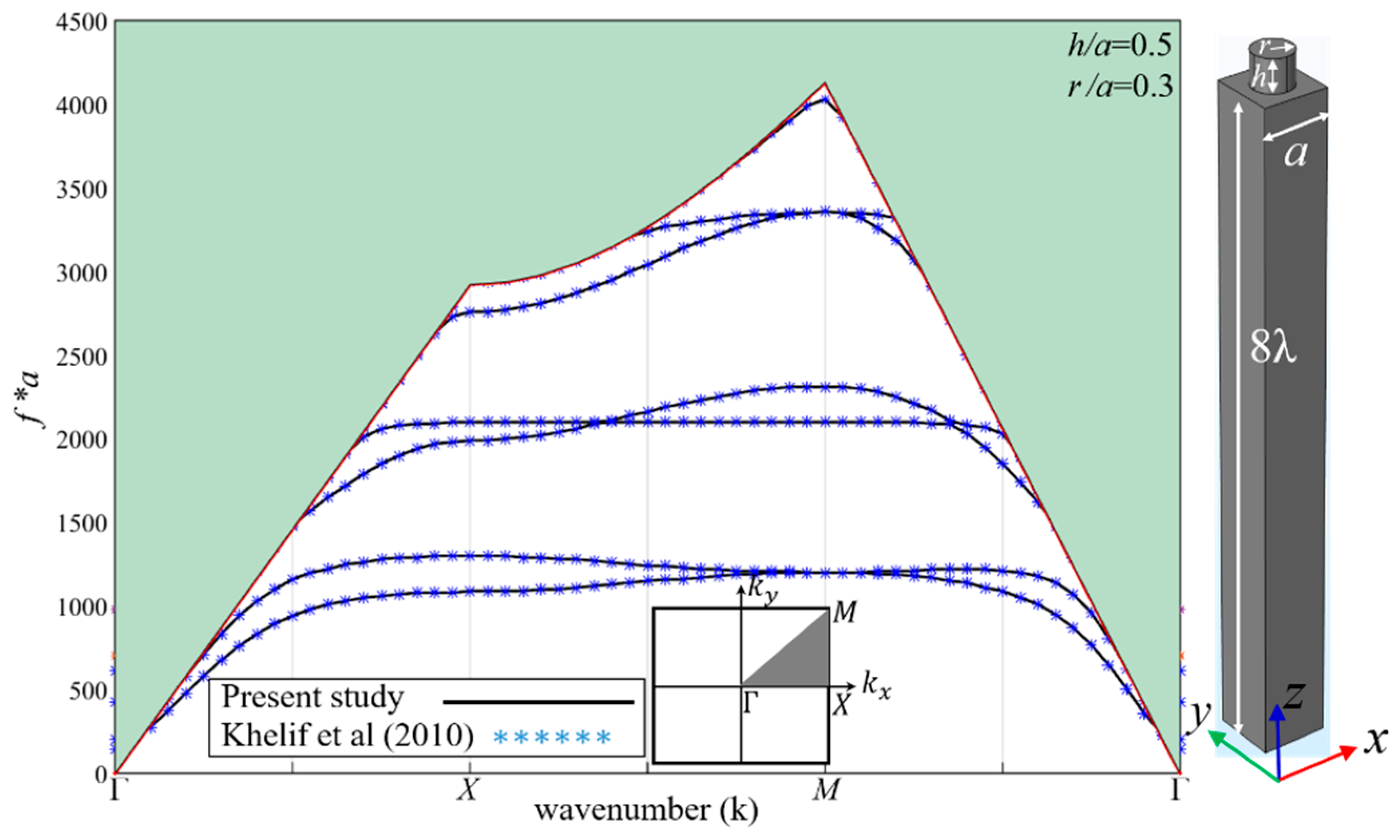
2.3. Model Validation

To substantiate the numerical analysis in this study, we compared the numerical solutions with the theoretical work of Khelif et al. [40], who studied SAW propagation for a simple pillar placed on the surface of semi-infinite half-space. As shown in Figure 2, an excellent agreement is achieved between the adopted computation approach and reported results. Thus, the accuracy of the present computational technique is validated.

3. Results and Discussion

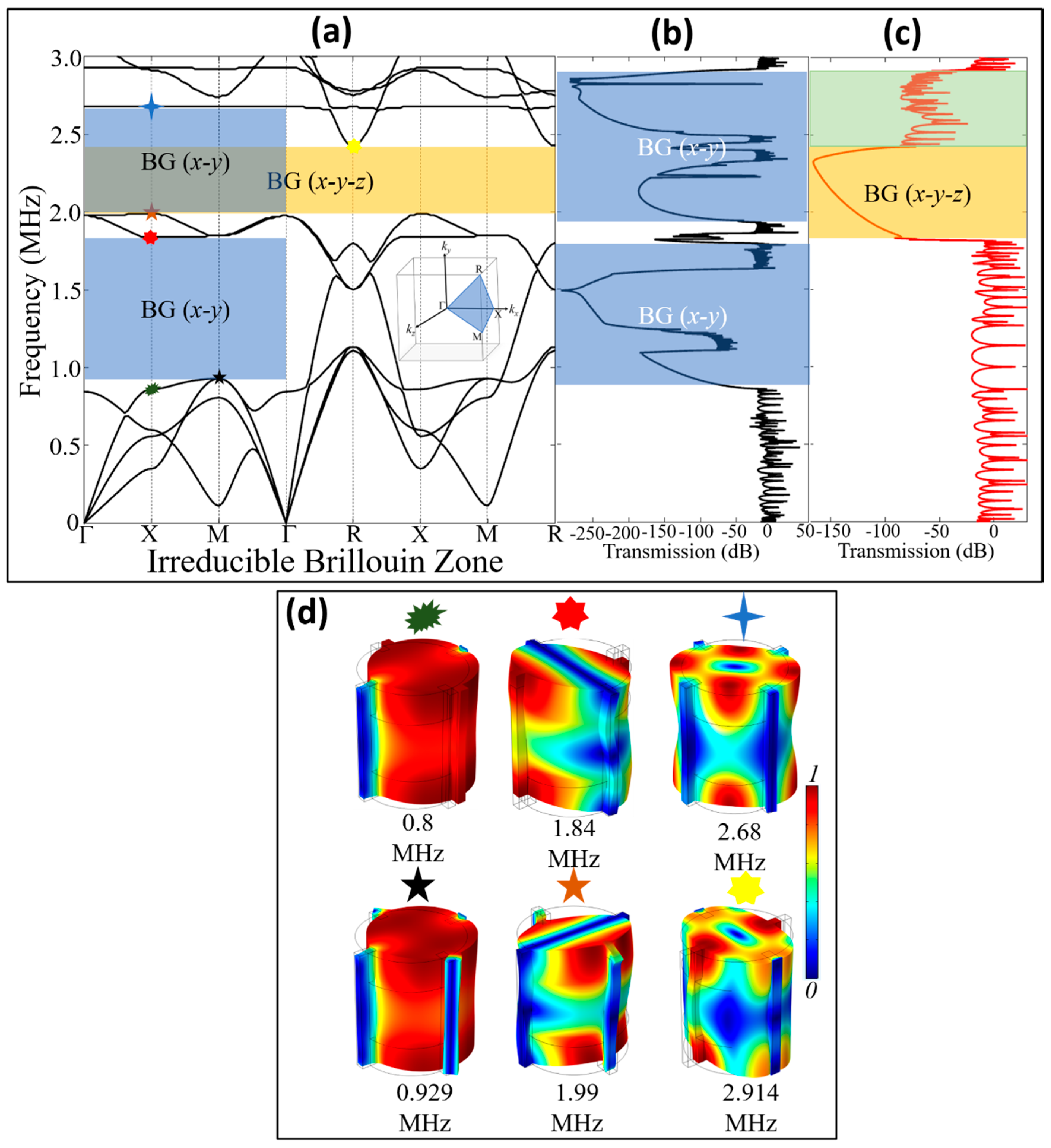
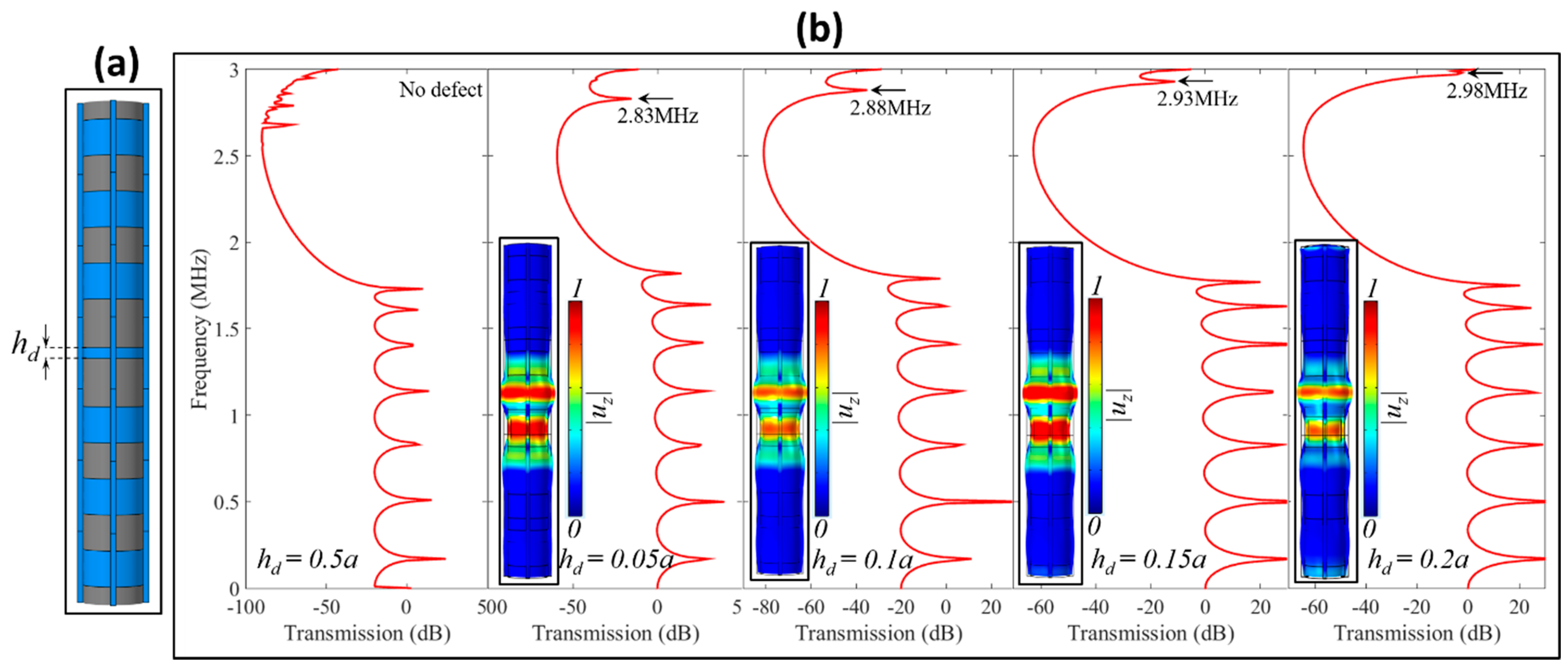
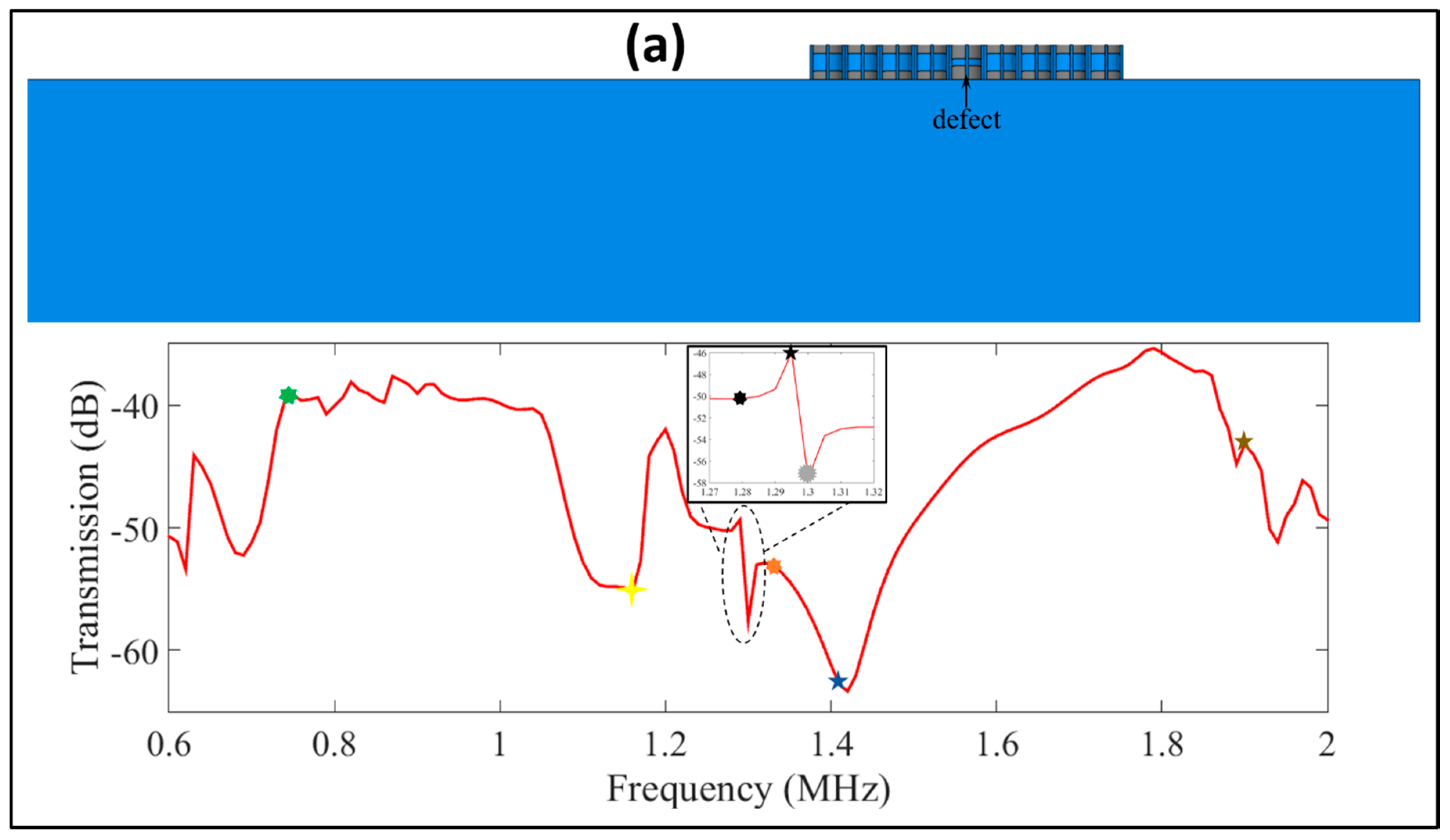
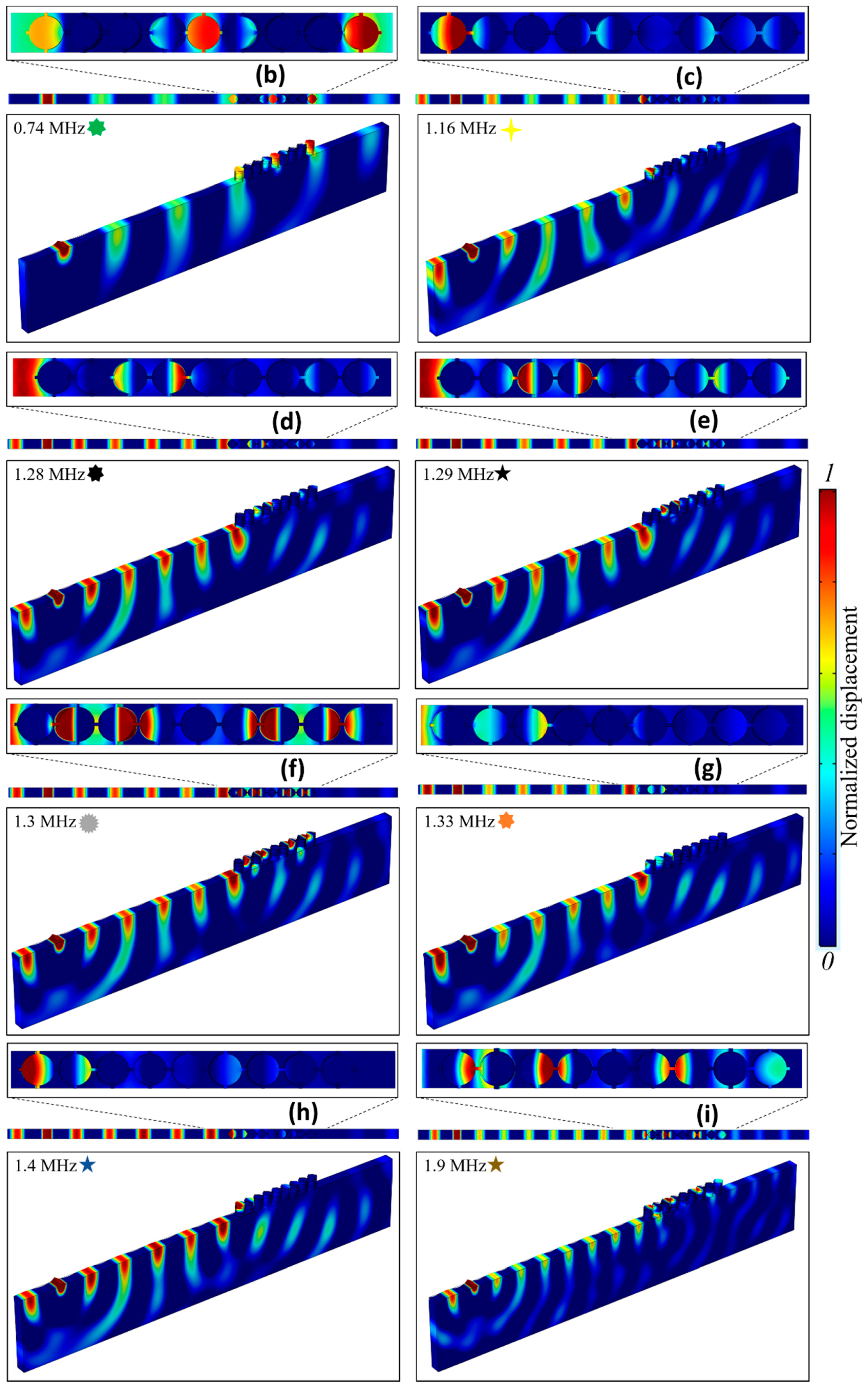
3.1. Plane Wave Propagation and Defect Analysis

The unit cell structure and theoretical concepts are explained in the prior sections. This section deals with the study of plane wave propagation and defect analysis for a finite supercell structure. In Figure 3a, the band structure with BGs in the x-y directions, i.e., Γ X M Γ ; z-direction, i.e., R X M R ; and x-y-z directions are presented. The BG was generated due to the coupling of plane wave with local resonances of the PnC unit cell structure. At the BG opening edge, the vibration is concentrated in the complete unit cell structure as shown in Figure 3d. Thus, it enhances the effective mass density and moment of inertia and as a result the eigenfrequency lies at a relatively low frequency. At the closing bounding edge, the structure is in flexural vibration with distributed displacement fields/vibrational energy at a few parts of the structure as a result the eigenfrequency lies at a relatively higher frequency region. A similar trait can be seen across the boundary of IBZ for other points at Γ X M Γ (first BG) and Γ X M Γ R X M R (second BG) coordinates. These differences caused by the local and global resonance of structure result in the opening and closing of the BG [65].
To envisage the wave attenuation in the BG frequency, a finite array of unit cell structures (supercell) was constructed (see Figure 1c). Figure 3b,c shows the frequency response spectrum for a finite number of unit cells periodic in x-y and z directions, respectively. The vibration modes involved in the opening and closing of the BG are shown in Figure 3d. For the wave transmission study in Figure 3b,c, the total displacement field in x-y-z directions was captured in the frequency response spectrum plot. For the same reason, one can observe that, in Figure 3c, half of the BG ranging from 1.84 MHz to 2.68 MHz is very clear in term of plane wave attenuation; however, the response peaks above 2.68 MHz to 2.9 MHz is observed. Although response peaks exist and the curve of BG is not smooth, the displacement field distribution in the supercell model shows it is the BG frequency region where wave propagation is prohibited in supercell structure. A possible reason for these transmission peaks is as follows: We captured the total displacement field in all three directions for the transmission curve, and the in-plane and out-of-plane eigenmodes between 2.68 MHz and 2.9 MHz cause disturbances due to out-of-plane and in-plane wave modes polarization (see mode shape in Figure 3d (yellow star)). Although its effect is not very strong, it results in minor transmission peaks inside the second BG. Later, when a similar frequency response for only out-of-plane mode was captured, such transmission peaks disappeared, as shown in Figure 4. Thus, it is evident that such spurious transmission peaks inside the second BG in Figure 3c are due to the complex polarization of wave modes.
Based on the wave transmission curved shown in Figure 3c, we constructed a supercell structure with defect height h d as shown in Figure 4a. The supercell structure consisted of seven unit cells with a defect state in-between. A harmonic excitation was applied to the bottom most layer, and out-of-plane displacement field/ z-direction | u z | was recorded on the top most layer. Figure 4b shows the frequency response spectrum for normal and defective states. The h d was selected as 0.05a, 0.1a, 0.15a, and 0.2a. Beyond 0.2a, the defect state frequency exceeded the BG range of interest, and thus the analysis stopped beyond this point. The defect in the form of transmission peak and displacement field distribution is shown at the inset of each figure. For all the cases considered, at the corresponding defect frequency, energy is concentrated/localized inside the defect, and no vibration is observed in other unit cell structures. Such tailorable defect states can be of prime importance for energy harvesting and sensing applications.

3.2. SAW Propagation and Defect Analysis

The procedure involved for SAW generation and wave dispersion study was explained in Section 2. The SAW band structure for the proposed PnC unit cell is shown in Figure 5a, and the geometric parameters are highlighted in Figure 1. Identical to the plane wave band structure shown in Figure 3a, BG is initiated at around 0.8 MHz. The BG is induced due to the coupling of SAWs with the local resonance of periodic PnC structures. The detailed study for SAW BG generation was presented by the authors in which the opening and closing of BG were envisaged both numerically and experimentally [40,58]. Details on the phenomena of BG generation is outside the scope of this study. To envisage the SAW attenuation inside the BG frequency range, a finite length model, see Figure 1e–f, was constructed, and a frequency response study was performed. A total of 10 PnC unit cells for the SAW frequency response study were considered, and the transmission curve is shown in Figure 5b. From the transmission curve, one can observe SAW attenuation inside the BG frequency range. Further, the flexural, longitudinal, torsional, and other mixed vibration modes of PnC structure subjected to SAW are shown in Figure 5c. One can observe the concentration of wave energy at the PnC surface and decaying energy field deep into the Si substrate.
Next, the height of Si, i.e., h 2 , is changed (see Figure 1a), and the SAW band structure is presented. In Figure 6a–e, the band structures for h 2 = 0.2 a , 0.4 a , 0.5 a , 0.6 a , 0.8 a are shown, respectively. The variation in the reported SAW vibration modes (see Figure 5c) can be seen. An increase in the height of tungsten (W) pillars, i.e., h 1 , increases the PnC effective mass. Thus, eigenmodes shift to a lower frequency region. Similarly, one can observe for a smaller h 1 the same eigenmodes lie at relatively higher frequencies. If one adjusts h 2 such that a passband exists inside BG of the parent unit cell structure, SAW energy can be trapped/localized in that particular defective PnC unit cell structure [8].
The defect analysis for the two cases is presented here. In the first case, the height of the parent Si pillar was h 2 = 0.5 a , and the defect size was h 2 d = 0.8 a . In total, nine unit cell structures were considered, with eight parent cells and one defective unit cell structure, in which h 2 d = 0.8 a , as shown in Figure 7a. Due to the induced defects, the transmission curve shows some unusual transmission peaks that are not observed in normal cases without defect. The transmission curve is shown in Figure 7b, with different frequencies highlighted using multiple symbols where wave attenuation, trapping/localization, transmission, and isolation at the defect state is observed. As shown in Figure 7b, at 1.05 MHz, the trapping of SAW inside the defect can be observed.
Similarly, Figure 7c–e shows the displacement field for 1.29 MHz, 1.295 MHz, and 1.3 MHz. For 1.29 MHz and 1.3 MHz, there is no vibration observed inside the defect. However, in the other parent unit cells, SAW propagation is observed. In contrast, for 1.295 MHz, there is no vibration captured in both defect and parent structures. Identical characteristics are observed in Figure 7f–h where for 0.749 MHz, the defect is not in vibration, while for 0.765 MHz, almost no SAW propagation is noticed in the array of periodic unit cells. The SAW trapping/localization is observed at 0.782 MHz.
In the second case, nine supercells including eight parent cells and one defected pillar were considered. The defect height was h 2 d = 0.2 a . Figure 8a shows the finite length model and frequency response spectrum/transmission curve. Likewise, the displacement field for particular frequencies demonstrating the wave trapping and isolation inside the defect are highlighted by different symbols, as shown at the inset of the transmission curve. For marked frequencies, the displacement field plots are shown in Figure 8b–i, where the wave energy localization/trapping, isolation, and transmission of SAW are demonstrated.

4. Conclusions

In summary, the present study proposes a novel phononic crystal design that consists of multilayered composite silicon and tungsten pillars/ridges supported/confined by side silicon bars/wings. The introduction of side silicon wings and staked silicon-tungsten ridge structure can be made periodic in all three-directions by applying the Floquet–Bloch periodicity condition on all vertical edges and top-bottom surfaces. The plane wave and surface acoustic wave propagation, wave attenuation, wave trapping/localization, and wave transmission properties were investigated in detail. By wave dispersion and frequency response studies, the two-dimensional and three-dimensional bandgaps were highlighted and analyzed. The wave attenuation in the bandgap frequency was demonstrated. A defect was induced in a supercell array, and plane wave propagation and energy localization/trapping were studied for different frequencies. At the defect state, the in-plane wave energy was confined/trapped, and there was no wave propagation observed in the neighboring unit cells. The trapped/localized frequency can be made tailorable by varying the defect size. Likewise, by considering two defect cases, SAW propagation, localization/trapping, transmission, and attenuation in the bandgap frequency were also demonstrated. Due to the presence of a defect in a supercell array, the SAW transmission curve showed distinct transmission peaks. By displacement field plots, the governing SAW characteristics at particular frequencies were also studied. The three-dimensional bandgap property, plane wave, and SAW manipulation capability, and simple structure configuration make the proposed phononic crystal a good choice for energy harvesting, waveguiding, sensing, wave localization/trapping, filtering, and wave isolation. The proposed phononic crystal design may find potential applications in electronic and MEMS devices for sensing and energy harvesting purposes. The future study will explore the fabrication technique for the proposed phononic structures and experiment tests on manufactured prototypes.

Author Contributions

Conceptualization, Methodology, Software, Formal Analysis, Investigation, Data Curation, Writing—original draft, Visualization, Validation: M.; Funding acquisition, Writing—review and editing, Project administration, Resources, Supervision: C.W.L.; Writing—review and editing, Project administration, Resources: A.Y.T.L. All authors have read and agreed to the published version of the manuscript.

Funding

The work described in this paper was supported by General Research Grants from the Research Grants Council of the Hong Kong Special Administrative Region (Project No. CityU 11216318).

Institutional Review Board Statement

Not applicable.

Informed Consent Statement

Not applicable.

Data Availability Statement

The data presented in this study are available on request from the corresponding author.

Conflicts of Interest

The authors declare no conflict of interest.

References

  1. Pennec, Y.; Djafari-Rouhani, B.; Vasseur, J.O.; Khelif, A.; Deymier, P.A. Tunable filtering and demultiplexing in phononic crystals with hollow cylinders. Phys. Rev. E Stat. Nonlin. Soft Matter Phys. 2004, 69, 046608. [Google Scholar] [CrossRef] [PubMed] [Green Version]
  2. Qiu, C.Y.; Liu, Z.Y.; Mei, J.; Shi, J. Mode-selecting acoustic filter by using resonant tunneling of two-dimensional double phononic crystals. Appl. Phys. Lett. 2005, 87, 104101. [Google Scholar] [CrossRef]
  3. Kumar, S.; Lee, H.P. The present and future role of acoustic metamaterials for architectural and urban noise mitigations. In Proceedings of Acoustics; Multidisciplinary Digital Publishing Institute: Basel, Switzerland, 2019; pp. 590–607. [Google Scholar]
  4. Ang, L.Y.L.; Koh, Y.K.; Lee, H.P. Plate-type acoustic metamaterials: Experimental evaluation of a modular large-scale design for low-frequency noise control. In Proceedings of Acoustics; Multidisciplinary Digital Publishing Institute: Basel, Switzerland, 2019; pp. 354–368. [Google Scholar]
  5. Zhang, X.; Liu, Z. Superlenses to overcome the diffraction limit. Nat. Mater. 2008, 7, 435–441. [Google Scholar] [CrossRef] [PubMed]
  6. De Ponti, J.M.; Colombi, A.; Ardito, R.; Braghin, F.; Corigliano, A.; Craster, R.V. Graded metasurface for enhanced sensing and energy harvesting. arXiv 2019, arXiv:1907.09297. [Google Scholar]
  7. Jin, Y.B.; Fernez, N.; Pennec, Y.; Bonello, B.; Moiseyenko, R.P.; Hemon, S.; Pan, Y.D.; Djafari-Rouhani, B. Tunable waveguide and cavity in a phononic crystal plate by controlling whispering-gallery modes in hollow pillars. Phys. Rev. B 2016, 93, 054109. [Google Scholar] [CrossRef] [Green Version]
  8. Lim, C.W.; Reddy, J.N.; Carrera, E.; Xu, X.; Zhou, Z. Surface elastic waves whispering gallery modes based subwavelength tunable waveguide and cavity modes of the phononic crystals. Mech. Adv. Mater. Struct. 2020, 27, 1053–1064. [Google Scholar] [CrossRef]
  9. Craster, R.V.; Guenneau, S. Acoustic Metamaterials: Negative Refraction, Imaging, Lensing and Cloaking; Springer Science & Business Media: Berlin, Germany, 2012; Volume 166. [Google Scholar]
  10. Cummer, S.A.; Schurig, D. One path to acoustic cloaking. New J. Phys. 2007, 9, 45. [Google Scholar] [CrossRef]
  11. Ning, L.; Wang, Y.-Z.; Wang, Y.-S. Active control cloak of the elastic wave metamaterial. Int. J. Solids Struct. 2020, 202, 126–135. [Google Scholar] [CrossRef]
  12. Lim, C.W. Analytical modeling and computation on topological properties of protected interface state of 1-d phononic crystal in elastic media. J. Mech. Mater. Struct. 2020, 15, 15–35. [Google Scholar] [CrossRef]
  13. Zhou, W.; Lim, C.W. Topological edge modeling and localization of protected interface modes in 1D phononic crystals for longitudinal and bending elastic waves. Int. J. Mech. Sci. 2019, 159, 359–372. [Google Scholar] [CrossRef]
  14. Zhou, W.; Su, Y.; Chen, W.; Lim, C.W. Voltage-controlled quantum valley Hall effect in dielectric membrane-type acoustic metamaterials. Int. J. Mech. Sci. 2020, 172, 105368. [Google Scholar] [CrossRef]
  15. Zhou, W.J.; Chen, W.Q.; Lim, C.W. Surface effect on the propagation of flexural waves in periodic nano-beam and the size-dependent topological properties. Compos. Struct. 2019, 216, 427–435. [Google Scholar] [CrossRef]
  16. Zhou, W.J.; Chen, W.Q.; Chen, Z.Y.; Lim, C.W. Actively controllable flexural wave band gaps in beam-type acoustic metamaterials with shunted piezoelectric patches. Eur. J. Mech. Solid 2019, 77, 103807. [Google Scholar] [CrossRef]
  17. Brule, S.; Javelaud, E.H.; Enoch, S.; Guenneau, S. Experiments on seismic metamaterials: Molding surface waves. Phys. Rev. Lett. 2014, 112, 133901. [Google Scholar] [CrossRef] [PubMed] [Green Version]
  18. Lim, C.W. Wide Rayleigh waves bandgap engineered metabarriers for seismic shielding of civil infrastructures. J. Eng. Mech. 2020, in press. [Google Scholar]
  19. Lim, C.W. Elastic waves propagation in thin plate metamaterials and evidence of low frequency pseudo and local resonance bandgaps. Phys. Lett. A 2019, 383, 2789–2796. [Google Scholar] [CrossRef]
  20. Lim, C.W.; Reddy, J.N. Built-up structural steel sections as seismic metamaterials for surface wave attenuation with low frequency wide bandgap in layered soil medium. Eng. Struct. 2019, 188, 440–451. [Google Scholar] [CrossRef]
  21. Wu, T.; Lim, C.W. Forest trees as naturally available seismic metamaterials: Low frequency Rayleigh waves with extremely wide bandgaps. Int. J. Struct. Stab. Dyn. 2020, 2043014. [Google Scholar] [CrossRef]
  22. Zhou, W.J.; Wu, B.; Du, Q.J.; Huang, G.L.; Lu, C.F.; Chen, W.Q. Actively tunable transverse waves in soft membrane-type acoustic metamaterials. J. Appl. Phys. 2018, 123, 165304. [Google Scholar] [CrossRef]
  23. Huang, H.H.; Sun, C.T.; Huang, G.L. On the negative effective mass density in acoustic metamaterials. Int. J. Eng. Sci. 2009, 47, 610–617. [Google Scholar] [CrossRef]
  24. Park, J.; Park, B.; Kim, D.; Park, J. Determination of effective mass density and modulus for resonant metamaterials. J. Acoust. Soc. Am. 2012, 132, 2793–2799. [Google Scholar] [CrossRef] [PubMed] [Green Version]
  25. Ren, X.; Das, R.; Tran, P.; Ngo, T.D.; Xie, Y.M. Auxetic metamaterials and structures: A review. Smart Mater. Struct. 2018, 27, 023001. [Google Scholar] [CrossRef]
  26. Yu, K.; Fang, N.X.; Huang, G.; Wang, Q. Magnetoactive Acoustic Metamaterials. Adv. Mater. 2018, 30, 1706348. [Google Scholar] [CrossRef] [PubMed]
  27. Yu, X.; Zhou, J.; Liang, H.; Jiang, Z.; Wu, L. Mechanical metamaterials associated with stiffness, rigidity and compressibility: A brief review. Prog. Mater. Sci. 2018, 94, 114–173. [Google Scholar] [CrossRef]
  28. An, N.; Domel, A.G.; Zhou, J.; Rafsanjani, A.; Bertoldi, K. Programmable Hierarchical Kirigami. Adv. Funct. Mater. 2020, 30, 1906711. [Google Scholar] [CrossRef]
  29. Barnhart, M.V.; Xu, X.C.; Chen, Y.Y.; Zhang, S.; Song, J.Z.; Huang, G.L. Experimental demonstration of a dissipative multi-resonator metamaterial for broadband elastic wave attenuation. J. Sound Vib. 2019, 438, 1–12. [Google Scholar] [CrossRef]
  30. Lim, C.W. Dissipative multiresonant pillared and trampoline metamaterials with amplified local resonance bandgaps and broadband vibration attenuation. J. Vib. Acoust. 2020, 142, 061012. [Google Scholar] [CrossRef]
  31. Lim, C.W.; Li, J.T.H.; Zhao, Z. Lightweight architected lattice phononic crystals with broadband and multiband vibration mitigation characteristics. Extrem. Mech. Lett. 2020, 41, 100994. [Google Scholar] [CrossRef]
  32. Ang, L.Y.L.; Koh, Y.K.; Lee, H.P. Acoustic Metamaterials: A Potential for Cabin Noise Control in Automobiles and Armored Vehicles. Int. J. Appl. Mech. 2016, 8, 1650072. [Google Scholar] [CrossRef] [Green Version]
  33. Vyas, N.S.; Lim, C.W. A Novel Application of Multi-Resonant Dissipative Elastic Metahousing For Bearings. SAGE J. Vib. Control 2020. under review. [Google Scholar]
  34. Liu, Y.; Du, J.; Cheng, L. Bandgap formation under temperature-induced quasi-periodicity in an acoustic duct with flexible walls. J. Sound Vib. 2020, 486, 115615. [Google Scholar] [CrossRef]
  35. Huang, Z.; Zhao, S.; Su, M.; Yang, Q.; Li, Z.; Cai, Z.; Zhao, H.; Hu, X.; Zhou, H.; Li, F.; et al. Bioinspired Patterned Bubbles for Broad and Low-Frequency Acoustic Blocking. ACS Appl. Mater. Interfaces 2020, 12, 1757–1764. [Google Scholar] [CrossRef] [PubMed]
  36. Allam, A.; Sabra, K.; Erturk, A. 3D-Printed Gradient-Index Phononic Crystal Lens for Underwater Acoustic Wave Focusing. Phys. Rev. Appl. 2020, 13, 064064. [Google Scholar] [CrossRef]
  37. Lim, C.W. From photonic crystals to seismic metamaterials: A review via phononic crystals and acoustic metamaterials. Appl. Mech. Rev. 2020. under review. [Google Scholar]
  38. Wang, Y.-F.; Wang, Y.-Z.; Wu, B.; Chen, W.; Wang, Y.-S. Tunable and active phononic crystals and metamaterials. Appl. Mech. Rev. 2020, 72, 040801. [Google Scholar] [CrossRef]
  39. Meseguer, F.; Holgado, M.; Caballero, D.; Benaches, N.; Sanchez-Dehesa, J.; Lopez, C.; Llinares, J. Rayleigh-wave attenuation by a semi-infinite two-dimensional elastic-band-gap crystal. Phys. Rev. B 1999, 59, 12169–12172. [Google Scholar] [CrossRef] [Green Version]
  40. Khelif, A.; Achaoui, Y.; Benchabane, S.; Laude, V.; Aoubiza, B. Locally resonant surface acoustic wave band gaps in a two-dimensional phononic crystal of pillars on a surface. Phys. Rev. B 2010, 81, 1–7. [Google Scholar] [CrossRef] [Green Version]
  41. Williams, E.G.; Roux, P.; Rupin, M.; Kuperman, W.A. Theory of multiresonant metamaterials forA0Lamb waves. Phys. Rev. B 2015, 91, 104307. [Google Scholar] [CrossRef] [Green Version]
  42. Oudich, M.; Djafari-Rouhani, B.; Bonello, B.; Pennec, Y.; Sarry, F. Phononic Crystal Made of Multilayered Ridges on a Substrate for Rayleigh Waves Manipulation. Crystals 2017, 7, 372. [Google Scholar] [CrossRef] [Green Version]
  43. Oudich, M.; Djafari-Rouhani, B.; Bonello, B.; Pennec, Y.; Hemaidia, S.; Sarry, F.; Beyssen, D. Rayleigh Waves in Phononic Crystal Made of Multilayered Pillars: Confined Modes, Fano Resonances, and Acoustically Induced Transparency. Phys. Rev. Appl. 2018, 9, 034013. [Google Scholar] [CrossRef]
  44. Hussein, M.I.; Leamy, M.J.; Ruzzene, M. Dynamics of Phononic Materials and Structures: Historical Origins, Recent Progress, and Future Outlook. Appl. Mech. Rev. 2014, 66, 040802. [Google Scholar] [CrossRef]
  45. Zhou, X.; Assouar, M.B.; Oudich, M. Acoustic superfocusing by solid phononic crystals. Appl. Phys. Lett. 2014, 105, 233506. [Google Scholar] [CrossRef] [Green Version]
  46. Siddiqi, M.; Lee, J. Wide acoustic bandgap solid disk-shaped phononic crystal anchoring boundaries for enhancing quality factor in AlN-on-Si MEMS resonators. Micromachines 2018, 9, 413. [Google Scholar] [CrossRef] [PubMed] [Green Version]
  47. Zhu, J.; Chen, Y.; Zhu, X.; Garcia-Vidal, F.J.; Yin, X.; Zhang, W.; Zhang, X. Acoustic rainbow trapping. Sci. Rep. 2013, 3, 1728. [Google Scholar] [CrossRef] [Green Version]
  48. Bilal, O.R.; Hussein, M.I. Trampoline metamaterial: Local resonance enhancement by springboards. Appl. Phys. Lett. 2013, 103, 111901. [Google Scholar] [CrossRef] [Green Version]
  49. Achaoui, Y.; Laude, V.; Benchabane, S.; Khelif, A. Local resonances in phononic crystals and in random arrangements of pillars on a surface. J. Appl. Phys. 2013, 114, 104503. [Google Scholar] [CrossRef]
  50. Pennec, Y.; Djafari Rouhani, B.; Larabi, H.; Akjouj, A.; Gillet, J.N.; Vasseur, J.O.; Thabet, G. Phonon transport and waveguiding in a phononic crystal made up of cylindrical dots on a thin homogeneous plate. Phys. Rev. B 2009, 80, 144302. [Google Scholar] [CrossRef]
  51. Pennec, Y.; Djafari-Rouhani, B.; Larabi, H.; Vasseur, J.O.; Hladky-Hennion, A.C. Low-frequency gaps in a phononic crystal constituted of cylindrical dots deposited on a thin homogeneous plate. Phys. Rev. B 2008, 78, 104105. [Google Scholar] [CrossRef]
  52. Wu, T.-C.; Wu, T.-T.; Hsu, J.-C. Waveguiding and frequency selection of Lamb waves in a plate with a periodic stubbed surface. Phys. Rev. B 2009, 79, 104306. [Google Scholar] [CrossRef]
  53. Wu, T.T.; Huang, Z.G.; Tsai, T.C.; Wu, T.C. Evidence of complete band gap and resonances in a plate with periodic stubbed surface. Appl. Phys. Lett. 2008, 93, 98–101. [Google Scholar] [CrossRef]
  54. Oudich, M.; Senesi, M.; Assouar, M.B.; Ruzenne, M.; Sun, J.-H.; Vincent, B.; Hou, Z.; Wu, T.-T. Experimental evidence of locally resonant sonic band gap in two-dimensional phononic stubbed plates. Phys. Rev. B 2011, 84, 165136. [Google Scholar] [CrossRef]
  55. Oudich, M.; Zhou, X.; Assouar, M.B. General analytical approach for sound transmission loss analysis through a thick metamaterial plate. J. Appl. Phys. 2014, 116, 193509. [Google Scholar] [CrossRef] [Green Version]
  56. Jin, Y.; Pennec, Y.; Pan, Y.; Djafari-Rouhani, B. Phononic crystal plate with hollow pillars connected by thin bars. J. Phys. D Appl. Phys. 2016, 50, 035301. [Google Scholar] [CrossRef]
  57. Jin, Y.; Pennec, Y.; Pan, Y.; Djafari-Rouhani, B. Phononic Crystal Plate with Hollow Pillars Actively Controlled by Fluid Filling. Crystals 2016, 6, 64. [Google Scholar] [CrossRef] [Green Version]
  58. Achaoui, Y.; Khelif, A.; Benchabane, S.; Robert, L.; Laude, V. Experimental observation of locally-resonant and Bragg band gaps for surface guided waves in a phononic crystal of pillars. Phys. Rev. B 2011, 83, 1–5. [Google Scholar] [CrossRef] [Green Version]
  59. Robillard, J.F.; Devos, A.; Roch-Jeune, I. Time-resolved vibrations of two-dimensional hypersonic phononic crystals. Phys. Rev. B 2007, 76, 092301. [Google Scholar] [CrossRef]
  60. Giannetti, C.; Revaz, B.; Banfi, F.; Montagnese, M.; Ferrini, G.; Cilento, F.; Maccalli, S.; Vavassori, P.; Oliviero, G.; Bontempi, E.; et al. Thermomechanical behavior of surface acoustic waves in ordered arrays of nanodisks studied by near-infrared pump-probe diffraction experiments. Phys. Rev. B 2007, 76, 125413. [Google Scholar] [CrossRef] [Green Version]
  61. Yudistira, D.; Boes, A.; Graczykowski, B.; Alzina, F.; Yeo, L.Y.; Sotomayor Torres, C.M.; Mitchell, A. Nanoscale pillar hypersonic surface phononic crystals. Phys. Rev. B 2016, 94, 094304. [Google Scholar] [CrossRef] [Green Version]
  62. Colombi, A.; Roux, P.; Guenneau, S.; Gueguen, P.; Craster, R.V. Forests as a natural seismic metamaterial: Rayleigh wave bandgaps induced by local resonances. Sci. Rep. 2016, 6, 19238. [Google Scholar] [CrossRef] [Green Version]
  63. De Ponti, J.M.; Colombi, A.; Ardito, R.; Braghin, F.; Corigliano, A.; Craster, R.V. Graded elastic metasurface for enhanced energy harvesting. New J. Phys. 2020, 22, 013013. [Google Scholar] [CrossRef]
  64. Chaplain, G.J.; De Ponti, J.M.; Colombi, A.; Fuentes-Dominguez, R.; Dryburg, P.; Pieris, D.; Smith, R.J.; Clare, A.; Clark, M.; Craster, R.V. Tailored elastic surface to body wave Umklapp conversion. Nat. Commun. 2020, 11, 3267. [Google Scholar] [CrossRef] [PubMed]
  65. D’Alessandro, L.; Belloni, E.; Ardito, R.; Braghin, F.; Corigliano, A. Mechanical low-frequency filter via modes separation in 3D periodic structures. Appl. Phys. Lett. 2017, 111, 231902. [Google Scholar] [CrossRef]
  66. Lim, C.W. Ultrawide 3D phononic bandgap metastructures as broadband low frequency filter. Sci. Rep. 2020. submitted. [Google Scholar]
  67. Lim, C.W. Ultrawide bandgap by 3D monolithic mechanical metastructure for vibration and noise control. Arch. Civ. Mech. Eng. 2020. submitted. [Google Scholar]
  68. Maurel, A.; Marigo, J.-J.; Pham, K.; Guenneau, S. Conversion of Love waves in a forest of trees. Phys. Rev. B 2018, 98, 134311. [Google Scholar] [CrossRef] [Green Version]
  69. Hofstadter, D.R. Energy-Levels and Wave-Functions of Bloch Electrons in Rational and Irrational Magnetic-Fields. Phys. Rev. B 1976, 14, 2239–2249. [Google Scholar] [CrossRef]
Figure 1. The phononic crystal (PnC) unit cell structure and finite-length model: (a) 3D, top and plan view; (b) unit cell structure with perfect boundary condition (PBC) applied along all vertical edges and top-bottom; (c) supercell model used for plane wave transmission curve study; (d) unit cell structure utilized for surface acoustic wave (SAW) band structure study; (e) finite-length model with SAW propagation at the surface of semi-infinite half-space can be observed; and (f) supercell model adopted for SAW transmission, attenuation and defect analysis.
Acoustics 03 00004 g001
Figure 2. Model validation.
Acoustics 03 00004 g002
Figure 3. (a) The 3D band structure of PnC unit cell structure, with irreducible Brillouin zone (IBZ) shown at the inset. (b,c) transmission curve for harmonic excitation applied in the x-y and the x-y-z directions. The BGs are highlighted. (d) The vibration modes involved in the opening and closing of BGs.
Acoustics 03 00004 g003
Figure 4. The defect analysis (a) supercell structure with defect height h d ; (b) frequency response spectrum with defect frequencies for various h d . At the defect frequency, wave energy is concentrated inside the defect, and wave propagation is isolated for other unit cell structures.
Acoustics 03 00004 g004
Figure 5. (a) SAW band structure; (b) transmission curve; and (c) SAW PnC vibration modes.
Acoustics 03 00004 g005
Figure 6. SAW band structures for (a) h 2 = 0.2 a ; (b) h 2 = 0.4 a ; (c) h 2 = 0.5 a (parent structure); (d) h 2 = 0.6 a ; and (e) h 2 = 0.8 a . One can deduce identical vibration modes as reported for the parent structure in Figure 5c.
Acoustics 03 00004 g006
Figure 7. SAW defect analysis for h 2 d = 0.8 a ; (a) the schematic diagram in which defect location is highlighted, and the transmission curve is plotted. At defect position (b,h) SAW trapping (ce,f,g) vibration isolation where partial SAW propagation in neighboring parent cells occur can be seen.
Acoustics 03 00004 g007aAcoustics 03 00004 g007b
Figure 8. SAW defect analysis for h 2 d = 0.2 a : (a) the schematic diagram in which the defect location is highlighted, and the transmission curve is plotted. At defect position (b,h), SAW trapping (ce,f,g) and vibration isolation with partial SAW propagation in neighboring parent cells can be seen.
Acoustics 03 00004 g008aAcoustics 03 00004 g008b
Table 1. Material parameters.
Young Modulus E (GPa)Density ρ (kg/m3) Poison   Ratio   ν
Silicon (Si)16623300.28
Tungsten (W)40019,2700.3
Publisher’s Note: MDPI stays neutral with regard to jurisdictional claims in published maps and institutional affiliations.

