Active Control of Submerged Systems by Moving Mass


Ship Engineering Department, School of Mechanical Engineering, Chabahar Maritime University, Chabahar 99717-56499, Iran
Acoustics 2021, 3(1), 42-57; https://0-doi-org.brum.beds.ac.uk/10.3390/acoustics3010005
Submission received: 18 December 2020
/
Revised: 8 January 2021
/
Accepted: 10 January 2021
/
Published: 13 January 2021
(This article belongs to the Special Issue Underwater Acoustics)
Abstract
:In this study, the active vibration control of a rectangular plate submerged in water was investigated. Mass dampers were attached to the plate, and the system was modeled via assumed mode. Water is modeled as an inviscid fluid with moving boundaries at fluid–solid interaction surfaces and applied forces on the plate being calculated by Bernoulli equation. The natural frequencies of the plate in vacuum and in water (for partial and fully submerged cases) found from numerical calculations are compared with experimental results to prove the accuracy of the model. Subsequently, for frequency computations, particular frequencies were chosen and active damping was applied for them. To actively control the plate’s vibration by a moving mass with static stable methods, the displacement data of some points were used as input. First, to increase the damping of target mode at low-frequency, the negative acceleration feedback control algorithm in modal-space was applied. Then, the decentralized method was examined. Both methods were successful in suppressing vibration of the submerged rectangular plate.
1. Introduction
The natural resources in the oceans and seas control the Earth’s energy and play an important role in civilization today. The discipline of underwater acoustic radiation is one of the applicable utensils in the study of oceans. They can propagate for 106 m in comparison to electromagnetic waves, which can propagate around 102 m in water. Fluid–solid interaction is important in many applications such as vibration suppression particularly for bioacoustics submerged structures [1]; energy harvesting by galloping [2,3,4]; physical acoustics by piezo fan [5], cavitation [6], sloshing [7]; acoustical oceanography, modal analysis of submerged structures [8]; structures under cavitation [9]; active vibration control of submerged structures for remote control of surveillance [10]; sound cancellation of submerged systems [11]; atomic force microscope energy harvesting [7]; transduction, sonar, acoustic signal processing [12]; underwater communications systems and networks [7,8,9,10,11], among others. A liquid–solid interaction happens when a structure vibrates in a liquid [8], and must be addressed using both fundamental science and engineering. There are many studies focusing on vibration suppression of a solid structure by piezo ceramic elements (PZT) [2]. The neutrino–seawater interaction can be sensed by acoustical methods. The piezoelectric effect delivers the aptitude to utilize these materials as both actuators and sensors. Piezo ceramic elements have been extensively used for active vibration control in the Neutrino Telescope [2,12]. The expansion in dormancy comes about because the smooth movement influences basic vibrations, with the assumption that the normal frequencies of a structure in a liquid are altogether lower than those in air [9,13]. This marvel has been portrayed by presenting the idea of an additional virtual mass via a triangulation method. Active control strategies are regularly deficient to control the vibrations of structures, thus, we look for dynamic techniques to smother vibrations to improve the presentation of the frameworks of intrigue; for example, for the piezo ceramic elements mounted on flexible string lines fixed at the seabed [14]. The fluid–solid interaction affects structures through a wide range of applications and sizes, from microscale MEMS structures to larger ship structures [15]. The dynamic conductivity of plate structures is critical to numerous applications running from cars to designing ventures. In addition, submerged plates are fundamental pieces of ship building, atomic, sea, and maritime designing [16]. The vibration qualities of the unblemished plate combined with liquid medium have been thoroughly treated and very much archived in important writing. It is in this way realized that vibrations of the submerged unblemished plate are not quite the same as those in vacuum [17]. Brilliant structure innovation has led to dynamic controls to react to outer aggravations and can offer upgrades in framework execution without essentially expanding the weight [18]. One advantage of utilizing a brilliant structure is that it can adapt to changes in nature by detecting outside unsettling influences [19,20]. In addition to piezo ceramic elements, eddy-current-tuned mass damper and pounding-tuned mass damper are used to suppress vibrations in submerged pipelines [21,22].
Submerged structures in submerged systems characteristically originate from many engineering applications such as marine submerged, naval, energy harvesting, medicinal, and biological structures. When the plate is immersed in a fluid, its natural frequencies are reduced, mode shapes are changed, and damping is increased. It can usually be attained in practice by adapting the structure’s dynamic characteristic in passive approaches or by request of the organized secondary source of vibration in active approaches. The underlying investigations on control of flexible and smart structures have been performed in literature. Ensuing studies have widened their degree to incorporate an assortment of structures, for example, plates and shells. Vibrations in keen structures have been effectively constrained by utilizing piezoelectric materials with the Positive Position Feedback (PPF) controller [3], proposed by Jamalabadi (with PZT sensor and PZT actuator), the multi-input multi-output (MIMO) PPF controller [3], and the changed Linear Quadratic Regulator (LQG) controller [15]. To demonstrate the conductivity of platelike structures, Kwak and Yan [16] built up a condition for the incitation strain by utilizing the Rayleigh–Ritz technique for isotropy and anisotropy plates. Thus, liquid structure cooperation issues frequently require computation of liquid, including mass. They demonstrated that their hypothetical model was precise through a test with a bar-loved plate. Numerous studies have been done concerning dynamic vibration control of a plate. Be that as it may, dynamic vibration control of plates in contact with liquid has not been researched [7,8].
For a stack of n PZT sheets (with stiffness K, capacitance C, and piezoelectric charge coefficient d33), the electric charge on the electrodes of the transducer and the total displacement have a linear relation with voltage and force as:
This PZT effects narrates the mechanical stress, and electricity is used in the electrical energy storage of energy harvesters [2] or actuators [3]. The interpretive enunciation for the virtual mass for rectangular plates cannot be as adequately obtained with everything considered for indirect and annular plates or for a cylinder-formed shell, despite the way that rectangular plates have a fundamental geometry. Lindholm et al. [11] applied a strip system to find out the ordinary frequencies of a cantilever plate that was totally submerged in water, and further, theoretically investigated the abatement in the trademark frequencies of cantilever plates on account of the proximity of water. For the strip procedure, the rectangular plate is parceled into thin strips and each strip is seen as an unyielding body [12,13,14,15]. There are other researches in literature related to the application of a negative acceleration feedback (NAF) controller in a plate with fluid interaction [16,17,18,19,20,21,22,23,24].
The state-of-the-art related to the three-dimensional numerical models, present in the marine science and engineering applications, shows that many simulations have been done from decades before to the present [25]. Gallerano et al. [4,7] simulated the wave motion and wave-breaking-induced energy dissipation as well as hydrodynamic effects produced by submerged breakwaters in a coastal area with a curvilinear shoreline. Derakhti et al. [23] developed a code with consistent boundary conditions and turbulence modeling for the marine science and ocean engineering application. The shock-capturing non-hydrostatic model for fully dispersive surface wave processes is done by Ma et al. [24]. The computational cost of numerical modeling of the submerged systems in terms of calculating structure-bending mode shapes coupled with fluid motion in full-scale 3D modeling of the submerged systems with all geometry details in hydroelasticity analysis is high [26], which leads to the simpler method for engineering applications. In particular, in the literature, there are numerical models that are able to simulate the phenomena on a time-moving curvilinear computational grid [4,7,23,24].
In this investigation, a comprehensive 3D model for a cantilever plate in air was joined with the virtual added-mass framework. Additionally, the sensor and the moving mass actuator conditions were included. These outcomes were utilized to give a total unique model to a hanged cantilever plate submerged into a liquid and outfitted with sensors and moving mass actuators. The recurrence reaction bends acquired by the hypothetical model are in great concurrence with the exploratory outcomes, along these lines approving the hypothetical model that is proposed in this investigation. The MIMO PPF controller was planned by utilizing a square opposite method and was executed for the plate by utilizing an advanced controller. The trial results demonstrated that the proposed controller can effectively stifle vibrations of the plate both in air and in water. Furthermore, the control execution anticipated by the hypothetical model was tentatively approved.
2. Governing Equations
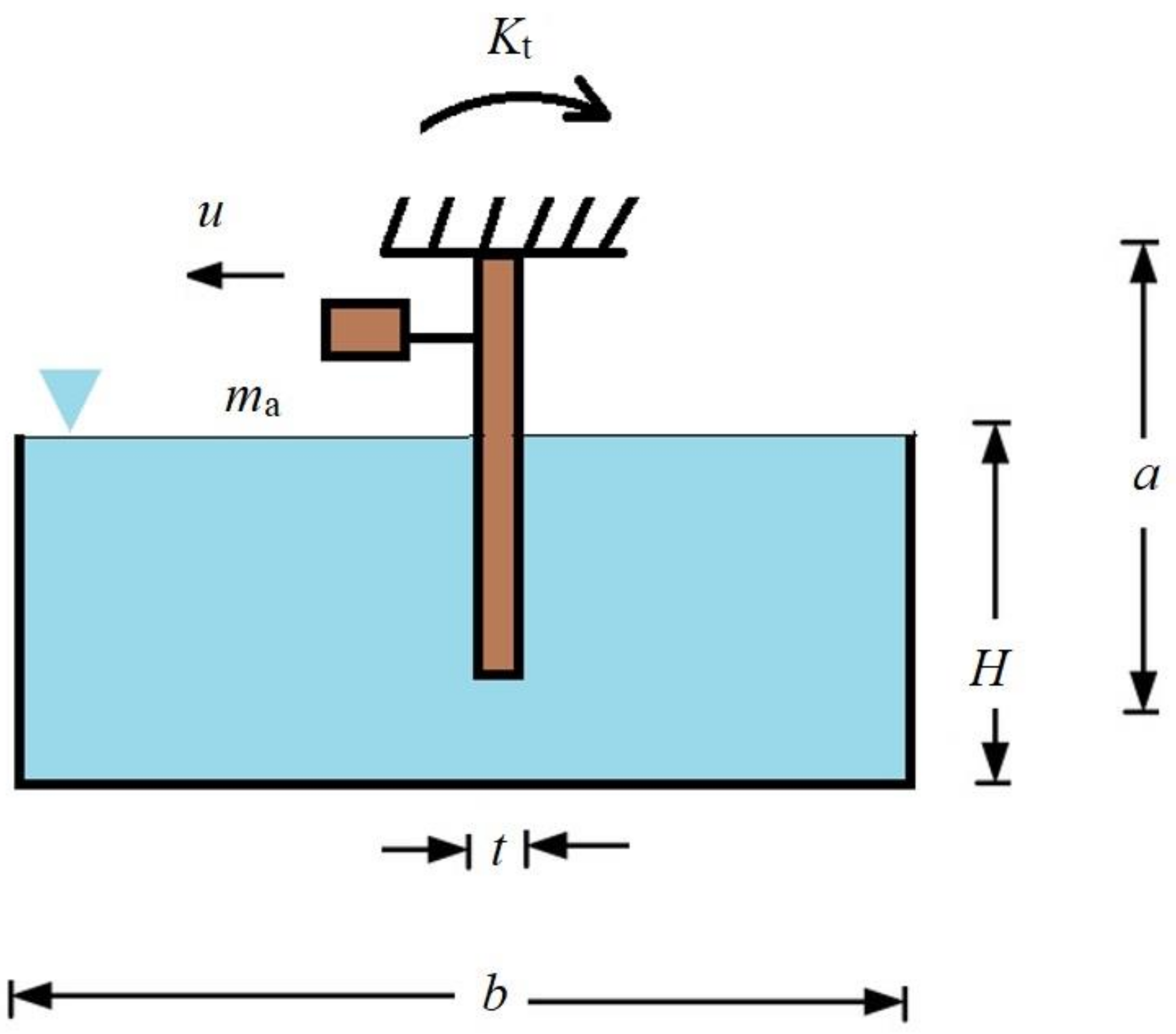
A flexible structure located inside of the liquid containers, the same as baffle structures, is considered here. Figure 1 shows the liquid level and tank specifications. Even though Jamalabadi [6] studied the coupled motion of sloshing and fluid–structure interaction, these problems were treated separately. In this study, the coupled sloshing and structural vibrations will be investigated. Let us consider a three-dimensional problem as shown below. The water is bounded by a rigid wall, a rigid bottom, and a flexible beam. Table 1 shows the parameters of the considered system. For the sloshing problem, in addition to considering the velocity potential founded from Laplace equation of the fluid, the solid dynamics outside of the fluid can affect the governing equations, especially at the interface of the structure and fluid. To extract the dynamic equation of the system and the basic equation in mode extraction from the classical eigenvalue problem, here, the energy approach is used. The boundary condition of inviscid fluid considered is slip boundary condition at the tank’s walls and kinematic boundary condition over the flexible submerged plate.
The kinetic energies of the system can be written as
and potential energies of the system can be written as
where is a vector consisting of generalized coordinates, is a vector consisting of moving mass displacements, is a vector consisting of plate displacement at the point of supporting mass, subscript represents the plate, is the mass density of the plate, is the plate height, is the plate width, is the thickness,
is the Young’s modulus, and is Poisson’s ratio, subscript represents the fluid, is the mass density of the fluid, H is the plate height inside the fluid, subscript a represents the active mass damper (AMD), ms is the supporting mass of the AMD, ma is moving mass of the AMD, the nondimensionalized mass matrices of the solid plate are
and the nondimensionalized stiffness of the solid plate is
The analysis is made for the first modes. Block Lanczos method could be used for mode extraction. It uses an algorithm where the Lanczos recursion is performed with a block of vectors. Assuming an isotropic, homogeneous, and inviscid fluid flow for the sloshing liquid, the nondimensionalized mass matrices of the fluid are
where the operator, similar to the “.*” operator in MATLAB, indicates the element-by-element multiplication. As the precision of finite element and boundary element methods are dependent on the physics of the sloshing geometry and grid size meshing and considering that a full 3D plate model is time-consuming, the analytical solution of Euler Beam in one dimension is adopted to reduce the time and cost needed for computation. The components of functions used in Equations (5) and (6) are
and the components of functions used in Equations (5) and (6) are
Here, the admissible functions are considered as the eigenfunction of a torsional spring-free beam in x direction ()
where = 4.5988, 7.6530, 10.7380, 13.8315, 16.9325, 20.0395, 23.1512, etc., and the admissible functions are considered as the eigenfunction of a free-free beam in z direction () with two rigid-body modes
and the normal modes () are
where = 4.730, 7.853, 10.996, 14.137, etc.
Additionally, in Equation (7) is the nonperiodic even Mathieu function (cosine-elliptic),
where is the periodic Mathieu function (sin-elliptic). Elliptic functions used in Equations (7) and (14) are expressed by the following Fourier series
By using the Lagrangian for the system
Lagrange’s equation
and introducing the disturbance (d), equations of motion can then be written as
By solving the free vibration problem of Equation (19), in regard to Table 1 with value parameters of the elements in the system, natural frequencies and mode shapes can be obtained. By neglecting Mf, the natural frequencies and mode shapes for vibrating in vacuo () can be obtained. The eigenvector of matrix U satisfies the orthonormality condition:
where
If we apply the modal transformation, , to the eigenvalue problem of the plate vibrating in a fluid, Equation (19), and premultiply it by , we can obtain
where the nondimensionalized added virtual mass incremental (NAVMI) factor represents the diagonal components of .
where
The following equations of motion are obtained in matrix form:
where and . Here, the mathematical model is similar to cantilever beams and uses one degree of freedom for modeling moving mass devices to apply the active control. As the paper regards the vibration dumping technique of a rectangular plate submerged in water, a controller design is conducted. To design a multi-input (applied acceleration of finite moving mass) multi-output (measured acceleration at finite node) system, a negative acceleration feedback control (NAF) is used. The components of Equation (26) are separated by a controlled (with subscript 1) and uncontrolled mode (with subscript 2) as
where NAF is coupled to the first group with its own damping factors () and acceleration gain ()
The balance equation is used to find the gain matrix
The final coupled equations are
By reconstructing the components of V vector, controlled contains [V1 V2], V with subscript 1 from Equation (31) and uncontrolled with subscript 2 from Equation (28), the decentralized multi-input multi-output (MIMO) negative acceleration feedback control (NAF) controller coupled equations are presented as
Both controllers are static stable (frequency independent) if the determinant of the first matrix is positive.
3. Results and Discussion
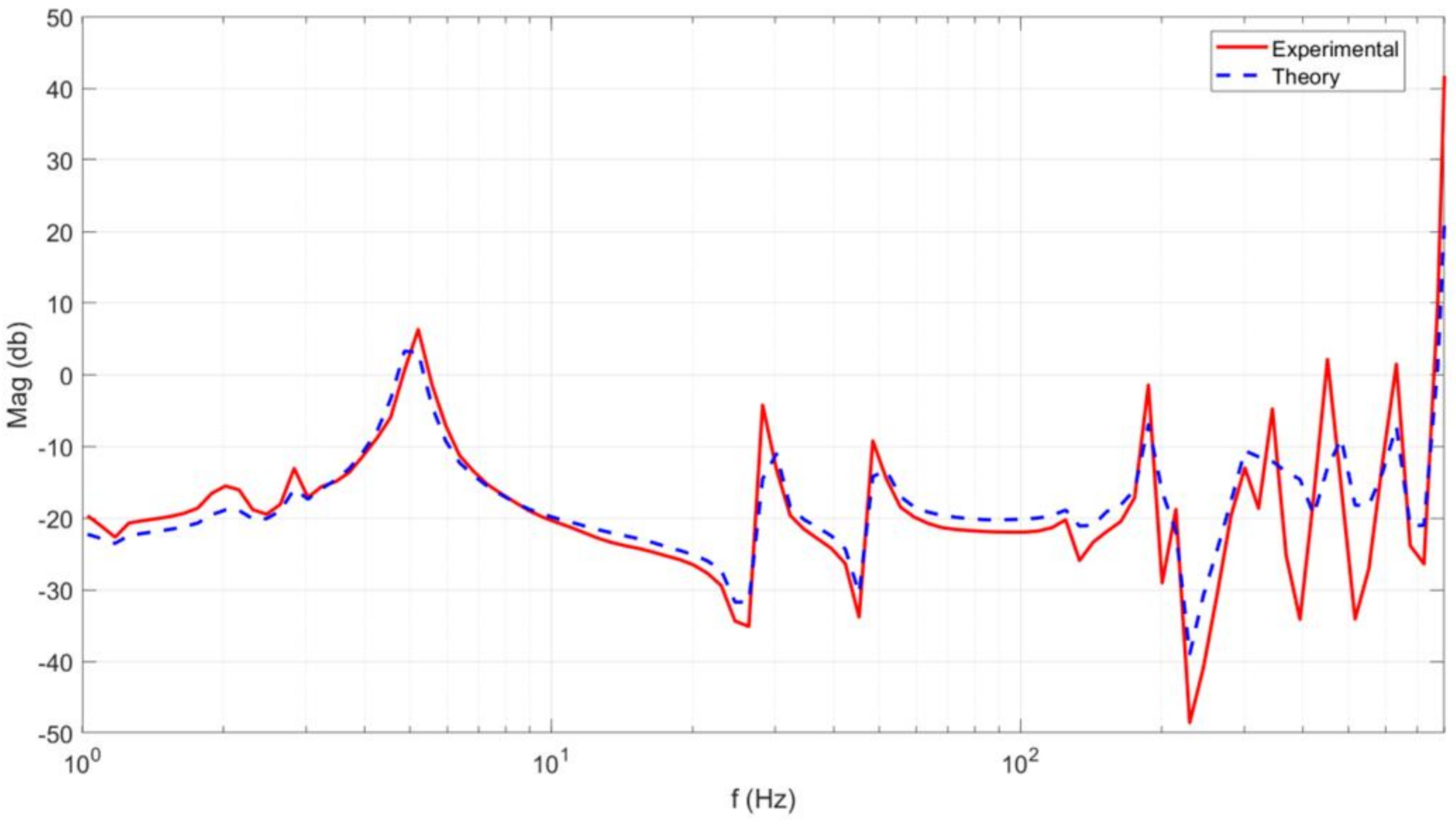
This paper regards a numerical investigation on submerged systems by moving mass. The first step in this work is estimating the frequency response function of the free plate in air and comparing the numerical and experimental [16] results. A mechanical structure usually is modeled as an assembly of masses, springs, and dampers by modal method. The output analysis of modal method is usually plotted in frequency response function (FRF) which is the frequency response of the mechanical structure to the vibrational dynamic force. The FRF map is used to avoid resonance and noises. Figure 2 presents a comparison of magnitude of the frequency response function of the free plate, for both the theory and experiment. The FRF in Figure 2 can be considered as the superposition of the influence of vibration modes. In any case, the exchange work at a higher recurrence extend has an alternate size, which infers that the displaying precision crumbles for higher modes or the exploratory outcomes are bad for higher modes. Experimental modal analysis results in Figure 2 are based on the structure’s excitation with a calibrated PZT actuator and the measurement of its response with a calibrated PZT sensor submerged in water. From Figure 2, one can see some characteristic frequencies in the low recurrence run. This is most likely because of the sloshing modes, which were dismissed in the detailing.
By solving the free vibration problem of Equation (19), the eigenmodes of the system could be obtained. The inputs of the system of equations are thickness of the aluminum plate, Poisson ratio of the aluminum plate, density of the aluminum plate, module of elasticity of the aluminum plate, density of the fluid, dimension of the aluminum plate, observed point of vibration, moving mass of active mass damper, and dimensions (height, length, and depth) of the fluid tank. The numerical model presented here is just the needed number of required modes as input, there is no need for a computational grid as the analytical solution is provided. Moreover, the computational time is around 200 s for calculating the first 15 modes on a Core i7 PC.
Table 2 shows the numerical values of natural frequencies of the system for various draught ratios. At the draught of 10%, it was found that the first natural frequency of the test structure is 0.5558 Hz, while the second natural frequency of the structure is 1.3579. A modal control like NAF is based on the identification of natural frequencies of the system and uses this parameter to design a scheme of control. In Table 3, the numerical and experimental natural frequency values of the system are presented. In addition, Table 3 presents the comparison of the numerical and experimental values of natural frequencies of the system for 50% draught. As presented, the natural frequencies measured by observing the transfer function [16] and the theoretical results of the natural frequencies are consistent.
In the next steps, the frequency responses of the submerged plate with various insert lengths are compared with experimental setup results. The sloshing may happen in our investigation since the plate is drenched in the water tank, presented in Figure 3. As mentioned previously, measurement of the frequency response curve is carried out by the frequency analyzer. The characteristic frequencies can be distinguished by finding the pinnacles, and these are in great concurrence with the hypothetical regular frequencies, which empower us to quantify the adjustments in the normal frequencies coming about because of changes in the water tallness, as shown in Figure 3. Figure 3 presents a comparison of the magnitude of frequency response function of the partially submerged plate (H = 0.15 m). Figure 3 obviously demonstrates that the hypothetical forecasts are reliable with the consequences of the trial, which approves the sufficiency of the additional virtual mass framework.
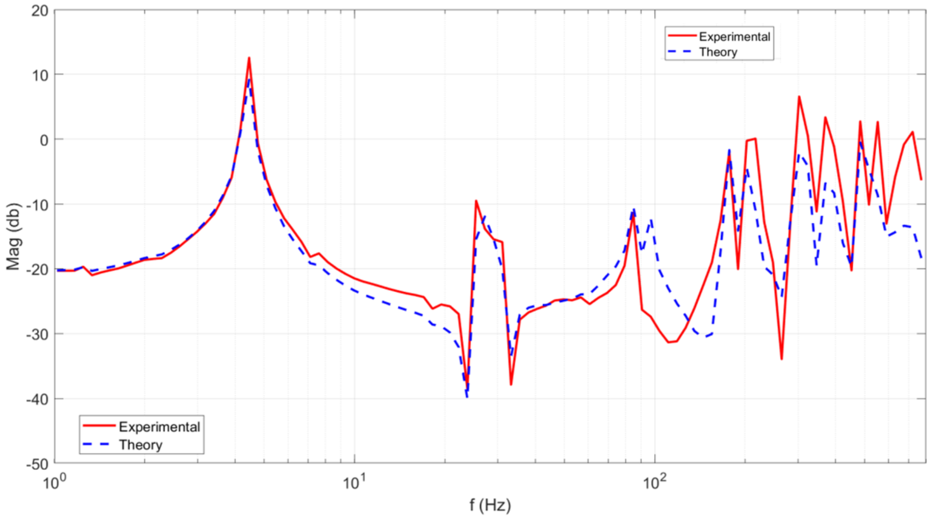
Figure 4 exposes the comparison of theory and experiment in the magnitude of frequency response function of the partially submerged plate (H = 0.3 m). Nevertheless, the frequency response function at higher frequencies has a diverted magnitude, which implies that the modeling accuracy worsens for higher modes. Experimental results are in good agreement with the predicted numerical results as shown in Figure 2, Figure 3 and Figure 4. This proves that vibration of the plate structure can be theoretically modeled by using the proposed method.
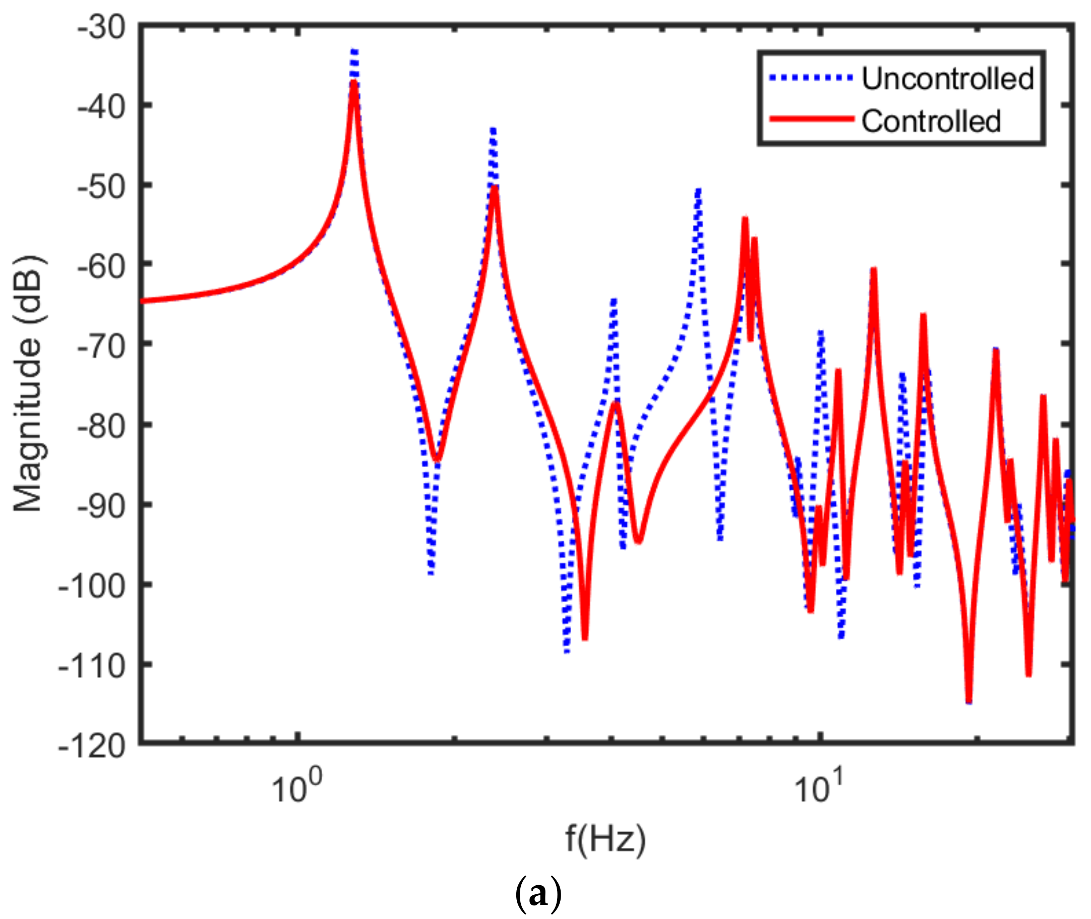
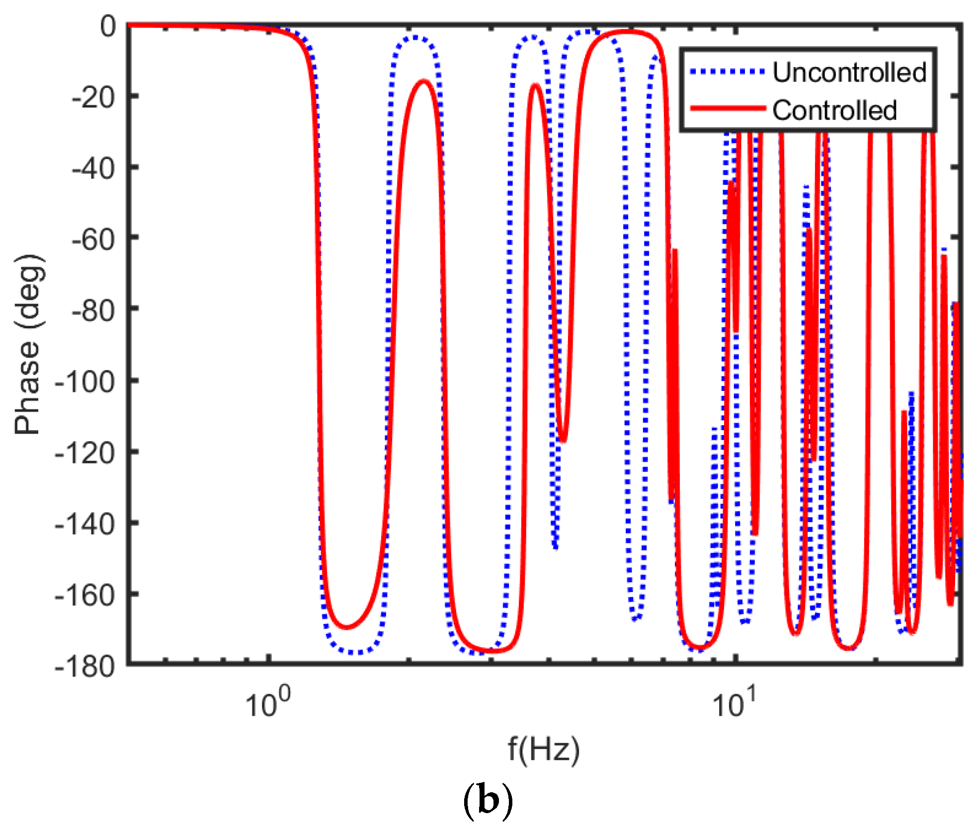
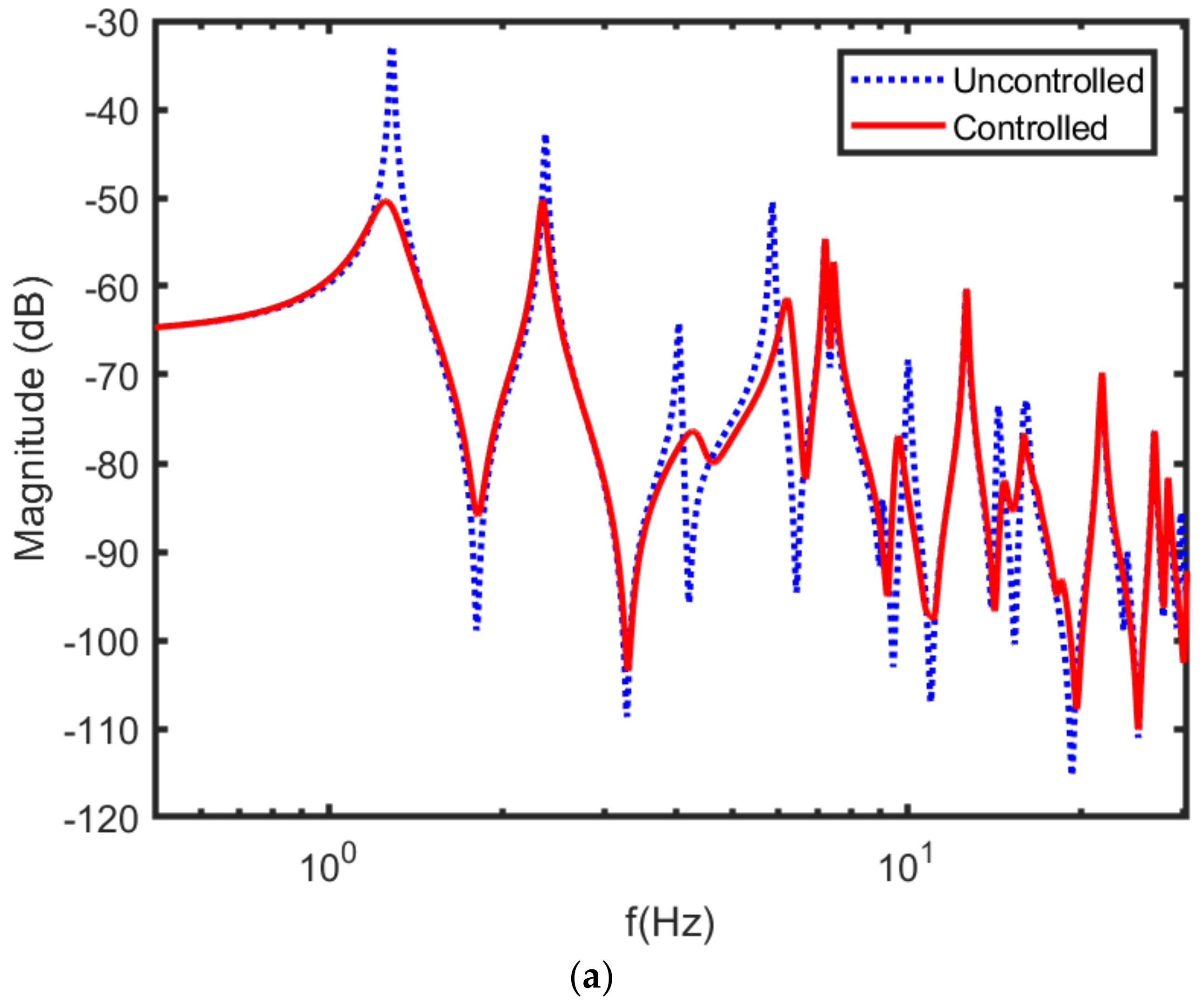
After numerical model validation against the experimental results, the studies regarding vibration damping by a moving mass are conducted. Figure 5, Figure 6 and Figure 7 show the vibrations versus frequency, demonstrated for the uncontrolled plate (blue lines) and the controlled plate (red line), using the methods defined earlier. Table 4 shows the control parameters. Figure 5 displays the magnitude and phase of the frequency response function of the partially submerged plate (H = 0.3 m) controlled by MIMO modal-space NAF. Figure 5 also shows natural mode shapes of the plate with and without MIMO modal-space NAF, since NAF control is operative in overwhelming the first natural mode. As shown in Figure 5, MIMO modal-space NAF affected only higher modes, particularly the sixth and seventh modes. The damping factor for all frequencies was assumed to be 0.005, and a filter damping factor of 0.4 was chosen. As shown in Figure 5, the introduction of MIMO modal-space NAF increased the damping of the three lowest modes. Uncontrolled peak-amplitudes could be abridged meaningfully once the system is controlled by the MIMO modal-space NAF control.
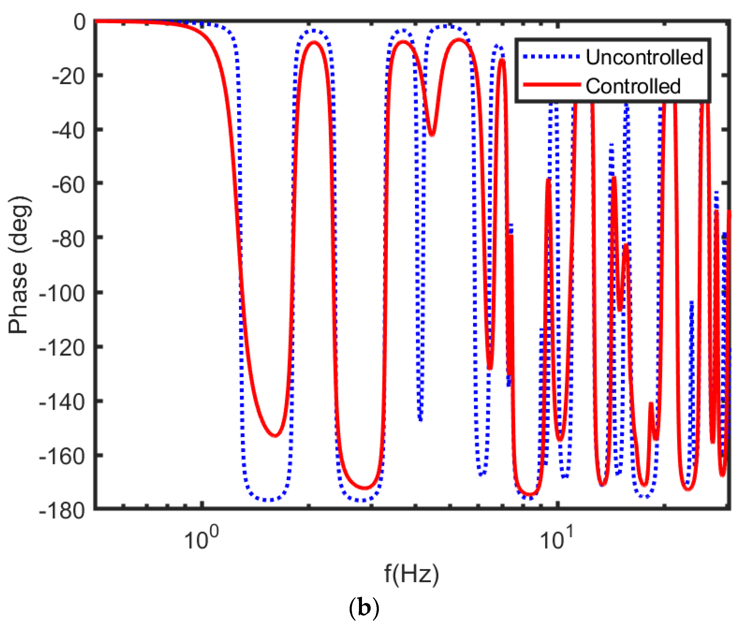
The immersed, elastic, thin-walled plate with normal thickness used in industry now can be controlled by the NAF method. The structural boundary condition at the top and the fluid interface, as well as the condition of moving mass, affect the control procedure. Active vibration control of a partially and completely submerged plate is presented in Figure 6. Figure 6 reveals the frequency response function of the partially submerged plate (H = 0.3 m) controlled by decentralized MIMO modal-space NAF, (a) magnitude and (b) phase. As shown in Figure 6, vibrations are rapidly suppressed by the fully coupled MIMO modal-space NAF controller. Figure 6 shows the frequency response function at the excitation point when the decentralized MIMO NAF controller is used. It is found that mistuning of the NAF controller cannot cause any destructive problems. Additionally, the advantage of using a NAF controller and AMD controller simultaneously is established hypothetically.
The precondition to the AMD–NAF controller is accurate knowledge of the moving mass. It is found that the controller which was effective in controlling the AC servo motor was not as effective as the linear servo motor experimentally [20]. Hence, the AMD–NAF technique is measured to touch the requested location. Figure 7 illustrates the impulse response by decentralized MIMO NAF controller of the partially submerged plate (H = 0.3 m). The fast damping of the impulse response of the vibration in Figure 7 is clear. It can be seen that the decentralized MIMO NAF controller is actually an effective method for suppressing vibrations. In addition, numerical results demonstrated that the NAF technique can be effective in tracking control of the moving mass of the AMD.
4. Conclusions
In this study, active vibration control of a rectangular plate submerged in water was investigated. Mass dampers were attached to the plate, and the system is modeled via the assumed mode. Water is modeled as an inviscid fluid with moving boundaries at fluid–solid interaction surfaces, and applied forces on the plate are calculated by Bernoulli equation. The natural frequency of the plate in vacuum and in water (for partial and submerged cases) found from numerical calculations are compared with experimental results to prove the accuracy of the model. To actively control the plate vibration by a moving mass with static stable methods, the displacement data of some points were used as input. The advantage of the AMD–NAF controller is that it does not need an extra procedure to calculate displacement or velocity from the input signal. The following results are obtained:
- Inviscid fluid modeling with fluid–solid interaction by Bernoulli forces is an effective approach to frequency response modeling of sloshing systems coupled by structure.
- The negative acceleration feedback control algorithm in modal-space is an effective approach to controlling the vibrating plate problem submerged in a vessel.
- The decentralized negative acceleration feedback control algorithm in modal-space is an effective approach to controlling the vibrating plate problem submerged in a vessel.
Funding
This research received no external funding.
Institutional Review Board Statement
Not applicable.
Informed Consent Statement
Not applicable.
Data Availability Statement
The data presented in this study are available on request from the corresponding author.
Conflicts of Interest
On behalf of the author, the corresponding author states that there is no conflict of interest.
Nomenclature
| a | Dimension of the aluminum plate for draught of 50% (m) |
| b | Length of the fluid tank (m) |
| vector consisting of plate displacement at the point of supporting mass | |
| C | capacitance |
| nonperiodic even Mathieu function (cosine-elliptic) | |
| d33 | piezoelectric charge coefficient |
| E | Young’s modulus, Module of elasticity (GPa) |
| F | force |
| g | Gravity constant (ms−2) |
| H | Height of the fluid tank (m) |
| K | stiffness |
| L | Depth of the fluid tank (m) |
| vector consisting of generalized coordinates | |
| p | pressure (Pa) |
| Q | electric charge on the electrodes of the transducer |
| periodic Mathieu function (sin-elliptic) | |
| t | thickness of the aluminum plate (m) |
| vector consisting of moving mass displacements | |
| V | voltage |
| Greek symbols | |
| total displacement | |
| ρ | density (kg/m3) |
| ν | Poisson ratio of the aluminum plate |
| eigenfunction of a torsional Spring-free beam in x direction | |
| eigenvalues of a free-free beam in z direction | |
| eigenfunction of a free-free beam in z direction | |
| Subscript | |
| a | moving mass of the active mass damper |
| f | base fluid |
| p | aluminum plate |
| s | supporting mass |
References
- Jamalabadi, M.Y.A. Optimal design of Vibrating Beam behind a cylinder. Ocean Eng. 2020, 195, 106759. [Google Scholar] [CrossRef]
- Jamalabadi, M.Y.A. Effect of Tip Mass Length Ratio on Low Amplitude Galloping Piezoelectric Energy Harvesting. Acoustics 2019, 1, 45. [Google Scholar] [CrossRef] [Green Version]
- Jamalabadi, M.Y.A. Positive Position Feedback Control of a Galloping Structure. Acoustics 2018, 1, 5. [Google Scholar] [CrossRef] [Green Version]
- Gallerano, F.; Cannata, G.; Barsi, L.; Palleschi, F.; Iele, B. Simulation of wave motion and wave breaking induced energy dissipation. WSEAS Trans. Fluid Mech. 2019, 14, 62. [Google Scholar]
- Jamalabadi, M.Y.A. LBM simulation of piezo fan in square enclosure. Int. J. Numer. Methods Heat Fluid Flow 2019, 30, 401–426. [Google Scholar] [CrossRef]
- Jamalabadi, M.Y.A. The frequency response of a cavitating hydrofoil. Noise Vib. Worldw. 2014, 45, 21–27. [Google Scholar] [CrossRef]
- Gallerano, F.; Cannata, G.; Palleschi, F. Hydrodynamic effects produced by submerged breakwaters in a coastal area with a curvilinear shoreline. J. Mar. Sci. Eng. 2019, 7, 337. [Google Scholar] [CrossRef] [Green Version]
- Jamalabadi, M.Y.A. Optimal Design of Isothermal Sloshing Vessels by Entropy Generation Minimization Method. Mathematics 2019, 7, 380. [Google Scholar] [CrossRef] [Green Version]
- Jamalabadi, M.Y.A. An Improvement of Port-Hamiltonian Model of Fluid Sloshing Coupled by Structure Motion. Water 2018, 10, 1721. [Google Scholar] [CrossRef] [Green Version]
- Jamalabadi, M.Y.A. Analytical Solution of Sloshing in a Cylindrical Tank with an Elastic Cover. Mathematics 2019, 7, 1070. [Google Scholar] [CrossRef] [Green Version]
- Mao, Q.; Pietrzko, S. Positive Position Feedback (PPF) Control. In Control of Noise and Structural Vibration; Springer: London, UK, 2013. [Google Scholar]
- Belibassakis, K.A.; Gerostathis, T.; Kostas, K.; Politis, C.; Kaklis, P.; Ginnis, A.; Feurer, C. A BEM-isogeometric method for the ship wave-resistance problem. Ocean Eng. 2013, 60, 53–67. [Google Scholar] [CrossRef]
- Canales, F.G.; Mantari, J.L. Laminated composite plates in contact with a bounded fluid: Free vibration analysis via unified formulation. Compos. Struct. 2017, 162, 374–387. [Google Scholar] [CrossRef]
- Gong, Y.; Dong, C. An isogeometric boundary element method using adaptive integral method for 3D potential problems. J. Comput. Appl. Math. 2017, 319, 141–158. [Google Scholar] [CrossRef]
- Zhao, G.; Du, X.; Wang, W.; Liu, B.; Fang, H. Application of isogeometric method to free vibration of Reissner–Mindlin plates with non-conforming multi-patch. Comput. Des. 2017, 82, 127–139. [Google Scholar] [CrossRef]
- Kwak, M.K.; Yang, D.-H. Dynamic modelling and active vibration control of a submerged rectangular plate equipped with piezoelectric sensors and actuators. J. Fluids Struct. 2015, 54, 848–867. [Google Scholar] [CrossRef]
- Yang, J.; Ning, D.; Sun, S.; Zheng, J.; Lu, H.; Nakano, M.; Zhang, S.; Du, H.; Li, W. A semi-active suspension using a magnetorheological damper with nonlinear negative-stiffness component. Mech. Syst. Signal Process. 2021, 147, 107071. [Google Scholar] [CrossRef]
- Yoon, D.-S.; Kim, G.-W.; Choi, S.-B. Response time of magnetorheological dampers to current inputs in a semi-active suspension system: Modeling, control and sensitivity analysis. Mech. Syst. Signal Process. 2021, 146, 106999. [Google Scholar] [CrossRef]
- Xu, L.; Cui, Y.; Wang, Z. Active tuned mass damper based vibration control for seismic excited adjacent buildings under actuator saturation. Soil Dyn. Earthq. Eng. 2020, 135, 106181. [Google Scholar] [CrossRef]
- Zhang, Z. Numerical and experimental investigations of the sloshing modal properties of sloped-bottom tuned liquid dampers for structural vibration control. Eng. Struct. 2020, 204, 110042. [Google Scholar] [CrossRef]
- Wang, W.; Dalton, D.; Chen, Z.; Wang, X.; Chen, Z.; Song, G. Experimental study on vibration control of a submerged pipeline model by eddy current tuned mass damper. Appl. Sci. 2017, 7, 987. [Google Scholar] [CrossRef] [Green Version]
- Song, G.; Zhang, P.; Li, L.Y.; Singla, M.; Patil, D.; Li, H.; Mo, Y.L. Vibration control of a pipeline structure using pounding tuned mass damper. J. Eng. Mech. 2016, 142, 04016031. [Google Scholar] [CrossRef]
- Derakhti, M.; Kirby, J.T.; Shi, F.; Ma, G. NHWAVE: Consistent boundary conditions and turbulence modeling. Ocean Model. 2016, 106, 121–130. [Google Scholar] [CrossRef]
- Ma, G.; Shi, F.; Kirby, J.T. Shock-capturing non-hydrostatic model for fully dispersive surface wave processes. Ocean Model. 2012, 43, 22–35. [Google Scholar] [CrossRef]
- Brennen, C.E. A Review of Added Mass and Fluid Inertial Forces; Department of the Navy: Port Hueneme, CA, USA, 1982. [Google Scholar]
- Lin, Z.; Liao, S. Calculation of added mass coefficients of 3d complicated underwater bodies by fmbem. Commun. Nonlinear Sci. Numer. Simul. 2011, 16, 187–194. [Google Scholar] [CrossRef]
Figure 1.
Schematic of the three-dimensional sloshing and structural vibrations front view.

Figure 2.
Comparison of magnitude of frequency response function of the free plate, for theory and experiment.
Figure 2.
Comparison of magnitude of frequency response function of the free plate, for theory and experiment.

Figure 3.
Comparison of frequency response function magnitude of the partially submerged plate (H = 0.15 m), theory and experiment.
Figure 3.
Comparison of frequency response function magnitude of the partially submerged plate (H = 0.15 m), theory and experiment.

Figure 4.
Comparison of frequency response function magnitude of the partially submerged plate (H = 0.3 m), theory and experiment.
Figure 4.
Comparison of frequency response function magnitude of the partially submerged plate (H = 0.3 m), theory and experiment.

Figure 5.
Frequency response function of the partially submerged plate (H = 0.3 m) controlled by multi-input multi-output (MIMO) modal-space negative acceleration feedback control (NAF), (a) magnitude and (b) phase.
Figure 5.
Frequency response function of the partially submerged plate (H = 0.3 m) controlled by multi-input multi-output (MIMO) modal-space negative acceleration feedback control (NAF), (a) magnitude and (b) phase.


Figure 6.
Frequency response function of the partially submerged plate (H = 0.3 m) controlled by decentralized MIMO modal-space NAF, (a) magnitude and (b) phase.
Figure 6.
Frequency response function of the partially submerged plate (H = 0.3 m) controlled by decentralized MIMO modal-space NAF, (a) magnitude and (b) phase.


Figure 7.
Impulse response by decentralized MIMO NAF controller of the partially submerged plate (H = 0.3 m).
Figure 7.
Impulse response by decentralized MIMO NAF controller of the partially submerged plate (H = 0.3 m).


Table 1.
Experimental setup parameters [16].
Table 1.
Experimental setup parameters [16].
| Parameter | Value | Unit | Description |
|---|---|---|---|
| t | 2 | mm | Thickness of the aluminum plate |
| 0.33 | − | Poisson ratio of the aluminum plate | |
| ρp | 2700 | kg/m3 | Density of the aluminum plate |
| Ep | 68.9 | GPa | Module of elasticity of the aluminum plate |
| ρf | 1000 | kg/m3 | Density of the fluid |
| a | 900 | mm | Dimension of the aluminum plate for draught of 50% |
| b | 300 | mm | Dimension of the fluid tank |
| H | 450 | mm | Dimension of the fluid tank |
| L | 450 | mm | Dimension of the fluid tank |
Table 2.
Numerical values of natural frequencies of the system for various draught ratios.
| 10% Draught | 20% Draught | 30% Draught | 40% Draught | 50% Draught | |
|---|---|---|---|---|---|
| 1 | 3.4919 | 3.4664 | 3.4509 | 3.4417 | 3.4360 |
| 2 | 8.5322 | 14.8380 | 21.2059 | 21.5038 | 21.4772 |
| 3 | 21.4308 | 21.5970 | 21.5427 | 27.6445 | 34.1324 |
| 4 | 27.3504 | 48.4160 | 60.4955 | 60.3272 | 60.2020 |
| 5 | 31.1654 | 60.5937 | 66.6982 | 85.4110 | 104.4240 |
| 6 | 54.4540 | 93.3672 | 118.9479 | 118.6553 | 118.3542 |
| 7 | 61.6181 | 93.7573 | 121.4258 | 151.4252 | 182.4435 |
| 8 | 64.5492 | 119.1964 | 188.4479 | 196.7006 | 196.2312 |
| 9 | 71.5548 | 127.6663 | 195.0043 | 227.2713 | 268.3955 |
| 10 | 93.7973 | 154.1316 | 208.4070 | 322.2323 | 377.0116 |
Table 3.
Numerical and experimental values of natural frequencies of the system for 50% draught.
| Numerical | Experimental | |
|---|---|---|
| 1 | 3.4360 | 3.5068 |
| 2 | 21.4772 | 20.4717 |
| 3 | 34.1324 | 33.3710 |
| 4 | 60.2020 | 57.4699 |
| 5 | 104.4240 | 100.2170 |
| 6 | 118.3542 | 122.1825 |
| 7 | 182.4435 | 185.9980 |
| 8 | 196.2312 | 192.6422 |
| 9 | 268.3955 | 280.4793 |
| 10 | 377.0116 | 359.4597 |
Table 4.
Control parameters.
| Parameter | Description |
|---|---|
| (xp,yp) | Observed point of vibration |
| ma | Active mass damper |
| u | Displacement of moving mass |
Publisher’s Note: MDPI stays neutral with regard to jurisdictional claims in published maps and institutional affiliations. |
© 2021 by the author. Licensee MDPI, Basel, Switzerland. This article is an open access article distributed under the terms and conditions of the Creative Commons Attribution (CC BY) license (http://creativecommons.org/licenses/by/4.0/).
Share and Cite
MDPI and ACS Style
Abdollahzadeh Jamalabadi, M.Y. Active Control of Submerged Systems by Moving Mass. Acoustics 2021, 3, 42-57. https://0-doi-org.brum.beds.ac.uk/10.3390/acoustics3010005
AMA Style
Abdollahzadeh Jamalabadi MY. Active Control of Submerged Systems by Moving Mass. Acoustics. 2021; 3(1):42-57. https://0-doi-org.brum.beds.ac.uk/10.3390/acoustics3010005
Chicago/Turabian StyleAbdollahzadeh Jamalabadi, Mohammad Yaghoub. 2021. "Active Control of Submerged Systems by Moving Mass" Acoustics 3, no. 1: 42-57. https://0-doi-org.brum.beds.ac.uk/10.3390/acoustics3010005