Development of an Exoskeleton-Type Assist Suit Utilizing Variable Stiffness Control Devices Based on Human Joint Characteristics †

 ,
, 
Abstract
:1. Introduction
- A prototype of an assistive suit for lower limbs based on the one-sided spring antagonized joint is developed. The prototype is tested to confirm that its behaviors are similar to the theoretical one-sided spring antagonized joint.
- The effectiveness of the assist by controlling the stiffness and antagonized angle of the one-sided spring antagonized joint is confirmed. For this purpose, we perform evaluation experiments using the prototype to measure EMG in assisting standing-up and gait motions.
2. One-Sided Spring Antagonized Joint
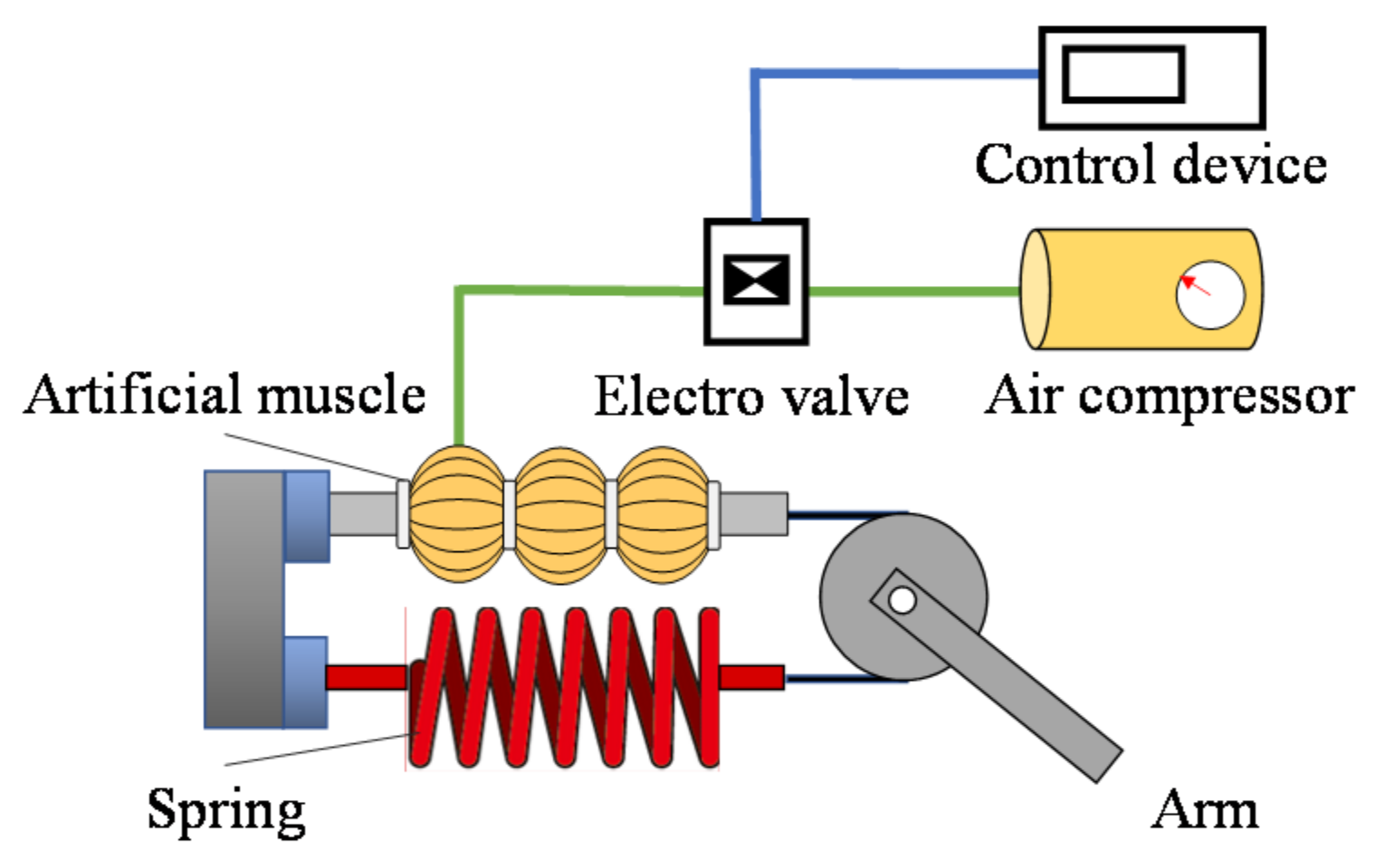
2.1. Structure
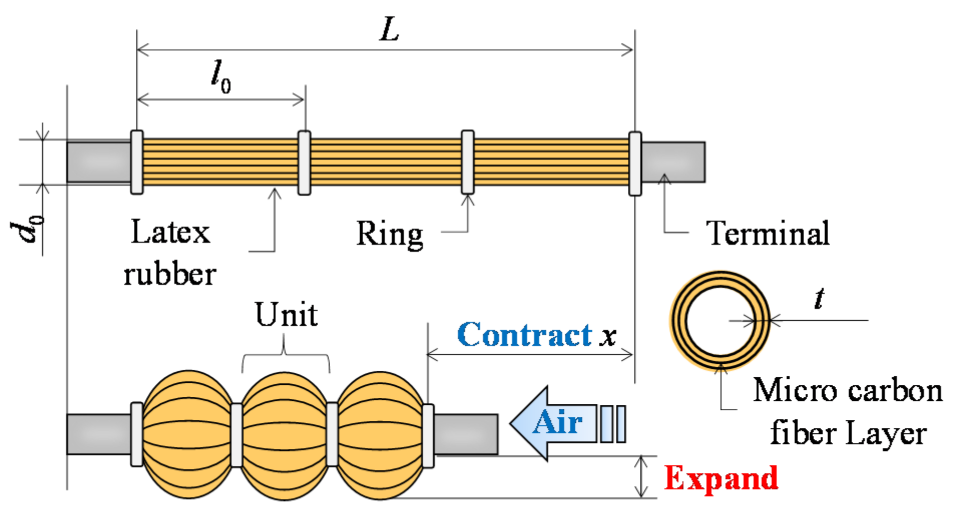
2.2. Straight Fiber-Type Artificial Muscle
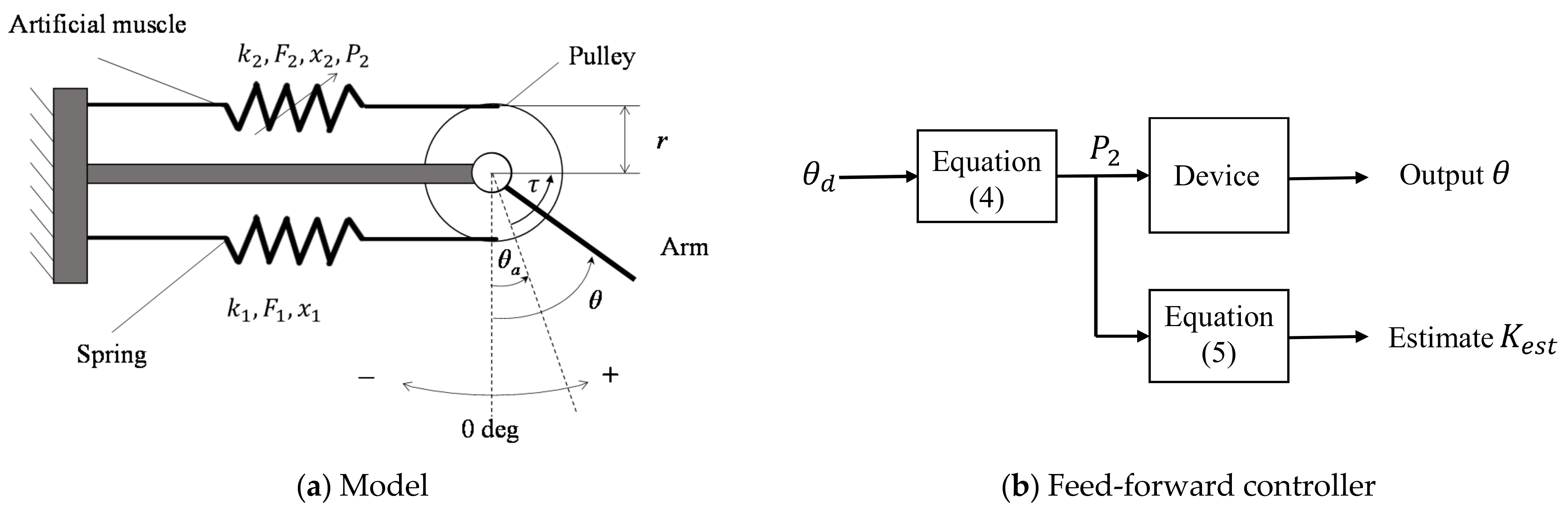
2.3. Modeling
2.4. Characteristic
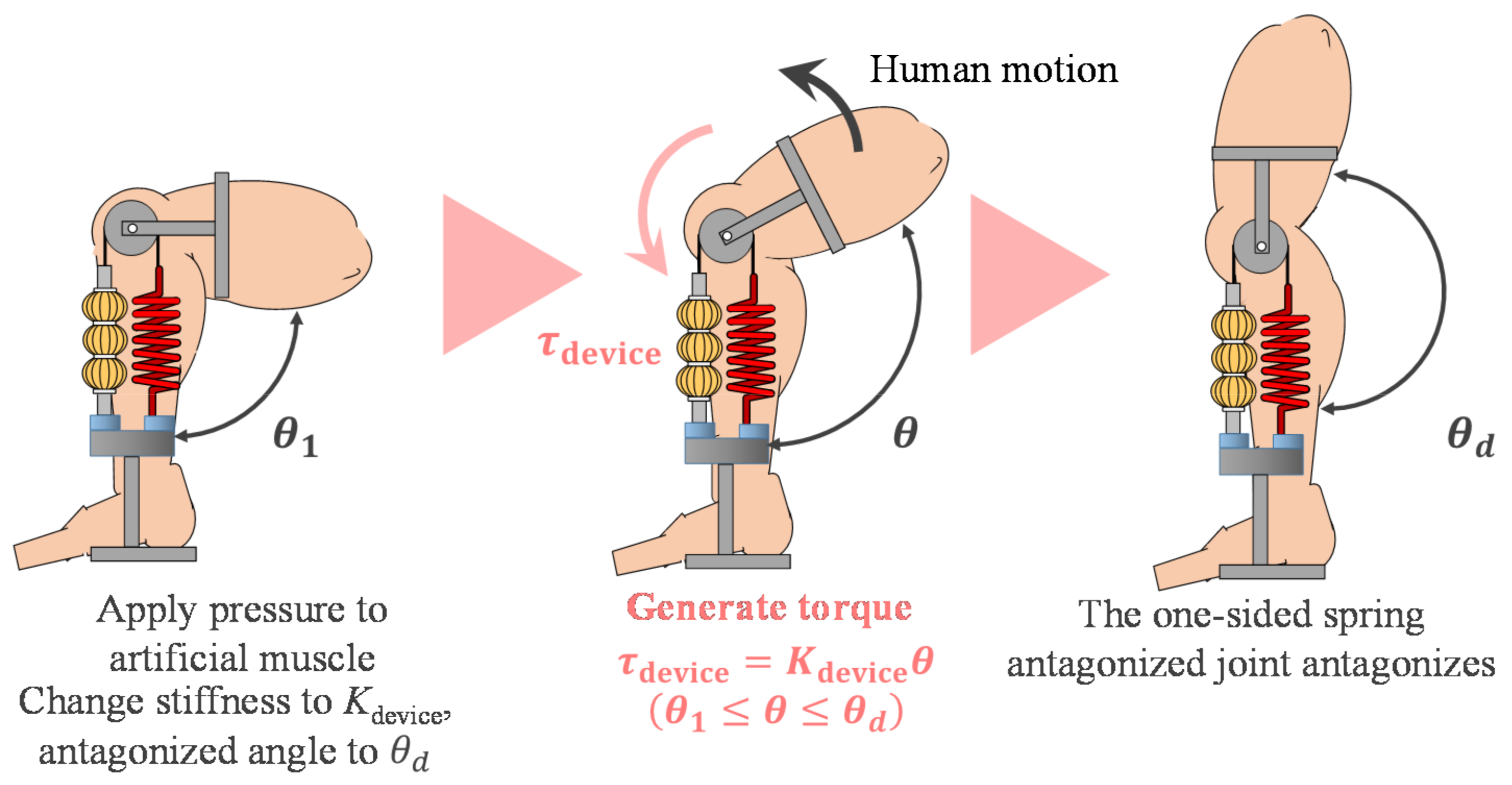
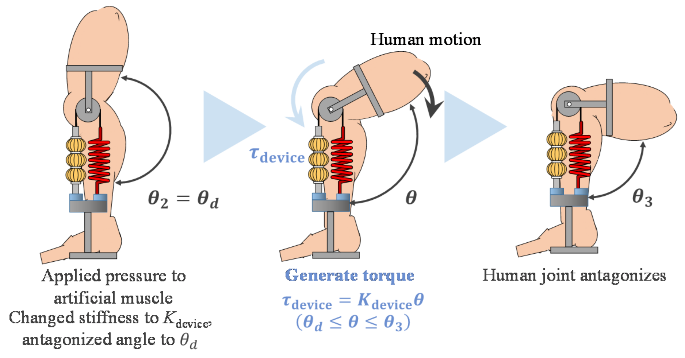
2.5. Assistive Method
3. Prototype
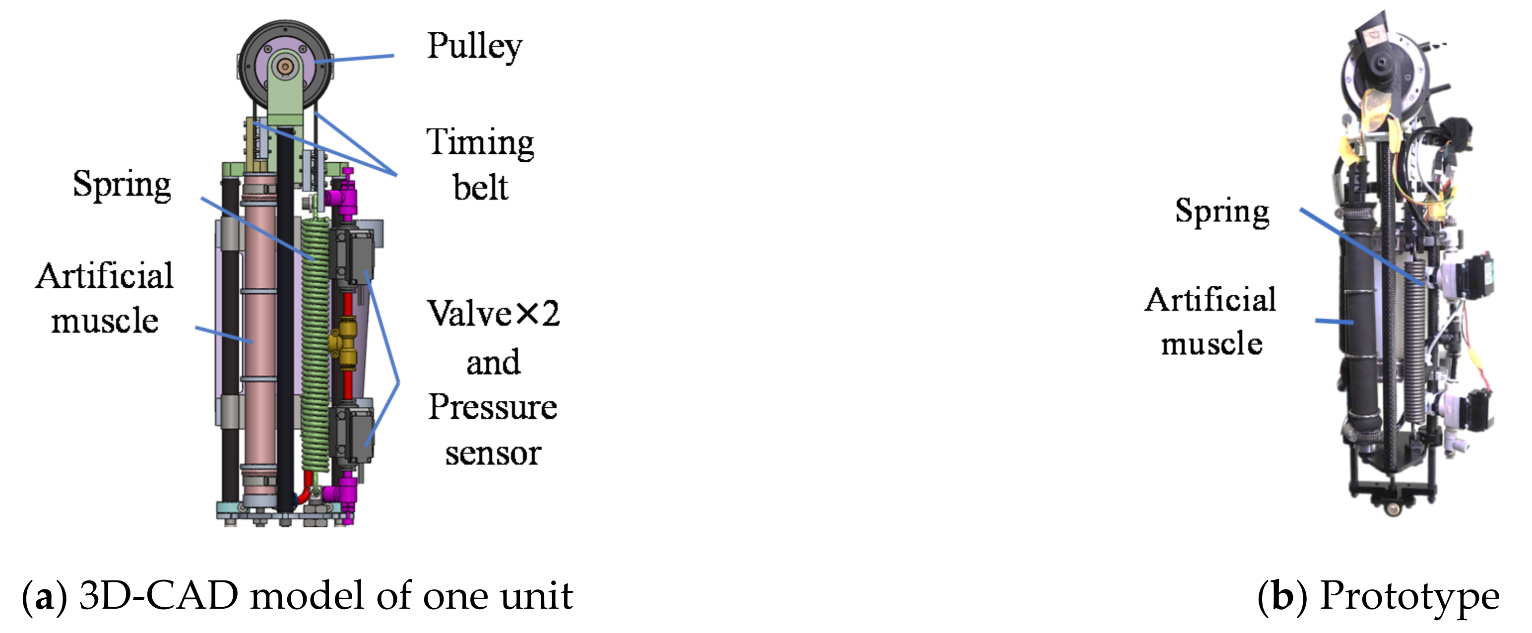
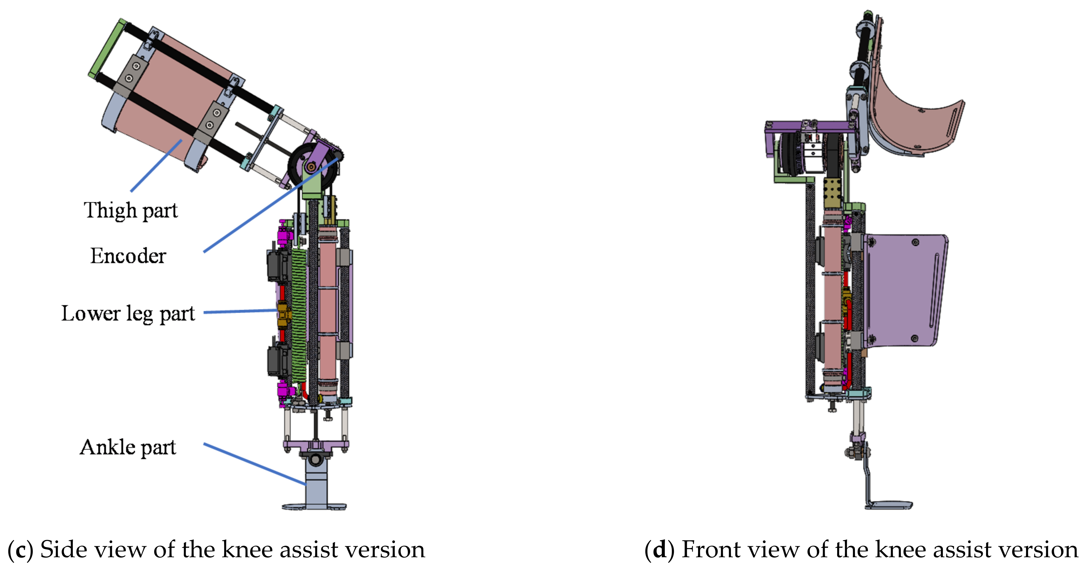
3.1. Structure
3.2. Characteristic Test
3.2.1. Purpose
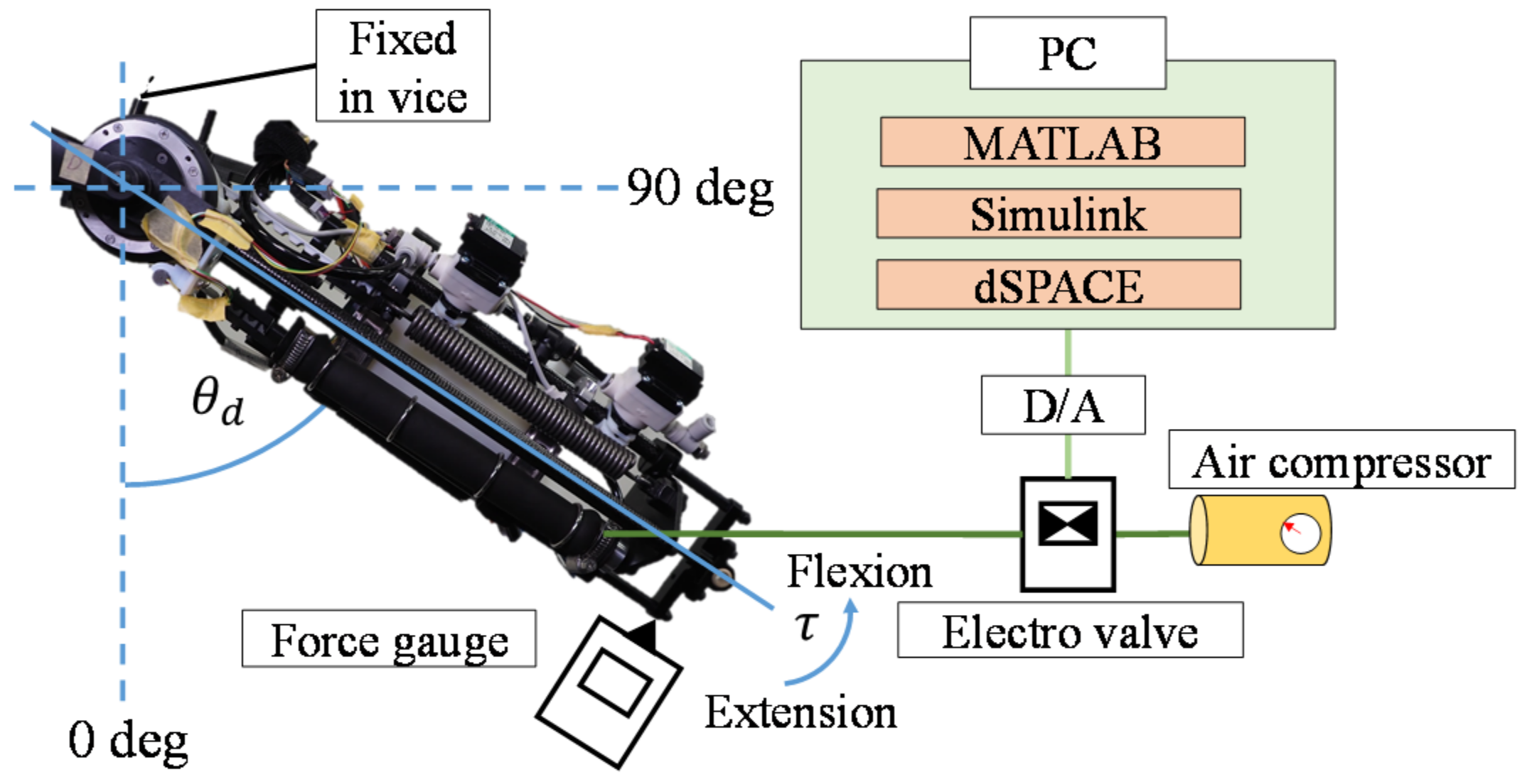
3.2.2. Experimental Environment
3.2.3. Experimental Method
3.2.4. Result and Discussion
4. Assist Evaluation
4.1. Purpose
4.2. Assist of Standing-up Motion
4.2.1. Subjects
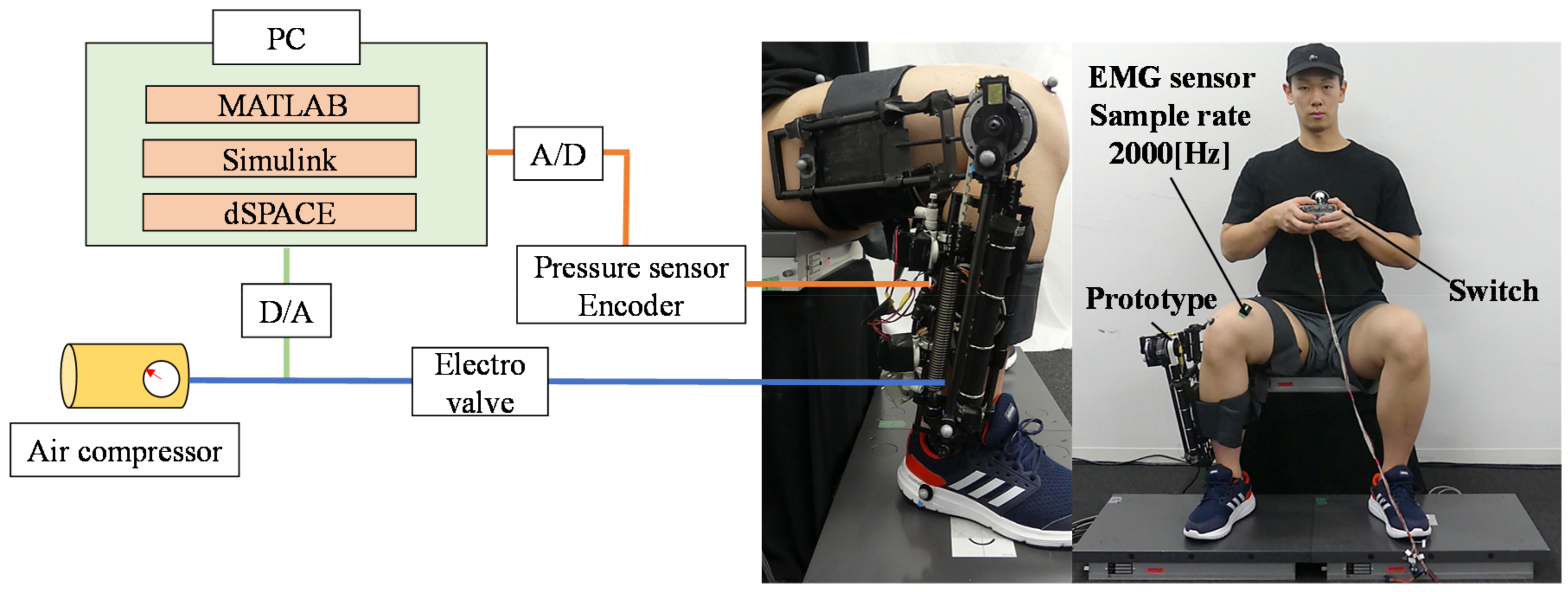
4.2.2. Experimental Environment
4.2.3. Assist Target Values
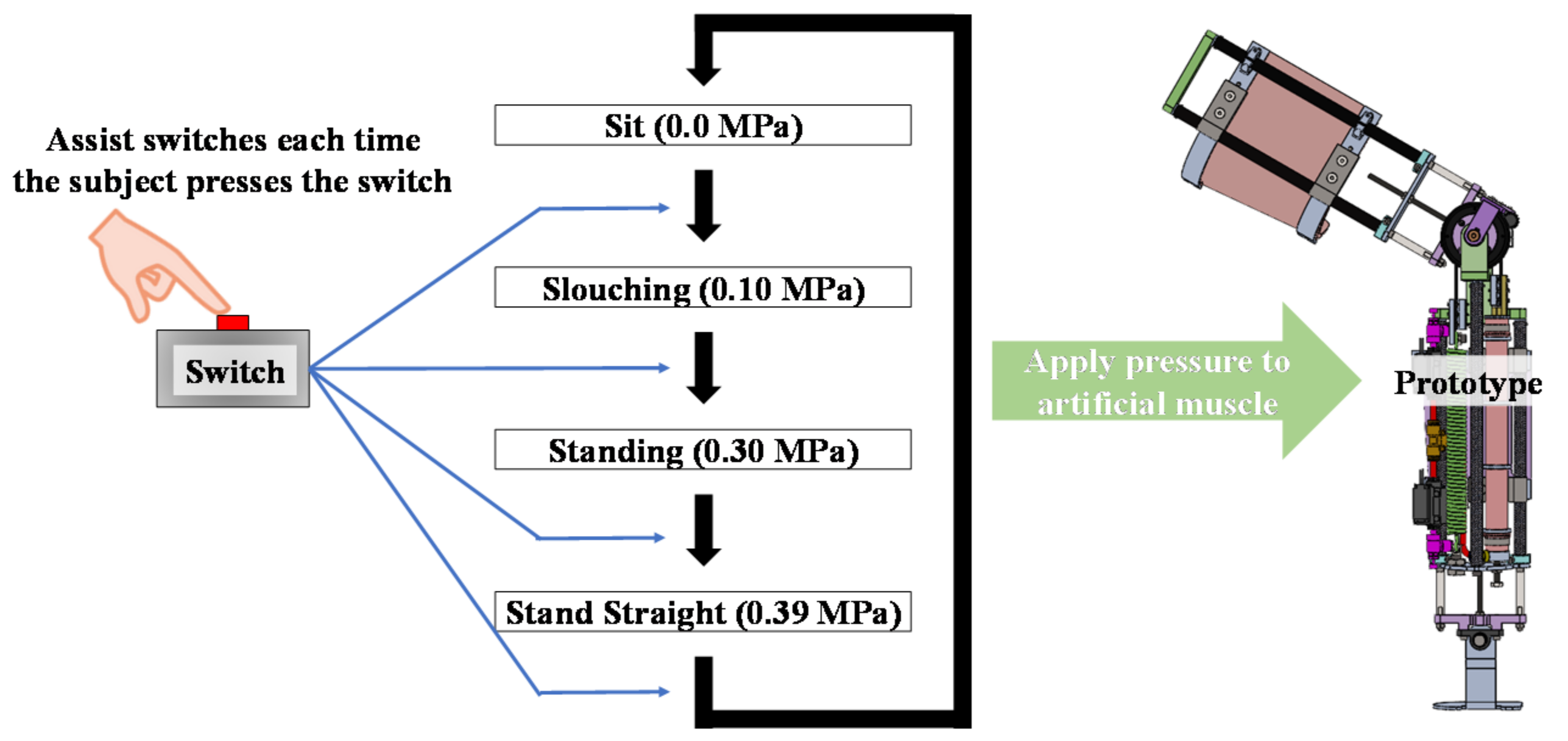
4.2.4. Operation Method
4.2.5. Experimental Method
4.2.6. Analysis Method
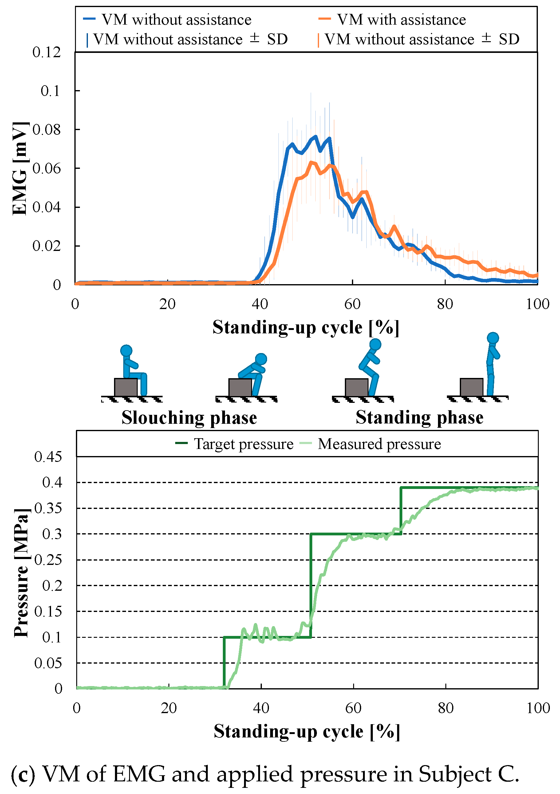
4.2.7. Result and Discussion
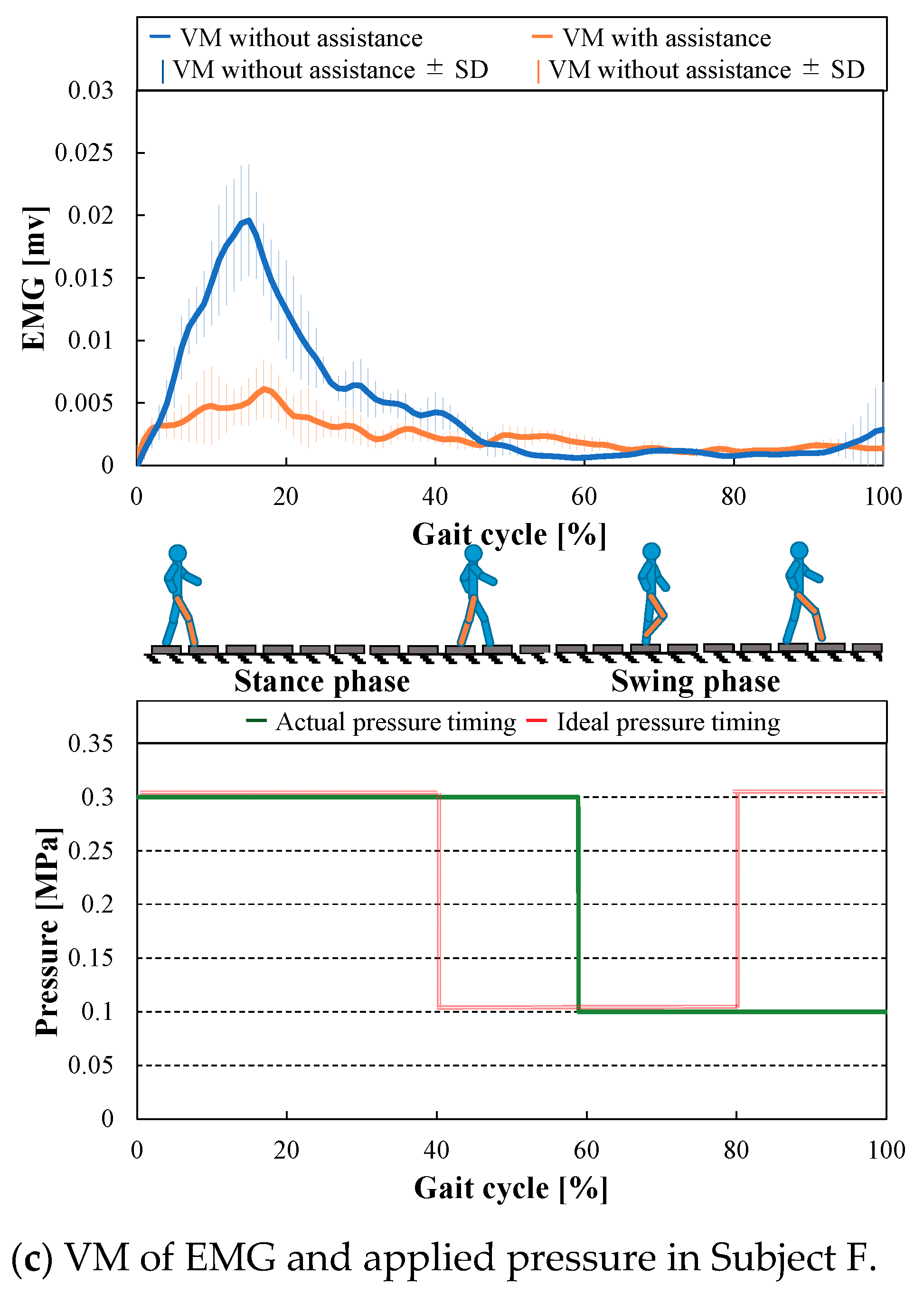
4.3. Assist of Gait Motion
4.3.1. Subjects
4.3.2. Experimental Environment
4.3.3. Assist Target Values
4.3.4. Operation Method
4.3.5. Experimental Method
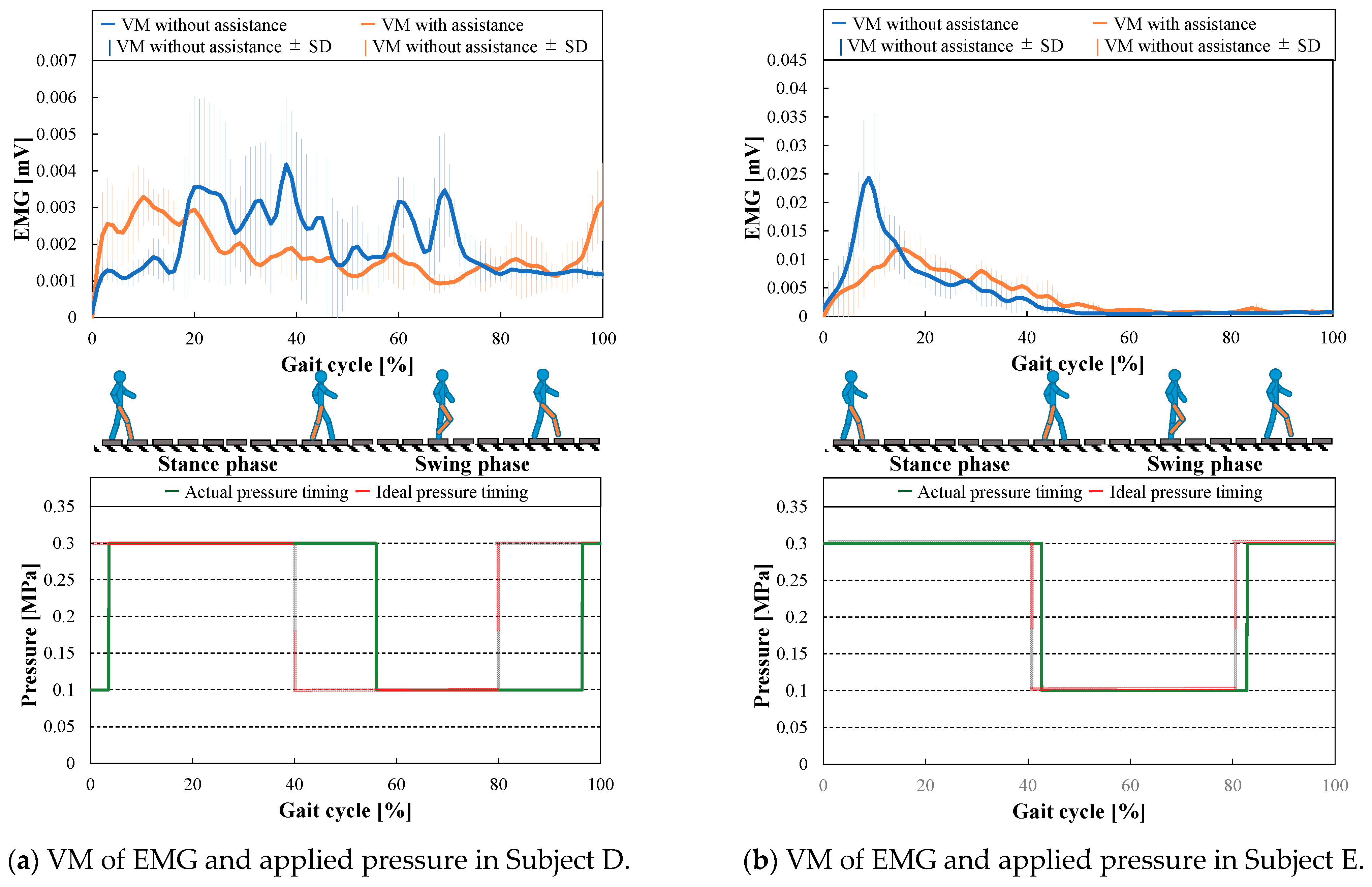
4.3.6. Result and Discussion
4.4. Summary of Assist Evaluation
5. Conclusions
Author Contributions
Funding
Institutional Review Board Statement
Informed Consent Statement
Data Availability Statement
Conflicts of Interest
Appendix A
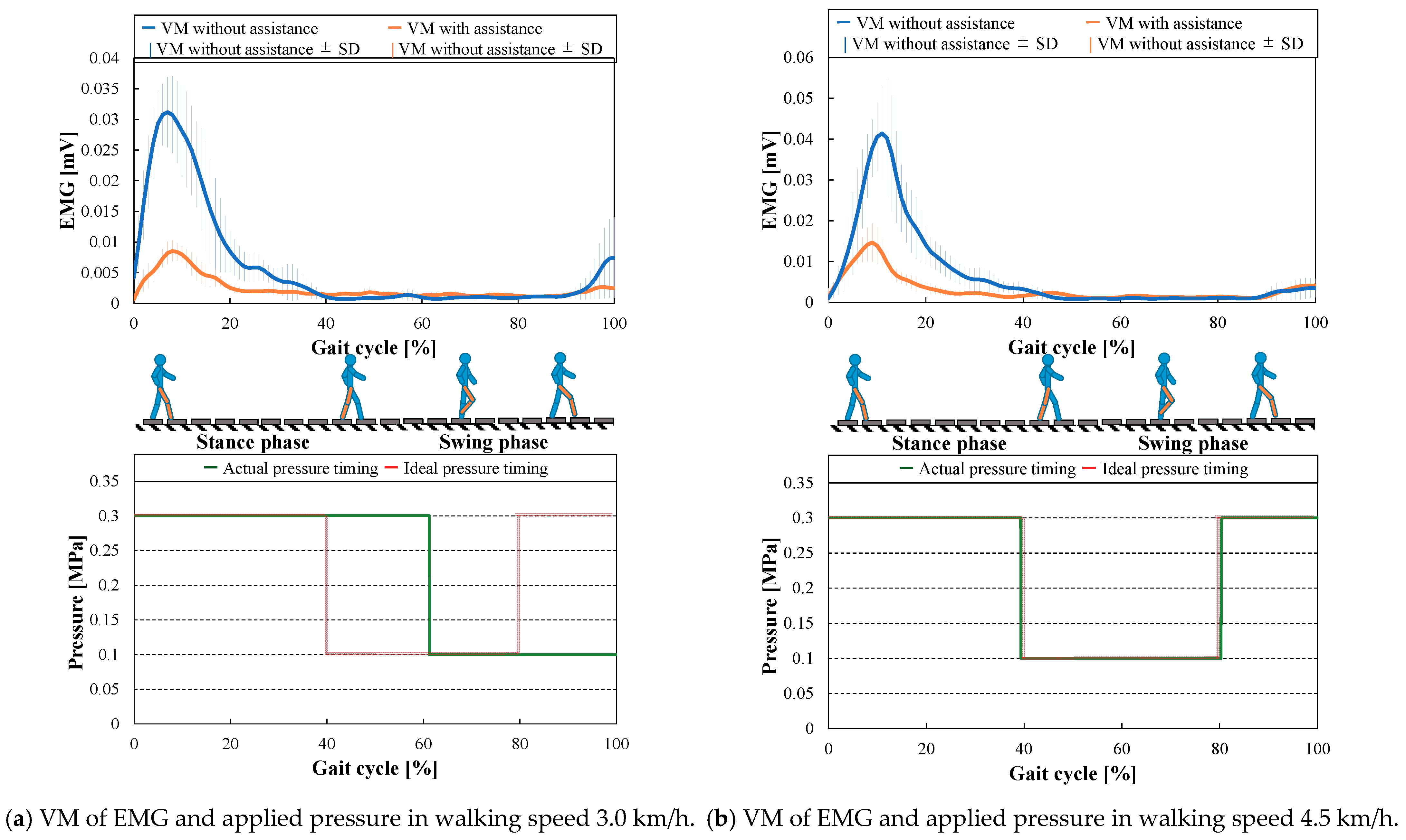
Appendix A.1. Effect of the Walking Speed
Appendix A.1.1. Experimental Information
Appendix A.1.2. Result and Discussion

References
- Evans, W. Functional and Metabolic Consequences of Sarcopenia. J. Nutr. 1997, 127, 988S–1003S. [Google Scholar]
- Humphries, B.; McBride, T.T.; Newton, R.U.; Marshal, S.; Bronks, R.; McBride, J.; Hakkien, K.; Kraemer, W.J. The Relationship Between Dynamic, Isokinetic and Isometric Strength and Bone Mineral Density in a Population of 45 to 65 Years Old Women. J. Sci. Med. Sport 1999, 2, 364–374. [Google Scholar] [CrossRef]
- Goodpaster, B.H.; Carison, C.L.; Visser, M.; Kelly, D.E.; Scherzinger, A.; Harris, T.B.; Stamm, E.; Newman, A.B. Attenuation of skeletal muscle and strength in the elderly: The Health ABC Study. J. Appl. Physiol. 2001, 90, 2157–2165. [Google Scholar] [CrossRef] [PubMed]
- Azegami, M.; Ohira, M.; Miyoshi, K.; Kobayashi, C.; Hongo, M.; Yanagihara, R.; Sadoyama, T. Effect of single and multi-joint lower extremity muscle strength on the functional capacity and ADL_IADL status in Japanese community-dwelling older adults. Nurs. Health Sci. 2007, 9, 168–176. [Google Scholar] [CrossRef] [PubMed]
- Bize, R.; Johnson, J.A.; Plotnikoff, R.C. Physical activity level and health-related quality of life in the general adult population: A systematic review. Prev. Med. 2007, 45, 401–415. [Google Scholar] [CrossRef] [PubMed]
- Hayashi, T.; Kawamoto, H.; Sankai, Y. Control Method of Robot Suit HAL working as Operator’s Muscle using Biological and Dynamical Information. In Proceedings of the IEEE/RSJ International Conference on Intelligent Robots and Systems (IROS), Edmonton, AB, Canada, 2–6 August 2005; pp. 3063–3068. [Google Scholar]
- Muramatsu, Y.; Umehara, H.; Kobayashi, H. Improvement and Quantitative Performance Estimation of the Back Support Muscle Suit. In Proceedings of the 35th International Conference of the IEEE Engineering Medicine and Biology Society (EMBS), Osaka, Japan, 3–7 July 2013; pp. 2844–2849. [Google Scholar]
- Sasaki, D.; Noritsugu, T.; Takaiwa, M. Development of Pneumatic Lower Limb Power Assist Wear driven with Wearable Air Supply System. In Proceedings of the IEEE/RSJ International Conference on Intelligent Robots and Systems (IROS), Tokyo, Japan, 3–7 November 2013; pp. 4440–4445. [Google Scholar]
- Okui, M.; Iikawa, S.; Yamada, Y.; Nakamura, T. Variable viscoelastic joint system and its application to exoskeleton. In Proceedings of the 2017 IEEE/RSJ International Conference on Intelligent Robots and Systems (IROS), Vancouver, BC, Canada, 24–28 September 2017; pp. 3897–3902. [Google Scholar]
- ReWalk More Than Walking, ReWalk Robotics, Inc. Available online: http://rewalk.com/ (accessed on 1 March 2020).
- ATOUN, ATOUN Inc. Available online: http://atoun.co.jp/ (accessed on 1 March 2020).
- Hogan, N. Adaptive Control of Mechanical Impedance by Coactivation of Antagonist Muscles. IEEE Trans. Autom. Control 1984, AC-29, 681–690. [Google Scholar] [CrossRef] [Green Version]
- Sakaguchi, S.; Venture, G.; Coste, C.A.; Havashibe, M. Active joint viscoelasticity estimation of the human knee using FES. In Proceedings of the 4th IEEE RAS & EMBS International Conference on Biomedical Robotics and Biomechatronics, Rome, Italy, 24–27 June 2012; pp. 1644–1649. [Google Scholar]
- Okui, M.; Iikawa, S.; Yamada, Y.; Nakamura, T. Fundamental characteristic of novel actuation system with variable viscoelastic joints and MR clutches for human assistance. J. Intell. Mater. Syst. Struct. 2017, 29, 1045389X1770521. [Google Scholar] [CrossRef] [Green Version]
- Ivanenko, Y.P.; Poppele, R.E.; Lacquaniti, F. Five basic muscle activation patterns account for muscle activity during human locomotion. J. Physiol. 2004, 556, 267–282. [Google Scholar] [CrossRef] [PubMed]
- Wada, T.; Sano, H.; Sekimoto, M. Analysis of Inertial Motion in Swing Phase of Human Gait and Its Application to Motion Generation of Transfemoral Prosthesis. In Proceedings of the IEEE/RSJ International Conference on Intelligent Robots and Systems (IROS), Chicago, IL, USA, 14–18 September 2014; pp. 2075–2080. [Google Scholar]
- Ernesto, A.V.; Hugh, H. Agonist-antagonist active knee prosthesis: A preliminary study in level-ground walking. J. Rehabil. Res. Dev. 2009, 46, 361–373. [Google Scholar]
- Kimura, S.; Suzuki, R.; Kashima, M.; Okui, M.; Nishihama, R.; Nakamura, T. Assistive method that controls joint stiffness and antagonized angle based on human joint stiffness characteristics and its application to an exoskeleton. In Proceedings of the 19th International Conference on Advanced Robotics (ICAR), Belo Horizonte, Brazil, 2–6 December 2019. [Google Scholar]
- Kimura, S.; Suzuki, R.; Kashima, M.; Okui, M.; Nishihama, R.; Nakamura, T. Assistance by Controlling the Stiffness and Antagonized Angle of One side Spring Antagonized Joint and Application to Standing up and Gait motion. In Proceedings of the ROBOMECH 2019, Hiroshima, Japan, 5–8 June 2019. [Google Scholar]
- Kimura, S.; Machida, K.; Suzuki, R.; Kashima, M.; Okui, M.; Nishihama, R.; Nakamura, T. Evaluation of basic characteristic of variable stiffness assist suit based on the one-sided spring antagonized joint. In Proceedings of the ROBOMECH 2020, Kanazawa, Japan, 27–30 May 2020. [Google Scholar]
- Nakamura, T. Experimental Comparisons between McKibben type Artificial Muscles and Staraight Fiber Type Artificial Muscles. In Proceedings of the SPIE International Conference Smart Structures, Devices and Systems III, Adelaide, Australia, 10–13 December 2006; p. 641424. [Google Scholar]
- Tomori, H.; Nakamura, T. Theoretical comparison of mckibben-type artificial muscle and novel straight-fiber-type artificial muscle. Int. J. Autom. Technol. 2011, 5, 544–550. [Google Scholar] [CrossRef]
- Suzuki, R.; Okui, M.; Iikawa, S.; Yamada, Y.; Nakamura, T. Novel Feedforward Controller for Straight-Fiber-Type Artificial Muscle Based on an Experimental Identification Model. In Proceedings of the First IEEE-RAS International Conference on Soft Robotics (RoboSoft), Livorno, Italy, 24–28 April 2018; p. WeBT.3. [Google Scholar]
- Hanten, W.P.; Schulthies, S.S. Exercise Effect on Electromyographic Activity of the Vastus Medialis Oblique and Vastus Lateralis Muscles. Phys. Ther. 1990, 70, 561–565. [Google Scholar] [CrossRef] [PubMed] [Green Version]
- Takahashi, K.; Sato, Y.; Suzuki, M.; Murakami, K.; Onobe, J.; Fujisawa, H. Lower Limb Muscle Activities and Cardiopulmonary Function during Treadmill Walking with Partial Body Weight Support. J. Phys. Ther. Sci. 2011, 26, 83–88. [Google Scholar]
- Oka, H.; Mori, E.; Kumamoto, M. Electromyographic Study of Lower Limb Muscle Activity Patterns During Normal Walking. J. Kansai Med. Univ. 1984, 36, 131–151. [Google Scholar] [CrossRef] [Green Version]
- Kimura, S.; Suzuki, R.; Machida, K.; Nishihama, R.; Okui, M.; Nakamura, T. Proposal of Motion Judgment Algorithm Based on Joint Angle of Variable Elastic Assist Suit with High Back Drivability. J. Robot. Mechatron. 2020, 32, 863–875. [Google Scholar] [CrossRef]


| c2 | −67.5 × 10⁻³ | r | 22.0 × 10⁻³ [m] |
| d2 | 3.60 × 10⁻³ | θa | 0 [deg] |
| f2 | 1.81 × 10³ | P2 | 0 ~ 0.39 [MPa] |
| g2 | 273 | k1 | 4900 [N/m] |
| Applied Pressure [MPa] | Stiffness [N m/deg] | Antagonized Angle [deg] |
|---|---|---|
| 0.10 | 0.0831 | 67.0 |
| 0.15 | 0.112 | 37.4 |
| 0.20 | 0.140 | 19.8 |
| 0.25 | 0.169 | 8.2 |
| 0.30 | 0.197 | 0.0 |
| Subject | A | B | C |
|---|---|---|---|
| Age | 22 | 24 | 22 |
| Height [m] | 1.80 | 1.75 | 1.74 |
| Weight [kg] | 90 | 70 | 54 |
| Assist Motion | Standing-up Motion | |
|---|---|---|
| Phase | Slouching | Standing |
| Assist Type | Passive | Active |
| Criteria for joint stiffness [N m/deg] | 11.1 | 0.625 |
| Criteria for antagonized angle [deg] | 92 | 4.73 |
| Assist rate [%] | 10 | 30 |
| Target joint stiffness [N m/deg] | 1.11 | 0.188 |
| Target antagonized angle [deg] | 92 | 4.73 |
| Applied pressure [MPa] | 0.10 | 0.30 |
| Joint stiffness of the device [N m/deg] | 0.0831 | 0.197 |
| Antagonized angle of the device [deg] | 67 | 0 |
| Subject | D | E | F |
|---|---|---|---|
| Age | 23 | 22 | 23 |
| Height [m] | 1.74 | 1.75 | 1.8 |
| Weight [kg] | 54 | 64 | 80 |
| Assist Motion | Gait Motion | |
|---|---|---|
| Phase | Stance | Swing |
| Assist Type | Passive | Active |
| Criteria for joint stiffness [N m/deg] | 3.86 | 0.329 |
| Criteria for antagonized angle [deg] | 13.4 | 63.2 |
| Assist rate [%] | 10 | 30 |
| Target joint stiffness [N m/deg] | 0.386 | 0.0987 |
| Target antagonized angle [deg] | 13.4 | 63.2 |
| Applied pressure [MPa] | 0.30 | 0.10 |
| Joint stiffness of the device [N m/deg] | 0.197 | 0.0831 |
| Antagonized angle of the device [deg] | 0 | 67 |
Publisher’s Note: MDPI stays neutral with regard to jurisdictional claims in published maps and institutional affiliations. |
© 2021 by the authors. Licensee MDPI, Basel, Switzerland. This article is an open access article distributed under the terms and conditions of the Creative Commons Attribution (CC BY) license (http://creativecommons.org/licenses/by/4.0/).
Share and Cite
Kimura, S.; Suzuki, R.; Machida, K.; Kashima, M.; Okui, M.; Nishihama, R.; Nakamura, T. Development of an Exoskeleton-Type Assist Suit Utilizing Variable Stiffness Control Devices Based on Human Joint Characteristics. Actuators 2021, 10, 17. https://0-doi-org.brum.beds.ac.uk/10.3390/act10010017
Kimura S, Suzuki R, Machida K, Kashima M, Okui M, Nishihama R, Nakamura T. Development of an Exoskeleton-Type Assist Suit Utilizing Variable Stiffness Control Devices Based on Human Joint Characteristics. Actuators. 2021; 10(1):17. https://0-doi-org.brum.beds.ac.uk/10.3390/act10010017
Chicago/Turabian StyleKimura, Seigo, Ryuji Suzuki, Katsuki Machida, Masashi Kashima, Manabu Okui, Rie Nishihama, and Taro Nakamura. 2021. "Development of an Exoskeleton-Type Assist Suit Utilizing Variable Stiffness Control Devices Based on Human Joint Characteristics" Actuators 10, no. 1: 17. https://0-doi-org.brum.beds.ac.uk/10.3390/act10010017