
Universal Control of Permanent Magnet Synchronous Motors with Uncertain Dynamics


Intelligent Robotic and Energy Systems Research Group, Faculty of Engineering and Design, Carleton University, Ottawa, ON K1S 5B6, Canada
*
Author to whom correspondence should be addressed.
Actuators 2021, 10(3), 49; https://0-doi-org.brum.beds.ac.uk/10.3390/act10030049
Submission received: 27 January 2021
/
Revised: 19 February 2021
/
Accepted: 26 February 2021
/
Published: 3 March 2021
(This article belongs to the Section Actuators for Land Transport)
Abstract
:This paper focuses on the universal control design of permanent magnet synchronous motors (PMSMs) with uncertain system dynamics. In vector control, classical proportional-integral (PI) controllers are used to control d-q axis currents and speed of the PMSM. This paper uses two control methods: conventional field-oriented vector control and simplified control. First, all the control gains are determined for numerous PMSMs with various power ratings using an empirical study and generalized mathematical expressions are derived for each of the gains. Then, these expressions are used for automatic gain calculation for various PMSMs with a wide power-rating range. In vector control, the control gains are determined using only the motor power ratings. In the simplified control, generalized control gain expressions are obtained using the number of pole pairs and the flux linkage. Compared to the vector control, the simplified control method provides much simpler generalized mathematical expressions. Validation is carried out in MATLAB/Simulink environment using various PMSMs from 0.2 HP to 10 HP, and results show accurate tracking of reference speed and d-q axis reference currents. Thus, the proposed gain scheduling approach is effective and can be used for self-commissioning motor drives.
1. Introduction
Permanent magnet synchronous motors (PMSMs) are used in various industrial applications due to their many advantages over induction motors like efficiency, torque-to-current ratio and power density [1]. The d-q axis current control has a vital role to play in a vector controlled PMSM to achieve better system dynamic performance [2]. Current control is also important as it has a direct effect on torque control [3]. The use of proportional-integral (PI) controllers is the most common approach in the implementation of d-q axis currents and speed control loops due to their simplicity [2]. Several tuning methods for obtaining the PI control gains have been proposed in recent years [1,4,5,6,7,8,9]. Trial-and-error and Ziegler–Nichols are some of the most commonly used tuning methods for controlling PMSM [1].
It is difficult to obtain good performance using linear control algorithms, as the PMSM is a non-linear system that is subject to parameter variations and multiple coupled states [10]. Many non-linear control methods have come to light due to the recent developments in motor control techniques [10]. In [11], a boundary layer integral sliding mode controller is designed based on a quasi-linearized and decoupled model considering the effect of parameter variations. In [12], the non-linearity of a voltage source inverter (VSI) is considered to propose an adaptive super-twisting algorithm based sliding mode observer (STA-SMO) for the surface-mounted PMSMs. To achieve better accuracy of the PMSM model, the voltage distortion due to VSI non-linearity is compensated online [12]. A simple adaptive disturbance observer is used in [13] with a robust controller, which uses an adaptive element in the reference-voltage-generation stage using the feedforward control. Depending on the various operating conditions of the PMSM, the adaptive element is selected as an uncertainty function which changes accordingly [13]. In [14], a robust fractional order proportional-plus-differential controller is proposed, which varies with an acted function. The parameters of the acted function are determined based on a fuzzy logic inference algorithm [14]. In [15], a non-linear internal model based output feedback controller is used for the position tracking for PMSM drive. In the last few years, better control techniques incorporating predictive current controllers [16,17,18] are receiving attention in the PMSM drive domain. A discrete-time robust predictive current controller is proposed in [16], based on the dead-beat structure. However, unmodeled dynamics and parametric uncertainties are drawbacks of the dead-beat control [16]. In [17], the current control is achieved while satisfying the real-time and physical constraints of PMSM drives by obtaining fast transient current response adjusting the stator voltages. A five-phase PMSM is controlled using the proposed finite control set model predictive current control (FCS-MPCC) in [18]. At low speed, the sensor-less control of PMSM can be accomplished by a signal injection method in [19], which ideally requires only one voltage vector for position estimation. In [20], a control Lyapunov function over a discrete set of realizable inputs generates the input switching sequences for the PMSM control system. Each input has its own stabilizing effect on the control system [20], upon which the switching decisions can be made for the input selection process. In [21], a predictive functional control (PFC) technique is proposed for the control design of the speed loop. But the PFC method does not give proper results in the case of strong disturbances, due to which an extended state observer (ESO) is introduced, which adds a feedforward compensation item based on the estimated disturbances [21]. In [22], the control of a PMSM driven by a matrix converter is accomplished using a new speed finite control set model predictive control algorithm that uses a single control law instead of the cascaded control scheme.
In recent years, artificial intelligence techniques such as fuzzy logic and artificial neural networks are gaining more attention in the field of PMSM control due to their many advantages over the conventional methods. A fuzzy PI-type current controller is used in [23], which stabilizes the decoupled dynamics and ensures the stability of the PMSM. But this approach has some problems dealing with the time-varying uncertainties [23]. In [24], a speed control integrated circuit (IC) is proposed under a system-on-a-programmable-chip (SoPC) environment for the PMSM drive. Here, the external load effect and dynamic uncertainty in the speed loop of a PMSM is considered for the operation of an adaptive fuzzy controller [24]. A decentralized adaptive fuzzy controller for the PMSM drive is used in [25], based on the type-2 fuzzy logic systems and adaptive control theory. An artificial neural network (ANN)-based real-time adaptive controller is proposed in [26], which initially generates estimated coefficients using an offline training method. Then, to update the ANN, an online training is executed using the dynamic back-propagation with the Levenburg–Marquardt algorithm [26]. In [27], the unknown and non-linear functions of the PMSM are approximated using neural-networks (NNs) and an adaptive dynamic surface control (DSC) is proposed. A speed control strategy for a six-phase PMSM is proposed in [28] using a robust adaptive back-stepping sliding mode control (ABSMC) with recurrent wavelet fuzzy neural network (RWFNN) considering the load disturbances and parameter variations. In [29,30], a recurrent fuzzy neural cerebellar model articulation network (RFNCMAN) is considered for a six-phase PMSM position servo drive system, which is also equipped with a fault tolerant control scheme.
Apart from the commonly used vector control, one other control strategy known as the direct torque control (DTC) is also explored by many researchers. In [31], the reduction of torque ripple and stator flux ripple is achieved using the proposed duty ratio modulated direct torque control technique. In [32], the torque and flux ripple reduction can be observed while improving the dynamic response of the classical DTC technique with the help of a new predictive DTC strategy. In [33], the internal model principle and variable structure control (VSC) approach are combined to obtain a new hybrid control model, and a direct instantaneous torque control scheme is proposed for a direct drive (DD) PMSM.
Despite the many theoretical advances achieved in PMSM control, more research is needed in the intelligent learning-based control techniques and better experimental validation is also required for the most favorable control methods. Unlike various control methods reported in the literature, this paper uses a classical PI control approach due to its design simplicity and good performance. In [34], an altitude control algorithm is presented for a quadcopter using the advantage of conventional proportional-integral derivative (PID) control technique by resolving some of its drawbacks. In [35], the stability of an autonomous quad-rotor is achieved using the PID control strategy. An autonomous quadcopter robust landing algorithm is proposed in [36] to accomplish precision landing task. In [37], temperature control of a diffusion furnace is achieved using a PID controller tuned with the help of a frequency loop-shaping method. PID controller is used for stabilization of modern voltage regulator system in [38], which can help the technicians and engineers in better understanding of digital controller tuning. Thus, several control methods are available but the PID control approach is widely used in a variety of applications across the world [34]. In [39], an efficient PID controller gain auto-tuning method is proposed through reinforcement learning neural networks for a complex system like a multicopter. The neural network is trained and updated every time until it chooses the best action to find the controller gains [39]. Various auto-tuning techniques are also presented in [40,41,42] which need little prior system information and are robust to noise. Although the aforementioned control methods achieve good performance, they use very complex control algorithms which increases the computational burden. The proposed method to find the PI controller gains uses simple mathematical expressions which make it more suitable for low-cost real-time implementation. Moreover, compared to the aforementioned control methods, the proposed technique can be applied to multi-power range motor types.
The main objective of this paper is to automatically obtain the PI control gains by only using few motor parameters like its power rating, number of pole pairs and magnetic flux linkage. Accurate tracking of d-q axis currents and speed of the PMSM is observed with the help of a self-tuned PI controller. Two control techniques are discussed in this paper: vector control and a proposed simplified control. In vector control, the PI controller gains are calculated in terms of the motor power ratings using a set of non-linear equations, while, in simplified control, the product of number of pole pairs and magnetic flux linkage () is used in a set of linear equations for determining the control gains. A synopsis of the entire procedure for deriving the appropriate mathematical expressions is as follows:
- Four suitable PMSMs are used to obtain the PI controller gains through trial-and-error approach.
- A curve of the control gains is plotted against the motor power ratings or product values for each of the PI controller gain constants according to the control method used.
- For a single PMSM, two values of lower and upper limits for a control gain are obtained. Thus, all the values lying between these two limits are valid.
- An average curve lying between these two limits is generated through an empirical study, and a generalized mathematical expression is obtained.
- Afterwards, to validate this proposed tuning method, four new PMSMs are simulated in MATLAB/Simulink environment using these generalized mathematical expressions, and the results show accurate tracking of the currents and the speed.
It is observed that simpler generalized mathematical equations are obtained in simplified control compared to the vector control for each of the PI controller gains. However, vector control gives better accuracy in terms of reduced speed and d-q axis current errors compared to the simplified control. Unlike the aforementioned techniques discussed before, the proposed tuning methods do not use complex control algorithms and are much simpler and convenient to apply. The proposed approach also requires very minimal information on the motor’s dynamics. Due to the use of simple PI controllers, this control algorithm is very cost effective compared to most of the other techniques, especially machine learning ones. Many industrial and practical applications involve the use of multiple PMSMs with different power ratings, where both these proposed methods can provide a hassle-free way to efficiently tune those motors.
This paper is organized as follows: The description of mathematical modeling of PMSM is given in Section 2. In Section 3, the control design of vector control and simplified control are mentioned in detail. Section 4 provides the testing of both the proposed tuning strategies by obtaining some generalized mathematical expressions for gain calculation. The verification of the proposed control methods using the MATLAB/Simulink software is given in Section 5. Finally, Section 6 concludes this paper.
2. Mathematical Modeling of Permanent Magnet Synchronous Motor (PMSM)
The PMSM model can be described in the form of the following nonlinear mathematical equations in the d-q reference frame [27]:
Here, for interior permanent magnet synchronous motor and for surface-mounted permanent magnet synchronous motor. The conventional field-oriented vector control is based on the Park transformation. Equation (1) derives the rotor speed using the rate of change of rotor position. The electromagnetic torque balance equation is represented by Equation (2). The stator voltage equations can be derived from Equations (3) and (4) with the help of the usual motor sign conventions. More details regarding the PMSM mathematical model can be found in [20]. These mathematical equations form the basis of the PMSM control strategy which is discussed in the next section.
3. Control Design
3.1. Vector Control
The conventional field-oriented vector control strategy uses the Park transformation, as shown in Figure 1. The stator voltage equations in the d-q reference frame are obtained from Equations (3) and (4). A feedback signal of rotor speed is compared with the reference speed, which determines the q-axis current reference using the outer loop PI controller driven by the speed error [19]. The current loop control technique is developed using the dynamic Equations (3) and (4). The current references (torque reference) and (flux reference) are compared with the and components, respectively. The two PI controllers for d-q axis current control give the voltage signals in the d-q reference frame [19]. The controller gains of all the three standard PI controllers used here can be represented as given in Equations (5)–(7). The second proposed strategy called the simplified control is explained in Section 3.2 which uses only two PI controllers driven by the speed the d-axis current error. Both these proposed control techniques aim to determine the PI controller gains in a simple way using some motor parameters. The rotor position information is required to convert the d-q voltage commands into and components, which are the inputs of the space vector pulse width modulation (SVPWM) [19]. The 3-phase inverter is driven by the outputs of the SVPWM block. Two motor phase currents are measured and are fed to the Clarke transformation module, giving the outputs and . These two components of the current act as the inputs to the Park transformation block which gives the currents in the d-q rotating reference frame.
3.2. Simplified Control
The modeling equations of PMSM play a vital role in its control strategy and one such equation is used for the working of the simplified control method. The simplified control is an attempt to make the vector control scheme less complicated by eliminating the need for cascaded PI controllers. The only difference between the vector control and simplified control is the way of calculating the voltage component . Considering Equation (4), it can be seen that the value of mainly depends on the product of and , as the rest of the terms hold insignificant values due to low , and . As shown in Figure 2, the outer loop PI controller uses the speed error to generate the output of q-axis voltage component This strategy nullifies the need for the second PI controller driven by the current error to calculate . In the previously mentioned vector control method, any variation in torque affects the speed and iq current which is controlled by the two outer loop PI controllers while, in the simplified control technique, this task is accomplished by only one PI controller. Thus, if any over current situation arises in the industrial environment, it can be maintained within an acceptable range with the help of the given one outer loop PI controller. Hence, in this method only two PI controllers are used in total which are driven by the speed and d-axis current errors. The outputs of these two PI controllers can be represented by Equations (8) and (9) to achieve optimal control.
4. Testing for Proposed Universal Control Strategies
4.1. Testing Procedure
A total of eight motors are used for the determination and validation of this proposed control scheme. These eight motors are represented as M1, M2, M3, …, M8 in Table 1, consisting of both the interior and surface mounted types of PMSMs. In this paper, PMSMs of up to 7.5 kW power ratings are used, while further analysis is required for motors with higher ratings. Motors M1, M4, M6 and M8 are used for the generalization of this control technique, while the remaining four motors are used for verification purposes. The testing scenario used in MATLAB/Simulink for the four generalization motors is described in detail as follows: The total test time is 60 s and the desired speed signal is taken as a step response of a critically damped second-order system. First, at 5 s, the speed increases to 500 rpm with no load. Once at a steady state, full load is applied, and the speed is increased again to the motor’s rated speed of 1500 rpm. Then, the speed goes back to 500 rpm before the load is suddenly released and the motor is brought to the full stop.
4.2. Proposed Universal Control Algorithm
Considering the given topologies in Section 3, each motor needs to be tuned for six (vector control) or four (simplified control) control gains accordingly. The proportional gains for the speed and d-q axis current control are denoted by , and respectively, while the integral gains are represented as , and for the same. Motors M1, M4, M6, and M8 are tuned, and the lower and upper limits of each of the gains are found using an empirical study. The final values of the lower and upper limit gains for the speed and d-q axis currents are determined only if their relative percentage errors are almost zero at steady states and less than 1% during the transients. Perfect tracking of the reference value by the actual value with very little overshoots is also considered while calculating the final gain values.
Here, the main aim of this proposed control algorithm is to generate some mathematical equations which can calculate every controller gain just by using a system variable. This system variable is taken as the motor power rating for vector control, or the product value in the case of simplified control. First, for every motor, the lowest and highest possible values for each of the given control gains are plotted against the appropriate system variable. Then, in the next step, a generalized curve is to be formulated in the region enclosed between these values. For every control gain, a set of linear and non-linear curves are plotted in the bottom, center, and upper parts of the available region, and their corresponding mathematical expressions are formed. However, non-linear curves can not be plotted in the simplified control due to irregular nature of the highest gain points. Using the system variables of the four motors; M1, M4, M6, and M8, all these formulated equations are used to determine their respective control gains. These calculated gains are used for their respective motors and the control performance of their speed and d-q axis current tracking are observed. The main goal to draw these generalized curves in the lower, center, and higher regions is to determine which region gives the best performing control gains. In all the given linear and non-linear equations, the system variable is the only variable while the rest are some constant values. These constant values are altered after every trial by an empirical study until the gains calculated from these equations give the best control performance for all those PMSMs. It is found that the gains calculated using the non-linear curves give better accuracy compared to the linear ones. One of the curves from the three regions is finalized, whose calculated gains give the best accuracy in the speed and d-q axis current tracking. It can be seen that the generalized curves of the proportional gains are in the bottom region while those of the integral gains can be found in the upper part. The generalized equations can be applied to both the interior and surface-mounted types of PMSMs.
4.3. Derivation of Proportional-Integral (PI) Gain Equations for Vector Control Strategy
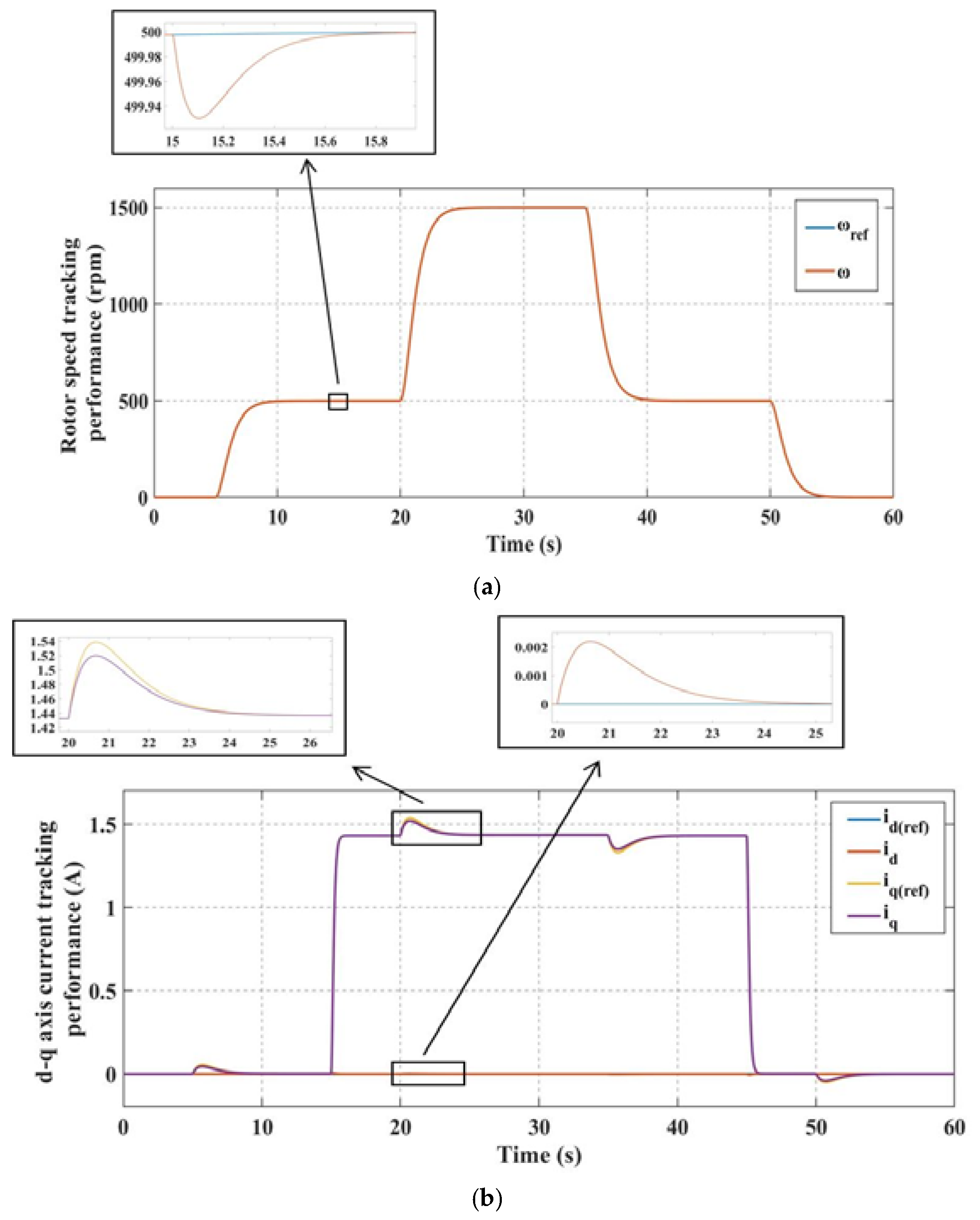
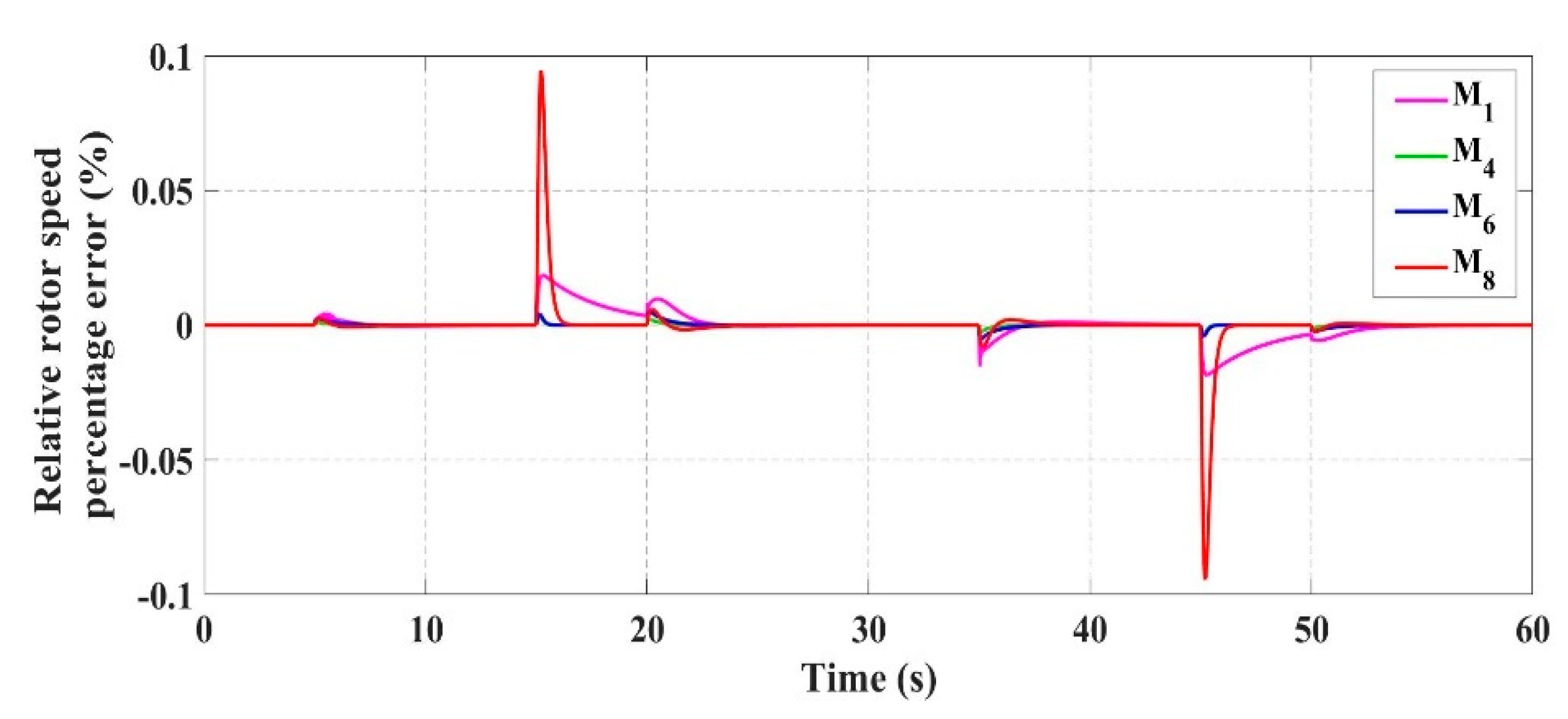
In the vector control, the outer loop PI controller operates using the speed error, and the two current loop PI controllers are driven to maintain the d-q axis reference currents. As mentioned in Section 4.2, four generalization motors are tuned, and the final gain values are determined if the speed and d-q axis current errors are within the acceptable range. To show the tracking accuracy of all the generalization motors, rotor speed percentage error (%) is presented in Figure 3. Here, it can be seen that tracking error increases with the size of the motor. Although motor M8 has the highest error among all the four PMSMs, its tracking error remains in an acceptable range. To analyze further its tracking performance, Figure 4 shows the speed and d-q axis currents. Figure 4 reveals a high tracking accuracy and a fast response when overcoming the applied load. The overshoot under such condition is negligible, i.e., 0.013%. It is worthwhile mentioning that less overshoot is observed for the other three PMSMs.
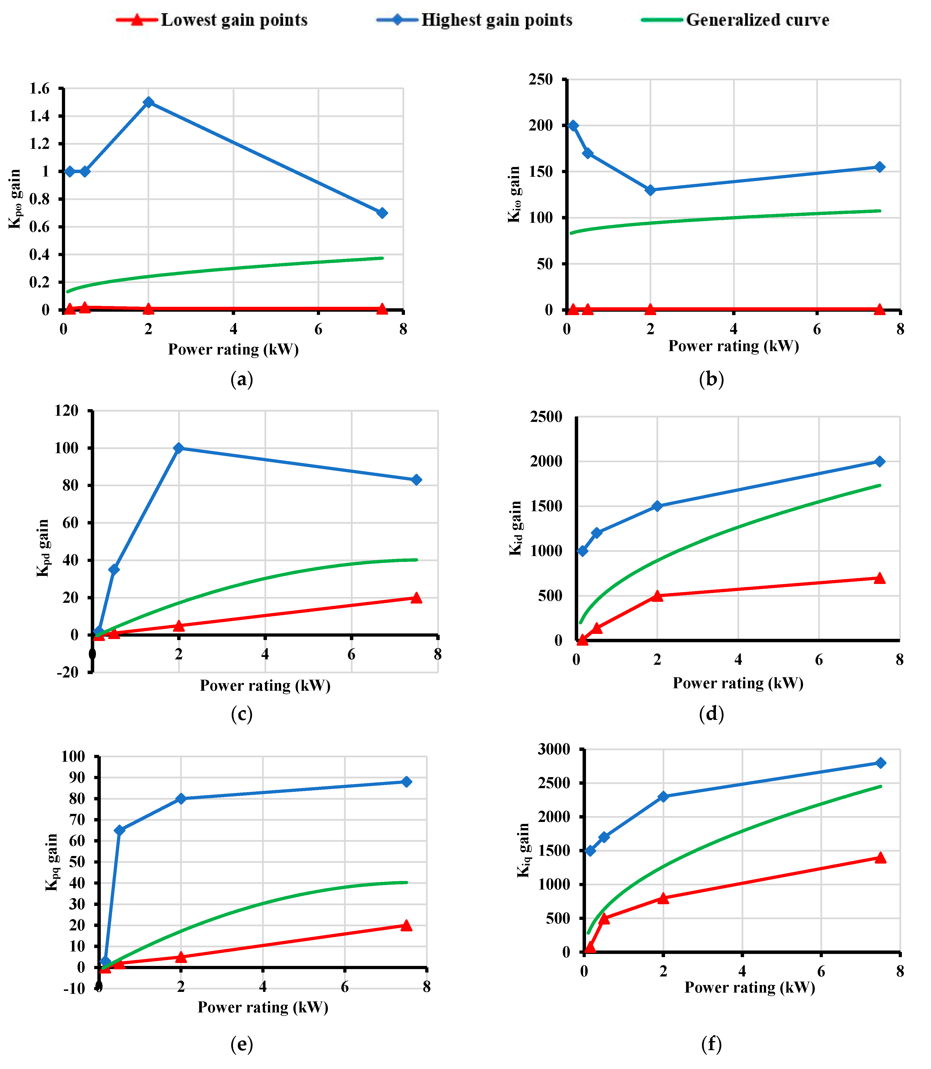
The power rating is the most easily available information on any motor’s nameplate, and thus, it is chosen as a variable to calculate every control gain in this control method. The lowest and highest possible values for each of the given control gains are plotted against the motor power ratings of the respective PMSMs. Then, a generalized curve is finalized in the enclosed region through an empirical study that can give the best possible accuracy. Figure 5 shows the plots of all the six control gains with respect to motor power ratings and their respective generalized curves. Physically, for the same power, some PMSMs may have different parameters which can influence the tuning process. Thus, both the proposed tuning strategies in this paper aim to control the PMSMs using minimum information of their system parameters. From Table 1, it can be observed that motor M6 with power rating of 2 kW has very high d-q axis inductance values compared to other PMSMs. Due to this, most of the curves of the highest gain points have mainly two types of slope for low and medium power ratings.
The non-linear generalized curve allows better precision in the tracking of the speed and d-q axis currents which is also justified by the non-linear nature of the PMSM’s dynamics. The non-linear mathematical expressions formulated from the generalized curves in Figure 5 can be represented as follows:
where p is the power rating in kW. It can be seen from Figure 5c,e that both these curves are almost identical. Thus, the same mathematical expression can be applied to both and gains as depicted in Equations (12) and (14). To verify the working of these mathematical expressions for PI control tuning, motors M2, M3, M5 and M7 are used for experimentation. The simulation results of these four motors in MATLAB/Simulink are discussed in Section 5.
4.4. Derivation of PI Gain Equations for Simplified Control Strategy
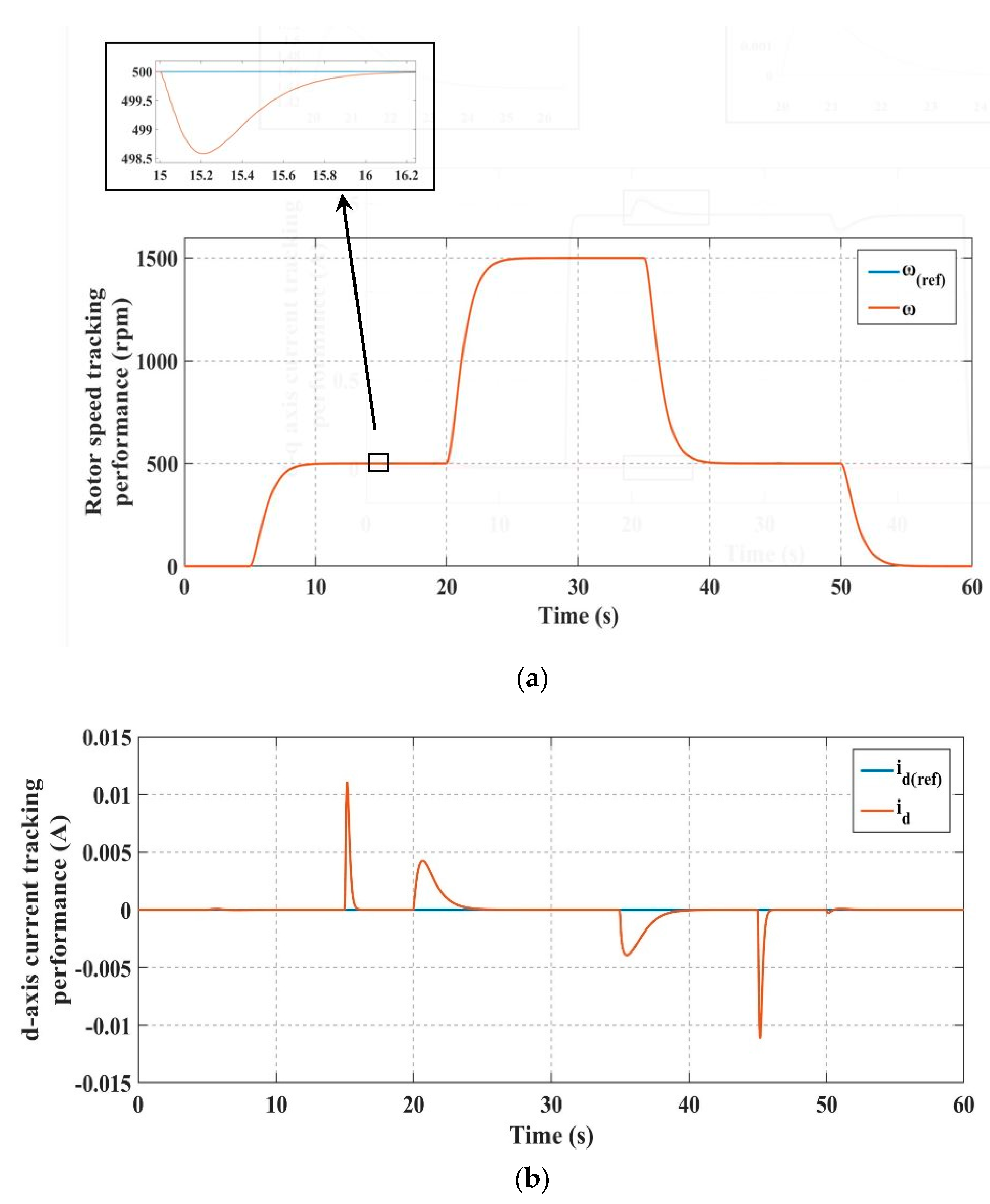
In the simplified control, the outer loop PI controller operates using the speed error, and the current loop PI controller is used to maintain the d-axis reference current. To establish a relationship between the product and control gains, all the PMSMs are arranged in the increasing order of product values. Thus, the motors are arranged in the order of M1, M2, M3, M4, M5, M8, M7 and M6 for the testing and validation of this control scheme. Voltage component is obtained as an output of the speed error PI controller instead of the inner loop PI controller, which uses the current error. As a result, the PI controller driven by the current error is eliminated. This makes the overall control structure less complex by getting rid of the cascaded controllers which are difficult to tune. Thus, four control gains are required to be tuned for the speed and current error PI controllers. Motors M1, M4, M8 and M6 are tuned using an empirical study, and their lowest and highest control gain points are plotted w.r.t the product values. To show the accuracy of those four generalization motors while finalizing their gain values, a plot of their relative rotor speed percentage errors (%) is mentioned in Figure 6. The speed and current tracking performance of motor M8 is shown in Figure 7 to verify its control precision. Although motor M8 yields the highest overshoot, i.e., 0.28%, it is still in a low range. The average values of the lower and higher limit gain points of the respective motors are used to achieve appropriate results.
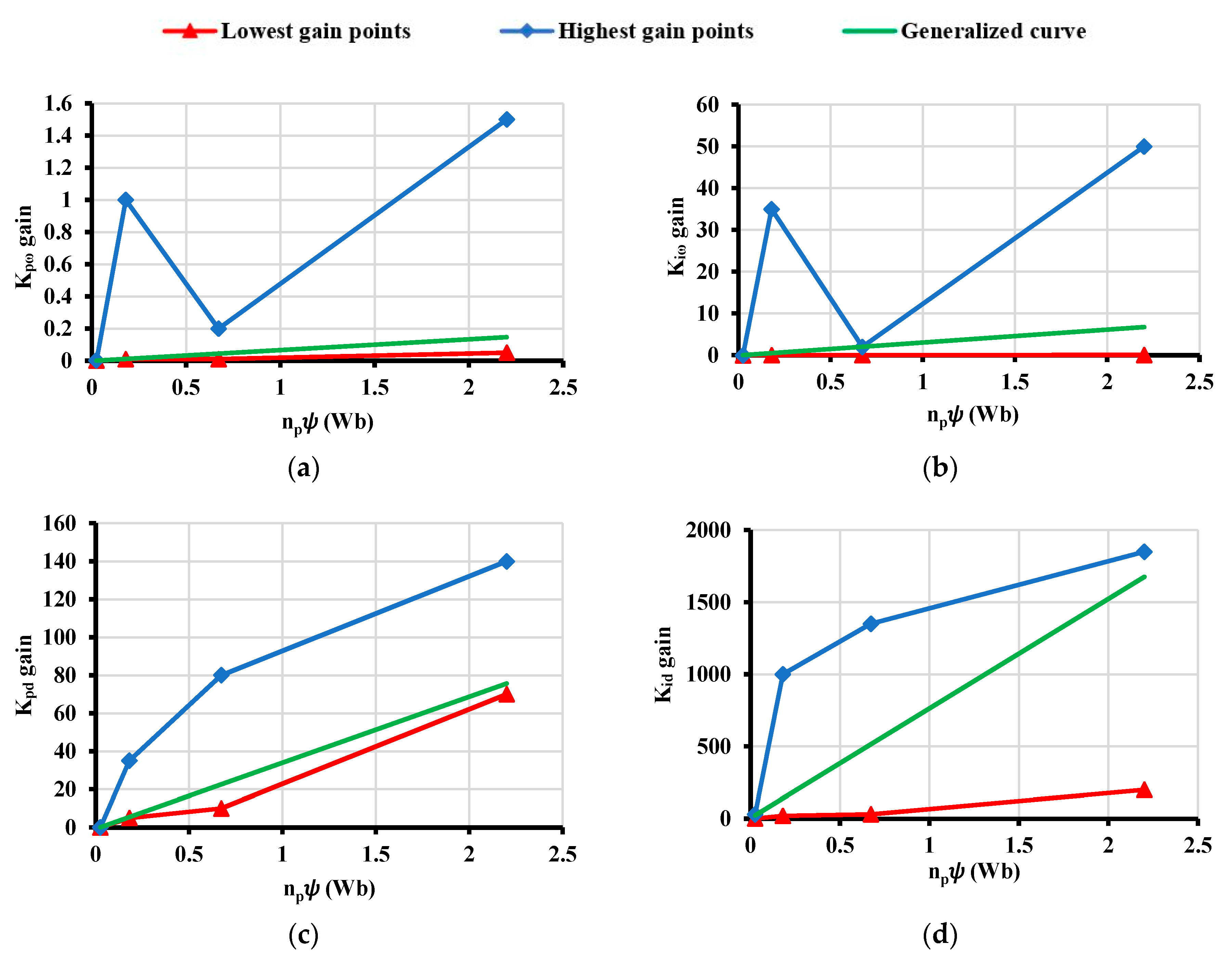
Unlike the vector control, a generalized non-linear curve cannot be formulated due to the irregular nature of the highest gain points. Thus, a linear curve is formed for every distinctive gain and further analyzed for its accuracy. The validation motors are used for determining the reliability of this control strategy which is discussed in Section 5. Figure 8 represents all the graphs of the control gains plotted against the product values in detail.
The generalized curves given in Figure 8 can be represented in the form of simple straight-line equations as follows:
To verify the functioning of these mathematical expressions for obtaining PI control gains, motors M2, M3, M5 and M7 are used and simulated in the MATLAB/Simulink software.
5. Controller Tuning Evaluation
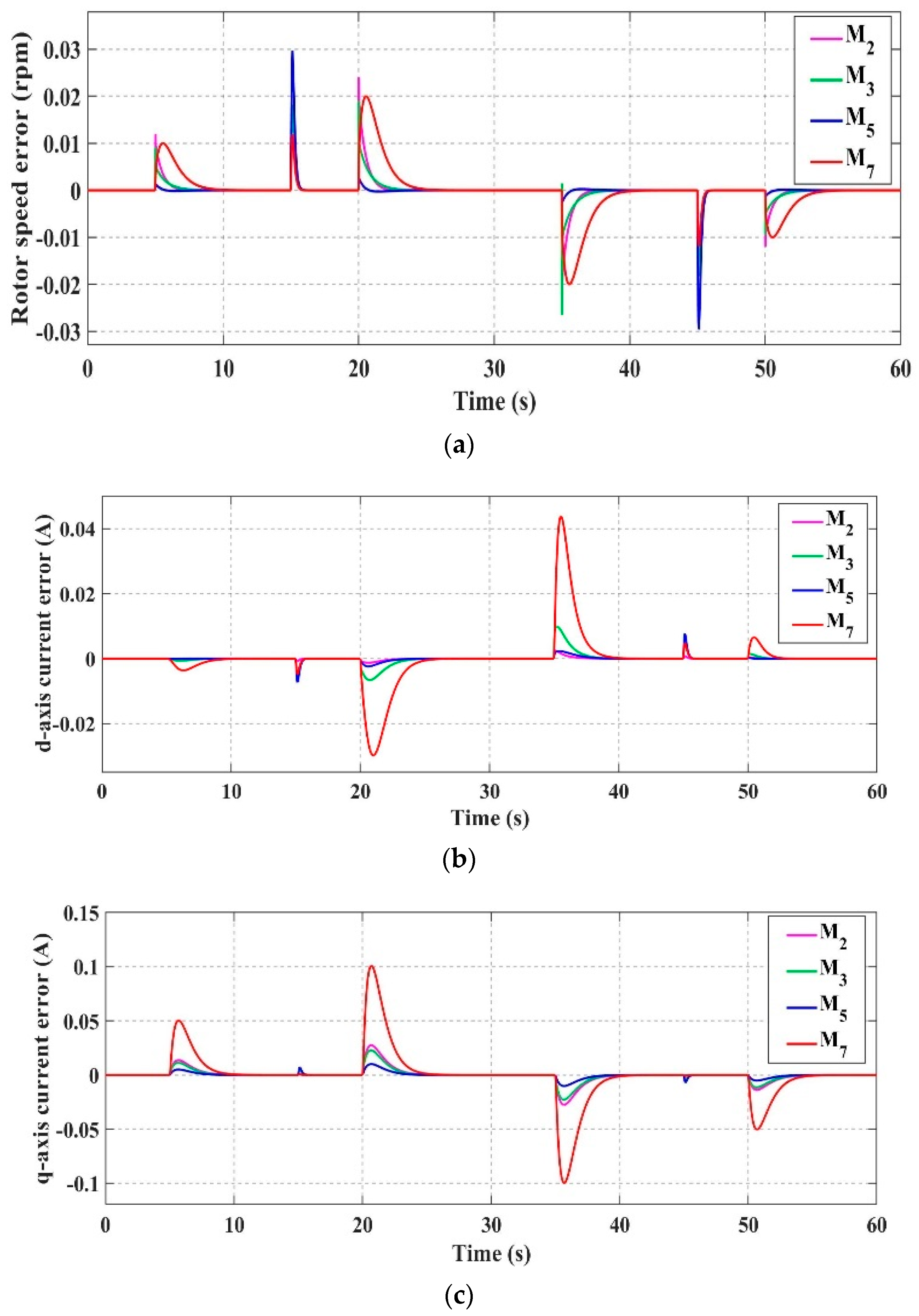
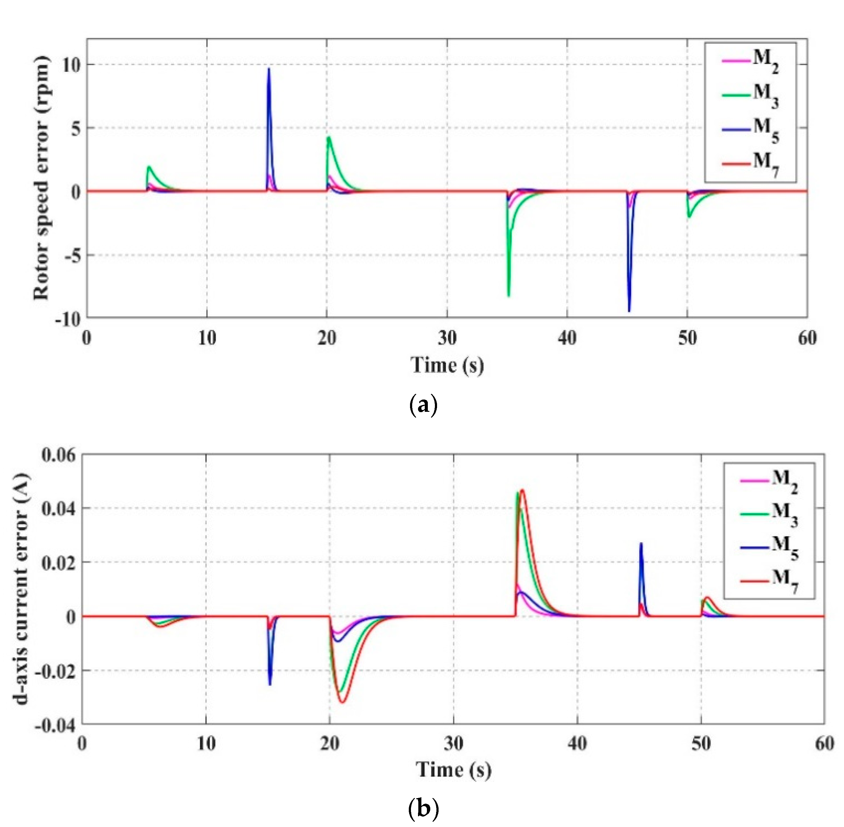
This section investigates the effectiveness of the two proposed gain tuning approaches using the vector and simplified control. The process of determining the gains is done offline and does not add any computational burden to the control system. Motors M2, M3, M5 and M7 are evaluated using the gains determined by both the proposed offline tuning methods consisting of some simple linear and non-linear mathematical equations. These four motors are examined under different load conditions, and the variations in the d-q axis currents and the rotor speed are monitored. The actual values of , and are compared with their reference values, and the respective errors are plotted to discuss the feasibility of the given control strategies. Figure 9 depicts the aforementioned errors for the vector control approach for all the four PMSMs considered for validation. For the simplified control approach, only the rotor speed error and the d-axis current error is mentioned in Figure 10 as the q-axis current is not taken into account.
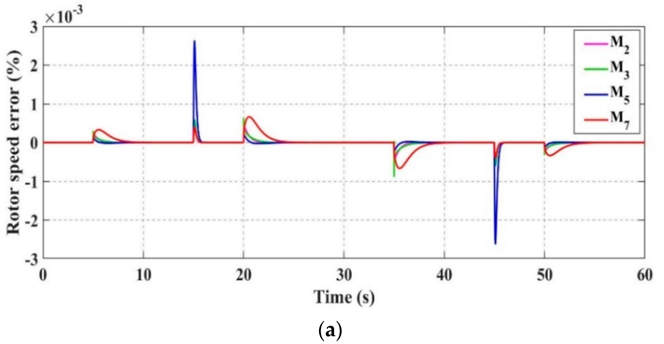
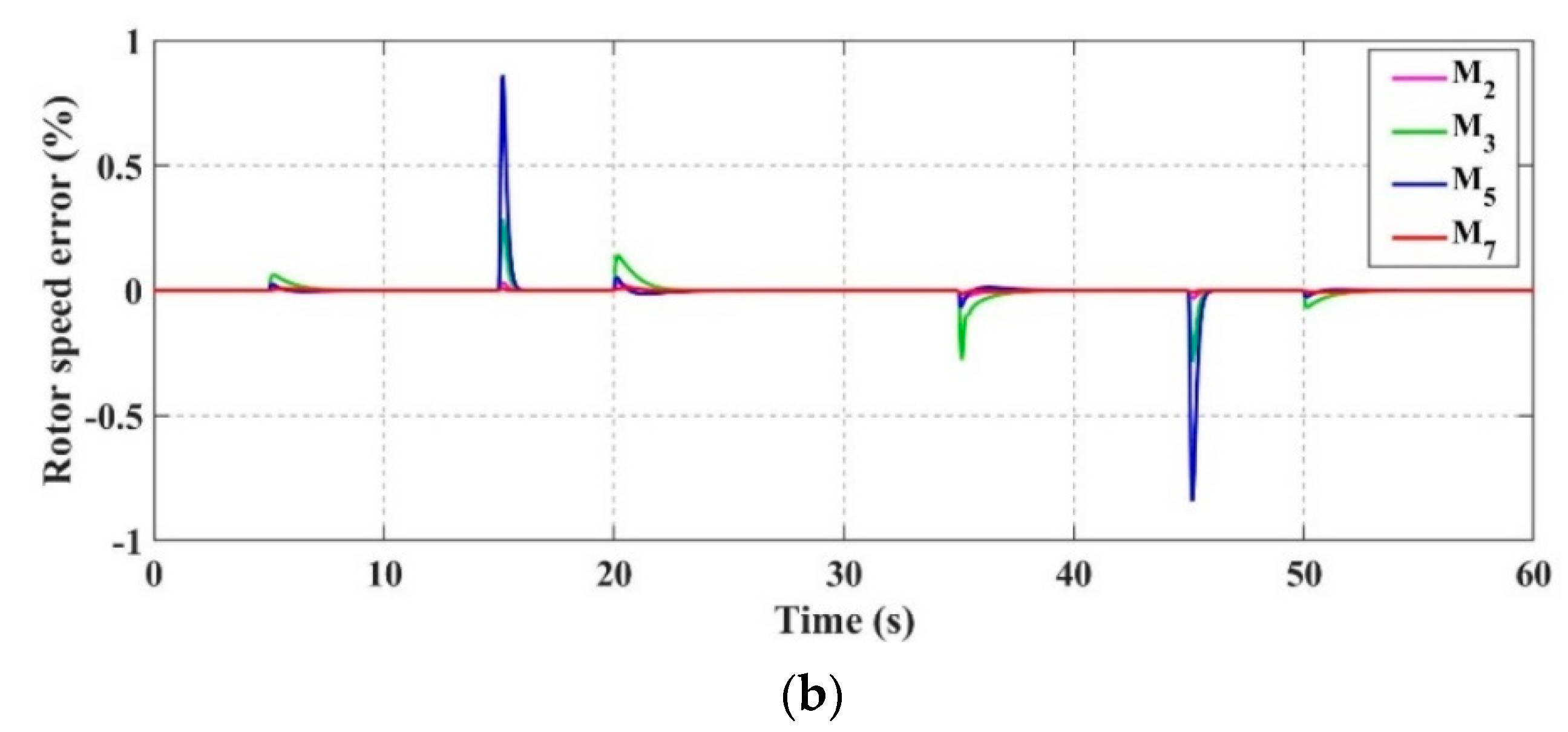
For the vector control approach, the maximum rotor speed error w.r.t the rated speed is noted as 0.0027% for motor M5. Also, the errors in d-q axis currents are very minimal, which proves the high accuracy of this tuning method. In simplified control strategy, it can be seen that the maximum percentage error in the rotor speed is 0.85%, which occurs for motor M5 and the d-axis current error is also not significant. To compare the accuracy of both the control techniques, the rotor speed errors in percentage (%) are represented in Figure 11. From Table 2, it can be seen that the vector control strategy has better overall performance and accuracy compared to the simplified control.
Although, both the proposed methods give good results with minimum errors, it is required to validate these techniques under the effect of motor parameter variations. When a motor is used in any application, its parameters’ values change due to the increment of temperature. This also affects the performance of the motor which needs to be taken into consideration during its operation. It is found that the stator resistance increases with the increase in temperature, which degrades the motor output [43], while the magnetic flux decreases with the increase in magnet temperature [44]. When the temperature increases up to °C, the stator resistance can vary by nearly 20% [43], while there is a decrement of magnetic flux by 10% under almost the same operating conditions [44]. These factors are considered and the integral absolute errors (IAE) for the speed tracking of all the validation motors are calculated in Table 3 under the influence of parameter variations. Integral absolute error can be defined as:
where represents the speed error.
To further analyze the precision and effectiveness of both the proposed methods, a sensitivity analysis is carried out to select the best control algorithm. The ratio of a relative change in a function f to a relative change in a system parameter p is known as the sensitivity function [45]. Thus, the sensitivity can be given as [45]:
It can be seen that the sensitivity approaches zero, when an error in parameter p has less influence on the function f [45]. Under the nominal speed condition, the effect of the change in parameters of and on the speed tracking is investigated and shown in Table 4.
All the results in Table 3 and Table 4 show that the vector control strategy has better precision and accuracy compared to the simplified control method, along with a little disadvantage of using some complex mathematical expressions for the determination of the control gains. Thus, vector control method is a better choice for applications requiring high accuracy in the speed and current tracking of PMSMs, while the simplified control technique can be used for applications with acceptable precision levels. Moreover, both these methods use simple PI control approaches making them affordable. The simplified control strategy uses only two PI controllers compared to three in vector control, making it cheaper in real-time implementation. The use of simple linear equations in simplified control seems to be a good option for applications such as vacuum cleaners, water pumps, printers, and photocopier machines which do not need very high accuracy. However, the advantage of better control precision of the vector control technique outweighs the benefit of using simple linear mathematical expressions of simplified control in most of the practical applications.
6. Conclusions
This paper proposed two gain tuning methods for the control of PMSMs with minimum information of prior system dynamics. Both these strategies make use of generalized mathematical expressions to determine the values of all the required control gains. First, the vector control approach is used to obtain some mathematical equations consisting of the respective control gain and the motor power rating as the two variables. The accuracy of this method is verified when some new PMSMs are simulated using the calculated control gains from these equations. In the second method, the simplified control strategy is used, based on the PMSM modeling equations. The generated mathematical expressions from this approach make use of the product of the number of pole pairs and flux linkage to find the required control gains. This method has the advantage of using only two PI controllers due to the elimination of the typical cascaded control structure. Furthermore, this method uses simple linear mathematical equations compared to the complex expressions derived from the vector control approach. This method is also verified by simulating the new PMSMs and calculating the rotor speed and d-axis current errors. It is found that the vector control technique has better accuracy compared to the simplified control method. Compared to the existing conventional control gain tuning methods, the proposed strategies are easier to implement and less time consuming in the real system. Validation carried out using numerous PMSMs with various power ratings of up to 7.5 kW is considered in this paper. Future work may envision the use of motors with higher power ratings.
Author Contributions
Conceptualization, R.K.L. and H.C.; methodology, R.K.L., H.C. and M.A.; software, R.K.L., H.C. and M.A.; validation, R.K.L. and H.C.; formal analysis, R.K.L. and H.C.; investigation, R.K.L., H.C. and M.A.; resources, H.C.; data curation, R.K.L., H.C. and M.A.; writing—original draft preparation, R.K.L., H.C. and M.A.; writing—review and editing, R.K.L., H.C., M.A. and S.L.; visualization, R.K.L., H.C. and M.A.; supervision, H.C. and S.L.; project administration, H.C.; funding acquisition, H.C. All authors have read and agreed to the published version of the manuscript.
Funding
This research was funded by Natural Sciences and Engineering Research Council of Canada, grant number 315082.
Institutional Review Board Statement
Not applicable.
Informed Consent Statement
Not applicable.
Data Availability Statement
No new data were created or analyzed in this study. Data sharing is not applicable to this article.
Conflicts of Interest
The authors declare no conflict of interest.
Abbreviations
| List of Symbols: | |
| Rotor position | |
| Rotor angular velocity | |
| , | d-q axis current components |
| , | d-q axis voltage components |
| , | d-q axis stator inductances |
| Stator resistance | |
| Rotor moment of inertia | |
| Viscous friction coefficient | |
| Load torque | |
| Number of pole pairs | |
| Magnetic flux linkage | |
| , | d-q axis reference currents |
| Speed controller PI gains | |
| current controller PI gains | |
| current controller PI gains | |
| Speed error | |
| current error | |
| current error | |
References
- Fartash Toloue, S.; Kamali, S.H.; Moallem, M. Multivariable sliding-mode extremum seeking PI tuning for current control of a PMSM. IET Electr. Power Appl. 2020, 14, 348–356. [Google Scholar] [CrossRef]
- Konghirun, M.; Xu, L. A Fast Transient-Current Control Strategy in Sensorless Vector-Controlled Permanent Magnet Synchronous Motor. IEEE Trans. Power Electron. 2006, 21, 1508–1512. [Google Scholar] [CrossRef]
- Li, S.; Won, H.; Fu, X.; Fairbank, M.; Wunsch, D.C.; Alonso, E. Neural-Network Vector Controller for Permanent-Magnet Synchronous Motor Drives: Simulated and Hardware-Validated Results. IEEE Trans. Cybern. 2020, 50, 3218–3230. [Google Scholar] [CrossRef] [PubMed]
- Martinez, D.I.; De Rubio, J.J.; Vargas, T.M.; Garcia, V.; Ochoa, G.; Balcazar, R.; Cruz, D.R.; Aguilar, A.; Novoa, J.F.; Aguilar-Ibañez, C. Stabilization of Robots with a Regular Containing the Sigmoid Mapping. IEEE Access 2020, 8, 89479–89488. [Google Scholar] [CrossRef]
- De Jesús Rubio, J.; Ochoa, G.; Mujica-Vargas, D.; Garcia, E.; Balcazar, R.; Elias, I.; Cruz, D.R.; Juarez, C.F.; Aguilar, A.; Novoa, J.F. Structure Regulator for the Perturbations Attenuation in a Quadrotor. IEEE Access 2019, 7, 138244–138252. [Google Scholar] [CrossRef]
- Escobedo-Alva, J.O.; García-Estrada, E.C.; Páramo-Carranza, L.A.; Meda-Campaña, J.A.; Tapia-Herrera, R. Theoretical Application of a Hybrid Observer on Altitude Tracking of Quadrotor Losing GPS Signal. IEEE Access 2018, 6, 76900–76908. [Google Scholar] [CrossRef]
- Rubio, J.D.J.; Martinez, D.I.; Garcia, V.; Gutierrez, G.J.; Vargas, T.M.; Ochoa, G.; Balcazar, R.; Pacheco, J.; Meda-Campana, J.A.; Mujica-Vargas, D. The Perturbations Estimation in Two Gas Plants. IEEE Access 2020, 8, 83081–83091. [Google Scholar] [CrossRef]
- Aguilar-Ibanez, C.; Suarez-Castanon, M.S. A Trajectory Planning Based Controller to Regulate an Uncertain 3D Overhead Crane System. Int. J. Appl. Math. Comput. Sci. 2019, 29, 693–702. [Google Scholar] [CrossRef] [Green Version]
- García-Sánchez, J.R.; Tavera-Mosqueda, S.; Silva-Ortigoza, R.; Hernández-Guzmán, V.M.; Sandoval-Gutiérrez, J.; Marcelino-Aranda, M.; Taud, H.; Marciano-Melchor, M. Robust Switched Tracking Control for Wheeled Mobile Robots Considering the Actuators and Drivers. Sensors 2018, 18, 4316. [Google Scholar] [CrossRef] [Green Version]
- Li, S.; Gu, H. Fuzzy Adaptive Internal Model Control Schemes for PMSM Speed-Regulation System. IEEE Trans. Ind. Inform. 2012, 8, 767–779. [Google Scholar] [CrossRef]
- Baik, I.C.; Kim, K.H.; Youn, M.J. Robust nonlinear speed control of PM synchronous motor using boundary layer integral sliding mode control technique. IEEE Trans. Control Syst. Technol. 2000, 8, 47–54. [Google Scholar] [CrossRef]
- Liang, D.; Li, J.; Qu, R.; Kong, W. Adaptive Second-Order Sliding-Mode Observer for PMSM Sensorless Control Considering VSI Nonlinearity. IEEE Trans. Power Electron. 2018, 33, 8994–9004. [Google Scholar] [CrossRef]
- Mohamed, Y.A.I. Design and Implementation of a Robust Current-Control Scheme for a PMSM Vector Drive with a Simple Adaptive Disturbance Observer. IEEE Trans. Ind. Electron. 2007, 54, 1981–1988. [Google Scholar] [CrossRef]
- Zhang, B.T.; Pi, Y. Robust fractional order proportion-plus-differential controller based on fuzzy inference for permanent magnet synchronous motor. IET Control Theory Appl. 2012, 6, 829–837. [Google Scholar] [CrossRef]
- Ping, Z.; Wang, T.; Huang, Y.; Wang, H.; Lu, J.; Li, Y. Internal Model Control of PMSM Position Servo System: Theory and Experimental Results. IEEE Trans. Ind. Inform. 2020, 16, 2202–2211. [Google Scholar] [CrossRef]
- Türker, T.; Buyukkeles, U.; Bakan, A.F. A Robust Predictive Current Controller for PMSM Drives. IEEE Trans. Ind. Electron. 2016, 63, 3906–3914. [Google Scholar] [CrossRef]
- Carpiuc, S.; Lazar, C. Fast Real-Time Constrained Predictive Current Control in Permanent Magnet Synchronous Machine-Based Automotive Traction Drives. IEEE Trans. Transp. Electrif. 2015, 1, 326–335. [Google Scholar] [CrossRef]
- Wang, W.; Fan, Y.; Chen, S.; Zhang, Q. Finite control set model predictive current control of a five-phase PMSM with virtual voltage vectors and adaptive control set. CES Trans. Electr. Mach. Syst. 2018, 2, 136–141. [Google Scholar] [CrossRef]
- Xie, G.; Lu, K.; Dwivedi, S.K.; Rosholm, J.R.; Blaabjerg, F. Minimum-Voltage Vector Injection Method for Sensorless Control of PMSM for Low-Speed Operations. IEEE Trans. Power Electron. 2016, 31, 1785–1794. [Google Scholar] [CrossRef]
- Prior, G.; Krstic, M. Quantized-Input Control Lyapunov Approach for Permanent Magnet Synchronous Motor Drives. IEEE Trans. Control Syst. Technol. 2013, 21, 1784–1794. [Google Scholar] [CrossRef]
- Liu, H.; Li, S. Speed Control for PMSM Servo System Using Predictive Functional Control and Extended State Observer. IEEE Trans. Ind. Electron. 2012, 59, 1171–1183. [Google Scholar] [CrossRef]
- Formentini, A.; Trentin, A.; Marchesoni, M.; Zanchetta, P.; Wheeler, P. Speed Finite Control Set Model Predictive Control of a PMSM Fed by Matrix Converter. IEEE Trans. Ind. Electron. 2015, 62, 6786–6796. [Google Scholar] [CrossRef]
- Jung, J.; Choi, Y.; Leu, V.Q.; Choi, H.H. Fuzzy PI-type current controllers for permanent magnet synchronous motors. IET Electr. Power Appl. 2011, 5, 143–152. [Google Scholar] [CrossRef]
- Kung, Y.; Tsai, M. FPGA-Based Speed Control IC for PMSM Drive with Adaptive Fuzzy Control. IEEE Trans. Power Electron. 2007, 22, 2476–2486. [Google Scholar] [CrossRef]
- Barkat, S.; Tlemçani, A.; Nouri, H. Noninteracting Adaptive Control of PMSM Using Interval Type-2 Fuzzy Logic Systems. IEEE Trans. Fuzzy Syst. 2011, 19, 925–936. [Google Scholar] [CrossRef]
- Yang, Y.; Vilathgamuwa, D.M.; Rahman, M.A. Implementation of an artificial-neural-network-based real-time adaptive controller for an interior permanent-magnet motor drive. IEEE Trans. Ind. Appl. 2003, 39, 96–104. [Google Scholar] [CrossRef]
- Yu, J.; Shi, P.; Dong, W.; Chen, B.; Lin, C. Neural Network-Based Adaptive Dynamic Surface Control for Permanent Magnet Synchronous Motors. IEEE Trans. Neural Netw. Learn. Syst. 2015, 26, 640–645. [Google Scholar] [CrossRef] [PubMed]
- Sheng, L.; Xiaojie, G.; Lanyong, Z. Robust Adaptive Backstepping Sliding Mode Control for Six-Phase Permanent Magnet Synchronous Motor Using Recurrent Wavelet Fuzzy Neural Network. IEEE Access 2017, 5, 14502–14515. [Google Scholar] [CrossRef]
- Lin, F.; Yang, K.; Sun, I.; Chang, J. Intelligent position control of permanent magnet synchronous motor using recurrent fuzzy neural cerebellar model articulation network. IET Electr. Power Appl. 2015, 9, 248–264. [Google Scholar] [CrossRef]
- Lin, F.; Sun, I.; Yang, K.; Chang, J. Recurrent Fuzzy Neural Cerebellar Model Articulation Network Fault-Tolerant Control of Six-Phase Permanent Magnet Synchronous Motor Position Servo Drive. IEEE Trans. Fuzzy Syst. 2016, 24, 153–167. [Google Scholar] [CrossRef]
- Niu, F.; Li, K.; Wang, Y. Direct Torque Control for Permanent-Magnet Synchronous Machines Based on Duty Ratio Modulation. IEEE Trans. Ind. Electron. 2015, 62, 6160–6170. [Google Scholar] [CrossRef]
- Vafaie, M.H.; Mirzaeian Dehkordi, B.; Moallem, P.; Kiyoumarsi, A. A New Predictive Direct Torque Control Method for Improving Both Steady-State and Transient-State Operations of the PMSM. IEEE Trans. Power Electron. 2016, 31, 3738–3753. [Google Scholar] [CrossRef]
- Mohamed, Y.A.I. Direct Instantaneous Torque Control in Direct Drive Permanent Magnet Synchronous Motors—A New Approach. IEEE Trans. Energy Convers. 2007, 22, 829–838. [Google Scholar] [CrossRef]
- Xuan-Mung, N.; Hong, S.K. Improved Altitude Control Algorithm for Quadcopter Unmanned Aerial Vehicles. Appl. Sci. 2019, 9, 2122. [Google Scholar] [CrossRef] [Green Version]
- Salih, A.L.; Moghavemmi, M.; Mohamed, H.A.F.; Gaeid, K.S. Modelling and PID Controller Design for a Quadrotor Unmanned Air Vehicle. In Proceedings of the IEEE International Conference on Automation, Quality and Testing, Robotics (AQTR), Cluj-Napoca, Romania, 28–30 May 2010; pp. 1–5. [Google Scholar]
- Xuan-Mung, N.; Hong, S.K.; Nguyen, N.P.; Le, T.L. Autonomous Quadcopter Precision Landing onto a Heaving Platform: New Method and Experiment. IEEE Access 2020, 8, 167192–167202. [Google Scholar] [CrossRef]
- Grassi, E.; Tsakalis, K. PID controller tuning by frequency loop-shaping: Application to diffusion furnace temperature control. IEEE Trans. Control Syst. Technol. 2000, 8, 842–847. [Google Scholar] [CrossRef]
- Kim, K.; Schaefer, R.C. Tuning a PID controller for a digital excitation control system. IEEE Trans. Ind. Appl. 2005, 41, 485–492. [Google Scholar] [CrossRef]
- Park, D.; Yu, H.; Xuan-Mung, N.; Lee, J.; Hong, S.K. Multicopter PID Attitude Controller Gain Auto-tuning through Reinforcement Learning Neural Networks. In Proceedings of the 2019 2nd International Conference on Control and Robot Technology, Jeju Island, Korea, 12–14 December 2019; pp. 80–84. [Google Scholar]
- Hang, C.C.; Sin, K.K. On-line auto tuning of PID controllers based on the cross-correlation technique. IEEE Trans. Ind. Electron. 1991, 38, 428–437. [Google Scholar] [CrossRef]
- Habibi, H.; Rahimi Nohooji, H.; Howard, I. Adaptive PID Control of Wind Turbines for Power Regulation with Unknown Control Direction and Actuator Faults. IEEE Access 2018, 6, 37464–37479. [Google Scholar] [CrossRef]
- Na, M.G. Auto-tuned PID controller using a model predictive control method for the steam generator water level. IEEE Trans. Nucl. Sci. 2001, 48, 1664–1671. [Google Scholar]
- Jun, B.-S.; Park, J.S.; Choi, J.-H.; Lee, K.-D.; Won, C.-Y. Temperature Estimation of Stator Winding in Permanent Magnet Synchronous Motors Using d-Axis Current Injection. Energies 2018, 11, 2033. [Google Scholar] [CrossRef] [Green Version]
- Lai, C.; Feng, G.; Mukherjee, K.; Kar, N.C. Investigations of the Influence of PMSM Parameter Variations in Optimal Stator Current Design for Torque Ripple Minimization. IEEE Trans. Energy Convers. 2017, 32, 1052–1062. [Google Scholar] [CrossRef]
- Bolognani, S.; Peretti, L.; Zigliotto, M. Parameter Sensitivity Analysis of an Improved Open-Loop Speed Estimate for Induction Motor Drives. IEEE Trans. Power Electron. 2008, 23, 2127–2135. [Google Scholar] [CrossRef]
Figure 1.
Vector Control Scheme.

Figure 2.
Simplified control scheme.

Figure 3.
Relative rotor speed percentage errors (%).

Figure 4.
Motor M8 tracking performance. (a) Speed; (b) d-q axis currents.

Figure 5.
PI control gains versus motor power ratings. (a) ; (b) ; (c) (d) ; (e) ; (f)

Figure 6.
Relative rotor speed percentage errors (%).

Figure 7.
Motor M8 tracking performance. (a) Speed; (b) d-q axis currents.

Figure 8.
Plots of PI control gains versus product values. (a) ; (b) ; (c) (d)

Figure 9.
Errors measured in the vector control method. (a) Rotor speed error; (b) d-axis current error; (c) q-axis current error.
Figure 9.
Errors measured in the vector control method. (a) Rotor speed error; (b) d-axis current error; (c) q-axis current error.

Figure 10.
Errors measured in simplified control method. (a) Rotor speed error; (b) d-axis current error.
Figure 10.
Errors measured in simplified control method. (a) Rotor speed error; (b) d-axis current error.

Figure 11.
Rotor speed errors in percentage (%). (a) Vector control; (b) simplified control.


Table 1.
Parameters of all permanent magnet synchronous motors (PMSMs).
| Parameters. | Symbol | M1 | M2 | M3 | M4 | M5 | M6 | M7 | M8 |
|---|---|---|---|---|---|---|---|---|---|
| Rated power/(kW) | p | 0.15 | 0.25 | 0.4 | 0.5 | 1.49 | 2 | 3.8 | 7.5 |
| Rated speed/(rpm) | 2400 | 4000 | 3000 | 3000 | 1125 | 1000 | 3000 | 1500 | |
| Number of pole pairs | 2 | 5 | 4 | 4 | 6 | 4 | 6 | 4 | |
| Stator resistance/(Ω) | 2.62 × 10⁻³ | 0.18 | 1.73 | 1.38 | 2.9 | 2.73 | 0.94 | 0.44 | |
| d-axis stator inductance/(mH) | 0.23 | 0.25 | 3.46 | 3.7 | 5.43 | 14.5 | 7 | 8.39 | |
| q-axis stator inductance/(mH) | 0.23 | 0.25 | 3.46 | 3.7 | 8.58 | 31.18 | 8.3 | 8.39 | |
| Permanent magnet flux/(Wb) | 12.45 × 10⁻³ | 15.92 × 10⁻³ | 0.03 | 0.045 | 0.043 | 0.55 | 0.25 | 0.168 | |
| Moment of inertia/(kg.m2) | 9 × 10⁻⁵ | 2.91 × 10⁻⁴ | 3 × 10⁻⁴ | 5.5 × 10⁻⁴ | 4.5 × 10⁻⁴ | 0.011 | 2 × 10⁻³ | 1.5 × 10⁻³ | |
| Viscous friction coefficient/(N.m.s/rad) | 1.32 × 10⁻⁵ | 3.63 × 10⁻⁴ | 5.8 × 10⁻⁴ | 7.2 × 10⁻⁴ | 1.2 × 10⁻⁴ | 0.02 | 0.038 | 4 × 10⁻⁵ |
Table 2.
Comparison of average rotor speed error (%).
| Validation Motors | Vector Control | Simplified Control |
|---|---|---|
| M2 | 1.65 × 10⁻⁵ | 1.5 × 10⁻³ |
| M3 | 1.86 × 10⁻⁵ | 9.4 × 10⁻³ |
| M5 | 2.91 × 10⁻⁵ | 0.01 |
| M7 | 6.3 × 10⁻⁵ | 8 × 10⁻⁴ |
Table 3.
Integral absolute error (IAE) comparison under varying motor parameters.
| Validation Motors | IAE (Nominal) | |||||
|---|---|---|---|---|---|---|
| Vector Control | Simplified Control | Vector Control | Simplified Control | Vector Control | Simplified Control | |
| M2 | 198.38 | 17,908.32 | 198.38 | 21,455.19 | 220.59 | 19,910.53 |
| M3 | 167.11 | 84,645.15 | 167.1 | 101,574.14 | 185.72 | 94,050.17 |
| M5 | 98.28 | 35,542.29 | 98.28 | 42,573.7 | 108.42 | 39,429.06 |
| M7 | 566.69 | 7625.47 | 566.69 | 9565.21 | 629.52 | 8318.39 |
Table 4.
Sensitivity analysis.
| Validation Motors | ||||
|---|---|---|---|---|
| Vector Control | Simplified Control | Vector Control | Simplified Control | |
| M2 | 1.62 × 10⁻⁴ | 0.005 | 0.015 | 0.009 |
| M3 | 8.34 × 10⁻⁴ | 0.028 | 0.008 | 0.068 |
| M5 | 7.11 × 10⁻⁴ | 0.037 | 0.005 | 0.059 |
| M7 | 2.67 × 10⁻⁴ | 0.008 | 0.013 | 0.042 |
Publisher’s Note: MDPI stays neutral with regard to jurisdictional claims in published maps and institutional affiliations. |
© 2021 by the authors. Licensee MDPI, Basel, Switzerland. This article is an open access article distributed under the terms and conditions of the Creative Commons Attribution (CC BY) license (http://creativecommons.org/licenses/by/4.0/).
Share and Cite
MDPI and ACS Style
Lakhe, R.K.; Chaoui, H.; Alzayed, M.; Liu, S. Universal Control of Permanent Magnet Synchronous Motors with Uncertain Dynamics. Actuators 2021, 10, 49. https://0-doi-org.brum.beds.ac.uk/10.3390/act10030049
AMA Style
Lakhe RK, Chaoui H, Alzayed M, Liu S. Universal Control of Permanent Magnet Synchronous Motors with Uncertain Dynamics. Actuators. 2021; 10(3):49. https://0-doi-org.brum.beds.ac.uk/10.3390/act10030049
Chicago/Turabian StyleLakhe, Rishil Kirankumar, Hicham Chaoui, Mohamad Alzayed, and Shichao Liu. 2021. "Universal Control of Permanent Magnet Synchronous Motors with Uncertain Dynamics" Actuators 10, no. 3: 49. https://0-doi-org.brum.beds.ac.uk/10.3390/act10030049
Note that from the first issue of 2016, this journal uses article numbers instead of page numbers. See further details here.