
Soft Hybrid Suction Cup Capable of Sticking to Various Objects and Environments


Department of Systems and Control Engineering, Tokyo Institute of Technology, 2-12-1-S5-19 Ohokayama, Meguro-ku, Tokyo 152-8552, Japan
*
Author to whom correspondence should be addressed.
Actuators 2021, 10(3), 50; https://0-doi-org.brum.beds.ac.uk/10.3390/act10030050
Submission received: 4 December 2020
/
Revised: 2 March 2021
/
Accepted: 3 March 2021
/
Published: 5 March 2021
(This article belongs to the Special Issue Fluid Power Actuation Systems)
Abstract
:A universal suction cup that can stick to various objects expands the areas in which robots can work. However, the size, shape, and surface roughness of objects to which conventional suction cups can stick are limited. To overcome this challenge, we propose a new hybrid suction cup structure that uses the adhesive force of sticky gel and the suction force of negative pressure. In addition, a flexible and thin pneumatic balloon actuator with a check valve function is installed in the interior, enabling the controllable detachment from objects. The prototype has an outer diameter of 55 mm, a weight of 18.8 g, and generates an adsorption force of 80 N in the vertical direction and 60 N in the shear direction on porous walls where conventional suction cups struggle to adsorb. We confirmed that parts smaller than the suction cup and fragile potato chips are adsorbed by the prototype. Finally, the effectiveness of the proposed method is verified through experiments in which a drone with the prototypes can be attached to and detached from concrete walls and ceilings while flying; the possibility of adsorption to dusty and wet plates is discussed.
1. Introduction
The leech uses two suction cups on the front and back of the trunk and can move while repeatedly adsorbing and leaving the body surface of animals and various natural environments. If it is possible to artificially create a lightweight, high-power, and universal suction cup that can adsorb and detach from various objects in this way, the activity area of robots could be expanded. For example, an unmanned aerial vehicle (UAV) equipped with a perching mechanism can perform tapping sound inspections on bridges and tunnels. Thus far, UAVs with various types of perching functions have been developed [1,2,3,4,5,6,7]. A suction cup using negative pressure is considered an effective method, since its adsorption force is adjustable, and a relatively high adsorption force can be generated without fear of damaging the environment. After being attracted to a door, a drone can open it with wind pressure [8]. To further advance drone functionality, suction cups that provide sufficient supporting force in both the vertical and shear directions are required for various materials such as doors and walls. These suction cups are helpful to let the drone to approach the wall while generating negative pressure from them. In addition, if the end effector can easily adsorb, the areas that the manipulator can handle will be expanded [9,10,11,12,13,14,15,16]. In particular, the use of vacuum suction cups has been widely used in the industrial world because they can lift flat plates and large objects by simply pressing them.
However, the vacuum suction cup using negative pressure can only handle limited objects. That is, to maintain airtightness, the objects that can be handled by the suction cup are limited to those with a surface with few irregularities and a shape that can cover the entire suction cup. As the number of manufacturing lines handling custom-made products increases, one manipulator will be required to have the function of gripping objects with different shapes, sizes, surface roughness, and fragility. Considering the application to production lines that handle different types of products, the following conditions are imposed: (1) adsorption/detachment to various objects with (2) no pressing force required during adsorption and (3) an adsorption method that allows the manipulator to approach from a wide range of angles regardless of the shape of the object.
In this research, we constructed a hybrid suction cup that combines the adhesive force of adhesive gel and the suction force of negative pressure. The adhesive gel provided on the outer circumference of the bottom surface of the suction cup helps to maintain airtightness and to fix objects that are difficult to be adsorbed by negative pressure. In addition, the negative pressure adjusts the suction force and brings the object closer to the suction force. With the release balloon with a check valve sheet provided inside, the removal of the suction cup can be controlled. With this configuration, all of the above-mentioned problems (1–3) are solved.
In this paper, the configuration and operating principle of the hybrid suction cup are first described. Next, the mathematical model of the adsorption force and the manufacturing method are described. Then, the validity of the presented mathematical model is demonstrated through a basic experiment using a prototype suction cup. The results of its application to the handling operation of various objects are provided along with the evaluation of the adsorption performance on a surface covered with water or dust. Finally, we report the results of trying to stop the drone on the wall/ceiling using a drone equipped with the prototype suction cup, verifying the effectiveness of the proposed method.
2. Materials and Methods
2.1. Design Policy
In this research, we aim to realize a device that enables UAVs such as drones in flight to stop and detach on the ceiling or wall surface without special flight control, as well as that enables a manipulator to pick up and release various objects. Therefore, we will consider the device that meets the following conditions.
(1) Shape and structure: When adsorbed to the ceiling or wall, the shape is a disk so that the symmetry of the adsorption direction can be achieved. It has a compact (60 mm or less in diameter) and lightweight (50 g or less including the drive source) structure that can be mounted on a UAV with strict payload restrictions.
(2) Function: At the time of adsorption, we aim to easily stop the UAV by approaching it from a direction that is almost perpendicular to the wall surface or ceiling. In addition, at the time of departure, it is easy to operate the flight by releasing while exerting a thrust to balance with gravity without applying a special force depending on the direction. To achieve these operations, two states are supposed to be considered: a temporary adsorptive state that is positioned to prevent from slipping against the wall surface by light touching, and a stable adsorptive state (adhesive force over 50 N) that supports the weight of UAV by further applying energy. Two states are switched under control.
(3) Fixing target: We consider a method that can stably fix the material and unevenness that are often used for walls and ceilings. Specifically, mortar wall, tile surface, breathable plasterboard, etc. are targeted.
2.2. Problems in Previous Methods
Various adsorptive methods have been proposed as solutions in environments where the conventional vacuum suction cup cannot be applied. Devices using van der Waals forces are lightweight and easy to configure and have the potential to adsorb to various materials [17,18,19,20,21,22,23,24,25]. The direction in which it is easily peeled off is limited to a specific diagonal direction with respect to the contact surface. Therefore, these devices are difficult to apply to the operation of peeling off perpendicular to the contact surface. Electrostatic force can generate a relatively strong adsorption force on the wall surface of various materials [26,27]. However, it only works on smooth planes. It is hard to work on rough surface like the tile surface. The magnetic adsorption force [28] can generate an extremely high adsorption force, but the adsorption target is limited to ferromagnetic material. Regarding the adsorption principle of octopus suction cups, a method of indirectly generating negative pressure by enlarging the porous membrane was proposed [29]. Since multiple dispersed holes can independently generate negative pressure, this method facilitates the maintenance of airtightness even on uneven surfaces, but the suction force is weaker than the direct suction of negative pressure. Micro rubber suction cups adhering to rough surfaces to lift lightweight objects were also reported [30]. Adhesive strength is a method that makes it easy to fix to a relatively wide variety of materials regardless of the surface roughness [31]. However, relying solely on this method requires excessive force at the time of detachment.
2.3. Proposed Configuration and Operating Principle
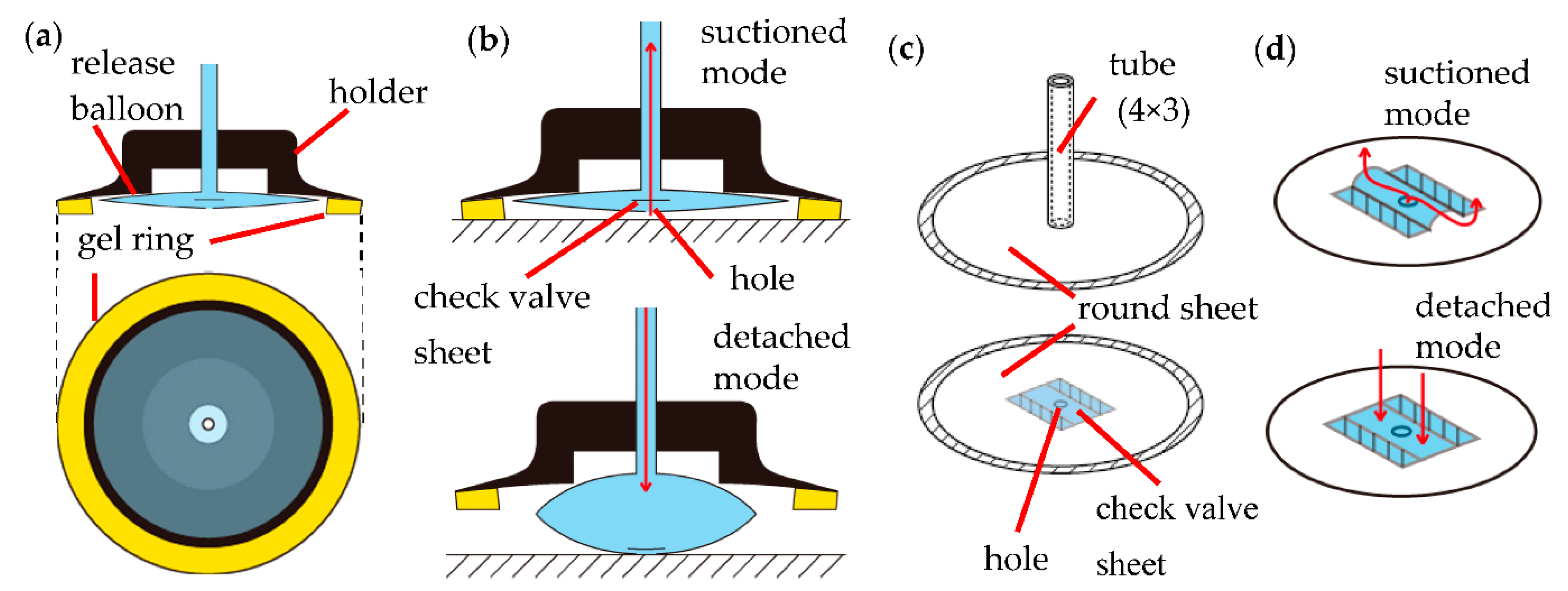
To overcome each of the above problems and to meet the conditions in Section 2.1, we propose a hybrid suction cup (HS cup) consisting of the following three parts: a hollow truncated cone holder, a ring-shaped sticky gel that covers the outer circumference of the bottom surface of the holder, and a release balloon stored inside the holder, as illustrated in Figure 1. The release balloon consists of two thin round sheets and a tube. The top sheet is connected to the tube. In addition, a hole is provided in the bottom sheet, and one check valve sheet is attached to cover the hole. The check valve sheet is rectangular, and one set of two opposite sides is welded to the round sheet on the bottom, but the other pair of sides is not welded.
At the time of suction, the inside of the release balloon is suctioned with a negative pressure while the gel ring is brought close to the object. The gel ring can adhere while passively adapting to the surface shape of the object, filling the gap between the object and the suction cup and improving the airtightness. When the inside of the release balloon is suctioned, a gap is created between the check valve sheet and the round sheet on the bottom, and the entire air inside the holder can be suctioned. Therefore, when the balloon is sealed, the suction force further increases as the absolute value of the negative pressure of the squirrel balloon increases. If airtightness cannot be ensured, it will be adsorbed to the object only by the adhesion of the gel ring.
At the time of detachment, the inside of the release balloon is pressurized with positive pressure. The check valve sheet is pressed against the round sheet on the bottom, the hole is closed, and the release balloon is inflated. As a result, the force that pulls the suction cup from the object acts.
2.4. Theoretical Modeling
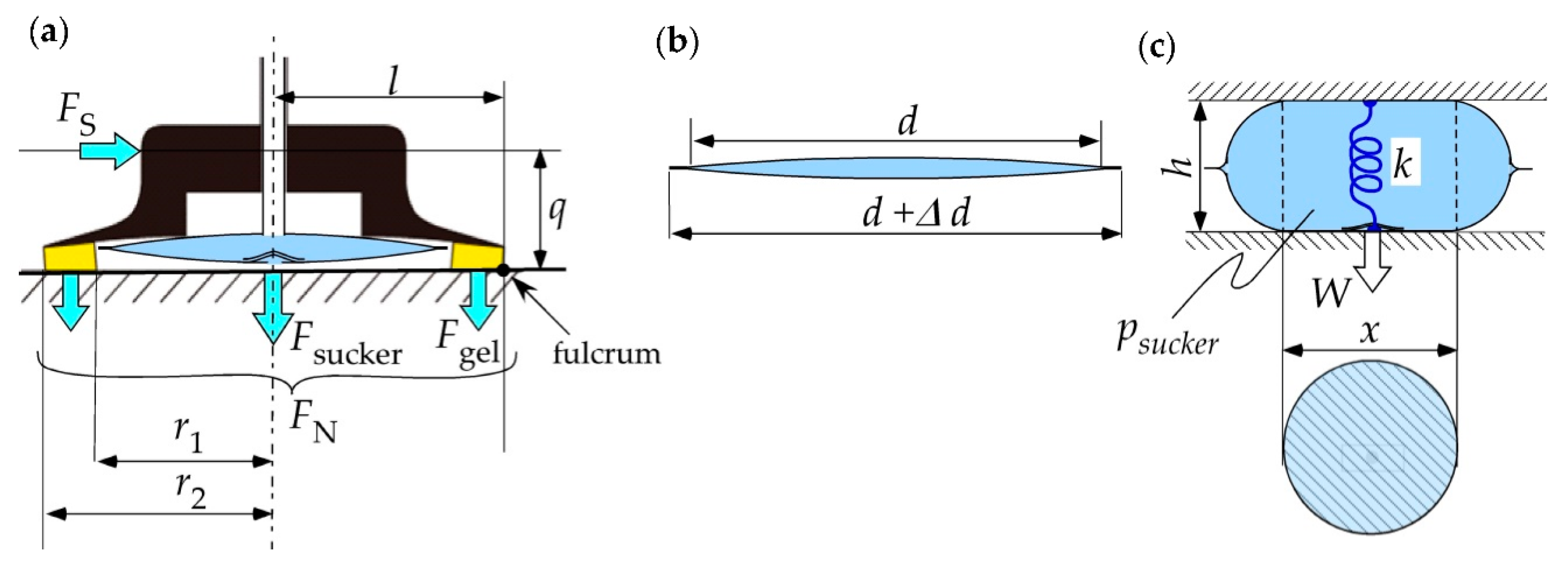
The adsorption force of HS cup is examined. To distinguish between the force by suction and the one by adhesion, the force due to negative pressure is the suction force , the force due to adhesive gel is the adhesive force and their resultant force is the adsorption force . Let be half the inner diameter of the gel and be half the outer diameter, as shown in Figure 2a. Let be the adhesive force per unit area of the gel to the adsorption surface, which varies with the material of the object; and be the pressure inside HS cup in the gauge pressure display.
Adhesive force is proportional to the contact area between the gel ring and the object.
The suction force can be expressed as the product of the area on which the negative pressure acts and the pressure inside the suction cup.
The adsorption force, that is, the supporting force perpendicular to HS cup, can be expressed as these resultant forces.
Next, the supporting force of the HS cup in the shear direction is examined. There are two situations in which the HS cup cannot be supported in the shearing direction: sliding down and pealing. Sliding occurs when the load in the shear direction exceeds the maximum static friction force , where is the maximum coefficient of static friction between the gel ring and the object. Pealing occurs when the moment due to the load in the shear direction exceeds the moment by the force in the vertical direction. Here, represents the distance between the action line of the load in the shear direction and the fulcrum, and represents the distance between the center line of HS cup and the fulcrum. Therefore, the load that can support the shear direction is determined as these minimum values.
The detaching force of the release balloon is considered as follows: Consider a cross-section that passes through the center of the release balloon, as shown in Figure 2b. Here, we make three assumptions. First, the cross-sectional circumference of the release balloon is constant during pressurization. Second, the side surface that does not contact the object has the maximum volume, so it is deformed into a semicircular shape. Third, the restoring force of the release balloon can be approximated as an ideal linear spring with a natural length of 0.
Assuming that the diameter of the inside of the release balloon in initial condition is d, the diameter x of the circle in contact with the object when inflated by the height h is expressed by the following equation, where indicates the width of welding:
At this time, the release force W of the release balloon can be expressed by the following equation, where the spring constant of its restoring force is expressed as k:
The outer diameter d of the release balloon needs to be designed to satisfy the following two equations from the point of geometrical condition and the force balance:
2.5. Fabrication
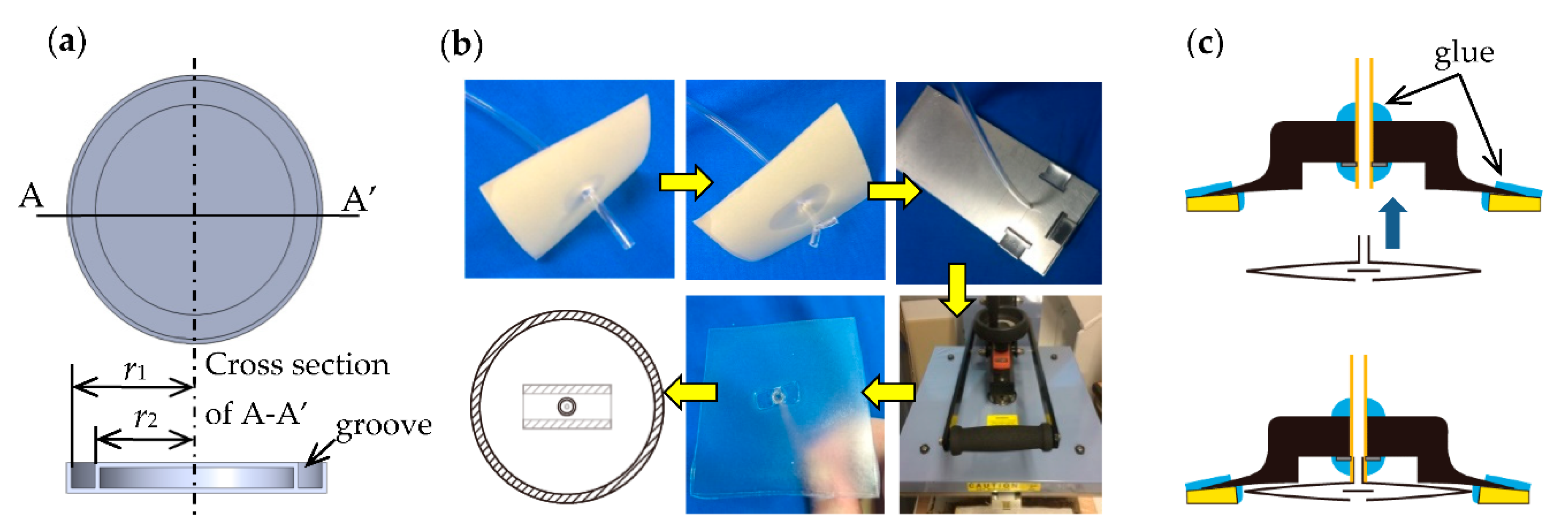
The HS cup can be fabricated by making a gel ring and a release balloon separately and attaching them to a holder.
For the gel ring, urethane gel was used, which was manufactured by the following procedure: A mold with a ring-shaped groove was fabricated with a 3D printer (UP Box+, Japan 3D Printer, Koto-ku, Japan) with a resolution of 0.1 mm, as shown in Figure 3a. The thickness of the outer circumference of the mold should be about 1 mm. The gel stock solution was a polyol blend as the main ingredient, with isocyanate and additives as curing agents; they were mixed in a weight ratio of 3:1. In this study, Asuka-C, a human skin gel stock solution manufactured by EXSEAL, Japan, was selected as the gel stock solution. Next, a mold release material (barrier coat) was applied to the surface of the mold. The above-prepared mixed solution was poured into the mold, placed in a defoamer, the pressure was reduced, and the solution was cured for about 5. We cut the outer circumference of the mold and removed the gel ring.
The release balloon can be fabricated as follows, as shown in Figure 3b: First, fabricated the upper sheet. A hole is made in the urethane sheet with a thickness of 0.2 mm, and a urethane tube with an outer diameter of 4 mm and an inner diameter of 3 mm is passed through the hole. Break the tip of the tube by about 5 mm and press it against the tip while applying heat to keep it open. Sandwich the above sheet between two metal plates. Heat the sheet and tube with a heat vise. Next, fabricate the lower sheet. Cut a 0.2 mm thick urethane sheet into a circle with an outer diameter of 44 mm. Create a hole with a diameter of about 1 mm in the center. A rectangular check valve sheet with a length of 10 mm and a width of 20 mm is placed over this hole, and the two sides in the longitudinal direction are welded to the lower sheet. Overlay the upper sheet and the lower sheet and weld a width of about 2 mm.
As a holder, use a vacuum pad with a diameter of 50 mm. Attach the gel ring and release balloon to the holder, and fill the gap with glue (KONISHI’s versatile SU Premium Hard, Osaka, Japan) to improve airtightness, as shown in Figure 3c.
3. Results
3.1. Prototype
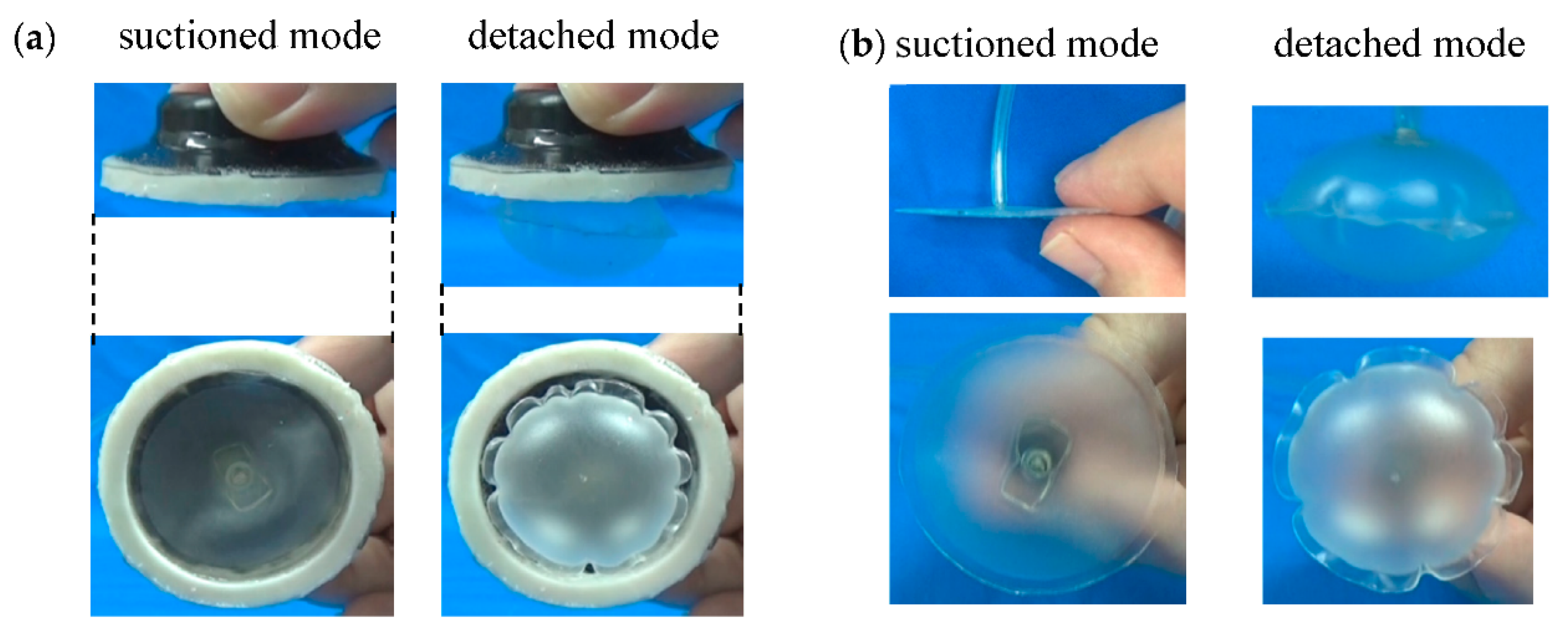
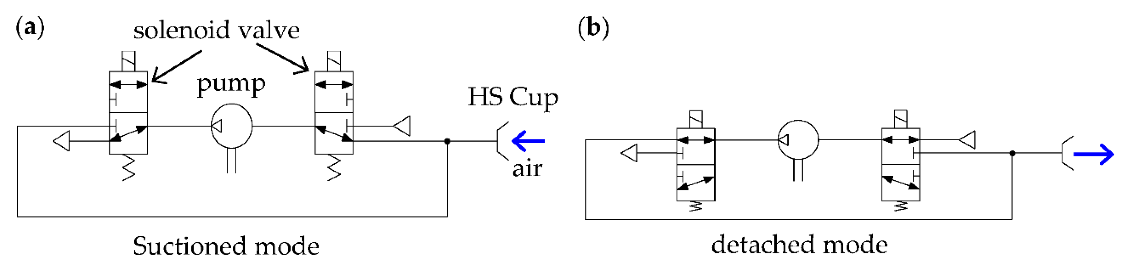
Figure 4 shows the prototype of developed HS cup according to the fabricating procedure described in the previous section. The specifications of this suction cup are as listed in Table 1. As a power source, only a handy sized pneumatic pump (1010VD DC, 15 g in weight, Thomas Pump Co., Aurora, IL, USA) capable of supplying a positive pressure of around 60 kPa is sufficient. As shown in the pneumatic circuit diagram in Figure 5, it is possible to realize both suction and detachment without a vacuum pump by operating with two solenoid switching valves (LHDA1233115H, Lee Co., Westbrook, CT, USA).
3.2. Adsorption on Various Objects
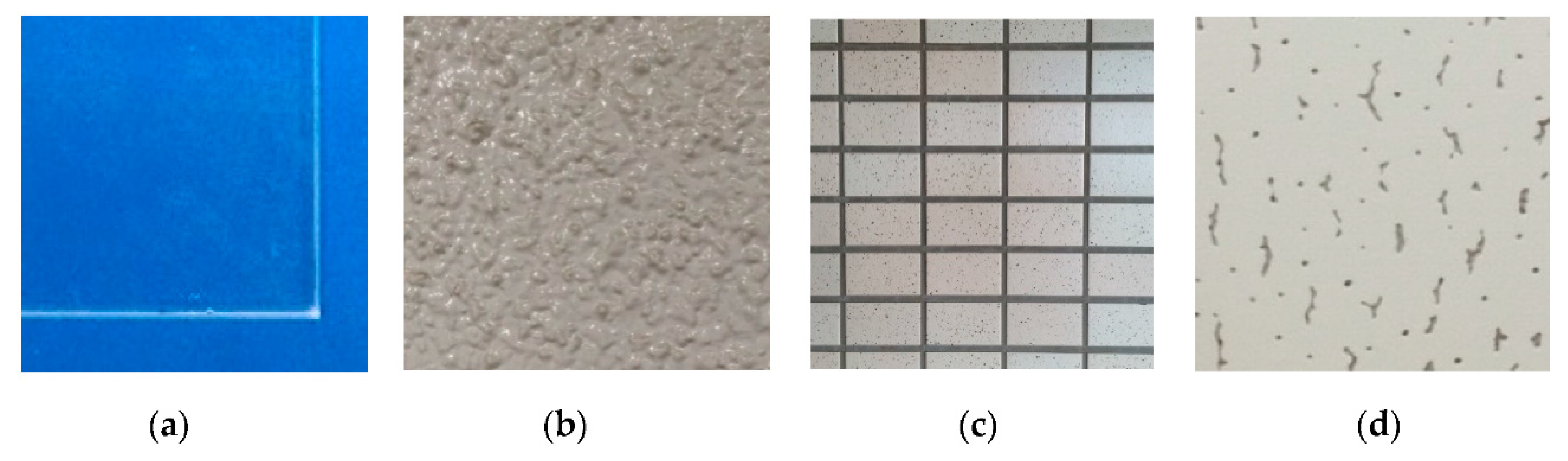
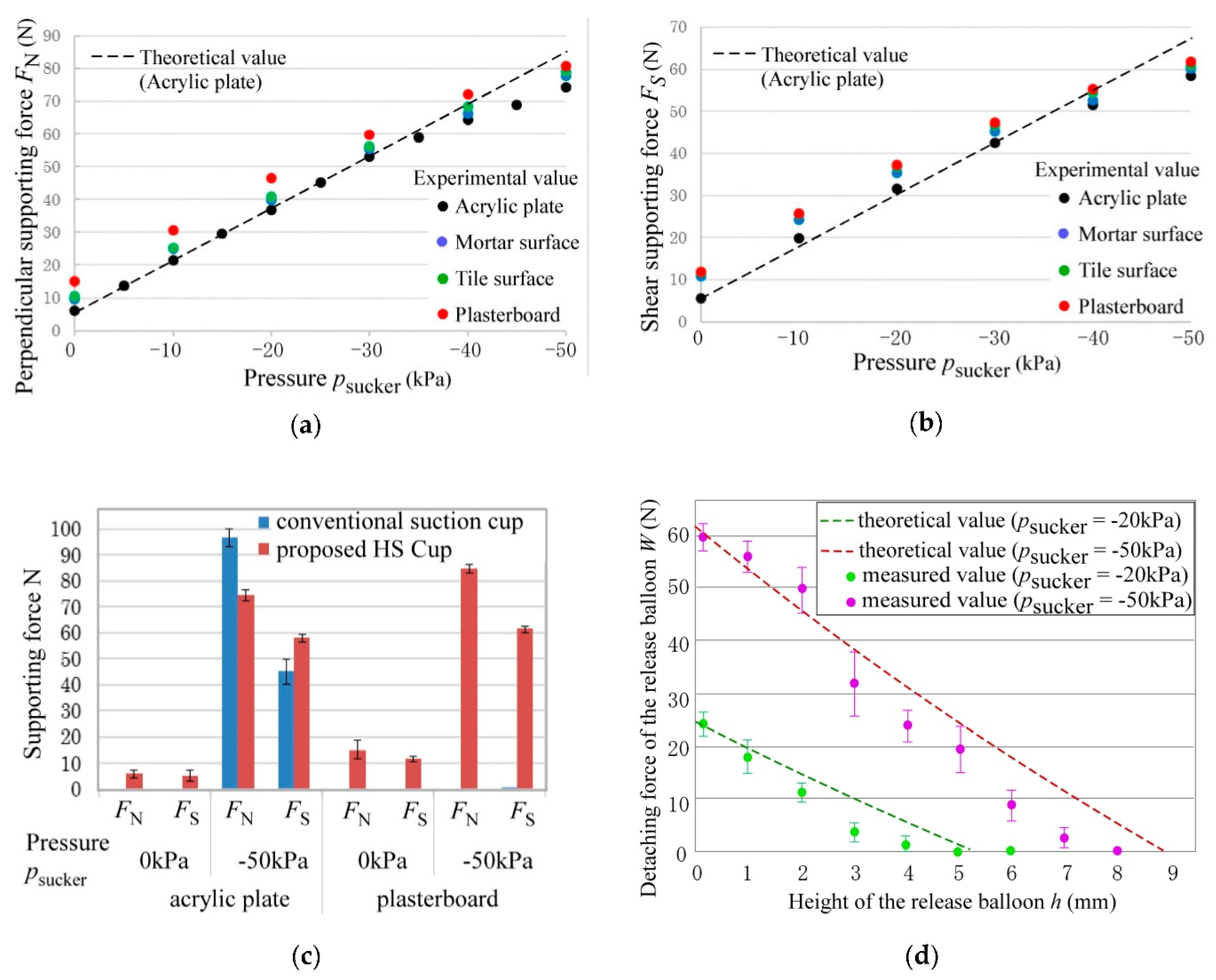
We conducted experiments using the prototype on four types of flat plates with different materials and surface roughness: an acrylic board, a mortar wall, a tile surface, and a plasterboard, as shown in Figure 6. The mortar wall had random irregularities. The tiled wall had grooves 8 mm wide and 2 mm deep in the vertical and horizontal directions. The plasterboard had fine holes of 1 μm diameter. From the experimental results in Figure 7, we confirmed that the gel ring adhered to every wall before the HS cup was suctioned. We also confirmed that the supporting force in the vertical and shear directions increased monotonically as the absolute value of the negative pressure increased, as illustrated in Figure 7a,b. All of them tended to be approximately the same as the theoretical values. However, the experimental value tended to be smaller than the theoretical value as the absolute value of the negative pressure increased because the ring gel was pushed and deformed, shrinking the inner diameter. Note that these experimental data show the average value when measured three times. Overall, the difference was within 5% for all three times.
Figure 7c compares suction force between the conventional vacuum suction cup and the HS cup. Here, the conventional suction cup has the same shape and size as the holder used for the HS cup. When negative pressure was applied to the acrylic board, the suction force of the HS cup was smaller than that of the conventional suction cup because the pressure-receiving area on which negative pressure acts is reduced by the ring gel. However, for plasterboard, the HS cup exhibited better adsorption characteristics. This means that an object that cannot be suctioned by a conventional suction cup due to leakage can be prevented from leaking because the gel ring functions as a seal in the HS cup. We also confirmed that the suction force can be increased if the suction flow rate is larger than the leakage flow rate even if there are minute holes.
The experimental value of the detaching force by the release balloon showed characteristics similar to the theoretical value, as shown in Figure 7d. However, as the height of the balloon increased, the value tended to decrease away from the theoretical value because the restoring force of the balloon was considered as a linear tension spring in the theoretical value, but in reality, it showed non-linearity, in which the rate of increase in the restoring force increased as the height increased.
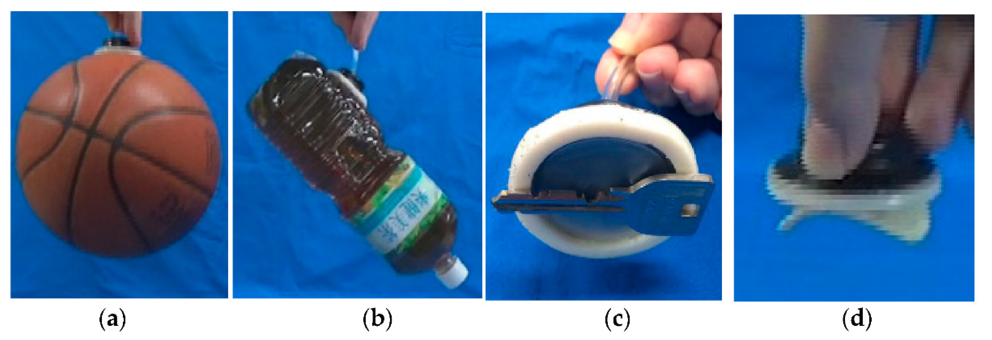
Using the HS cup, the operations of adsorption, lifting, and detachment were performed for four objects with different characteristics, as shown in Figure 8: (1) a basketball with a radius of curvature of 120 mm and a mass of 650 g, (2) a PET bottle with grooves 6 mm wide and 3 mm deep and a mass of 2 kg, (3) a key with an outer shape smaller than the contact surface of the suction cup and a thickness of 2 mm, and (4) a potato chip, which was fragile and had powder on its surface. All objects cannot be adsorbed by the conventional vacuum suction cup of the same size as the HS Cup. In (1) and (2), after adhering to the object with the gel ring, it was suctioned with negative pressure and lifted. Objects (3) and (4) could be lifted only by sticking to the gel ring. Furthermore, they were detached smoothly by the release balloon (Supplementary Movie S1).
3.3. Application to a Drone
Using a drone equipped with two HS cups, as shown in Table 1, we attempted to perch it from flight on the ceiling of gypsum board and the wall surface of mortar. AR.Drone 2.0 (Parrot, Paris, France) was used as the drone, and it was modified. One HS Cup for ceiling suction was placed at the center of the four propellers, and another for wall suction was placed at the center of the front surface. The size of the HS cup was the smallest that could support the drone’s own weight with just the adhesive strength of the gel ring. The pump and valve were the same as those described in Section 3.1. One pressure sensor (MPXA4250AC6U, Freescale Semiconductor, Austin, TX, USA) was installed in each suction cup to determine the suction state of the HS cups. At the time of suction, the gel ring adhered to the wall surface and then the inside of the release balloon was suctioned by a pump. When the pressure became negative, we judged the HS cup to be adsorbed to the wall, stopping the rotation of the propeller. At the time of desorption, the inside of the release balloon was pressurized while rotating the propeller to generate a drag force that was balanced with its own weight.
To increase the supporting force in the shear direction, the distance l in Equation (4) can be increased. Therefore, support legs were provided. The drone specifications are shown in Table 2, and the overall system configuration is shown in Figure 9.
The experiments were performed in two different environments, as illustrated in Figure 10: indoors with mortar walls and plasterboard ceilings (Supplementary Movie S2) and under concrete bridges (Supplementary Movie S1). In each case, the user operated while looking directly at the drone. A total of 5–7 s was required for the suction operation and 9–12 s for the detaching operation. In each case, we confirmed that the propeller was stopped at the time of adsorption and the drone could be supported by the HS cup. As a preparation just before detaching, the drone generated thrust to support its own weight to prevent from dropping if the suction force became zero. The reason that the aircraft shook immediately after the detachment was that the ring-shaped adhesive gel was partially adsorbed on the wall even after the detachment command. It is considered that this can be solved by arranging the balloon so as to surround the adhesive gel.
4. Discussion
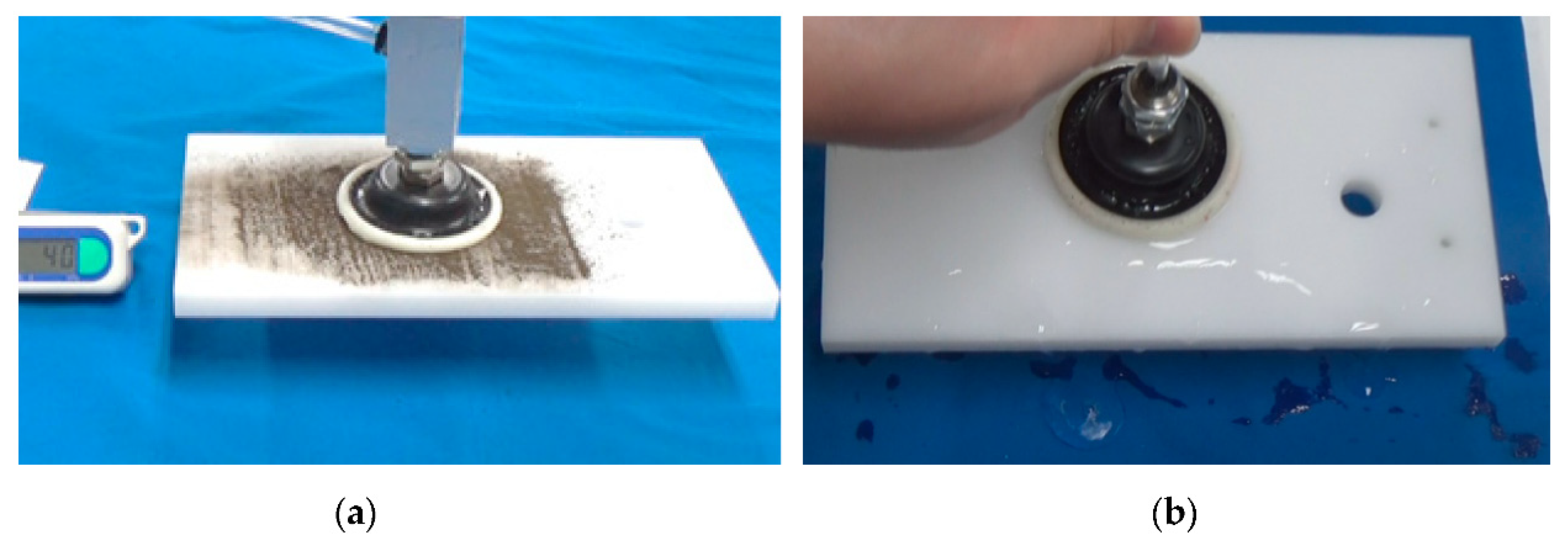
We confirmed that the gel ring used for the HS cup can adhere to objects that pose challenges for the conventional vacuum suction cup and can assist the adsorption. When the gel was adsorbed on an object with dust on the surface, the dust adhered to the surface of the gel, and the adsorption force deteriorated as the number of adsorptions increased. In an experiment in which a plastic plate covered with dust with a particle size of 4 μm to 1 mm was adsorbed with the HS cup, an adhesive force of about 2 N was generated up to the first three times (Figure 11a), but adsorbing was not achieved on the fourth attempt. However, when the dust adhering to the gel ring was wiped off with a sponge moistened with water from this state and left for about 5 min, the water in the gel ring evaporated. Then, when the same experiment as above was performed, the adhesive strength recovered to 1.8 N.
From the above experiments, we found that, even with dust, the HS cup can adsorb if it is equipped with a wiping function with a material with water and a function to dry the water immediately.
When trying to adsorb HS Cup on a plastic board wet with water, the gel ring alone could not adsorb it. However, when the inside was suctioned through the release balloon, it was suctioned and the plate could be lifted, as shown in Figure 11b. At this time, the gel ring functioned not as an adhesive but as a seal.
The adsorptive power of urethane gel ring deteriorates by about 40% one month after being left in the air. If you cover it to keep it dust-free, it will only deteriorate by about 5% even after a month. If washed with alcohol and dried, the adsorptive power will be restored to 98%.
5. Conclusions
To adsorb to various objects and environments, we constructed a new hybrid suction cup taking advantage of the adhesive force of the sticky gel of the ring shape and the suction force of negative pressure. Additionally, a release balloon with a check valve sheet was installed inside to enable the controlled detachment of the cup using positive pressure and to increase the adsorption force using negative pressure. Mathematical models of the adsorption and detaching forced and a manufacturing method were described. The effectiveness of the proposed method was verified through adsorption experiments on various objects and experiments in which the drone was anchored to a wall or ceiling. In the future, we will add a self-cleaning function to restore the adhesive strength after dust adheres to the gel surface.
Supplementary Materials
The following are available online at https://0-www-mdpi-com.brum.beds.ac.uk/2076-0825/10/3/50/s1, Video S1: actuators-10-00050-supplementary.
Author Contributions
Conceptualization, methodology, funding acquisition, supervision, project administration, funding acquisition, writing—original draft preparation, H.T.; software, designing, validation, investigation, Y.O. All authors have read and agreed to the published version of the manuscript.
Funding
This research was supported by JSPS KAKENSHI, grant number JP16H04296.
Conflicts of Interest
The authors declare no conflict of interest.
References
- Kovac, M.; Germann, J.; Hurzeler, C.; Siegwart, R.; Floreano, D. A perching mechanism for micro aerial vehicles. J. Micro-Nano Mechatron. 2009, 5, 77–91. [Google Scholar] [CrossRef] [Green Version]
- Kalantari, K.M.A. Autonomous perching and take-off on vertical walls for a quadrotor micro air vehicle. In Proceedings of the IEEE International Conference on Robotics and Automation (ICRA), Seattle, WA, USA, 26–30 May 2015; pp. 4669–4674. [Google Scholar]
- Daler, L.; Klaptocz, A.; Briod, A.; Sitti, M.; Floreano, D. A perching mechanism for flying robots using a fibre-based adhesive, in Robotics and Automation. In Proceedings of the (ICRA) IEEE International Conference, Karlsruhe, Germany, 6–10 May 2013; pp. 4433–4438. [Google Scholar]
- Doyle, C.; Bird, J.; Isom, T.; Kallman, J.; Bareiss, D.; Dunlop, D.; King, R.; Abbott, J.; Minor, M. An avian-inspired passive mechanism for quadrotor perching. IEEE/ASME Trans. Mechatron. 2013, 18, 506–517. [Google Scholar] [CrossRef]
- Jiang, H.; Pope, T.; Hawkes, W.; Christensen, L.; Estrada, A.; Parlier, A.; Tran, R.; Cutkosky, R.M. Modeling the dynamics of perching with opposed-grip mechanisms. In Proceedings of the IEEE International Conference on Robotics and Automation (ICRA), Hong Kong, China, 31 May–5 June 2014. [Google Scholar]
- Desbiens, L.; Asbeck, A.T.; Cutkosky, M.R. Landing, perching and taking off from vertical surfaces. Int. J. Robot. Res. 2011, 30, 355–370. [Google Scholar] [CrossRef]
- Mellinger, D.; Shomin, M.; Kumar, V. Control of quadrotors for robust perching and landing. In Proceedings of the International Powered Lift Conference, Philadelphia, PA, USA, 5–7 October 2010. [Google Scholar]
- Tsukagoshi, H.; Watanabe, M.; Hamada, T.; Ashlih, D.; Iizuka, R. Aerial Manipulator with Perching and Door-opening Capability. In Proceedings of the IEEE International Conference on Robotics and Automation (ICRA), Seattle, WA, USA, 26–30 May 2015; pp. 4663–4668. [Google Scholar]
- Hao, Y.; Biswas, S.; Hawkes, E.W.; Wang, T.; Zhu, M.; Wen, L.; Visell, Y. A Multimodal, Enveloping Soft Gripper: Shape Conformation, Bioinspired Adhesion, and Expansion-Driven Suction. IEEE Trans. Robot. 2020. [Google Scholar] [CrossRef]
- Shintake, J.; Rosset, S.; Schubert, B.; Floreano, D.; Shea, H. Versatile soft grippers with intrinsic electroadhesion based on multifunctional, polymer actuators. Adv. Mater. 2016, 28, 231–238. [Google Scholar] [CrossRef] [PubMed]
- Yuk, H.; Lin, S.; Ma, C.; Takaffoli, M.; Fang, N.X.; Zhao, X. Hydraulic hydrogel actuators and robots optically and sonically camouflaged in water. Nat. Commun. 2017, 8, 1–12. [Google Scholar] [CrossRef] [PubMed] [Green Version]
- Jiang, Y.; Chen, D.; Liu, C.; Li, J. Chain-like granular jamming: A novel stiffness-programmable mechanism for soft robotics. Soft Robot. 2019, 6, 118–132. [Google Scholar] [CrossRef] [PubMed]
- Amend, J.R.; Brown, E.; Rodenberg, N.; Jaeger, H.M.; Lipson, H. A positive pressure universal gripper based on the jamming of granular material. IEEE Trans. Robot. 2012, 28, 341–350. [Google Scholar] [CrossRef]
- Tramacere, F.; Beccai, L.; Mattioli, F.; Sinibaldi, E.; Mazzolai, B. Artificial adhesion mechanisms inspired by octopus suckers. In Proceedings of the International Conference on Robotics and Automation, St Paul, MN, USA, 14–19 May 2012; pp. 3846–3851. [Google Scholar] [CrossRef]
- Sandoval, J.A.; Jadhav, S.; Quan, H.; Deheyn, D.D.; Tolley, M.T. Reversible adhesion to rough surfaces both in and out of water, inspired by the clingfish suction disc. Bioinspir. Biomim. 2019, 14. [Google Scholar] [CrossRef] [PubMed]
- Wang, Y.; Yang, X.; Chen, Y.; Wainwright, D.K.; Kenaley, C.P.; Gong, Z.; Liu, Z.; Liu, H.; Guan, J.; Wang, T.; et al. A biorobotic adhesive disc for underwater hitchhiking inspired by the remora suckerfish. Sci. Robot. 2017, 2. [Google Scholar] [CrossRef] [PubMed] [Green Version]
- Glick, P.; Suresh, S.A.; Ruffatto, D.; Cutkosky, M., III; Tolley, M.T.; Parness, A. A Soft Robotic Gripper with Gecko-Inspired Adhesive. IEEE Robot. Autom. Lett. 2018, 3, 903–910. [Google Scholar] [CrossRef]
- Christensen, D.L.; Hawkes, E.W.; Suresh, S.A.; Ladenheim, K.; Cutkosky, M.R. μ tugs: Enabling microrobots to deliver macro forces with controllable adhesives. In Proceedings of the IEEE International Conference on Robotics and Automation, Washington State Convention Center, Seattle, WA, USA, 25–30 May 2015; pp. 4048–4055. [Google Scholar] [CrossRef]
- Autumn, K.; Dittmore, A.; Santos, D.; Spenko, M.; Cutkosky, M. Frictional adhesion: A new angle on gecko attachment. J. Exp. Biol. 2006, 209, 3569–3579. [Google Scholar] [CrossRef] [PubMed] [Green Version]
- Santos, D.; Spenko, M.; Parness, A.; Kim, S.; Cutkosky, M. Directional adhesion for climbing: Theoretical and practical considerations. J. Adhes. Sci. Technol. 2007, 21, 1317–1341. [Google Scholar] [CrossRef] [Green Version]
- Murphy, M.P.; Aksak, B.; Sitti, M. Gecko-inspired directional and controllable adhesion. Small 2009, 5, 170–175. [Google Scholar] [CrossRef] [PubMed]
- Gorb, S.; Varenberg, M.; Peressadko, A.; Tuma, J. Biomimetic mushroom-shaped fibrillar adhesive microstructure. J. R. Soc. Interface 2006, 4, 271–275. [Google Scholar] [CrossRef] [PubMed] [Green Version]
- Sameoto, D.; Ferguson, B. Robust large-area synthetic dry adhesives. J. Adhes. Sci. Technol. 2014, 28, 337–353. [Google Scholar] [CrossRef]
- Parness, A.; Soto, D.; Esparza, N.; Gravish, N.; Wilkinson, M.; Autumn, K.; Cutkosky, M. A microfabricated wedge-shaped adhesive array displaying gecko-like dynamic adhesion, directionality and long lifetime. J. R. Soc. Interface 2009, 6, 1223–1232. [Google Scholar] [CrossRef] [PubMed] [Green Version]
- Jeong, H.E.; Lee, J.-K.; Kim, H.N.; Moon, S.H.; Suh, K.Y. A nontransferring dry adhesive with hierarchical polymer nanohairs. Proc. Nat. Acad. Sci. USA 2009, 106, 5639–5644. [Google Scholar] [CrossRef] [PubMed] [Green Version]
- Prahlad, H.; Pelrine, R.; Stanford, S.; Marlow, J.; Kornbluh, R. Electroadhesive robots—Wall climbing robots enabled by a novel, robust, and electrically controllable adhesion technology. In Proceedings of the International Conference on Robotics and Automation, Nice, France, 22–26 September 2008; pp. 3028–3033. [Google Scholar] [CrossRef]
- Schaler, E.W.; Ruffatto, D.; Glick, P.; White, V.; Parness, A. An electrostatic gripper for flexible objects. In Proceedings of the. IEEE/RSJ International Conference on Intelligent Robots and Systems (IROS), Vancouver, BC, Canada, 24–28 September 2017; pp. 1172–1179. [Google Scholar] [CrossRef]
- Shen, W.; Gu, J.; Shen, Y. Permanent magnetic system design for the wall-climbing robot. Appl. Bionics Biomech. 2006, 3, 151–159. [Google Scholar] [CrossRef] [Green Version]
- Tsukagoshi, H.; Fuchigami, K.; Watari, E.; Kitagawa, A. Deformable Anchor Ball for Thrown Referring to Octopus Suckers. J. Robot. Mechatron. 2014, 26, 477–485. [Google Scholar] [CrossRef]
- Manabe, R.; Suzumori, K.; Wakimoto, S. Robot Skin with Integrated Micro Rubber Suction Cups Adhering Rough Surfaces. In Proceedings of the IEEE/RSJ International Conference on Intelligent Robots and Systems (IROS), Tokyo, Japan, 7 November 2013; pp. 4052–4057. [Google Scholar]
- Tsukagoshi, H.; Chiba, H.; Kitagawa, A. Gel-type Sticky Mobile Inspector to Traverse on the Rugged Wall and Ceiling. In Proceedings of the IEEE International Conference on Robotics and Automation, Kobe, Japan, 12–17 May 2009; pp. 1591–1592. [Google Scholar]
Figure 1.
Configuration and operating principle of the proposed hybrid suction cup (HS cup): (a) Side and bottom view of HS Cup; (b) working principle of two different modes; (c) configuration of the release balloon; (d) operating principle of the check valve sheet.
Figure 1.
Configuration and operating principle of the proposed hybrid suction cup (HS cup): (a) Side and bottom view of HS Cup; (b) working principle of two different modes; (c) configuration of the release balloon; (d) operating principle of the check valve sheet.

Figure 2.
Design parameters: (a) supporting force in the perpendicular and shearing determined by the sticky force of the gel ring and the suction force; (b) cross-sectional view of the release balloon in the unpressurized state; (c) cross-sectional view of the release balloon in the pressurized state.

Figure 3.
Fabrication process: (a) supporting force in the perpendicular and shearing determined by the sticky force of the gel ring and the suction force; (b) cross-sectional view of the release balloon in the unpressurized state; (c) combination of the gel ring and a release balloon to a holder.
Figure 3.
Fabrication process: (a) supporting force in the perpendicular and shearing determined by the sticky force of the gel ring and the suction force; (b) cross-sectional view of the release balloon in the unpressurized state; (c) combination of the gel ring and a release balloon to a holder.

Figure 4.
Developed prototype in two different modes: (a) side and bottom view of HS cup; (b) side and bottom view of the release balloon.
Figure 4.
Developed prototype in two different modes: (a) side and bottom view of HS cup; (b) side and bottom view of the release balloon.

Figure 5.
Pneumatic circuit to generate two different modes with a positive pressure pump: (a) suctioned mode; (b) detached mode.
Figure 5.
Pneumatic circuit to generate two different modes with a positive pressure pump: (a) suctioned mode; (b) detached mode.

Figure 6.
Four different planes used in the experiment: (a) acrylic board, (b) mortar wall, (c) tile surface, and (d) plasterboard, to examine the suctioned mode.
Figure 6.
Four different planes used in the experiment: (a) acrylic board, (b) mortar wall, (c) tile surface, and (d) plasterboard, to examine the suctioned mode.

Figure 7.
Comparison of experimental and theoretical values of the prototype: (a) perpendicular supporting force on 4 types of plates; (b) shear supporting force on 4 types of plates; (c) comparison of supporting force between the conventional suction cup and the HS cup; (d) detaching force of the release balloon. Regarding (c,d), the measurement of the experiment was performed three times, and the degree of dispersion is also shown in the graph.

Figure 8.
Photos of HS cup adsorbing and lifting the objects that conventional suction cups cannot handle: (a) a basketball; (b) a PET bottle containing 2 L of liquid; (c) a key; (d) a potato chip.
Figure 8.
Photos of HS cup adsorbing and lifting the objects that conventional suction cups cannot handle: (a) a basketball; (b) a PET bottle containing 2 L of liquid; (c) a key; (d) a potato chip.

Figure 9.
Drone with two HS cups: one for walls and one for ceilings. Support legs were installed to extend the moment of the supporting force by the HS cup when attached to a wall surface.
Figure 9.
Drone with two HS cups: one for walls and one for ceilings. Support legs were installed to extend the moment of the supporting force by the HS cup when attached to a wall surface.

Figure 10.
Experiment perching a drone in flight on the ceiling or wall with HS cups: (a) takeoff and landing in an indoor environment; (b) when detachment and adsorption are repeated on a concrete ceiling surface simulating a bridge.
Figure 10.
Experiment perching a drone in flight on the ceiling or wall with HS cups: (a) takeoff and landing in an indoor environment; (b) when detachment and adsorption are repeated on a concrete ceiling surface simulating a bridge.

Figure 11.
Experiment to confirm the possibility of adsorption of the HS Cup in harsh environments: (a) a plastic plate covered with dust can be adsorbed a few times; (b) a plastic plate covered with dust can be adsorbed a few times.
Figure 11.
Experiment to confirm the possibility of adsorption of the HS Cup in harsh environments: (a) a plastic plate covered with dust can be adsorbed a few times; (b) a plastic plate covered with dust can be adsorbed a few times.


Table 1.
The Parameters of the developed HS cup.
| Part | Parameter | Value |
|---|---|---|
| Gel ring | Outer diameter | 55 mm |
| Inner diameter | 45 mm | |
| Thickness | 5 mm | |
| Release balloon | Outer diameter | 44 mm |
| Thickness (min) | 0.7 mm | |
| Thickness (max) | 25 mm | |
| HS Cup | Weight | 18.8 g |
Table 2.
The specifications of the drone.
| Item | Value |
|---|---|
| Weight | 603 g |
| Flying time | 10 min |
| Size | 520 × 500 × 140 mm |
| Number of installed pumps | 1 |
| Number of installed valves | 3 |
Publisher’s Note: MDPI stays neutral with regard to jurisdictional claims in published maps and institutional affiliations. |
© 2021 by the authors. Licensee MDPI, Basel, Switzerland. This article is an open access article distributed under the terms and conditions of the Creative Commons Attribution (CC BY) license (http://creativecommons.org/licenses/by/4.0/).
Share and Cite
MDPI and ACS Style
Tsukagoshi, H.; Osada, Y. Soft Hybrid Suction Cup Capable of Sticking to Various Objects and Environments. Actuators 2021, 10, 50. https://0-doi-org.brum.beds.ac.uk/10.3390/act10030050
AMA Style
Tsukagoshi H, Osada Y. Soft Hybrid Suction Cup Capable of Sticking to Various Objects and Environments. Actuators. 2021; 10(3):50. https://0-doi-org.brum.beds.ac.uk/10.3390/act10030050
Chicago/Turabian StyleTsukagoshi, Hideyuki, and Yuichi Osada. 2021. "Soft Hybrid Suction Cup Capable of Sticking to Various Objects and Environments" Actuators 10, no. 3: 50. https://0-doi-org.brum.beds.ac.uk/10.3390/act10030050
Note that from the first issue of 2016, this journal uses article numbers instead of page numbers. See further details here.