
Parameter Identification of the Nonlinear Piezoelectric Shear d15 Coefficient of a Smart Composite Actuator


Department of Mechanical Engineering, California State University, Northridge, CA 91330, USA
*
Author to whom correspondence should be addressed.
Actuators 2021, 10(7), 168; https://0-doi-org.brum.beds.ac.uk/10.3390/act10070168
Submission received: 18 June 2021
/
Revised: 11 July 2021
/
Accepted: 16 July 2021
/
Published: 19 July 2021
(This article belongs to the Special Issue Ferroelectric Materials and Piezoelectric Actuators)
Abstract
:The objective of this work is to characterize the nonlinear dependence of the piezoelectric shear coefficient of a composite actuator on the static electric field and include this effect in finite element (FE) simulations. The Levenberg-Marquardt nonlinear least squares optimization algorithm implemented in MATLAB was applied to acquire the piezoelectric shear coefficient parameters. The nonlinear piezoelectric d15 shear constant of the composite actuator integrated with piezoceramic patches was obtained to be 732 pC/N at 198 V. The experimental benchmark was simulated using a three-dimensional piezoelectric FE model by taking piezoelectric nonlinearity into consideration. The results revealed that the piezoelectric shear coefficient increased nonlinearly under static applied electric fields over 0.5 kV/cm. A comparison between the generated transverse deflections of the linear and nonlinear FE models was also performed.
1. Introduction
shear-mode piezoceramics have stronger electromechanical properties than d31 or d33 modes [1,2], and they show nonlinear piezoelectric behavior due to domain wall motion [3]. The piezoelectric shear strain is boosted by the non-180° domain wall motion [3,4,5,6]. The piezoelectric shear response shows linear behavior until a threshold electric field value is achieved, which matches the potential energy barrier of the non-180° domain walls [3,4,5,6,7,8,9,10,11,12,13,14,15,16]. If the applied electric field exceeds this limiting value, the non-180° domain walls are induced dynamically, and the piezoelectric material reveals nonlinearity [6,7]. It was reported that shear-mode piezoelectric ceramics undergo significantly larger piezoelectric nonlinearity than d31 mode piezoceramics [3,6,7,8,11,12,13]. Piezoelectricity is the main source of nonlinearity in shear actuators under static electric fields. Piezoelectric thickness-shear mode actuators can control thickness shear-mode vibrations more effectively since they induce different deflection patterns than surface-mounted d33 and d31 actuators. Embedded piezoelectric shear actuators experience less damage and smaller stresses compared to surface-mounted extension actuators. In addition, they can also be applied in special configurations to prevent or control torsional deformation in engineering structures [3].
Mueller, Zhang, and Beige [14,15] studied the nonlinear shear piezoelectric response of lead zirconate titanate (PZT) piezoceramics under AC electric fields and expressed the experimental data using power fit equations. Berik et al. [3,16] investigated the piezoelectric nonlinearity in shear-mode lead-free hard piezoceramic 0.93 (Na0.5Bi0.5TiO3)-0. 07BaTiO3 (NBT-BT-Mn) material and d36 shear-mode piezoelectric BZT-BCT lead-free single crystals. Benjeddou [17,18] provided multidisciplinary reviews on shear-mode piezoceramics and field-dependent nonlinear piezoelectricity. Malakooti and Sodano [4,5] investigated the nonlinearity in the piezoelectric shear response of a single soft piezoceramic plate by applying bipolar and unipolar harmonic triangular electric fields under dynamic operational conditions. Hagiwara et al. [8] studied the nonlinear shear response in (K,Na)NbO3-based lead-free piezoceramics at a high frequency of 150 kHz. Trindade and Kakazu [19] presented some theoretical results on the application of the piezoelectric nonlinear effect in shear actuation of sandwich beams; however, experimental analysis was not performed in their study, and the piezoelectric coefficients used in the FE analysis were taken from Mueller and Zhang’s work [14], which was conducted under AC electric fields.
This paper presents an optimization method for nonlinear piezoelectric material parameter estimation in shear-mode composite actuators. The piezoelectric parameters were retrieved from the experimental data to characterize the nonlinear piezoelectric shear coefficient of a smart composite. The least squares optimization algorithm in MATLAB was applied to determine the piezoelectric material parameters. The nonlinear responses in the finite element simulations were obtained by including the parameters of the nonlinear piezoelectric coefficients. Following on previous work of the authors on piezoceramic shear-induced composite actuators [20], the present paper especially contributes to the investigation of piezoelectric shear coefficient using the least squares optimization algorithm. An analysis of the nonlinearity of shear-mode piezoelectric composite actuators is crucial for their design because shear-mode actuators are often integrated with composite structures in various engineering applications. The rest of the paper is organized as follows: Section 2 presents the technique used to estimate the piezoelectric shear coefficient, then Section 3 focuses on the nonlinear finite element simulation. Conclusions are summarized in Section 4.
2. Estimation of Parameters of Piezoelectric Shear Coefficient
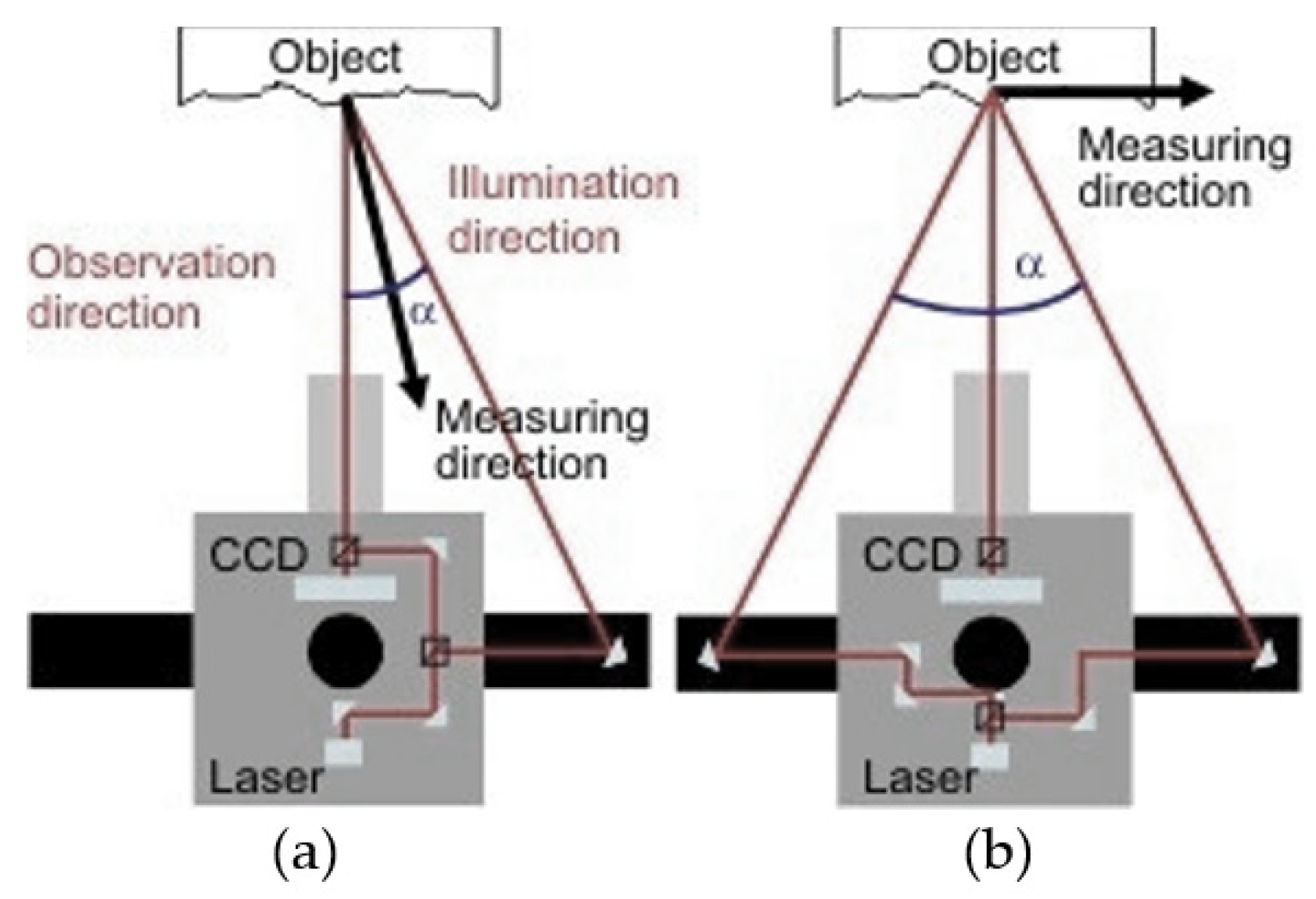
2.1. ESPI Measurements
To investigate the piezoelectric shear response under static electric field, an ESPI system (Dantec-Ettemeyer ESPI Q300) with in-plane and out-of-plane measurement configurations was used (Figure 1). The two-stack and four-stack piezoceramic benchmarks were constructed according to the design presented in Figure 2. Soft piezoceramic PIC255 shear patches of dimensions 25 × 25 × 0.5 mm3 were supplied from PI (Munich, Germany). The material properties of the piezoceramic material are provided in Table A1, Appendix A. The outer surfaces of the shear patches are covered with thin-film Au electrodes.
Piezoelectric shear constants were extracted from the detected shear-induced length displacements of the piezoceramic single and stack benchmarks and out-of-plane transverse deflections of a cantilevered smart composite structure (Figure 2). The other setup equipment included was a high-voltage (HV) amplifier model T-502, a laboratory power supply type EA 3016, and an ISTRA data processing software for the control and evaluation of the ESPI system.
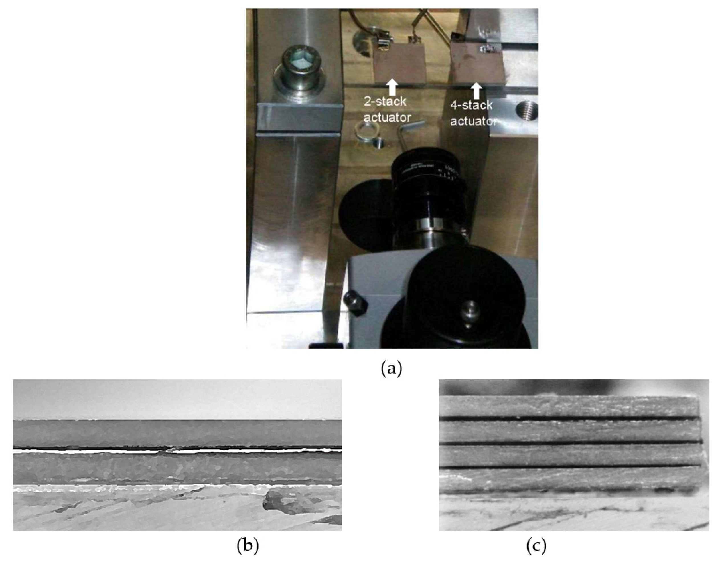
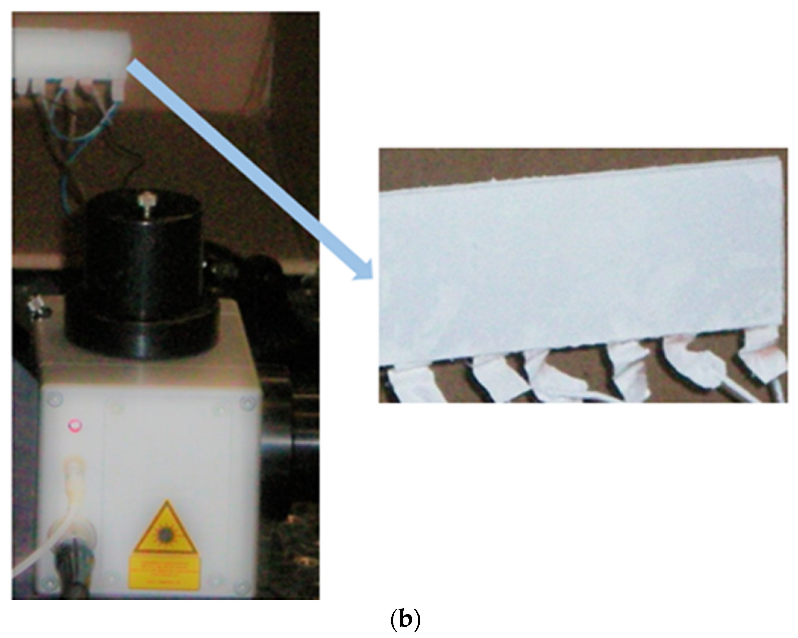
Figure 3 shows photographs of the experimental assembly and corresponding cross-sectional views.
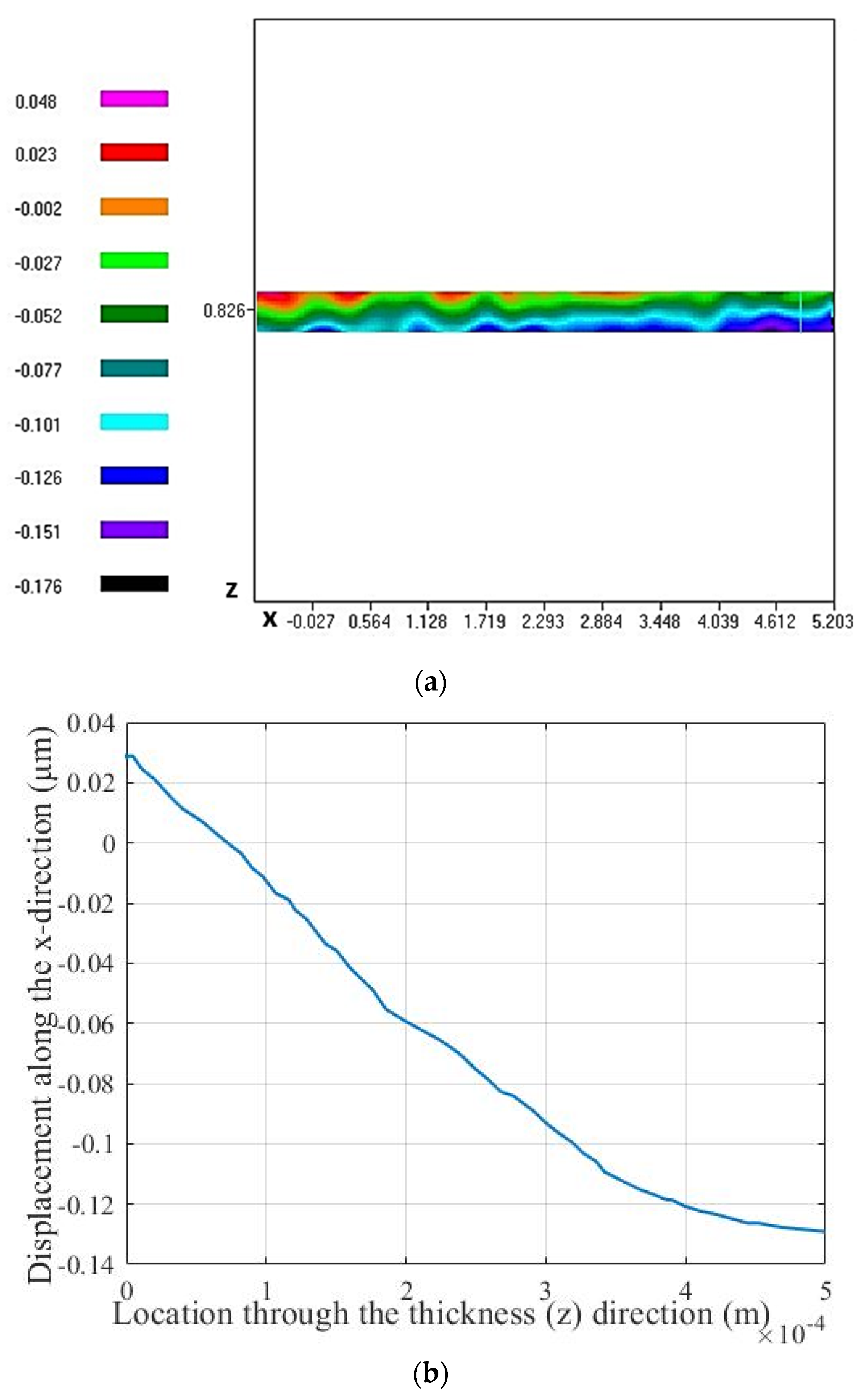
At the first step, the piezoelectric shear constant was evaluated in single and stack actuator configurations in order to obtain its original value at high applied voltages prior to integration in the composite structure. Stack design was selected for the piezoelectric stack actuator since it produces enhanced displacements that can be more accurately measured by the ESPI system depending on the number of layers and applied voltage. Since the shear-induced length (x-direction) displacements of the stack actuators at low applied voltages were not detected well by the ESPI system, measurements were performed at 199 V as the highest limiting voltage. The detected x displacements of the single, two-stack, and four-stack actuators under an applied voltage of 199 V (3.98 kV/cm) are presented in Figure 4.
The piezoelectric shear constant was extracted from measured length displacements using Equation (1) [21,22,23], and its values are presented in Table 1.
where D represents the measured displacement along the x-direction, V is the applied voltage, and n is the number of the piezoceramic layers in the stack actuator.
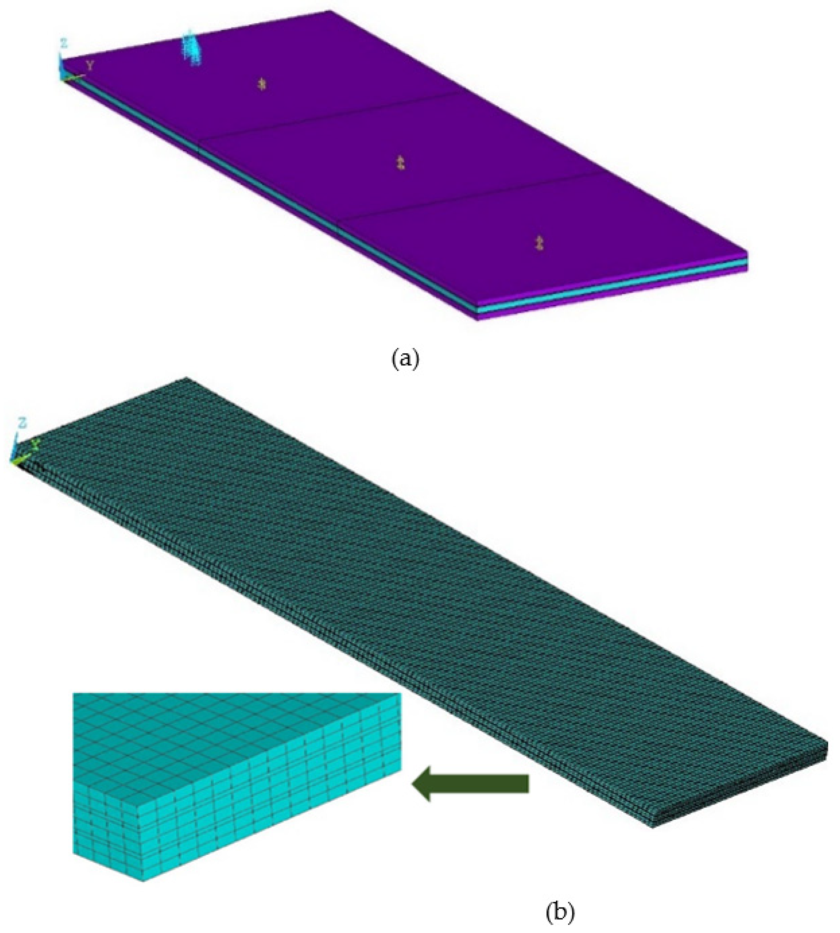
It should be noted that different benchmarks were used in the three cases listed in Table 1. Since the adhesive layers have a significant effect on the generated output, it is common to obtain slightly different coefficients from different benchmarks. Figure 5a,b shows the schematic and the experimental model of the composite benchmark. Out-of-plane deflections of the smart composite structure were measured using an electronic speckle pattern interferometry (ESPI system) (Dantec-Ettemeyer ESPI Q300). Soft piezoceramic PIC255 shear patches of dimensions 25 × 25 × 0.5 mm3 were supplied from PI Germany. Polyspeed G-EV 760 R glass fiber/epoxy layers with 0.49 mm thickness from Hexcel Austria were used as the sandwiching face layers. The material properties of the piezoceramic, glass/fiber epoxy, and adhesive materials are provided in Appendix A. The experimental benchmark used in the data extraction was in 75 mm length. The face layers of the benchmark were white-coated so that the speckles occurring during the applied voltage could be better detected. The benchmark was clamped to a holder and cantilevered. A detailed description of the experimental procedure can be found in the author’s previous work [20].
Piezoelectric transverse shear is obtained by applying an electric field perpendicular to the polarization direction of the material. The piezoelectric constitutive equation of the transverse shear strain γxz in terms of the applied electric field Ez and the piezoelectric shear strain coefficient is expressed as:
2.2. Parameter Identification of Piezoelectric Shear Coefficient
Mueller and Beige [14] proposed that the nonlinear piezoelectric shear response in soft piezoceramics can be expressed by power fit equation at applied electric fields above the threshold as:
where is the linear piezoelectric shear coefficient, E is the applied electric field, and piezoelectric nonlinearities of soft piezoceramics above the threshold field can be described by the additional coefficients and , which are to be computed from fitting measurement data.
Fitting the parameters to experimental data is an essential part of nonlinear modeling of piezoelectric response in shear-mode smart composites. Piezoelectric shear constants were extracted from the measured shear-induced transverse deflections of the cantilevered smart composite structure (Figure 5a,b) using least squares optimization algorithm in MATLAB. Function lsqcurvefit is particularly capable of fitting mathematical models to experimental data; for this reason, it was selected with the Levenberg–Marquardt algorithm to apply the least squares optimization method leading to the estimation of piezoelectric material parameters in this work. The top-level function lsqcurvefit enables fitting parameterized nonlinear functions to data by calling sub-level functions. It requires a user-defined function, the model equation, and an initial estimate for the parameters to be fitted. Choosing an initial guess of the variable parameters is crucial to reduce the risk of converging to incorrect parameters. The Levenberg-Marquardt algorithm (LMA) is an iterative optimization technique used to solve nonlinear least squares problems. Levenberg–Marquardt algorithm interpolates between gradient descent and Gauss–Newton methods at each iteration and updates the solution. LMA is used to conduct a curve fitting to measured data by minimizing the following expression:
yi are the collected data measured at points xi. The parameter φ is varied to minimize the error S(φ) of the function .
The extracted parameters of the piezoelectric shear strain coefficient (pC/N) at each applied electric field E (kV/cm) are expressed as:
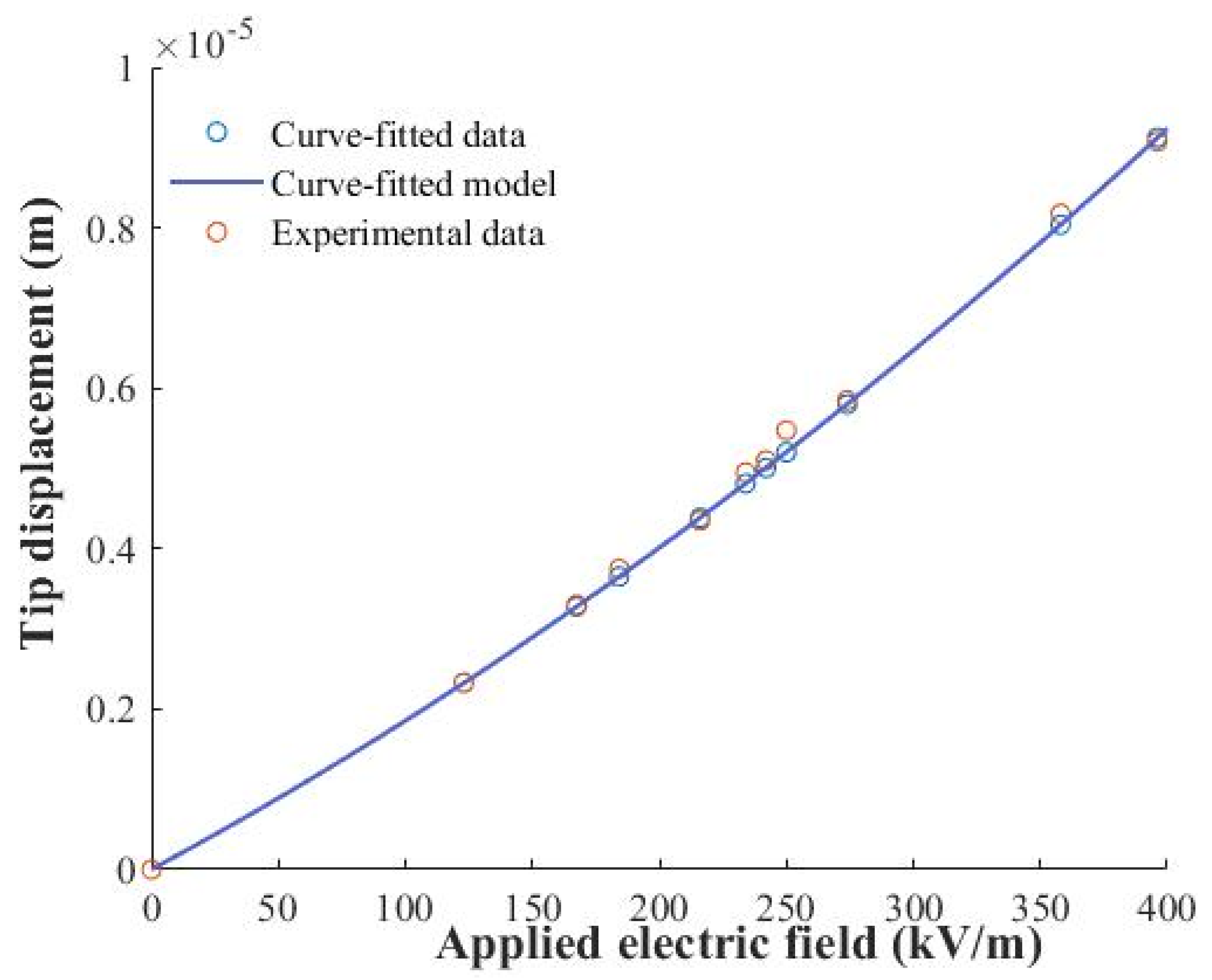
A comparison of the experimental and curve-fitted tip displacement values is presented in Figure 6. Equation (5) shows structural conformity with Equation (3) provided in [14]. The constant with a value of 732 pC/N at 198 V (3.96 kV/cm) showed 33% enhancement with respect to the linear value of 550 pC/N.
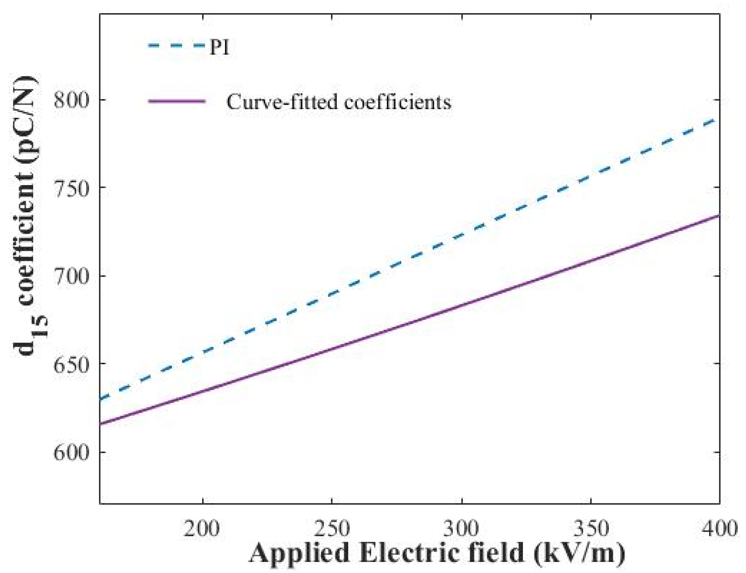
Measured and curve-fitted dependence of the piezoelectric shear coefficients of the composite actuator on the electric field and comparison to the values reported by the manufacturer (PI) [24] are shown in Figure 7. The comparison showed reasonable agreement. Since our benchmarks are different from PI’s, it is normal to obtain slightly different coefficients. Adhesive layers, boundary conditions, glass fiber/epoxy, and clamp also play significant roles in the generated output. A maximum difference of 7% happened at the highest applied electric field. According to the information provided by the manufacturer (PI), the experimental procedure applied by PI was as follows: the small signal values of were determined based on EN 50324-2, and the boundary condition was friction-resistant on one side and pseudo-floating bearing on the other. Inductive and capacitive sensors were used in measurements conducted by the manufacturer.
The measured and curve-fitted tip displacement values and extracted piezoelectric shear coefficients of the piezoelectric shear-mode composite actuator under different applied electric field values are presented in Table 2. As it can be seen, the results showed good agreement, with a maximum deviation percent of 1.93% at 3.58 kV/cm. The extracted values of the shear-mode composite actuator demonstrated reasonable agreement with the measured values of shear-mode stack actuators with a maximum error deviation percent of 6.97% at the highest applied voltage.
3. Finite Element (FE) Simulations Considering the Nonlinear Effect
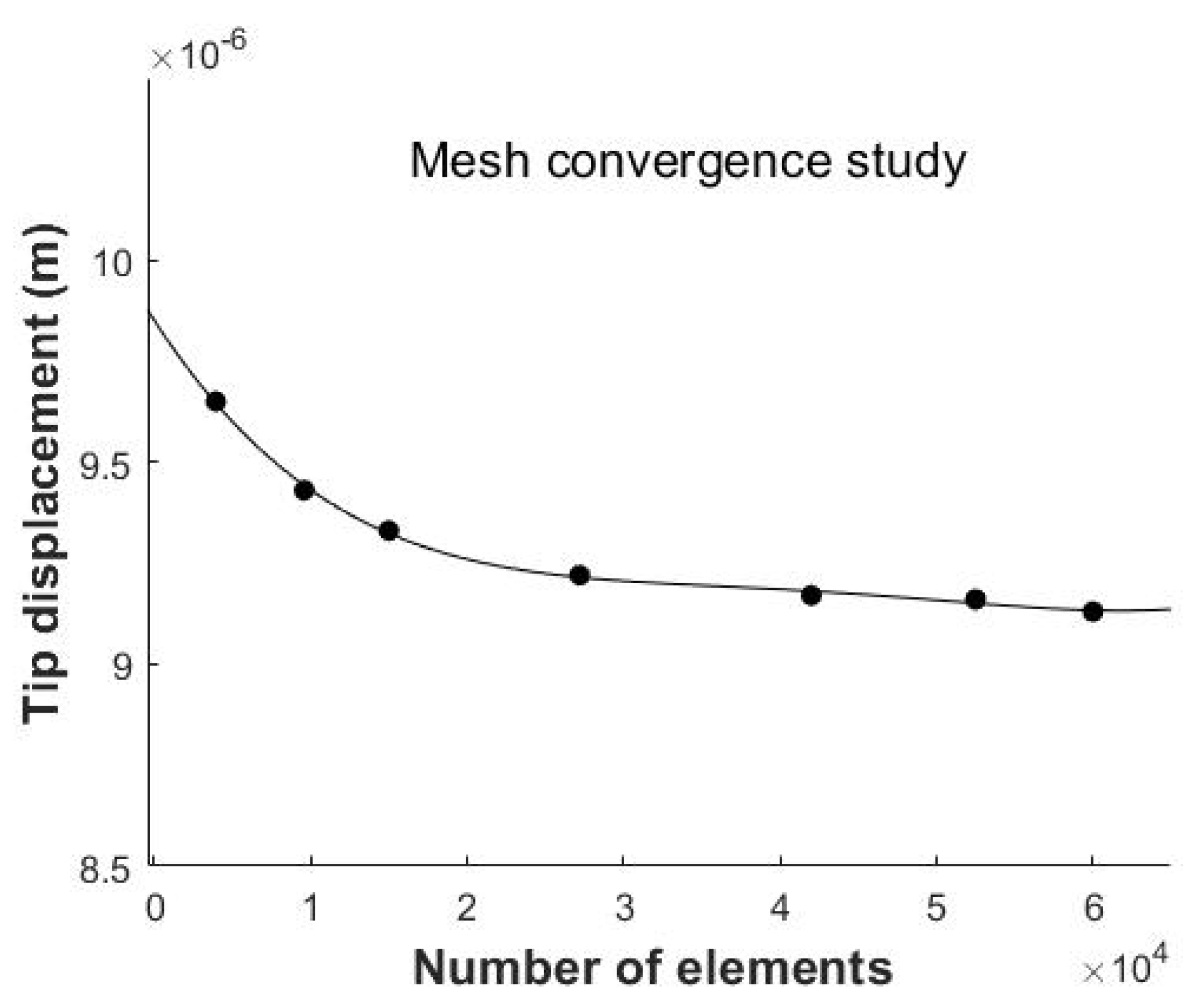
In this section, the piezoelectric nonlinear response of the shear-mode composite actuator (Figure 5) is simulated under different applied voltages using ANSYS© software (Figure 8). The previously developed linear model [20] is extended here by considering the nonlinear dependence of piezoelectric shear constant on the applied electric field and by taking the effect of 0.1 mm thick adhesives into consideration. The material properties used in the FE computations for the piezoceramic, glass/fiber epoxy, and adhesive materials are provided in Appendix A. Electromechanical material properties were obtained from the manufacturer (PI), and material properties of the glass fiber epoxy were experimentally measured as previously reported in [20]. To compute numerical responses considering the nonlinear effect, at each applied voltage, its corresponding nonlinear piezoelectric nonlinear shear coefficient, which was obtained from the experiment, was applied in the FE simulation. Piezoelectric and elastic quadratic hexahedral elements were used with in-plane mesh finite elements of size 0.5 mm. The number of through-the-thickness elements in the glass fiber/epoxy, adhesive, and piezoelectric core layers is 2, 1, and 2, respectively (Figure 8b). A tip displacement convergence analysis was performed to obtain a converged mesh (Figure 9). The mesh that was selected for the evaluation included 60,000 hexahedral elements and 267,717 nodes.
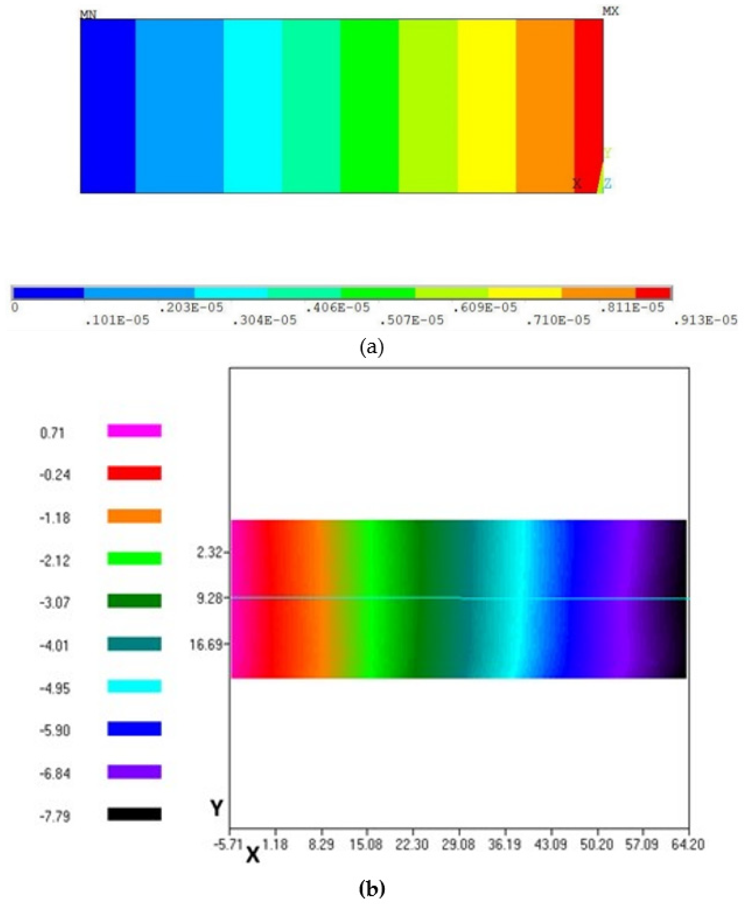
The surface distribution of the transverse shear deflection of the finite element simulation considering the nonlinearity and ESPI measurement at an applied voltage of 198 V are presented in Figure 10a,b.
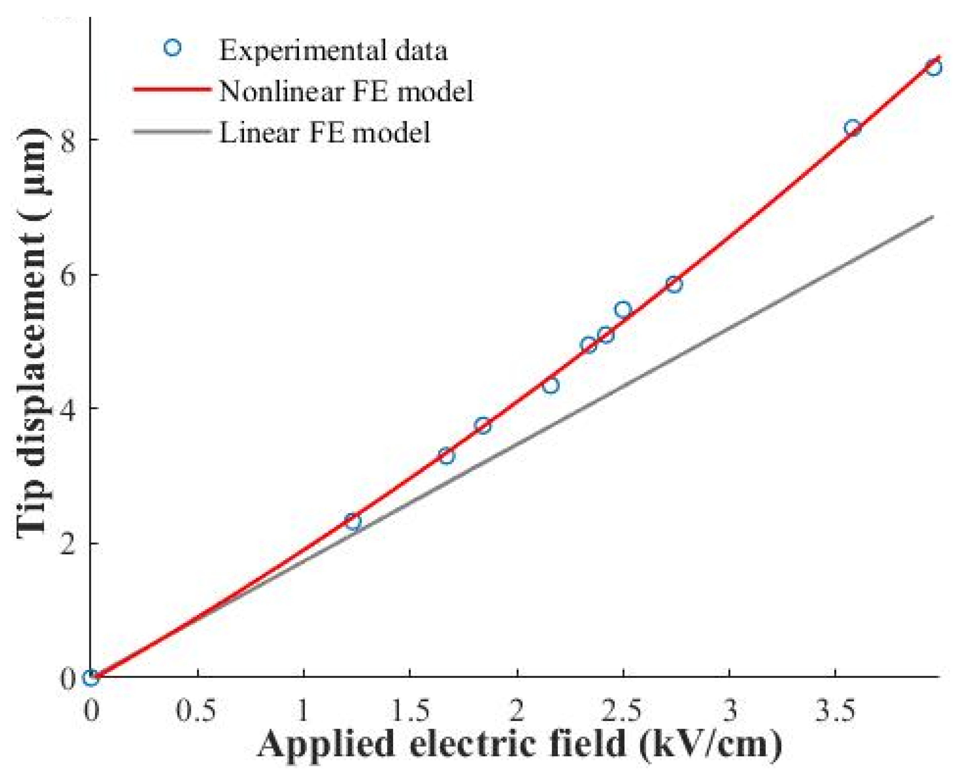
The generated tip displacements of the linear and nonlinear finite element simulations are presented in Figure 11, along with the experimental displacement values in Table 3. The finite element model with nonlinearity produced higher displacement values and showed a 33% increase at 198 V with respect to the linear model. The nonlinear effect starts to become significant at 0.5 kV/cm.
It can be observed that boosting the applied electric field results in an increased piezoelectric shear coefficient and the relative difference between the two models. These results reveal that piezoelectric nonlinearity cannot be ignored and should be considered in the design of shear-mode soft piezoceramic composite actuators because the real displacement can be much higher than the one anticipated by the linear finite element model.
4. Conclusions
In this work, the parameters of the nonlinear piezoelectric shear coefficient of a smart composite actuator were predicted using the least squares optimization technique. MATLAB lsqcurvefit function with Levenberg–Marquardt algorithm (LMA) was used for piezoelectric material parameter extraction of shear-mode composite actuator, implementing the least squares fitting. The piezoelectric shear constants of length shear-mode single and stack actuators and thickness shear-mode composite actuator demonstrated a reasonably acceptable correlation.
Nonlinear finite element simulations were conducted using piezoelectric shear coefficients extracted from the experiments. The findings disclosed that the nonlinear finite element model showed a 33% increase in displacement value at 198 V with respect to the linear model of this shear-mode lead-based PIC255 piezoceramic integrated composite actuator. It can be concluded that the inclusion of piezoelectric nonlinearity is a requirement in the realistic design of the shear-mode composite actuators.
Author Contributions
Conceptualization, P.B. and P.L.B.; methodology, P.B.; software, P.B.; validation, P.B.; formal analysis, P.B. and P.L.B.; investigation, P.B. and P.L.B.; resources, P.B. and P.L.B.; data curation, P.B.; writing—original draft preparation, P.B. and P.L.B.; writing—review and editing, P.B. and P.L.B.; visualization, P.B.; supervision, P.L.B.; project administration P.L.B. All authors have read and agreed to the published version of the manuscript.
Funding
This research received no external funding.
Institutional Review Board Statement
Not applicable.
Informed Consent Statement
Not applicable.
Data Availability Statement
Not applicable.
Acknowledgments
These experiments were performed at the Universität der Bundeswehr München in Germany. The authors also acknowledge the support of the department of mechanical engineering at California State University, Northridge (CSUN).
Conflicts of Interest
The authors declare no conflict of interest.
Appendix A

Table A1.
Material properties.
| Materials | Constants | Notations | Values |
|---|---|---|---|
| PIC255 (axially poled) | piezoelectric coupling stress constant (Cm−2) | e15 = e24 | 11.9 |
| e31= e32 | –7.15 | ||
| e33 | 13.7 | ||
| permittivity constants at constant strain (nFm−1) | 8.234 | ||
| 7.588 | |||
| Young’s moduli (GNm−2) | E2 = E3 | 62.89 | |
| E1 | 47.69 | ||
| Shear Moduli (GNm−2) | G13= G12 | 22.26 | |
| G23 | 23.15 | ||
| Poisson’s ratios | v13= v12 | 0.46 | |
| v23 | 0.36 | ||
| Density (kgm−3) | 7800 | ||
| Glass fiber/epoxy | Young’s moduli (GNm−2) | E2 = E3 | 13.1 |
| E1 | 33.11 | ||
| Shear Moduli (GNm−2) | G13= G12 | 3 | |
| G23 | 2.3 | ||
| Poisson’s ratios | v13= v12 | 0.27 | |
| v23 | 0.40 | ||
| Adhesive | Young’s modulus (GNm−2) | E | 1.03 |
| Poisson’s ratio | v | 0.37 |
References
- Altammar, H.; Dhingra, A.; Salowitz, N. Damage Detection Using d15 Piezoelectric Sensors in a Laminate Beam Undergoing Three-Point Bending. Actuators 2019, 8, 70. [Google Scholar] [CrossRef] [Green Version]
- Niu, J.; Wu, J.; Liu, Q.; Chen, L.; Guo, S.A. Dumbbell Shaped Piezoelectric Motor Driven by the First-Order Torsional and the First-Order Flexural Vibrations. Actuators 2020, 9, 124. [Google Scholar] [CrossRef]
- Berik, P.; Maurya, D.; Kumar, P.; Kang, M.G.; Priya, S. Enhanced torsional actuation and stress coupling in Mn-modified 0.93(Na0.5Bi0.5TiO3)-0.07BaTiO3 lead-free piezoceramic system. Sci. Technol. Adv. Mater. 2017, 18, 51–59. [Google Scholar] [CrossRef] [PubMed] [Green Version]
- Malakooti, M.H.; Sodano, H.A. Electromechanical characterization of piezoelectric shear actuators. In Proceedings of the ASME Conference on Smart Materials, Adaptive Structures and Intelligent Systems, Snowbird, UT, USA, 16–18 September 2013. [Google Scholar] [CrossRef]
- Malakooti, M.H.; Sodano, H.A.J. Direct measurement of piezoelectric shear coefficient. Appl. Phys. 2013, 113, 214106. [Google Scholar] [CrossRef]
- Hagiwara, M.; Takahashi, S.; Hoshina, T.; Takeda, H.; Sakurai, O.; Tsurumi, T. Nonlinear shear response in (K,Na)NbO3-based lead-free piezoelectric ceramics. Key Eng. Mater. 2010, 445, 47–50. [Google Scholar] [CrossRef]
- Li, S.; Cao, W.; Cross, L.E. The extrinsic nature of nonlinear behavior observed in lead zirconate titanate ferroelectric ceramic. J. Appl. Phys. 1991, 69, 7219–7224. [Google Scholar] [CrossRef] [Green Version]
- Hagiwara, M.; Hoshina, T.; Takeda, H.; Tsurumi, T. Nonlinear shear responses of lead zirconate titanate piezoelectric ceramics. Jpn. J. Appl. Phys. 2010, 49, 09MD04. [Google Scholar] [CrossRef]
- Berlincourt, D.A.; Curran, D.R.; Jaffe, H. Piezoelectric and Piezomagnetical Materials and Their Function in Transducers. Phys. Acoust. 1964, 1A, 169–270. [Google Scholar]
- Beigev, H.; Schmidtv, G. Electromechanical resonances for investigating linear and nonlinear properties of dielectrics. Ferroelectrics 1982, 41, 39–49. [Google Scholar] [CrossRef]
- Parashar, S.K.; DasGupta, A.; Wagner, U.; Hagedorn, P. Nonlinear shear vibrations of piezoceramic actuators. Int. J. Non-Linear Mech. 2005, 40, 429–443. [Google Scholar] [CrossRef]
- Parashar, S.K.; DasGupta, A.; Wagner, U.; Hagedorn, P. Investigation of nonlinear shear induced flexural vibrations of piezoceramic actuators. In Proceedings of the SPIE Smart Structures and Materials, San Diego, CA, USA, 26 July 2004; Volume 5383, pp. 71–81. [Google Scholar] [CrossRef]
- Parashar, S.K.; DasGupta, A.; Wagner, U.; Hagedorn, P. A modified Timoshenko beam theory for nonlinear shear-induced flexural vibrations of piezoceramic continua. Nonlinear Dyn. 2004, 37, 181–205. [Google Scholar] [CrossRef]
- Mueller, V.; Zhang, Q.M. Shear response of lead zirconate titanate piezoceramics. J. Appl. Phys. 1998, 83, 3754–3761. [Google Scholar] [CrossRef]
- Mueller, V.; Beige, H. Nonlinearity of soft PZT piezoceramic for shear and torsional actuator applications. In Proceedings of the ISAF 1998. Proceedings of the Eleventh IEEE International Symposium on Applications of Ferroelectrics (Cat.No.98CH36245), Montreux, Switzerland, 24–27 August 1998; pp. 459–462. [Google Scholar] [CrossRef]
- Berik, P.; Chang, W.; Jiang, X. Piezoelectric d36 in-plane shear-mode of lead-free BZT-BCT single crystals for torsion actuation. Appl. Phys. Lett. 2017, 110, 052902. [Google Scholar] [CrossRef]
- Benjeddou, A. Shear-Mode Piezoceramic Advanced Materials and Structures: A State of the Art. Mech. Adv. Mater. Struct. 2007, 14, 263–275. [Google Scholar] [CrossRef]
- Benjeddou, A. Field-dependent nonlinear piezoelectricity: A focused review. Int. J. Smart Nano Mater. 2018, 9, 68–84. [Google Scholar] [CrossRef] [Green Version]
- Trindade, M.A.; Kakazu, T.Y. Structural control of sandwich beams using shear piezoelectric actuators subjected to large electric fields. In Proceedings of the Conference IV Congresso Nacional de Engenharia Mecânica, Recife, Brazil, 20–25 August 2006. [Google Scholar]
- Berik, P.; Benjeddou, A. Static experimentations of the piezoceramic d15 shear actuation mechanism for sandwich structures with opposite or same poled patches-assembled core and composite faces. Int. J. Smart Nano Mater. 2011, 2, 230–244. [Google Scholar] [CrossRef] [Green Version]
- Available online: https://www.piceramic.com/en/piezo-technology/properties-piezo-actuators/displacement-modes/ (accessed on 30 June 2021).
- Available online: https://www.thorlabs.com/NewGroupPage9_PF.cfm?Guide=10&Category_ID=220&ObjectGroup_ID=5030 (accessed on 30 June 2021).
- Gao, X.; Xin, X.; Wu, J.; Chu, Z.; Dong, S. A multilayered cylindrical piezoelectric shear actuator operating in shear (d15) mode. Appl. Phys. Lett. 2018, 112, 152902. [Google Scholar] [CrossRef] [Green Version]
- Available online: https://static.piceramic.com/fileadmin/user_upload/pi_ceramic/files/catalog_CAT/PI_CAT128E_R3_Piezoelectric_Actuators.pdf (accessed on 30 June 2021).
Figure 1.
ESPI setup for (a) out-of-plane, (b) in-plane measurements.

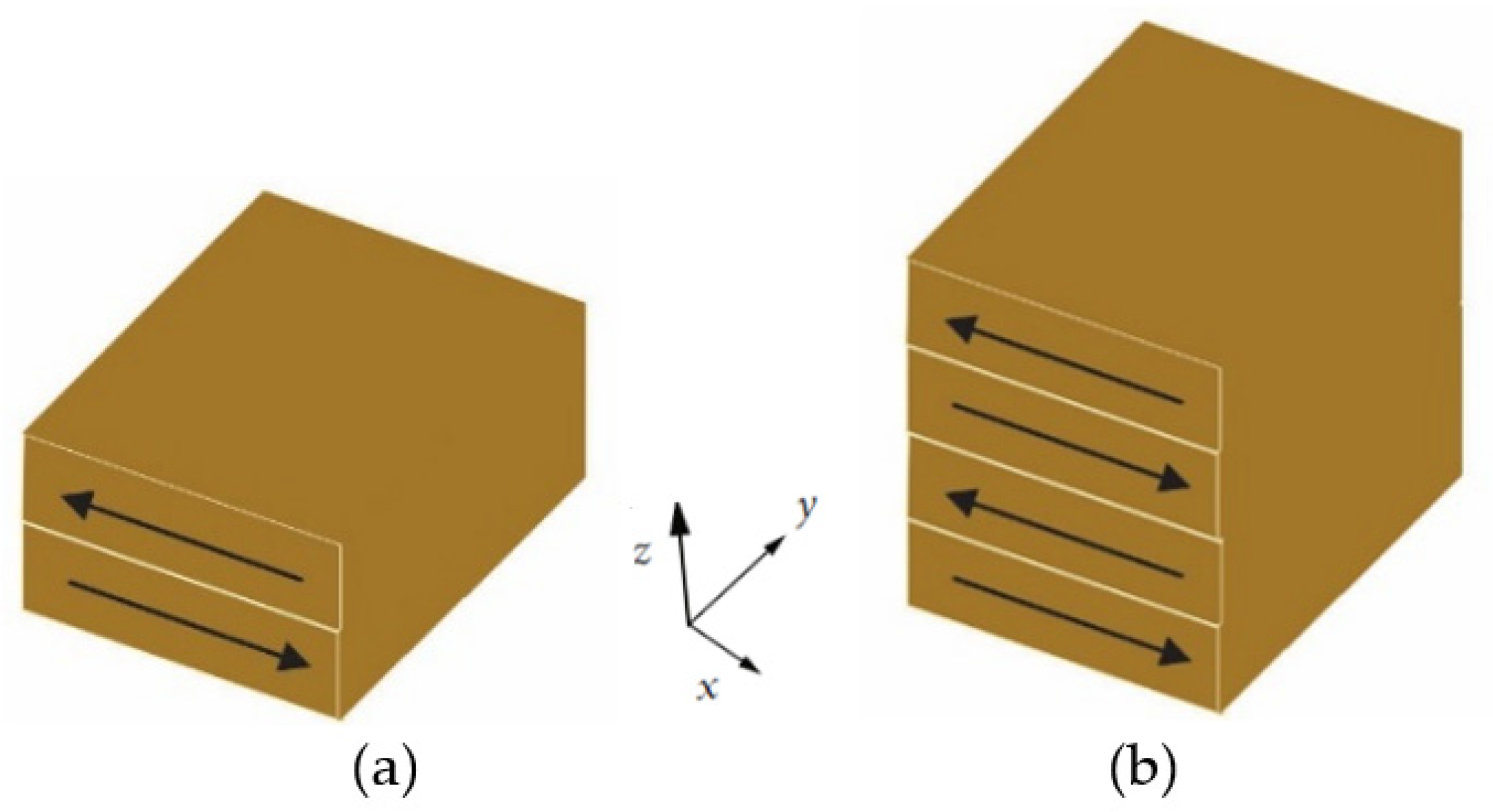
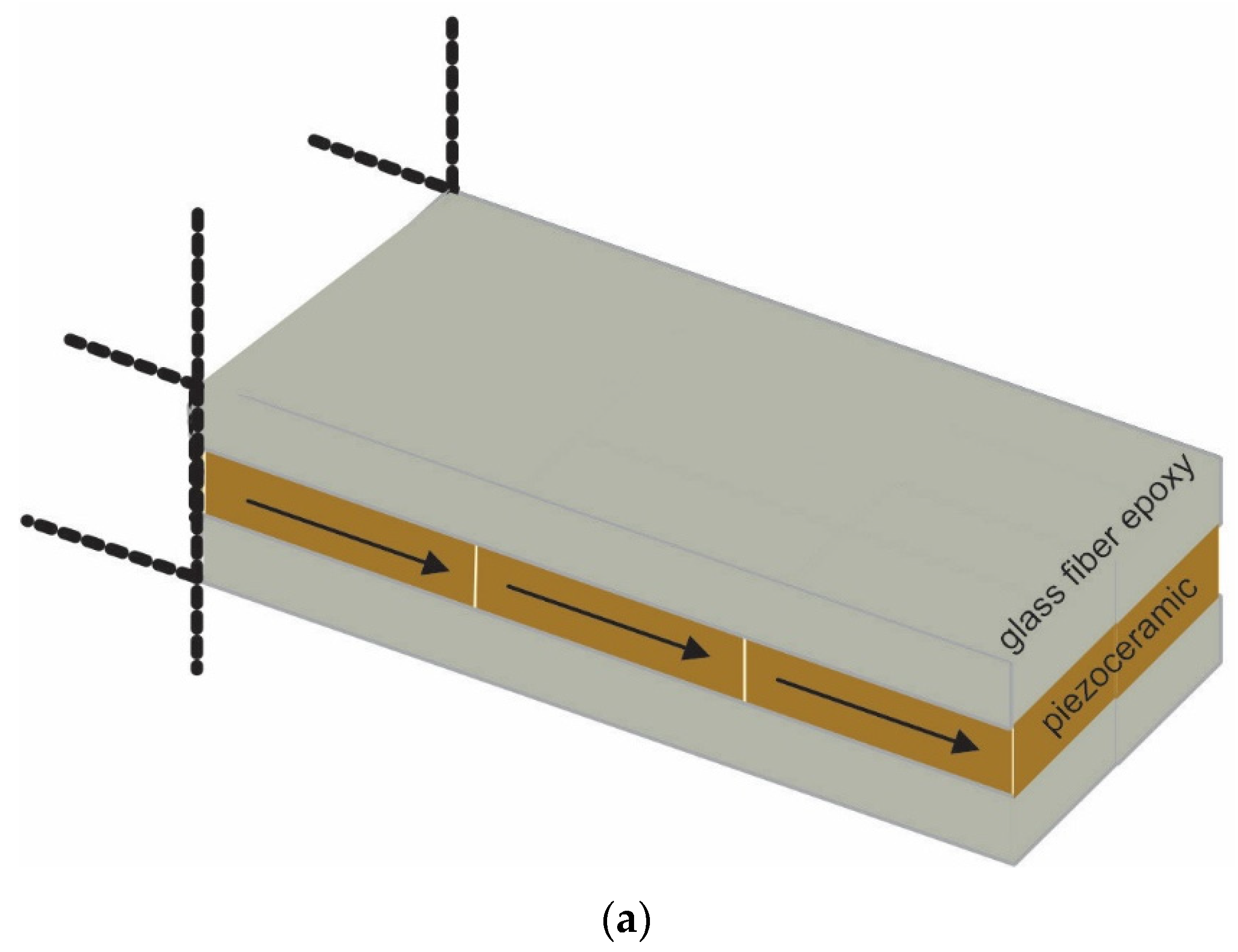
Figure 2.
Sketch of the (a) two-stack and (b) four-stack shear actuators.

Figure 3.
(a) Experimental assembly with two-stack and four-stack actuators, and cross-sectional views of (b) two-stack and (c) four-stack piezoceramic benchmarks.
Figure 3.
(a) Experimental assembly with two-stack and four-stack actuators, and cross-sectional views of (b) two-stack and (c) four-stack piezoceramic benchmarks.

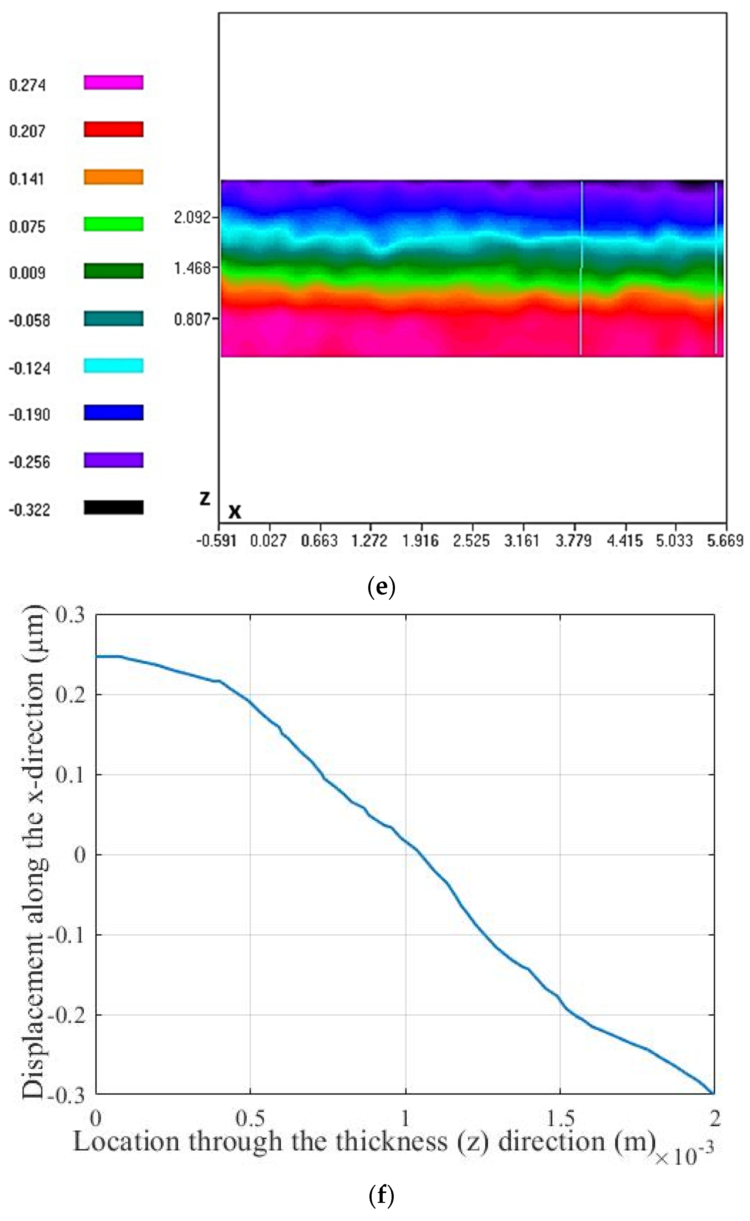
Figure 4.
x-direction displacement distributions and their variation through the thickness at the end of the actuator produced by single actuator (a,b), two-stack actuator (c,d), and four-stack actuator (e,f) under an applied voltage of 199 V.
Figure 4.
x-direction displacement distributions and their variation through the thickness at the end of the actuator produced by single actuator (a,b), two-stack actuator (c,d), and four-stack actuator (e,f) under an applied voltage of 199 V.


Figure 5.
(a) Schematic composite benchmark and (b) experimental model with zoomed view of the benchmark.
Figure 5.
(a) Schematic composite benchmark and (b) experimental model with zoomed view of the benchmark.


Figure 6.
Comparison of experimental and optimized tip displacement values.

Figure 7.
Dependence of piezoelectric shear constant on the applied electric field.

Figure 8.
(a) FE model and (b) full mesh with zoomed partial view.

Figure 9.
Tip displacement convergence plot.

Figure 10.
Transverse deflection surface distribution in (a) nonlinear FE simulation and its comparison to the (b) ESPI under applied voltage of 198 V.
Figure 10.
Transverse deflection surface distribution in (a) nonlinear FE simulation and its comparison to the (b) ESPI under applied voltage of 198 V.

Figure 11.
Comparison of linear and nonlinear FE models in terms of generated tip deflection versus applied electric field.
Figure 11.
Comparison of linear and nonlinear FE models in terms of generated tip deflection versus applied electric field.

Table 1.
Displacement D and constant values of length shear-mode stack actuators at 199 V (3.98 kV/cm) applied voltage.
Table 1.
Displacement D and constant values of length shear-mode stack actuators at 199 V (3.98 kV/cm) applied voltage.
| Type | D, Displacement (µm) | |
|---|---|---|
| 1 layer | 0.156 | 783 |
| 2-stack | 0.288 | 723 |
| 4-stack | 0.546 | 686 |
Table 2.
Displacement and values of thickness shear-mode composite actuator.
| Applied Electric Field (kV/cm) | Experimental Displacement (µm) | Curve-Fitted Displacement (µm) | Deviation Percentage (%) | |
|---|---|---|---|---|
| 3.96 | 9.080 | 9.106 | 0.286 | 732 |
| 3.58 | 8.180 | 8.022 | 1.931 | 713 |
| 2.74 | 5.850 | 5.789 | 1.043 | 672 |
Table 3.
Displacement and values of thickness shear-mode composite actuator.
| Applied Electric Field (kV/cm) | Experimental Displacement (µm) | FE (Nonlinear) Displacement (µm) | FE (Linear) Displacement (µm) |
|---|---|---|---|
| 3.96 | 9.080 | 9.130 | 6.860 |
| 3.58 | 8.180 | 8.033 | 6.202 |
| 2.74 | 5.850 | 5.782 | 4.747 |
Publisher’s Note: MDPI stays neutral with regard to jurisdictional claims in published maps and institutional affiliations. |
© 2021 by the authors. Licensee MDPI, Basel, Switzerland. This article is an open access article distributed under the terms and conditions of the Creative Commons Attribution (CC BY) license (https://creativecommons.org/licenses/by/4.0/).
Share and Cite
MDPI and ACS Style
Berik, P.; Bishay, P.L. Parameter Identification of the Nonlinear Piezoelectric Shear d15 Coefficient of a Smart Composite Actuator. Actuators 2021, 10, 168. https://0-doi-org.brum.beds.ac.uk/10.3390/act10070168
AMA Style
Berik P, Bishay PL. Parameter Identification of the Nonlinear Piezoelectric Shear d15 Coefficient of a Smart Composite Actuator. Actuators. 2021; 10(7):168. https://0-doi-org.brum.beds.ac.uk/10.3390/act10070168
Chicago/Turabian StyleBerik, Pelin, and Peter L. Bishay. 2021. "Parameter Identification of the Nonlinear Piezoelectric Shear d15 Coefficient of a Smart Composite Actuator" Actuators 10, no. 7: 168. https://0-doi-org.brum.beds.ac.uk/10.3390/act10070168
Note that from the first issue of 2016, this journal uses article numbers instead of page numbers. See further details here.