Parametric Modeling of a Long-Range Aircraft under Consideration of Engine-Wing Integration †


1
Department Loads Analysis and Aeroelastic Design, Institute of Aeroelasticity, German Aerospace Center (DLR), 37073 Göttingen, Germany
2
Department Aeroelastic Simulation, Institute of Aeroelasticity, German Aerospace Center (DLR), 37073 Göttingen, Germany
*
Author to whom correspondence should be addressed.
†
This paper is a revised version of our paper published at the German Aerospace Conference 2019.
Aerospace 2021, 8(1), 2; https://0-doi-org.brum.beds.ac.uk/10.3390/aerospace8010002
Submission received: 27 November 2020
/
Revised: 17 December 2020
/
Accepted: 18 December 2020
/
Published: 23 December 2020
(This article belongs to the Special Issue Aeroelasticity, Volume II)
Abstract
:The purpose of this paper is to investigate the influence of the engine position and mass as well as the pylon stiffness on the aeroelastic stability of a long-range wide-body transport aircraft. As reference configuration, DLR’s (German Aerospace Center/Deutsches Zentrum für Luft und Raumfahrt) generic aircraft configuration DLR-D250 is taken. The structural, mass, loads, and optimization models for the reference and a modified configuration with different engine and pylon parameters are set up using DLR’s automatized aeroelastic design process cpacs-MONA. At first, the cpacs-MONA process with its capabilities for parametric modeling of the complete aircraft and in particular the set-up of a generic elastic pylon model is unfolded. Then, the influence of the modified engine-wing parameters on the flight loads of the main wing is examined. The resulting loads are afterward used to structurally optimize the two configurations component wise. Finally, the results of post-cpacs-MONA flutter analyses performed for the two optimized aircraft configurations with the different engine and pylon characteristics are discussed. It is shown that the higher mass and the changed position of the engine slightly increased the flutter speed. Although the lowest flutter speeds for both configurations occur at a flutter phenomenon of the horizontal tail-plane outside of the aeroelastic stability envelope.
1. Introduction
For the development of new aircraft configurations, the obvious trend down to desired highly efficient aircraft can be observed in the recent past: The further development of existing aircraft configurations with local modifications seems more advantageous compared to the design of a completely new aircraft to achieve overall improvements. For example, rather than designing a completely new aircraft, performance improvements were achieved with aircraft that have been equipped with more efficient engines with a higher by-pass ratio [1]. Due to the higher by-pass ratio, the outer diameter of the engine nacelle increases. One possible approach to maintain the once fixed ground clearance for the bigger nacelle is to increase the length of the landing gear strut. Such a modification is very costly since an established landing gear has very limited geometrical margins regarding its stowage. Complicated and heavy strut shrinkage mechanisms may arise [2,3]. A reasonable way to mount a bigger engine under the wing and keep the required ground clearance and the fixed wing-fuselage attachment is to shift the engine more ahead of the wing in order to be able to shift it upwards. A heavier, larger and, therefore, higher and farther forward located engine has not only a high influence on the aerodynamic and structural side but also on the aeroelastic behavior, on the flight characteristics, the flight mechanics, and the flight dynamics of the aircraft.
The trend of an increasing engine diameter and the advancements of high-fidelity-based aerodynamic shape optimization techniques and its application to the engine integration is also a local field (see References [4,5]). The important investigation of the aerodynamic influence of the thrust-flow and its interaction with the flow of the main wing is not part of this publication.
Regarding the structural dynamics, Wang et al. [6] highlighted that wing-mounted engines have an effect on the natural eigenfrequency of a wing compared to a clean wing configuration without a mounted engine and consequently have a great impact on the flutter characteristics of the wing. The work of Wang et al. emphasizes the necessity of taking the inertia forces of the engine and the elasticity of the pylon into consideration when investigating a wing-engine system on flutter.
More recently, Latif et al. [7] presented a semi-analytical approach to perform flutter analysis of a high-aspect-ratio wing modeled as a cantilevered beam. Although the investigated configuration is an Unmanned Aerial Vehicle (UAV) without a wing-mounted engine, this study, furthermore, neglected the stiffness of the wing-fuselage attachment and does not capture the flutter responses of the tail planes as a wing-alone configuration was investigated.
The effect of the engine chord- and span-wise position on the wing regarding the aeroelastic stability of a single wing or a flying wing aircraft has been investigated in several publications [8,9,10]. They also incorporated a thrust vector acting on the engine center-of-gravity. In some of the cases, the thrust vector is formulated as a follower force to consider the coupling of the deflected thrust vector with the structural dynamic characteristics of the wing.
Jonsson et al. [11] developed and implemented a flutter constraint formulation suitable for gradient-based optimization processes for a wing-alone configuration. They performed a design space analysis and optimized the planform of an idealized wing using a multidisciplinary objective. A flat plate of a rectangular planform cantilevered at one edge was used as the structural representative of the wing rather than a complete aircraft with tail-plane and wing-mounted engines.
As the flutter characteristic of a complete aircraft configuration is not limited to one component, a thorough examination of the entire configuration and its flutter relevant characteristics is necessary. In Reference [12], Cavagna et al. presented the design framework NeoCASS, which enables aero-structural assessment of an aircraft design layout at the conceptual design stage. NeoCASS was furthermore used in Reference [13] to study the aeroelastic behavior of a complete aircraft configuration. By not incorporating a structural model of the pylon, the elasticity of the engine-wing integration was neglected as well.
Waitz et al. [14] investigated the structural interaction between large rotating engine masses and furthermore took the characteristics of the flexible engine–wing and wing–fuselage interaction into consideration. They incorporated both the whirl and the thrust effect into the equation of motion for a complete aircraft configuration. Gyroscopic or precession effects of a larger and heavier engine and the influence of the thrust have not been considered within this publication.
This work focuses on the structural dynamic characteristics and the aeroelastic stability of a complete aircraft configuration as a result of the mentioned modification regarding the engine–wing integration of a bigger and heavier engine. With the presented parametric modeling capability of the elastic pylon together with the structural and aerodynamic model of the tail-planes and the fuselage, the influence of the engine mass and location, the pylon, and the fuselage stiffness together with the structural dynamic behavior of the tail-planes can be considered while investigating the flutter characteristics of a complete aircraft configuration for a conventional long-range aircraft.
2. Materials, Methods, and Tools
2.1. Aircraft Configurations
For this paper, two different aircraft configurations are considered. The reference configuration called “baseline” and a “modified” configuration that has a bigger and heavier engine and an appropriate stiffer pylon. The cpacs-MONA process is first of all used to set up the structural, mass, loads, and optimization models for the baseline configuration. After changing a few parameters regarding the engine and pylon, cpacs-MONA is executed again to set up the simulation models for the modified configuration.
2.1.1. Reference Aircraft Configuration
As a reference configuration, DLR´s generic long-range wide-body transport aircraft, the so-called DLR-D250, is used [15,16]. The top-level aircraft requirements of the DLR-D250 configuration are similar to those of the Airbus A330-200. The first model of the Airbus A330-200 received its certification in March 1998. The model called A330-243 (certified in 1999) was equipped with two Rolls-Royce Trent 772B-60 turbofan engines [17]. This engine model has a by-pass ratio of about 5:1 and a maximum outer diameter of 2.74 m. Its dry-mass without fluids and nacelle is 6160 kg [18].
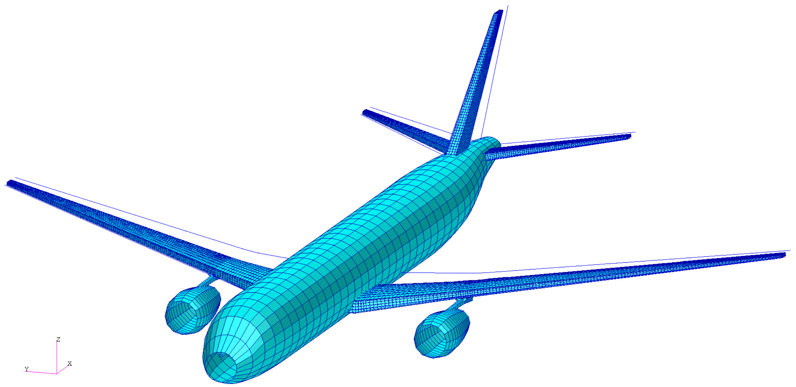
In Figure 1, the structural finite element model of the DLR-D250 configuration named global finite element model (GFEM)/Dynamic (output of cpacs-MONA) is shown. GFEM stands for global finite element model, and dynamic expresses the applicability of the model for structural dynamic analysis. The main characteristics of the DLR-D250 are listed in Table 1.
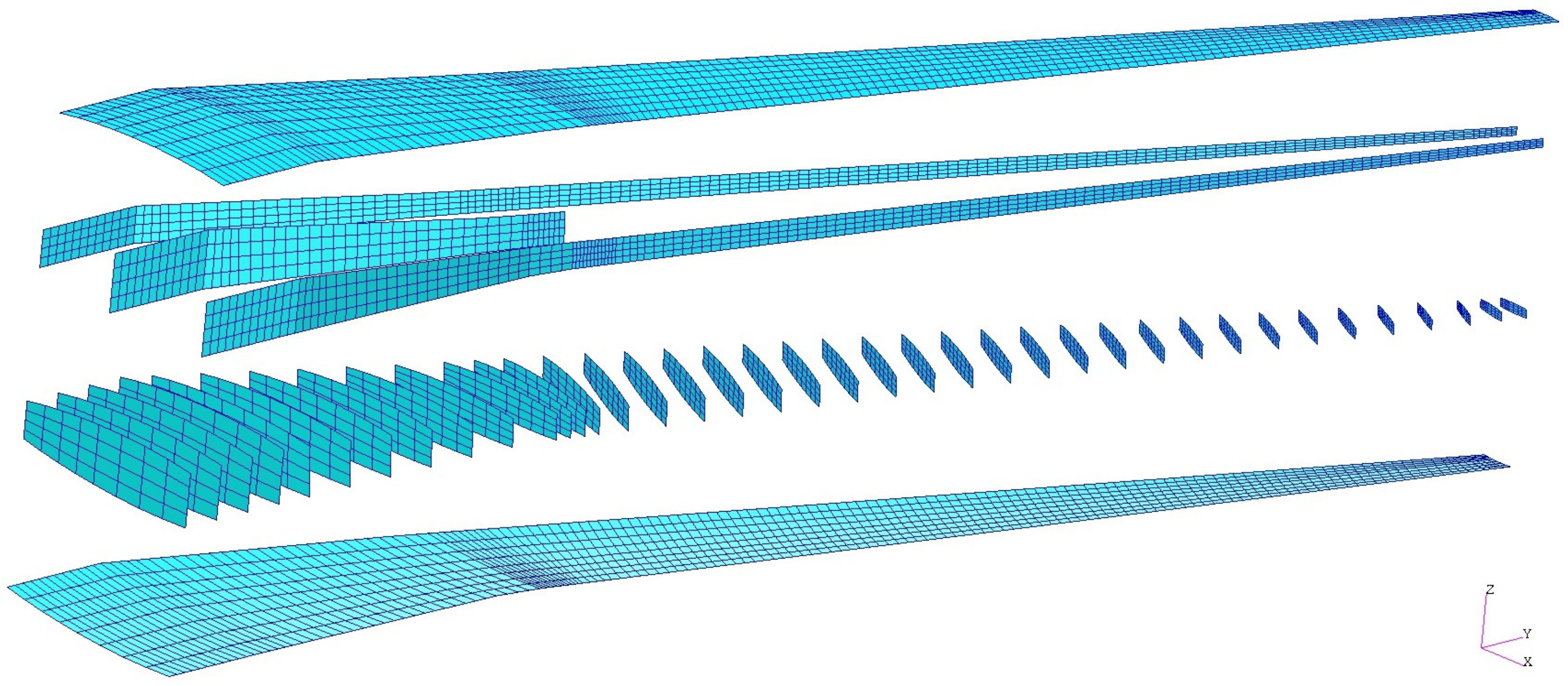
The structural topology of the wing-box is visualized in Figure 2 for the main wing of DLR-D250´s GFEM. The main load-carrying structural elements (ribs, spars, and skin covers) are pictured in an exploded view. The wing has a kink at the engine attachment location. The load-carrying structure of the wing model consists of 39 ribs and three spars, whereby the mid-spar ends at the kink. The first eleven ribs up to the kink are arranged streamwise. The ribs from the kink to the tip of the wing are aligned orthogonally to the front spar, while the tip-rib is positioned streamwise again. At the kink, the rib spacing is narrower compared to the rest of the wing. These additional ribs are introduced to spread loads of the engine at the pylon-wing attachment. The element partition can be seen in Figure 2 as well. The ribs are divided into sub-ribs by the mid-spar and the spars are divided into sub-spars by each rib. Each sub-rib and sub-spar is divided into four-by-four finite shell elements. The skin covers are partially divided by surrounded spars and ribs and equally divided into four-by-four finite shell elements. Modeling guidelines for the finite elements regarding aspect ratio, skew, and internal angles are, respectively, taken into consideration within the model set-up.
2.1.2. Modified Aircraft Configuration
The latest development of the A330 is colloquially called A330neo (new engine option). This aircraft has been certified under the model name A330-841 in July 2014. The A330neo is equipped with two Rolls-Royce turbofan engines of the type Trent 7000-72 [17]. This new engine has a by-pass ratio of 10:1 and a maximum outer diameter of 3.67 m and has a dry-mass of 6445 kg [19]. Because of this trend, to equip an already existing aircraft with a larger engine, the ‘modified’ configuration of the DLR-D250 is generated for this paper. The engine for the modified configuration is even larger and heavier than the Trent 7000-72 of the A330neo. This additional increase of the engine properties is chosen to simulate the trend of future engine developments like the “UltraFan” of Rolls-Royce. With the UltraFan, Rolls-Royce plans to enhance the next-generation engine with an overall pressure ratio of more than 70:1 [20]. An UltraFan demonstrator is developed within the European Union founded project Clean Sky. Since the UltraFan has a much larger diameter than conventional engines, a key focal point in the project framework Engines ITD is the analysis of the aerodynamic coupling effects of the engine and the wing [21].
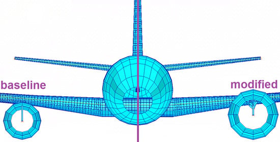
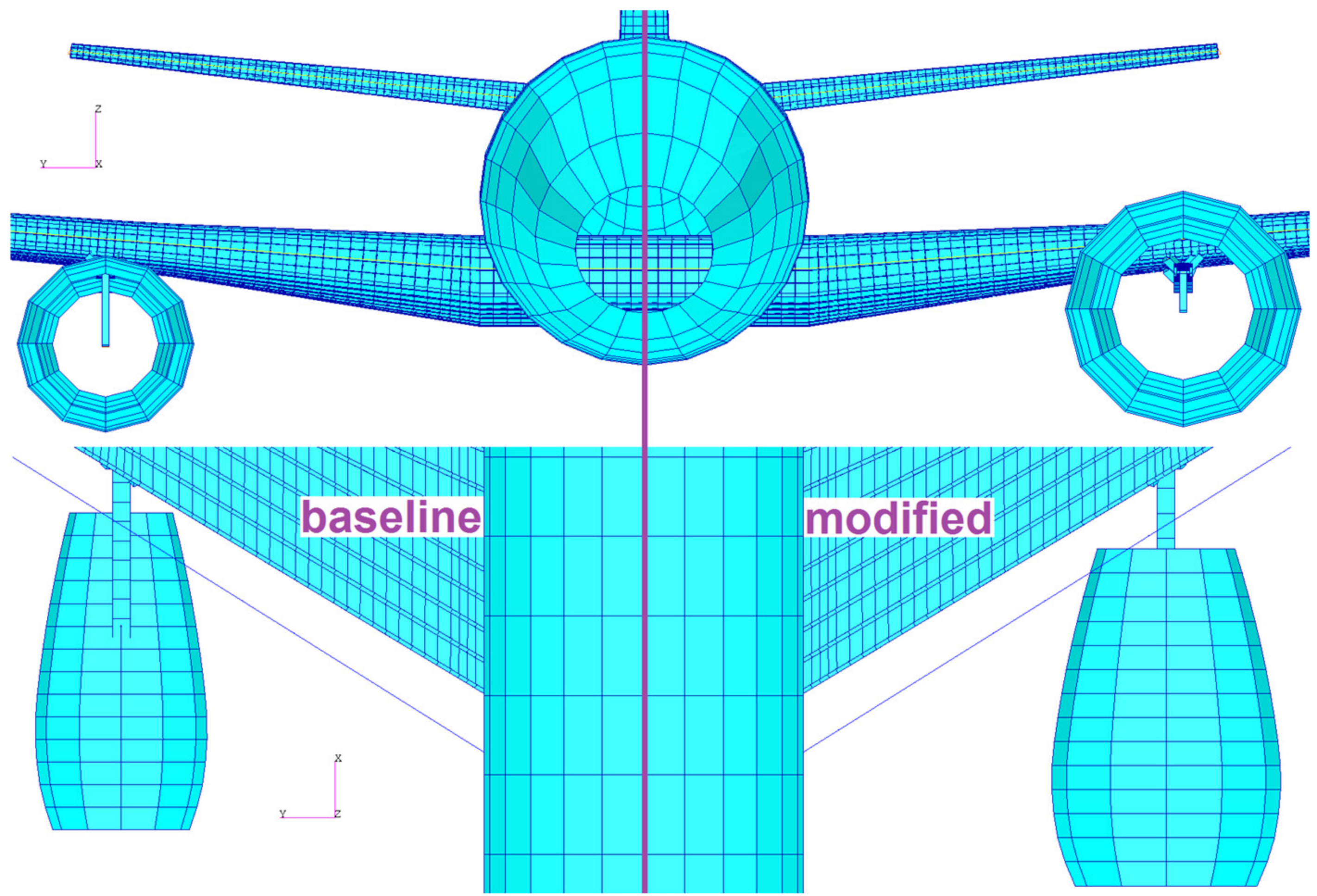
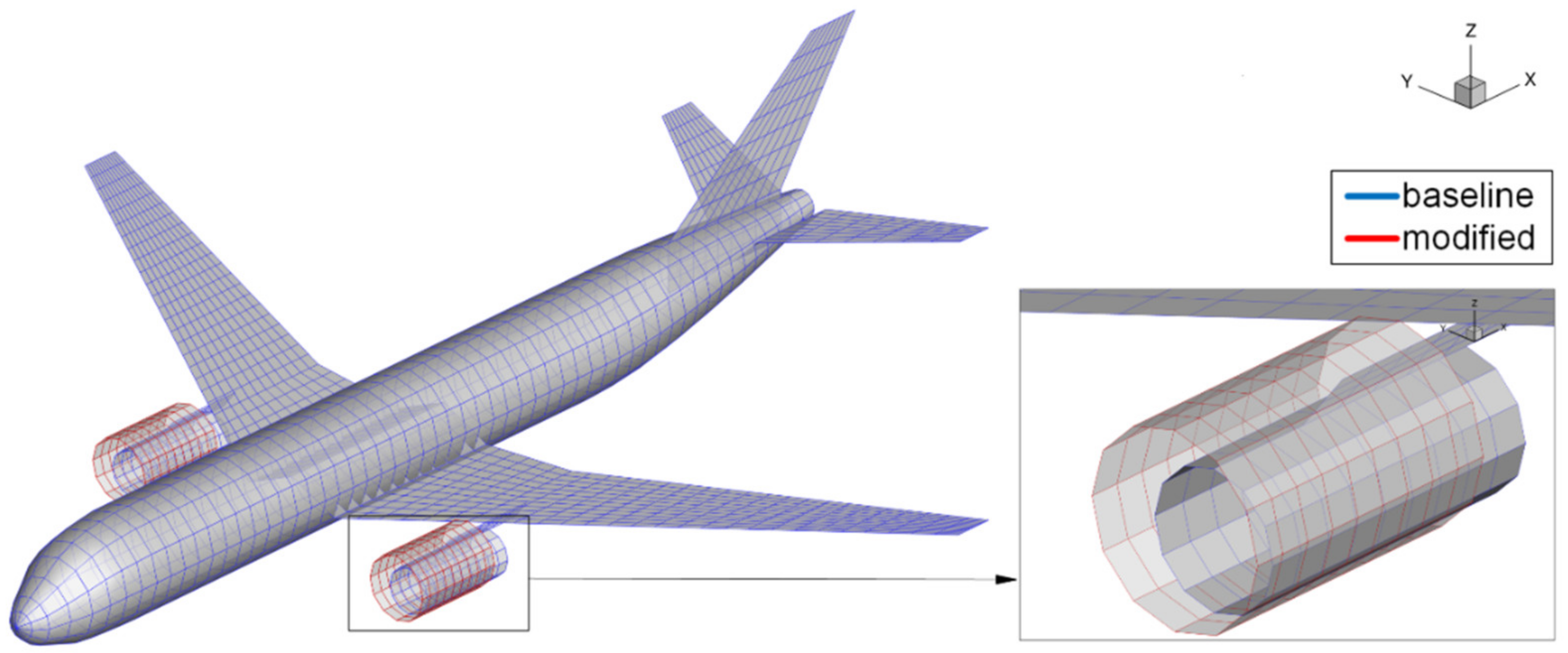
Figure 3 visualizes the difference in the outer shape of the two engine variants. At the top half of Figure 3, it can be seen that the ground clearance between the two variations stays the same. The topology of the load-carrying structures and the element partition is unchanged between the baseline and the modified configuration.
Table 2 lists the engine parameters for the baseline and the modified configuration. The outer diameter is increased by one meter and the mass per engine by 850 kg. The position of the engine’s center of gravity (CG) is shifted one meter to the front and a half meter upwards.
2.2. Parametric Modeling
The simulation models for this paper are generated using the design process cpacs-MONA [22]. At the beginning of this paragraph, the general MONA concept is summarized followed by a fairly detailed description of the automatized cpacs-MONA process. An explicit view of the parametric modeling for the engine-wing integration is presented at the end of this paragraph.
2.2.1. The Basic MONA Process
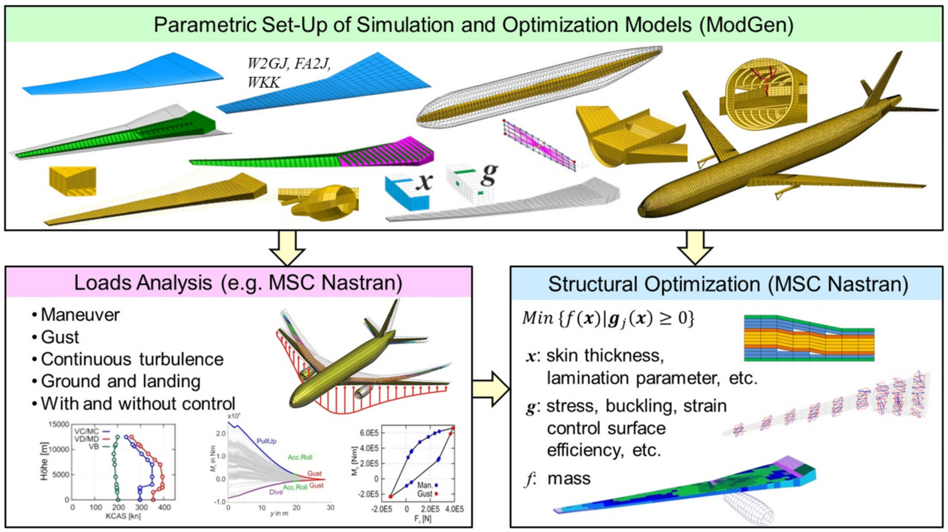
An aeroelastic structural design process can be defined by three main steps: First, there is the model set-up. The second step is the analysis of loads of the flexible structure to estimate the loads a typical aircraft has to withstand. The third step is the structural design, using structural optimization methods. Within the structural optimization step, besides loads of the flexible structure, aeroelastic constraints like sufficient control surfaces efficiency or the avoidance of flutter within the aeroelastic stability envelope can be considered. In order to ensure consistency of all needed simulation and optimization models, a parametric model generator has been developed at the DLR Institute of Aeroelasticity (DLR-AE) over the last 20 years: ModGen [23]. Starting with ModGen, the basic aeroelastic structural design process at DLR-AE, named MONA, is established. Figure 4 highlights the three main steps together with the principal options available within the individual steps. The name MONA is composed of the two main computer programs involved. Besides the already introduced model generator ModGen, the second computer program is the commercial FE-analysis software MSC Nastran [24] used for the aforementioned analyses. The basic MONA process in far more detail is described in Reference [25].
2.2.2. The Automatized cpacs-MONA Process
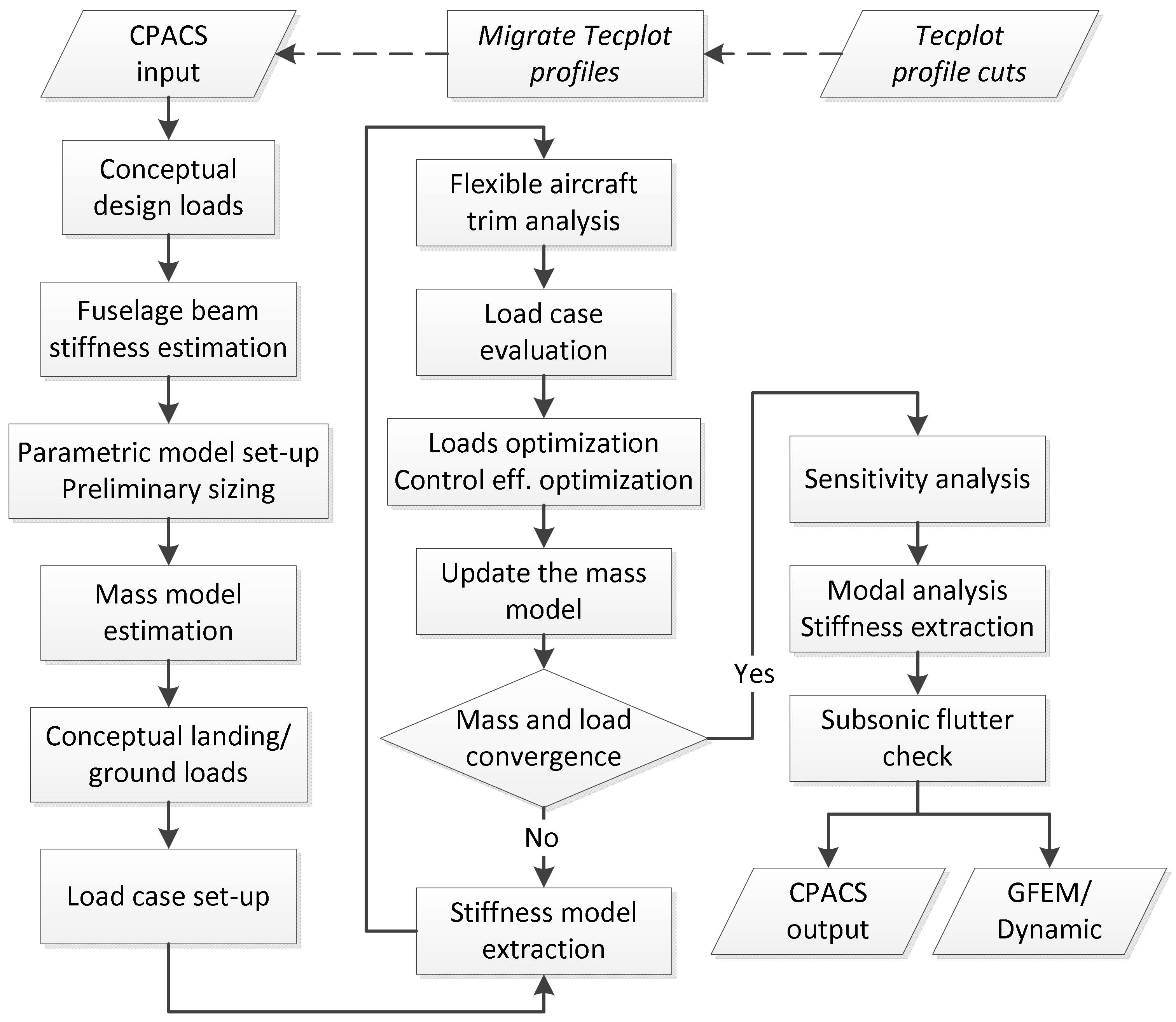
The automatized tool-like process cpacs-MONA has been derived from the basic MONA process to perform aeroelastic structural design for different aircraft configurations. cpacs-MONA is integrated in DLR wide established design processes using a Common Parametric Aircraft Configuration Schema (CPACS) dataset for data exchange. cpacs-MONA can be used as a stand-alone tool (like for this paper) or as part of various aircraft design processes like high-fidelity MDO chains [26,27,28]. cpacs-MONA is built modular and is written in Python code. It extracts the information about the aircraft from a CPACS dataset. CPACS stands for Common Parametric Aircraft Configuration Schema and is written in XML format [29]. CPACS describes a wide range of the aircraft characteristics like the outer geometry (profiles and segments), the global aircraft parameters, the topology of the inner structure, the engine outer shape, and much else. Besides, the aircraft information also processes information like aerodynamic data, aircraft loads, or a more or less detailed mass distribution for each component that can be stored in the CPACS dataset. Moreover, tool parameters are stored in the dataset. cpacs-MONA automatically reads out the information about the wing planform, the wing topology like ribs, spars, and stringer positions, and initial component thicknesses together with the engine, pylon, and landing gear positions and dimensions. It also uses information about aircraft masses like design, primary and secondary masses plus the dimensions of the control surfaces, and the borders of the fuel tanks. With this information, cpacs-MONA creates suitable input-files for the involved tools. For ModGen, each component (wing, horizontal and vertical tail, fuselage) is built separately and executed in parallel. Furthermore, the MSC Nastran simulations like the static aeroelastic trim analysis [30] (solution 144) and the structural optimization analysis [31] (solution 200) can be executed in parallel. Besides the already mentioned tools like ModGen and MSC Nastran, cpacs-MONA combines many tools written in different programming languages forming an automated process flow as shown in Figure 5.
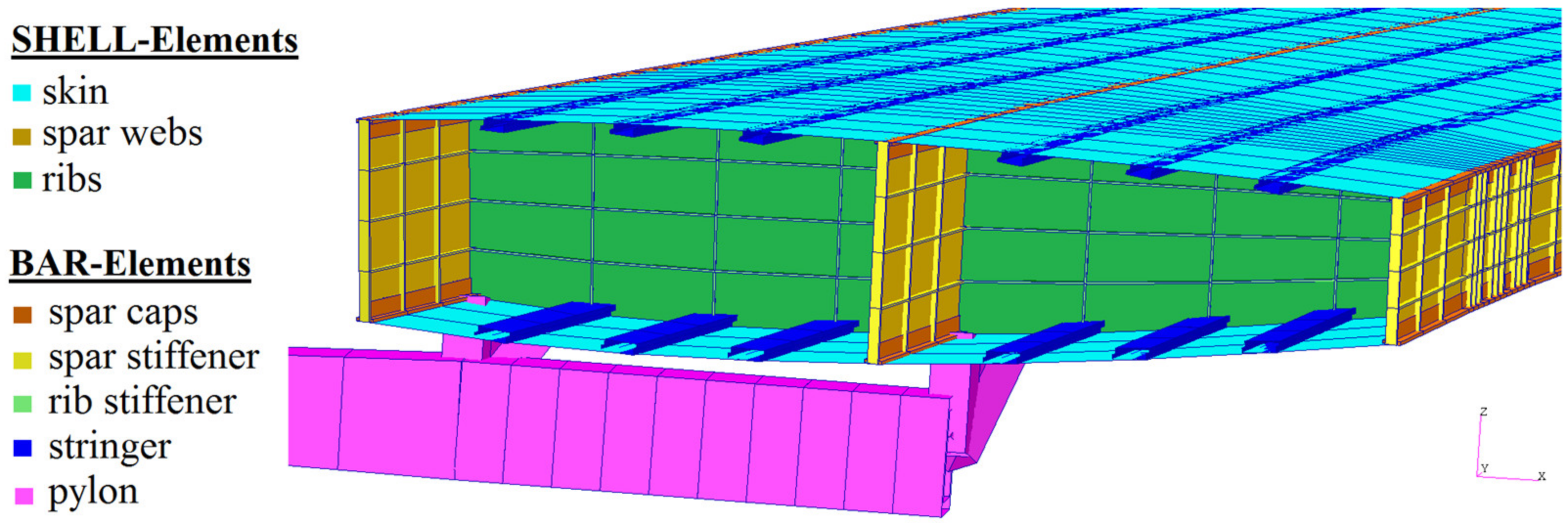
The process starts with an estimation of preliminary loads based on conceptual design methods [32] followed by an estimation of a generic beam model representing the fuselage stiffness. The conceptual loads are used for a preliminary cross-section sizing (PCS) within ModGen [33]. Due to the PCS, a more realistic wing representative with respect to the shell thickness distribution and bar properties is provided. As shown in Figure 6, the wing ribs, spars, and skins are modeled with shell elements. The other wing component structures like the spar caps, the reinforcement structure, or the stringers are modeled with bar or beam elements. The pylon is modeled with beam elements and its structural properties are also defined parametrically as presented in more detail in Section 2.2.3.
For a conclusively substantiated aeroelastic analysis, reasonable mass models have to be set-up. Therefore, a mass model tool reads out the mass-breakdown for each component and creates a model with distributed mass and inertia entities in line with the given geometrical space of the individual component. The fuel tank volume is calculated according to the geometrical borders (ribs, spars) as defined in CPACS. The masses of the engine and landing gear are extracted from the CPACS dataset and converted into CONM2 elements. The resulting operating mass empty (OME) together with defined combinations of fuel and payload/passenger masses form the design masses of the aircraft. The generated mass cases have an internal ID. This ID together with the percentage indication of the payload and fuel compositions used within this work are listed in Table 3.
The mass model set-up is followed by a conceptual ground and landing loads estimation. Then, the trim conditions (load factor, roll rate, pitching velocity, etc.) for the load cases are set-up according to CS-25.335 [34]. For this paper, 730 load cases containing symmetrical pull-up and push-down maneuvers, yawing and rolling maneuvers paired with quasi-stationary gust encounters according to the Pratt formulation are generated. To reduce the complexity of the GFEM/Dynamic for the extensive loads analysis, the stiffness of the structural model is condensed to the loads reference axis (LRA) points. This condensed model is set-up by ModGen using RBE3 interpolation elements with a so-called UM option [35]. This model has the same dynamic characteristic (mass and stiffness) as the full GFEM/Dynamic but much less degrees of freedom. The full model of the DLR-D250 consists of about 35.000 FE-nodes and roughly 42.000 finite elements. The condensed GFEM/Dynamic consists solely of 478 FE-nodes forming the stiffness matrix and the mass model with concentrated mass entities (CONM2-cards) and 352 finite elements. RBE2-elements and corresponding nodes are used for the aeroelastic coupling of the structural and the aerodynamic model. Spline elements transfer the forces and motions between the two models. The condensation reduces the computational effort for the extensive aeroelastic analysis of the flexible aircraft.
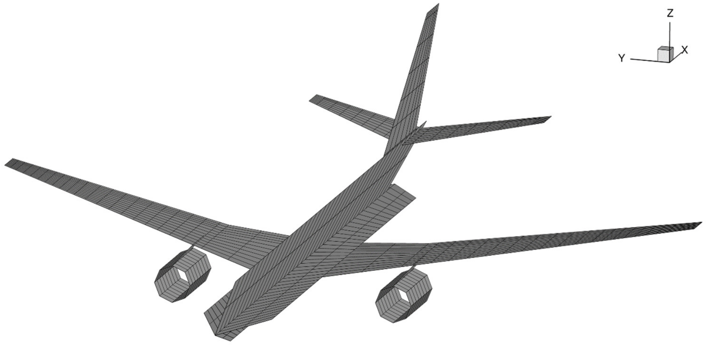
The automatically generated aerodynamic model is shown in Figure 7. This model consists of macro panel elements for the vortex and doublet lattice method (VLM [36] and DLM [37]). Within the elastic trim analysis, the macro panels of the wing-like structures are geometrically corrected to account for the camber and twist effects of the wing. Aerodynamic corrections to account for compressibility effects have not been considered within this publication. The control surfaces like elevator, rudder, and aileron are also defined within the aerodynamic model according to their definition within the CPACS dataset. The structural model does not contain control surfaces.
The load cases with the maximum and minimum cutting moments for torque, shear, and bending are selected for each wing-like component. The forces and moments of these load cases are extracted and used for the structural optimization of the wing-like components. The objective function for the structural optimization is to minimize the wing-box mass under consideration of aeroelastic constraints like control surface efficiency (for the main wing only) or allowable stress values per shell element. The stresses are based on yielding, ultimate strength, and local buckling. As a design variable, the thickness of the shell elements from the load-carrying wing structure can be adjusted to fulfill the objective function. The design variables are combined to design regions to reduce the size of the optimization task. The design regions of the wing-box are on the one hand the partial skin surfaces, surrounded by spars and ribs, and the partial rib and spar surfaces due to their intersections among each other. Since the wing-box of the DLR-D250 main wing consists of 39 ribs and three spars, the optimization model consequently exists of 78 design variables for the ribs, 76 for each skin cover, and altogether 88 for the spars. In total, 318 design variables are optimized to minimize the wing-box mass of the main wing. The dimensions of the reinforcement bar elements (sized within the PCS) are not part of the optimization task. The analysis of loads and structural optimization are iteratively coupled. The mass and the stiffness of the simulation models are updated at each iteration step until the mass and loads of the complete aircraft configuration are converged. For more details on each of the single process steps, see Reference [22].
This degree of process automatization shows that cpacs-MONA does not set-up the simulation models for the two investigated configurations by changing the mass and the outer geometry of the engine. To a greater degree, it optimizes the load-carrying wing structure of each aircraft configuration in an iterative loads and structural optimization loop to best bear the loads coming from the different engine-wing integrations. The resulting structural GFEM/Dynamic models of the two different configurations are afterward used for a manual flutter analysis to investigate the influence of the modified engine on the dynamic aeroelastic behavior of the aircraft.
2.2.3. Parameterized Engine-Wing Integration
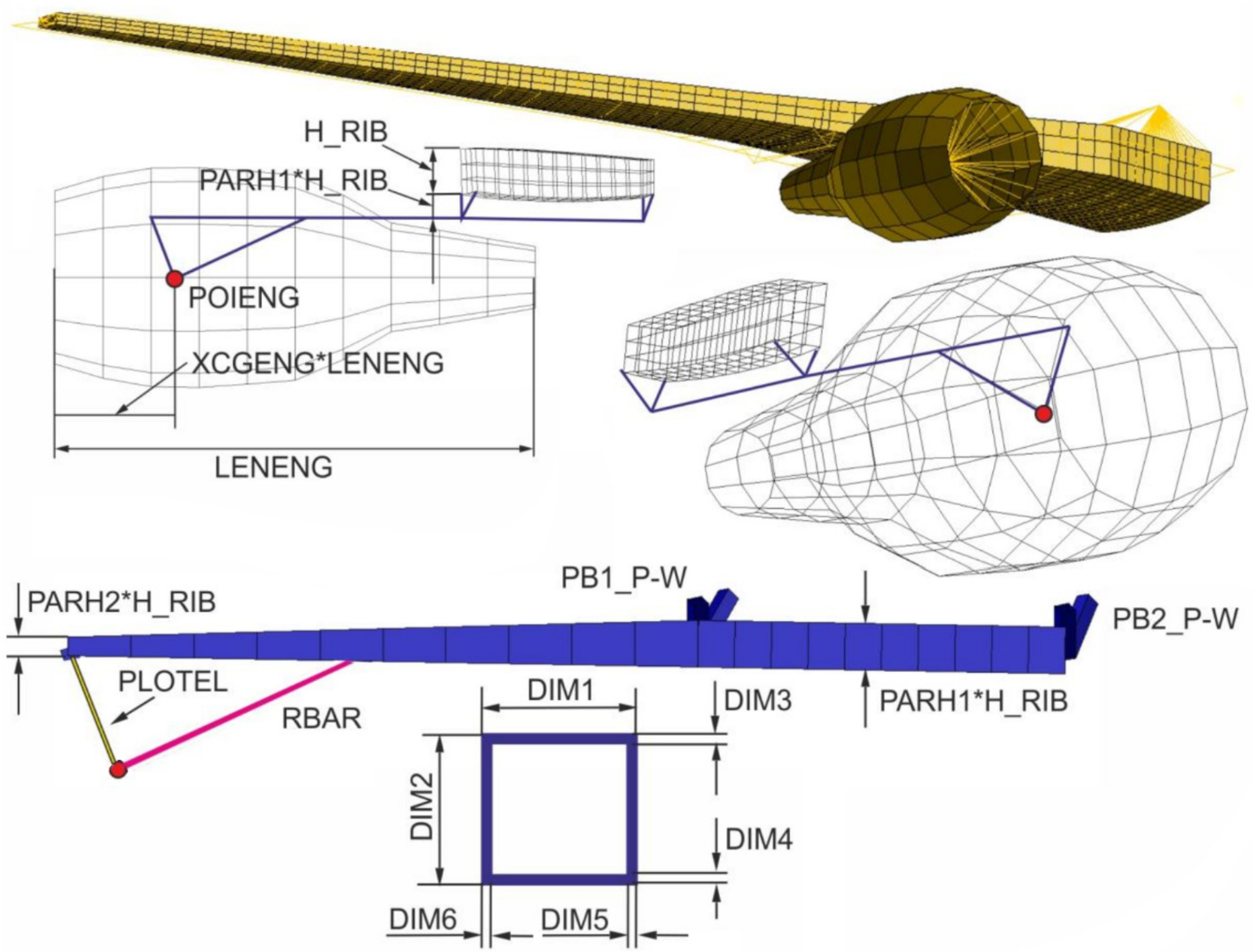
The structural model of the pylon as engine-wing integration unit and the engine’s nacelle are modeled with ModGen. cpacs-MONA reads out the necessary parameters and creates corresponding ModGen input cards. For a wing-mounted pylon-engine model, the ModGen input card is called GEPYLO2. ModGen is also capable of building a parameterized fuselage-mounted engine-pylon model or a turboprop engine frame. The main parameters of the GEPYLO2 card together with a visualization of the structural model of the pylon are shown in Figure 8.
The maximum outer diameter of the engine nacelle and its location are extracted from the CPACS dataset and written into the ModGen input card. For the location, ModGen needs the center of gravity (CG) of the engine (POIENG) and the percentage position of the CG (XCGENG) according to the engine length (LENENG). With these three parameters, the position of the engine is adjusted in the global coordinate system. ModGen directly takes the maximum diameter (MAXDIA) and the length (LENENG) as input parameters. The XCGENG parameter has to be calculated within cpacs-MONA with the known CG position extracted from the CPACS mass-breakdown branch, the nacelle entrance point, and its length.
After the engine is positioned, the structural model of the pylon is set-up. The parameters for the pylon dimensions are not stored within the CPACS dataset. They have to be defined by the user before cpacs-MONA is executed. The pylon structure is built with PBEAML elements according to the Nastran BOX1-type definition. The parameters DIM3 to DIM6 define the wall-thickness of the pylon structure. The width (DIM1) and the height (DIM2) of the pylon are calculated as a function of the parameters PARH1, PARH2, the height of the attachment-rib (H_RIB), and the actual x-position on the pylon (see Figure 8). The preset values for the aforementioned pylon parameters for the baseline and the modified configuration are listed in Table 4.
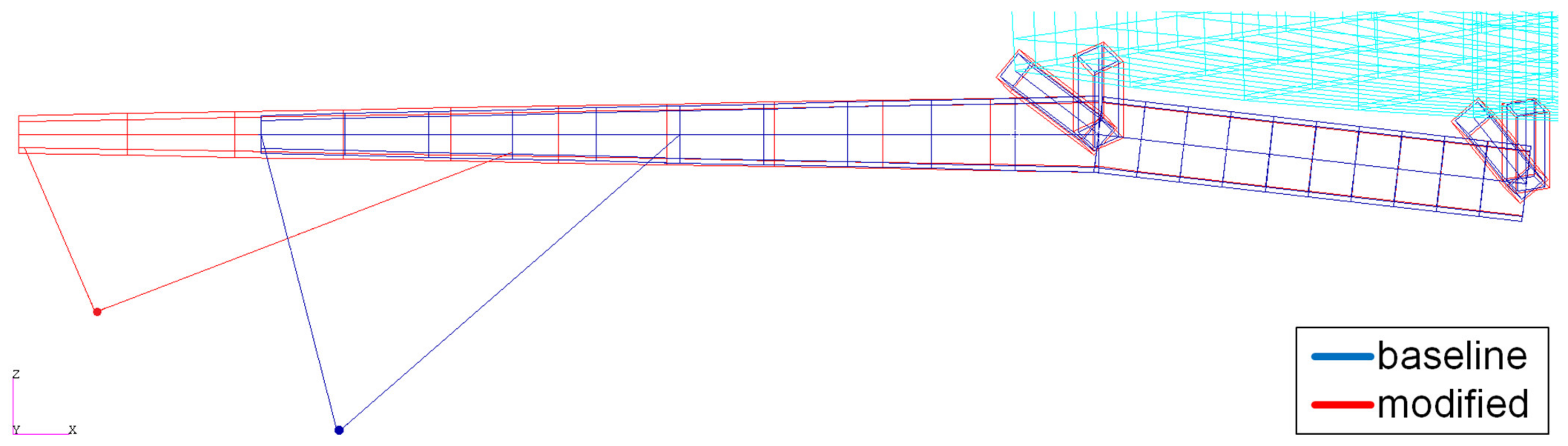
The pylon can be attached to the wing-box at a defined number of rib stations (NBSRBS). Two ribs are used for the DLR-D250. ModGen automatically estimates the ribs for the attachment according to the y-coordinate of the engine. In case the wing box is equipped with a mid-spar, ModGen attaches the pylon to the front- and mid-spar, otherwise to the front- and rear-spar. The attachment structure from the pylon to the wing (PB1_P-W and PB2_P-W) is modeled with Nastran PBARL elements with the BAR-type. Both bar elements for the pylon-wing attachment have the same quadratic cross-section within cpacs-MONA. The attachment structure from the engine mass point to the pylon is modeled with rigid RBAR elements to account for the high stiffness of the core engine. Figure 9 visualizes the resulting pylon structure for both investigated variants.
2.3. Flutter Analysis
For the flutter analysis, which is carried out outside of cpacs-MONA, the commercial software package ZAERO from ZONA Technology is used [38]. ZAERO and its solver ZONA6 uses a panel method to solve the unsteady small disturbance equations in the frequency domain in order to generate aerodynamic influence coefficient matrices (AIC) for a combination of Mach number and reduced frequencies. The AIC matrix is the modal aerodynamic basis for the flutter calculation together with the structure represented by the modal basis of a finite element model. The modal analysis is performed with MSC Nastran (solution 103) to compute the eigen-frequencies and the mode-shapes of the two investigated aircraft configurations. The first 50 eigen-modes including the six rigid body mode-shapes of each GFEM/Dynamic are imported into the ZAERO flutter solver.
To solve the classical flutter equation within ZAERO, the g-method is used for this publication [39]. In comparison to the well-known p-k-flutter solvers, this method introduces a first-order aerodynamic damping term in the flutter equation to get a more realistic approximation for high damping amplitudes. In the case of zero damping (g = 0) with harmonic oscillations, the solution is identical with the widespread k-method and p-k-method. The solution technique of the g-method is especially important when so-called hump modes occur, where for instance flutter appears in a limited low-speed velocity range with moderate excitation, while the damping is recovering again for higher speeds. This behavior can be observed for vibration modes where engines or control surfaces contribute to such aeroelastic characteristics [39]. The non-matched point flutter analysis with fixed Mach number and fixed density is used for all flutter calculations within this publication. The Mach number is set to Ma = 0.8 and the density according to the international standard atmosphere (ISA) to ρ = 0.6597 kg/m3 for the flight level of H = 6000 m. This flight-point is chosen because of the high aerodynamic pressure and the therefrom resulting high eventuality of flutter occurrence.
Figure 10 shows the aerodynamic panel model of the DLR-D250 baseline and modified configuration used for the ZAERO flutter analysis. The modeling guidelines regarding the aerodynamic panels have been considered as described in the ZAERO theoretical manual [40]. The wing panels are modeled with CAERO7-elements and the fuselage with BODY7-elements. The CAERO7 element defines a thin flat plate with unsteady vortex singularities located on the mean plane of the wing-like component. The BODY7 element represents a body macro-element that includes a large number of body boxes. A sheet of constant unsteady source singularity is located on each box to simulate the aerodynamic disturbance due to the volume effect of the body [40]. To cancel the strong vortex line at the inboard edge of the wing panels located at the wing-fuselage junction, VCT-panels (vortex carry through) are introduced into the model. For the baseline configuration, both the engine and the pylon are modeled with CAERO7 panels. The engine panels are arranged in a circle, as highlighted in Figure 10. For the modified configuration with the bigger engine, the panels for the pylon are neglected for modeling reasons. Control surfaces have neither been modeled within the structural model nor the aerodynamic model. All other aerodynamic lifting surfaces and their discretization are unchanged between the two configurations.
3. Results
The results from the automated loads and aeroelastic design process cpacs-MONA are highlighted in the first section of this chapter. At first, the two configurations are investigated and compared in terms of flight loads. Thereafter, the thickness distribution of the main wing as a result of the structural optimization is pointed out. In the flutter analysis paragraph, first of all, the influence of the different mass configurations on the flutter characteristics is investigated for the baseline configuration. Afterward, the leverage of the bigger and heavier engine on the flutter characteristics for the most flutter-critical mass configuration is exhibited.
3.1. Resulting Flight Load Distribution
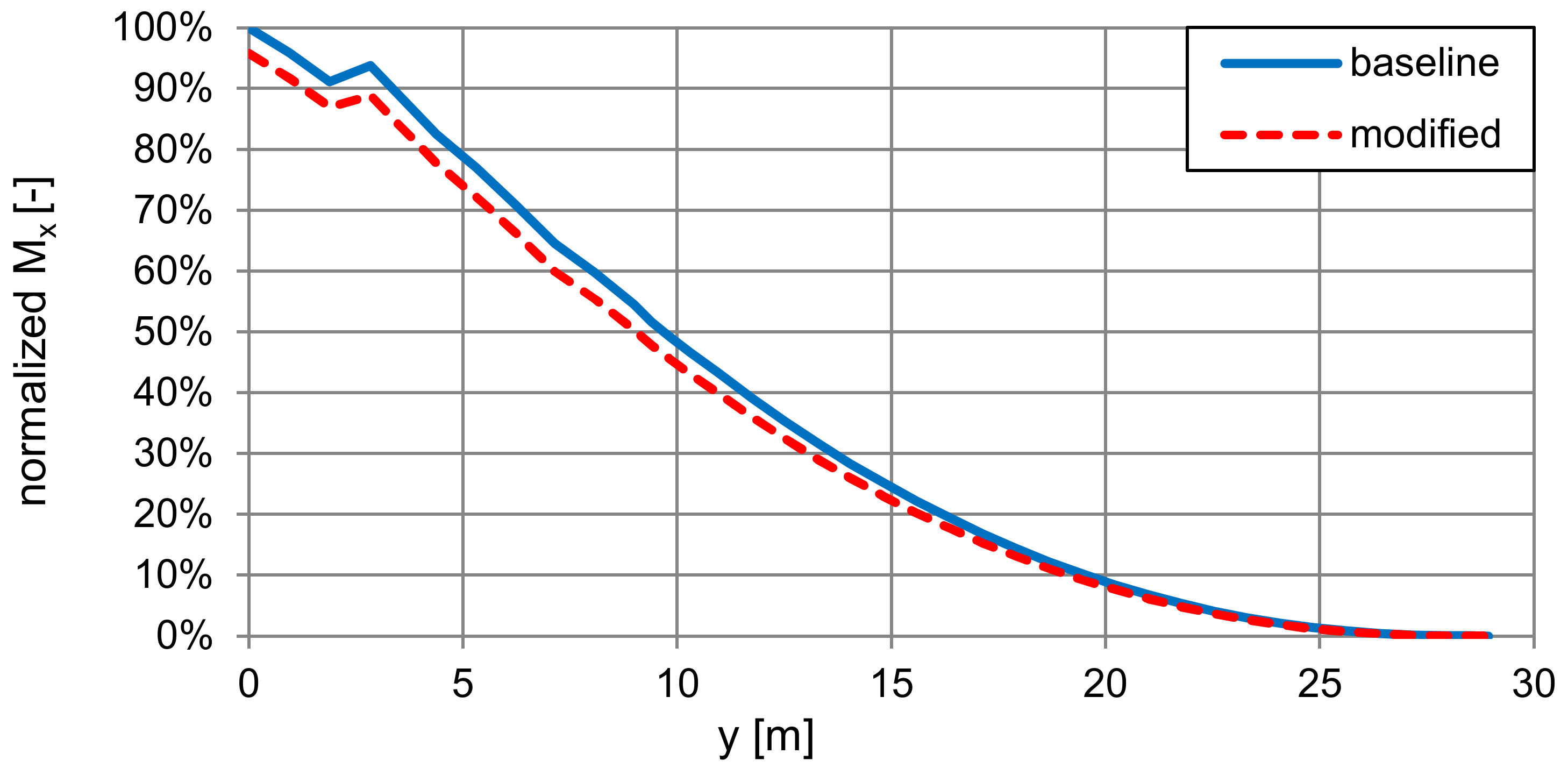
Since one of the main tasks of the cpacs-MONA process is the analysis of loads of a complete and flexible aircraft configuration, the two variants are investigated on the topic aeroelastic loads within the following section. cpacs-MONA comprises among other load conditions pull-up maneuvers with load factors of 2.5 g. Due to the fact that most of the aircraft mass is located in the fuselage, the aerodynamic loads on such an intense load case are dominating at the main wing and mainly determine the dimensioning loads. The inertia loads from the heavier engine lead to a relief of the total flight loads acting on the main wing due to the fact that the inertia loads are counteracting the aerodynamic loads. Figure 11 shows the internal bending moment distribution and Figure 12 the internal torsion moment over the span for the main wing for the two investigated configurations. The internal moments are normalized using the maximum value of the baseline variant.
For both variants, the same load case leads to the maximum bending and minimum torsional loads: The 2.5 g pull-up maneuver with dive speed (VD) at flight level 430 with the maximum take-off mass configuration with full payload and filled-up fuel (MTOAa). For the torsion, the maximum cutting loads on the root section occur at a push-down maneuver for the same mass configuration and flight level as for the aforementioned load case at cruise speed (VC).
For the bending moment, the heavier engine leads to a reduction of nearly five percent at the root section. A reduction applies up to 2/3 of the wingspan. For the torsion (Figure 12), a reduction of the maximum wing root cutting moment of about 20 percent can be seen for the modified configuration with the heavier and farther forward located engine with respect to the baseline configuration. The reduction applies to the center wing-box (CWB) part. From the CWB to the engine attachment point (y = 9.3 m), the torsional cutting moment for the modified configuration is higher as for the baseline. For this area, also the MTOAa mass case but a pull-up maneuver at the design maneuvering speed (VA) at sea-level is dominant for both variants.
3.2. Resulting Wing Thickness Distribution
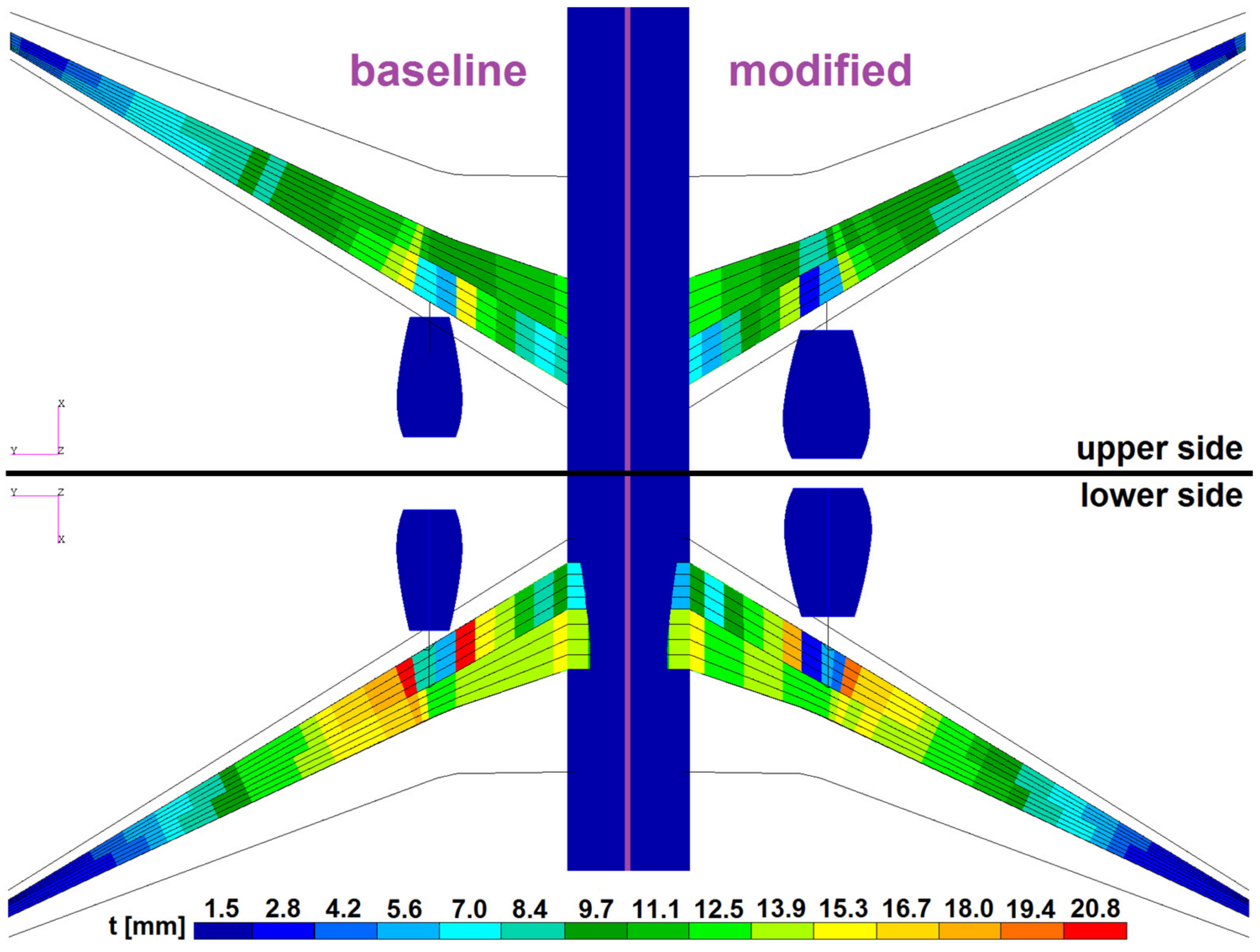
For the modified configuration, the heavier engine initially leads to an increase in the OME. The maximum take-off mass (MTOM) for both configurations is kept unchanged. That leads to the mass case generation to a reduction of the possible payload/fuel capacity for the modified configuration. Since the reduction on the loads side is accompanied by a reduction of the structural wing mass for the modified configuration with the heavier engines, the payload/fuel capacity for both configurations re-approached within each iteration step. The converged primary mass of the wain wing is 22.616 kg for the baseline and 20.845 kg for the modified configuration. The difference in the primary wing masses (1.771 kg) is about the same amount as the difference in the total engine mass (1.700 kg). At the end, the OME of both aircraft configurations differs 87 kg in total. It follows from the foregoing that the mass cases in terms of mass and CG-position for the two investigated configurations are comparable. Another important outcome of the structural optimization within cpacs-MONA, beside the minimized mass of the converged load-carrying wing structure, is the resulting thickness distribution across the wingspan due to the load changes. Figure 13 shows the thickness distribution for the upper and lower skin of the main wing for both configurations. On the upper skin, the changes from the baseline to the modified configuration are marginal. The same applies to the tip-section of the lower side. On the lower side, the changes are more visible for the mid-section (engine attachment) of the wing, where Section 3.1 mentioned that relief of the total flight loads leads to a decrease of skin thickness for the modified configuration.
One important fact to highlight for the structural optimization results: cpacs-MONA does only account for the conceptual ground without the consideration of the engine masses. In case landing loads are also considered for the structural optimization of the wing, it is expected that the shown trend of thickness decrease at the engine attachment area would be disproven for the heavier, higher, and farther forward located engine.
3.3. Results on the Flutter Analysis
The first flutter investigation should reveal the most critical flutter case (lowest flutter speed) for the baseline configuration affected by the different payload/fuel configurations according to Table 3. The results for the damping behavior of the most critical flutter case for the different mass cases are shown in Figure 14. The lowest flutter speed occurs at the OME (MOOee—red line) case without any payload or fuel. Nearly the same result accrues by the maximum zero fuel case (MZOAe—green line). The MTOM case with full fuel tanks and filled-up payload (MTOfF) has no aerodynamic influence concerning flutter within the investigated airspeed region and, therefore, is not illustrated in Figure 14. The other two investigated mass cases have a higher flutter speed and, therefore, are not that critical as the mass configurations with empty fuel tanks. The important results of the flutter analysis for the different mass cases of the baseline configuration are listed in Table 5.
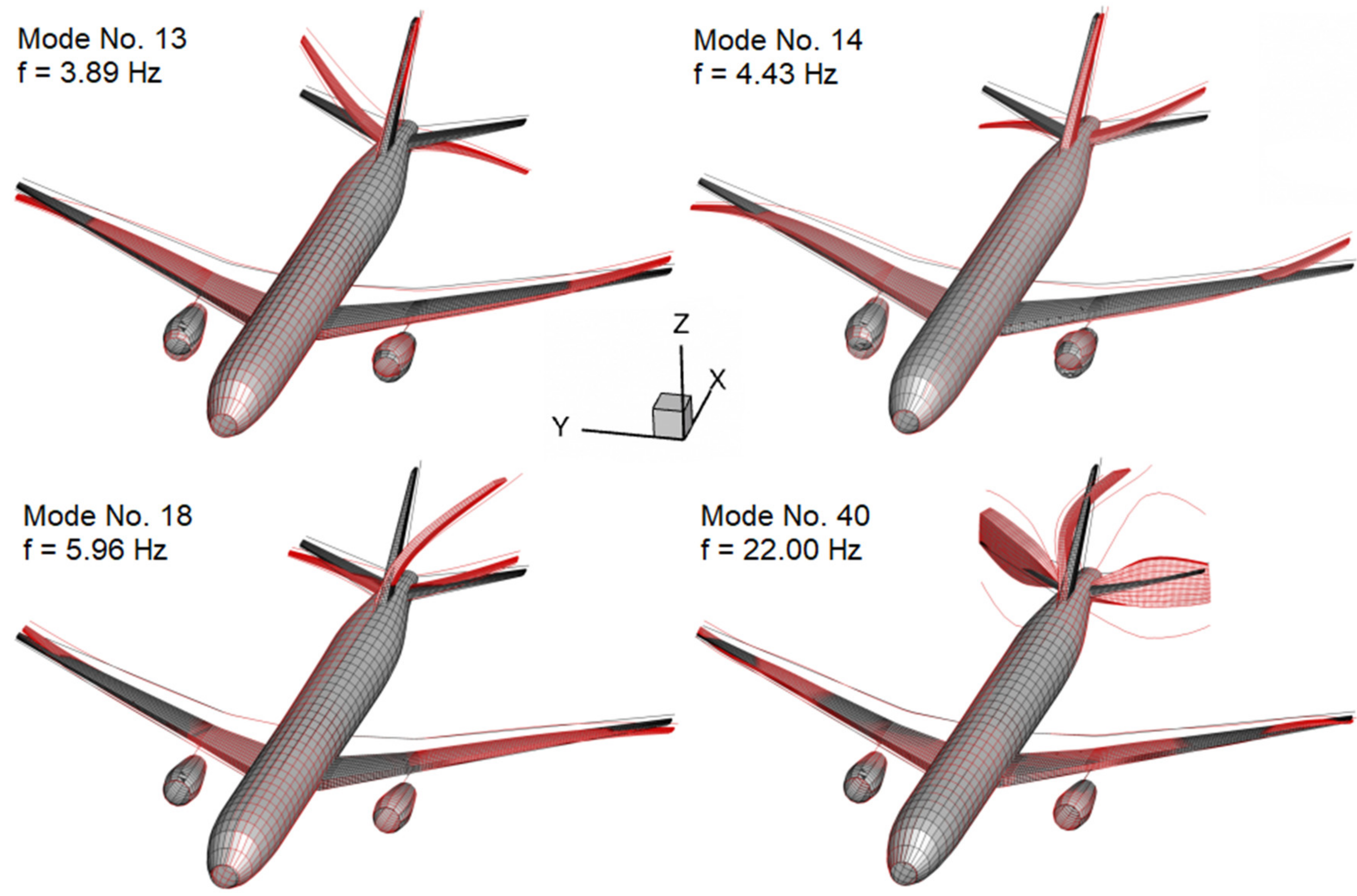
The flutter case itself is a classical bending coupled with a torsional twist of the horizontal tail-plane (HTP). Involved in this flutter case are the antisymmetric first bending modes of the HTP (number 13 and 14), the first bending mode of the vertical tail-plane (number 18) as well as the first antisymmetric torsional mode of the HTP together with the second vertical tail-plane bending mode (number 40), as depicted in Figure 15. These mode shapes are involved in the flutter case with 100% participation.
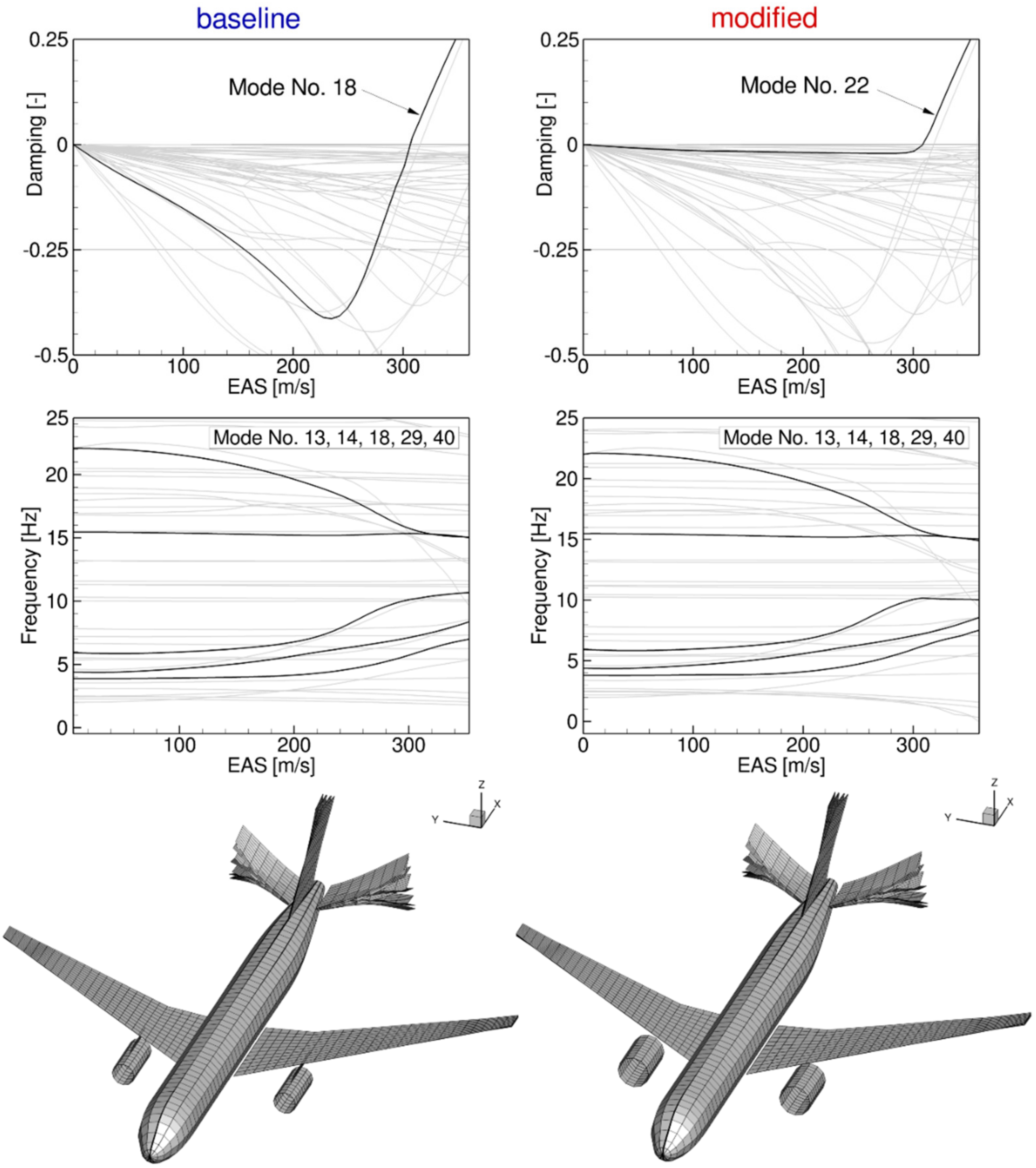
The second flutter investigation is intended to show the influence of the engine and pylon changes on the critical flutter speed and the flutter characteristic. For the most critical payload/fuel combination (MOOee) with the new structural dynamic behavior of the optimized modified configuration and the new aerodynamic model of the bigger engine, an additional flutter analysis is performed. The results for damping, frequencies, and the flutter mode shapes for both the baseline and the modified configuration are depicted in Figure 16. It can be seen that the flutter modes themselves change. The critical aeroelastic flutter mode switches from mode no. 18 to mode no. 22 for the modified configuration. The reason for that behavior lies in the adjacency of the critical modes no. 18 and no. 22. By changing the configuration, mode no. 18 gets more damped than mode no. 22. Nevertheless, both flutter modes show the same flutter mechanism, the bending-torsion coupling of the horizontal tail-plane. The changes of the engine size, the engine mass, and its location together with the pylon stiffness have a positive influence on the flutter behavior. The lowest flutter speed increases slightly from 306.5 m/s to 308.6 m/s equivalent airspeed (EAS), while the flutter characteristic of the DLR-D250 configuration stayed unchanged.
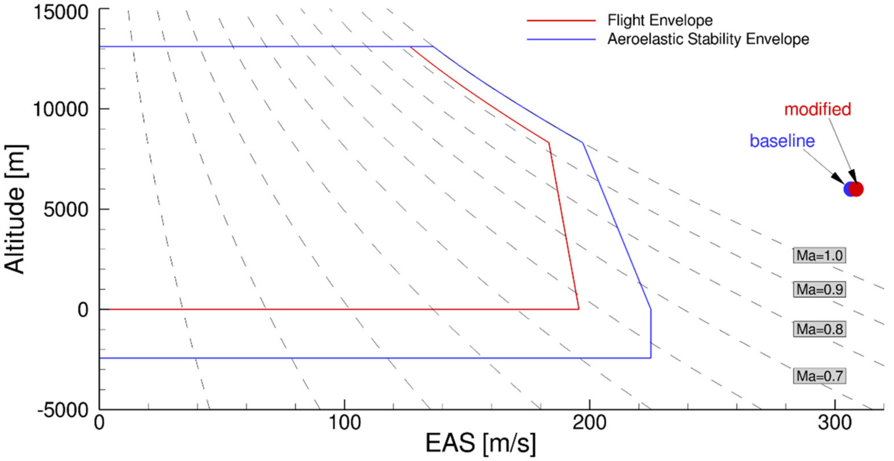
Finally, the most critical flutter cases for the two investigated configurations, which are identified for the payload-fuel configuration MOOee, are plotted in the aeroelastic stability envelope displayed in Figure 17. The flight and flutter envelope are generated accordingly to the certification specifications for large airplanes (CS-25). For both configurations, the calculated flutter points are clearly outside of the aeroelastic stability envelope.
4. Conclusions
The main objective of this publication is to highlight the parametric modeling capability of the automatized aeroelastic design process cpacs-MONA. Especially, the parametrization of the engine-wing integration and the capability to set up a finite element model for the complete aircraft (GFEM) for aeroelastic analysis is emphasized. A generic long-range transport aircraft configuration, the DLR-D250, is taken as reference. A modified configuration with a bigger and heavier engine mounted farther forward and higher together with an appropriate stiffer pylon is generated with cpacs-MONA by easily changing a few parameters within the CPACS dataset.
Both configurations have first been examined according to the influence of the modified engine on the flight loads and the consequential structural optimization results for the main wing. It is shown that the higher engine mass leads to a reduction of the flight loads for the main wing and, therefore, to a reduction of the optimized structural mass of the load-carrying structure. The consideration of landing loads might mitigate the effect.
The generated GFEM/Dynamic models from cpacs-MONA are used for further investigations concerning flutter using ZAERO. This investigation is done outside of cpacs-MONA and shows the smooth usability of the generated simulation models for other processes. First, the OEM case is detected as a mass configuration with the lowest flutter speed of the baseline variant. As a flutter case with the lowest speed, a classical bending coupled with a torsional twist of the horizontal tail-plane is identified. Afterward, the influence of the modified engine on the most critical flutter case is revealed. The influence of the modified engine is almost negligible with respect to the most critical flutter phenomenon of the DLR-D250 configuration, which is the HTP flutter case for both variants. However, it is shown that the higher mass together with the farther forward position of the engine slightly increases the flutter speed of the aircraft configuration. This effect shows the necessity of equipping simulation models with a plausible engine and pylon model. A possible explanation for the flutter sensitivity of the DLR-D250´s HTP might be the insufficient sizing of the HTP´s wing-box structure since no dynamic gust loads have been considered within cpacs-MONA for this study.
A plausible next step will be, to choose another reference aircraft configuration, where the classical bending-torsional coupling of the main wing is the critical flutter case, or to adapt the wing of the DLR-D250 configuration to be more prone to flutter. For such a configuration, a detailed investigation of the engine-wing integration can easily be performed with the here developed process to reveal the influence of the engine-wing integration parameters in a critical wing-flutter case.
Moreover, the structural optimization of the pylon itself is expected to be a promising aspect when introducing a bigger and heavier engine mounted farther forward and higher at the wing since the pylon design and stiffness has a direct impact on the structural dynamics of the engine-wing interaction.
Author Contributions
Conceptualization, methodology, investigation, visualization, validation, data curation, writing—original draft preparation, M.S. and J.N.; software, formal analysis, resources, writing—review and editing, M.S., J.N., and T.K. All authors have read and agreed to the published version of the manuscript.
Funding
This research received no external funding.
Acknowledgments
The authors would like to thank Jan Schwochow for the helpful feedback regarding the investigation of the results from the flutter analysis.
Conflicts of Interest
The authors declare no conflict of interest.
Abbreviations
| AE | Institute of Aeroelasticity |
| AIC | Aerodynamic influence coefficient |
| CAD | Computer-aided design |
| CG | Center of gravity |
| CPACS | Common Parametric Aircraft Configuration Schema |
| CS-25 | Certification specifications for large airplanes |
| CWB | Center wing-box |
| DLM | Doublet lattice method |
| DLR | German Aerospace Center / Deutsches Zentrum für Luft und Raumfahrt |
| EAS | Equivalent airspeed |
| GFEM | Global finite element model |
| HTP | Horizontal tail-plane |
| LE | Leading edge |
| LRA | Loads reference axis |
| MDO | Multidisciplinary Design Optimisation |
| MTOM | Maximum take-off mass |
| MZFM | Maximum zero-fuel mass |
| neo | New engine option |
| OME | Operating mass empty |
| PCS | Preliminary cross-section sizing |
| RBE2 | Rigid Body Element No.2 |
| UAV | Unmanned aerial vehicle |
| VCT | Vortex carry through |
| VLM | Vortex lattice method |
References
- Kellari, D.; Crawley, E.F.; Cameron, B.G. Influence of Technology Trends on Future Aircraft Architecture. J. Aircr. 2017, 54, 2213–2227. [Google Scholar] [CrossRef] [Green Version]
- Cumnuantip, S. Landing Gear Positioning and Structural Mass Optimization for a Large Blended Wing Body Aircraft. Ph.D. Thesis, DLR-Forschungsbericht, Goettingen, Germany, July 2014. [Google Scholar]
- Chai, S.T.; Mason, W.H. Landing Gear Integration in Aircraft Conceptual Design; Virginia Polytechnic Institute and State University: Blacksburg, VA, USA, 1997. [Google Scholar]
- Li, J.; Gao, Z.; Huang, J.; Zhao, K. Aerodynamic design optimization of nacelle/pylon position on an aircraft. Chin. J. Aeronaut. 2013, 26, 850–857. [Google Scholar] [CrossRef] [Green Version]
- Guenot, D.; Gallard, F.; Brezillon, J.; Merillac, Y. Aerodynamic optimization of a parametrized engine pylon on a mission path using adjoint method. In Proceedings of the 7th European Conference on Computational Fluid Dynamics, Glasgow, UK, 11–15 June 2018. [Google Scholar]
- Wang, L.; Wan, Z.; Wu, Q.; Yang, C. Aeroelastic modeling and analysis of the wing/engine system of a large aircraft. Procedia Eng. 2012, 31, 879–885. [Google Scholar] [CrossRef] [Green Version]
- Latif, R.; Khan, M.; Javed, A.; Shah, S.; Rizvi, S. A semi-analytical approach for flutter analysis of a high-aspect-ratio wing. Aeronaut. J. 2020, 1–20. [Google Scholar] [CrossRef]
- Amoozgar, M.; Irani, S.; Vio, G. Aeroelastic instability of a composite wing with a powered-engine. J. Fluids Struct. 2013, 36, 70–82. [Google Scholar] [CrossRef]
- Fazelzadeh, S.A.; Mazidi, A.; Kalantari, H. Bending-torsional flutter of wings with an attached mass subjected to a follower force. J. Sound Vib. 2009, 323, 148–162. [Google Scholar] [CrossRef]
- Mardanpour, P.; Hodges, D.H.; Neuhart, R.; Graybeal, N. Engine Placement Effect on Nonlinear Trim and Stability of Flying Wing Aircraft. J. Aircr. 2013, 50, 1716–1725. [Google Scholar] [CrossRef]
- Jonsson, E.; Mader, C.A.; Martins, J.R.R.A.; Kennedy, G.J. Computational modeling of flutter constraint for high-fidelity aerostructural optimization. In Proceedings of the AIAA SciTech Forum, San Diego, CA, USA, 7–11 January 2019. [Google Scholar]
- Cavagna, L.; Ricci, S.; Travaglini, L. NeoCASS: An integrated tool for structural sizing, aeroelastic analysis and MDO at conceptual design level. Progress Aerosp. Sci. 2011, 47, 621–635. [Google Scholar] [CrossRef]
- Manzano, M.D.L.M.S. Studying Aeroelastic Behavior of Aircraft with NeoCASS. The Danbus Configuration, Stockholm: KTH Royal Institute of Technology; Department Aeronautical and Vehicle Engineering: Stockholm, Sweden, 2011. [Google Scholar]
- Waitz, S.; Hennings, H. The Aeroelastic Impact of Engine Thrust and Gyroscopics on Aircraft Flutter Instabilities; IFASD: Saint Petersburg, Russia, 2015. [Google Scholar]
- Pfeiffer, T.; Moerland, E.; Böhnke, D.; Nagel, B.; Gollnick, V. Aircraft Configuration Analysis Using a Low-Fidelity, Physics Based Aerospace Framework Under Uncertainty Considerations; International Council of the Aeronautical Sciences: Saint Petersburg, Russia, 2014. [Google Scholar]
- Moerland, E.; Siggel, M.; Kleinert, J. DLR-SC TIGL Testdata, CPACS Dataset D250. Available online: https://github.com/DLR-SC/tigl/blob/master/tests/unittests/TestData/CPACS_30_D250_10.xml (accessed on 15 December 2020).
- European Aviation Safety Agency. Type Certificate Data Sheets (TCDS) EASA.A.004-A330; European Aviation Safety Agency: Cologne, Germany, 10 September 2020; Available online: https://www.easa.europa.eu/sites/default/files/dfu/A330EASACDSA.004-Issue58-Core.pdf (accessed on 9 November 2020).
- European Aviation Safety Agency. Type Certificate Data Sheets (TCDS) EASA.E.042-Trent 700 Series Engines; European Aviation Safety Agency: Cologne, Germany, 20 December 2019; Available online: https://www.easa.europa.eu/sites/default/files/dfu/EASAE042TCDSissue06_Trent700.pdf (accessed on 9 November 2020).
- European Aviation Safety Agency. Type Certificate Data Sheets (TCDS) EASA.E.036-Trent 1000 Series Engines; EASA: Cologne, Germany, 20 July 2018; Available online: https://www.easa.europa.eu/sites/default/files/dfu/TCDSE036issue10.pdf (accessed on 9 November 2020).
- Rolls-Royce, Future Products-UltraFan. Available online: https://www.rolls-royce.com/products-and-services/civil-aerospace/future-products.aspx#section-overview (accessed on 8 December 2020).
- Clean Sky, The UHBR Engine Flight Testing Programme Gathers Momentum. 2020. Available online: https://www.cleansky.eu/the-uhbr-engine-flight-testing-programme-gathers-momentum (accessed on 9 December 2020).
- Klimmek, T.; Schulze, M.; Abu-Zurayk, M.; Ilic, C.; Merle, A. cpacs-MONA–An Independent and in High-Fidelity Based MDO Tasks Integrated Process for the Structural and Aeroelastic Design of Aircraft Configurations; IFASD: Savannah, GA, USA, 2019. [Google Scholar]
- Klimmek, T. Parametrization of Topology and Geometry for the Multidisciplinary Optimization of Wing Structures. In Proceedings of the European Air and Space Conference, Manchester, UK, 26–29 October 2009. [Google Scholar]
- MSC Software Corporation. MSC Nastran 2017 Quick Reference Guide; MSC Software: Newport Beach, CA, USA, 2016. [Google Scholar]
- Klimmek, T. Statische Aeroelastische Anforderungen Beim Multidiszipliären Strukturentwurf von Verkehrsflugzeugen. Ph.D. Thesis, German Aerospace Center, Goettingen, Germany, 2016. [Google Scholar]
- Merle, A.; Ilic, C.; Abu-Zurayk, M.; Häßy, J.; Becker, R.-G.; Schulze, M.; Klimmek, T. High-Fidelity Adjoint-based Aircraft Shape Optimization with Aeroelastic Trimming and Engine Coupling; EUROGEN: Guimarães, Portugal, September 2019. [Google Scholar]
- Abu-Zurayk, M.; Merle, A.; Caslav, I.; Goertz, S.; Schulze, M.; Klimmek, T. A Comparison of Different Formulations for Aero-Structural Optimization of Trimmed Transport Aircraft; EUROGEN: Guimarães, Portugal, 2019. [Google Scholar]
- Görtz, S.; Ilic, C.; Jepsen, J.; Leitner, M.; Schulze, M.; Schuster, A.; Scherer, J.; Becker, R.-G.; Zur, S.; Petsch, M. Multi-Level MDO of a Long-Range Transport Aircraft Using a Distributed Analysis Framework; AIAA: Denver, CO, USA, 2017. [Google Scholar]
- Nagel, B.; Böhnke, D.; Gollnick, V.; Schmollgruber, P.; Rizzi, A.; la Rocca, G.; Alonso, J.J. Communication in aircraft design: Can we establish a common language? In Proceedings of the ICAS, 28th International Congress of the Aeronautical Sciences, Brisbane, Australia, 23–28 September 2012. [Google Scholar]
- MSC Software. MSC Nastran 2017 Aeroelastic Analysis User’s Guide; MSC Software: Newport Beach, CA, USA, 2016. [Google Scholar]
- MSC Software. MSC Nastran 2017 Design Sensitivity and Optimization User’s Guide; MSC Software: Newport Beach, CA, USA, 2016. [Google Scholar]
- Chiozzotto, G.P. CDloads: Conceptual Design Loads Estimation; DLR-Institute of Aeroelastcity: Goettingen, Germany, 2013. [Google Scholar]
- Van Dalen, F. MDO Load Analysis and Preliminary Sizing; Delft University of Technology: Delft, The Netherlands, December 1996. [Google Scholar]
- Federal Aviation Administration. Federal Aviation Regulations Part 25 C; Airworthiness Standards: Transport Category Airplanes; Federal Aviation Administration (FAA): Washington, DC, USA, 2010. [Google Scholar]
- Guyan, R.J. Reduction of stiffness and mass matrices. AIAA J. 1965, 3, 380. [Google Scholar] [CrossRef]
- Hedman, S.G. Vortex Lattice Method for Calculation of Quasi Steady State Loadings on Thin Elastic Wings; Technical Report 105; FFA—The Aeronautical Institute of Sweden: Stockholm, Sweden, 1966. [Google Scholar]
- Albano, E.; Rodden, W.P. A doublet-lattice method for calculating lift distributions on oscillating surfaces in subsonic flows. AIAA J. 1969, 7, 279–285. [Google Scholar] [CrossRef]
- ZONA Technology, Inc. ZAERO User’s Manual Version 9.2, 3rd ed.; ZONA Technology, Inc.: Scottsdale, AZ, USA, 2017. [Google Scholar]
- Chen, P. Damping Perturbation Method for Flutter Solution: The g-Method. AIAA J. 2000, 38, 1519–1524. [Google Scholar] [CrossRef]
- ZONA Technology, Inc. ZAERO Theroetical Manual Version 9.2, 3rd ed.; ZONA Technology, Inc.: Scottsdale, AZ, USA, 2018. [Google Scholar]
Figure 1.
Global finite element model (GFEM)/Dynamic of the DLR-D250 baseline configuration.

Figure 2.
Structural topology of the wing-box for the main wing of the DLR-D250 GFEM (exploded view).
Figure 2.
Structural topology of the wing-box for the main wing of the DLR-D250 GFEM (exploded view).

Figure 3.
Visualization of the engine’s outer shape—baseline left; modified right.

Figure 4.
The basic MONA process.

Figure 5.
Process flow of cpacs-MONA.

Figure 6.
Wing topology of the generated wing FE-model with the applied elements.

Figure 7.
MSC Nastran aerodynamic mesh of the DLR-D250 used for the elastic trim analysis.

Figure 8.
Visualization of the parameters for the pylon and engine modeling for the wing integration.
Figure 8.
Visualization of the parameters for the pylon and engine modeling for the wing integration.

Figure 9.
Pylon structural model visualization of the baseline and modified configuration.

Figure 10.
Used aerodynamic panel model of the two variants for the flutter analysis within ZAERO.

Figure 11.
Normalized maximum bending moment (Mx) over the span, comparison of the two variants.

Figure 12.
Normalized maximum torsional moment (My) over the span, comparison of the two variants.

Figure 13.
Converged thickness distribution of the upper and lower skin—baseline left; modified right.
Figure 13.
Converged thickness distribution of the upper and lower skin—baseline left; modified right.

Figure 14.
Influence of the payload/fuel combinations on the critical flutter characteristic for the baseline.
Figure 14.
Influence of the payload/fuel combinations on the critical flutter characteristic for the baseline.

Figure 15.
Mode shapes and vacuum frequencies of the GFEM/Dynamic for the baseline configuration.

Figure 16.
Damping, frequency, and flutter mode of the most critical mass case (MOOee) for the baseline (left) and the modified configuration (right).
Figure 16.
Damping, frequency, and flutter mode of the most critical mass case (MOOee) for the baseline (left) and the modified configuration (right).

Figure 17.
Aeroelastic stability envelope according to CS-25 §25.629 and the most critical flutter points of the two investigated aircraft configurations.
Figure 17.
Aeroelastic stability envelope according to CS-25 §25.629 and the most critical flutter points of the two investigated aircraft configurations.


Table 1.
Main characteristics of the DLR-D250.
| A/C Characteristic | Value | Units |
|---|---|---|
| Span | 58 | m |
| Wing area | 362 | m2 |
| Aspect ratio | 9.3 | - |
| LE sweep | 32 | deg. |
| Reference chord | 6.23 | m |
| MTOM | 230 | t |
| OEM | 111 | t |
Table 2.
Parameters of the engine variation.
| Engine Parameter | Baseline | Modified |
|---|---|---|
| Outer diameter | 3.0 m | 4.0 m |
| Mass | 6150 kg | 7000 kg |
| x-position (CG) | 21.6 m | 20.6 m |
| z-position (CG) | −2.6 m | −2.1m |
| Length | 5.64 m | 6.0 m |
Table 3.
Composition of the mass cases according to the payload and fuel combination.
| Mass Case | Design Mass | Payload | Fuel |
|---|---|---|---|
| MOOee | OME | 0% | 0% |
| MTOAa | MTOM | 100% | 83% |
| MTOfF | MTOM | 63% | 100% |
| MZOAe | MZFM | 100% | 0% |
| MFOeF | “delivery” | 0% | 100% |
Table 4.
Defined pylon parameters for the baseline and the modified configuration.
| Pylon Parameter | Baseline | Modified |
|---|---|---|
| PARH1 | 0.6 | 0.6 |
| PARH2 | 0.3 | 0.3 |
| DIM3 and DIM4 | 0.02 m | 0.025 m |
| DIM5 and DIM6 | 0.02 m | 0.025 m |
| PB1_P-W and PB2_P-W | 0.12 m | 0.15 m |
Table 5.
Flutter results for the different mass cases of the baseline configuration at 0% damping.
| Mass Case | Flutter Speed (EAS) | Mode No. | Frequency |
|---|---|---|---|
| MTOfF | - | - | - |
| MOOee | 306.5 m/s | 18 | 10.2 Hz |
| MZOAe | 307.0 m/s | 18 | 10.2 Hz |
| MFOeF | 315.6 m/s | 19 | 10.5 Hz |
| MTOAa | 340.3 m/s | 21 | 11.0 Hz |
Publisher’s Note: MDPI stays neutral with regard to jurisdictional claims in published maps and institutional affiliations. |
© 2020 by the authors. Licensee MDPI, Basel, Switzerland. This article is an open access article distributed under the terms and conditions of the Creative Commons Attribution (CC BY) license (http://creativecommons.org/licenses/by/4.0/).
Share and Cite
MDPI and ACS Style
Schulze, M.; Neumann, J.; Klimmek, T. Parametric Modeling of a Long-Range Aircraft under Consideration of Engine-Wing Integration. Aerospace 2021, 8, 2. https://0-doi-org.brum.beds.ac.uk/10.3390/aerospace8010002
AMA Style
Schulze M, Neumann J, Klimmek T. Parametric Modeling of a Long-Range Aircraft under Consideration of Engine-Wing Integration. Aerospace. 2021; 8(1):2. https://0-doi-org.brum.beds.ac.uk/10.3390/aerospace8010002
Chicago/Turabian StyleSchulze, Matthias, Jens Neumann, and Thomas Klimmek. 2021. "Parametric Modeling of a Long-Range Aircraft under Consideration of Engine-Wing Integration" Aerospace 8, no. 1: 2. https://0-doi-org.brum.beds.ac.uk/10.3390/aerospace8010002
Note that from the first issue of 2016, this journal uses article numbers instead of page numbers. See further details here.