Numerical Analysis of Flow across Brush Elements Based on a 2-D Staggered Tube Banks Model
by
 , ,
, ,
Xiaolei Song
1,† ,
,
Meihong Liu
1,*,†, 
Xiangping Hu
2,*,†,
Xueliang Wang
1,
Taohong Liao
3 and
Junfeng Sun
1 1
Faculty of Mechanical and Electrical Engineering, Kunming University of Science and Technology, NO. 727 Jingming South Road, Kunming, Chenggong, Yunnan 650500, China
2
Industrial Ecology Programme, Department of Energy and Process Engineering, Norwegian University of Science and Technology, N-7491 Trondheim, Norway
3
Department of Marine Technology, Norwegian University of Science and Technology, N-7491 Trondheim, Norway
*
Authors to whom correspondence should be addressed.
†
These authors contributed equally to this work.
Aerospace 2021, 8(1), 19; https://0-doi-org.brum.beds.ac.uk/10.3390/aerospace8010019
Submission received: 5 December 2020
/
Revised: 9 January 2021
/
Accepted: 11 January 2021
/
Published: 15 January 2021
(This article belongs to the Special Issue Secondary Air Systems in Gas Turbine Engines II)
Abstract
:In order to improve efficiency in turbomachinery, brush seal replaces labyrinth seals widely in the secondary air system. A 2-d staggered tube bank model is adopted to simulate the gas states and the pressure character in brush seal, and computational fluid dynamics (CFD) is used to solve the model in this paper. According to the simulation results, the corrected formula of the Euler number and dimensionless pressure are given. The results show that gas expands when flow through the bristle pack, and the gas expansion closes to an isotherm process. The dynamic pressure increases with decreasing static pressure. The Euler number can reflect the seal performance of brush seals in leakage characteristics. Compared with increasing the number of rows, the reduction of the gap is a higher-efficiency method to increase the Euler number. The Euler number continually increases as the gap decreases. However, with the differential pressure increasing, Euler number first increases and then decreases as the number of rows increases. Finally, the pressure distribution on the surface of end rows is asymmetric, and it may increase the friction between the bristles and the back plate.
1. Introduction
The brush seal has been widely used in aero-engines and turbomachines in recent years because of its excellent sealing performance. Compared with the labyrinth seal, the brush seal can reduce leakage by 70% [1]. The brush seal can also be combined with the labyrinth seal to improve seal performance, which results in 50% improvement of seal performance compared with the straight type of the labyrinth seal [2]. Although the brush seal is more expensive than the labyrinth seal, it creates more economic benefits than labyrinth seals during rotor operation [3].
The experiment is one important way to study brush seals. For example, Manuel et al. [4] studied the effect of the inner diameter of the back plate on the seal performance. However, with the fast development of computer technology, computational fluid dynamics (CFD) has been widely used in the analysis of seal performance. For instance, Li [5] investigated the leakage flow characteristics of labyrinth brush seal with CFD software. Lee [6] evaluated the impact of the position of brush seal on the rotor dynamic coefficients with numerical simulation.
The tube bank model is applied to thermal fluid machinery, such as boiler and air conditioner heat exchange, and is also commonly used in the performance analysis of brush seals with numerical simulation. The tube banks model is commonly used to study brush seals. Braun et al. [7] established the tube banks model to study the flow phenomenon of the bristle pack. Kang et al. [8] studied the Euler number of the brush seal and found the relationship between the Euler number and the leakage rate. Fuchs [9] established the uncertainty and quasi-chaotic model to study the leakage of brush seals and successfully simulated transverse flow in the bristle pack. Rhode [10] utilized the tube bank model to study the whirl effects in the bristle pack. Liu [11] studied the slippage of the upstream bristles with the dynamic head of the inlet swirl.
The bristle pack experiences dramatic pressure changes because of the pressure difference between upstream and downstream. Flow velocity and density also change along with the pressure. According to the numerical simulation from Wiid [12], an obvious expansion wave occurs in the bristle pack, indicating that the fluid is compressible. Dynamic pressure is a function of velocity and air density and is always used in the nondimensionalization of physical quantity since it can lead to bristle oscillation. In the estimation of the clearance velocity of the tube bundle in incompressible fluid, the density is often ignored because it is constant. However, this method does not apply to expanding flow.
In this paper, the gas state is investigated based on the polytropic process, which is the relationship between the density of gas and the pressure in bristle pack; and accelerative flow found in previous studies is explained. The dynamic pressure change in bristle pack is studied, which is affected by the velocity and the density. Furthermore, the dynamic pressure is used to modify the equation of Euler number to study the pressure-bearing capacity of the bristle pack. To study the pressure distribution of the bristle surface, a formula of the dimensionless pressure for brush seal was developed according to the law of conservation of mass.
2. Physical Model and Basic Assumption
2.1. Physical Model
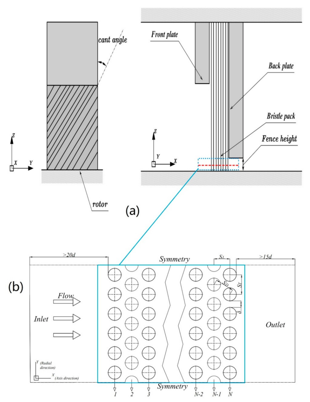
A brush seal is a flexible contact seal that includes the front plate, flexible bristle pack, and back plate, as shown in Figure 1a. The 2D tube bank model of staggered arrangement represents the plane section of X-Y (see the red line in Figure 1a), as shown in Figure 1b. In this paper, three different ratios of SD/d and five kinds of pressure difference are adopted to study dynamic pressure. In accordance with the characteristic of brush seal, the diameter of the bristles is set to 0.07 mm, and 6 rows of bristles are arranged in the Y-direction. From the first row of bristles near the inlet, the bristles are named from 1 to N. The computational domain must be expanded to address the extra velocity error caused by the boundary zone. The length from the inlet to the first row is 15 times the bristle’s diameter, and the length from the end row to the outlet is 20 times the bristle’s diameter, as shown in Figure 1b. The values of the geometry parameters [13] are given in Table 1, and the design equation is:
where d is the diameter of the bristles; δ is the gap between the bristles; ST is the longitudinal separation, and SL is the horizontal spacing.
2.2. Basic Assumptions of the Model
In this paper, the effect of pressure difference is considered for the bristle pack. The following assumptions are used to simplify the model based on the previous work [13] and the characteristics of the bristles:
- The bristles are assumed to be rigid. Therefore, aerodynamic force and rotor interference will not lead to the deformation and displacement of the bristles.
- The brush elements are arranged closely together in a regular hexagon with equal spacing.
- The pre-whirl effect is not considered, neither the effect of temperature. In other words, the operating temperature and the friction heat between rotor and bristles pack are ignored.
- When the cant angle is considered, the cross section of bristle is an ellipse. However, according to Zdravkovich [14], the flow around inclined cylinders is different from the flow around the elliptical cylinder. Therefore, the effect of the cant angle is ignored in the model.
3. Method
3.1. Grid Generation
In this paper, two different grids are used to establish the 2D tube bank model in GAMBIT. The unstructured grid is used in the zone of the bristle pack because of the complex construction, as shown in Figure 2a. Since the geometry of other zones is simple, a structured grid is enough. According to the grid independence test [15], 220 nodes are distributed on the surface of the bristles. The boundary sublayer thickness is 7 × 10⁻⁵ mm. The growth rate is 1.2, and the number of boundary layers is 4, as shown in Figure 2b.
3.2. Boundary Condition
The pressure boundary condition is used in the inlet and the outlet. The inflow boundary condition is the pressure inlet, and the outflow boundary condition is the pressure outlet. Also, according to the previous literature [16], the max bearing pressure ability of a brush seal is 0.5 MPa. The surface of the bristles is a no-slip wall, and the upper and lower boundaries are symmetric. The boundary conditions and the operating parameters are shown in Table 2.
3.3. Governing Equation and Solving Method
In this paper, the fundamental equations of compressible flow are used, under the rectangular coordinate system, they can be written as follows:
where P is the pressure of the working fluid, ρ represents the density of the working fluid, μ is the viscosity of the working fluid, and u and v are the velocity in the X- and Y-directions, respectively.
The working fluid satisfies the equation of state of ideal gas:
where R is the gas constant of the working fluid, and T is the temperature of the working fluid.
The standard k-ε model [17] is the most commonly used turbulence model. In the standard k-ε model, the Reynolds stress and time-averaged deformation rate have a linear relationship and are isotropic. However, in the real flow condition, the Reynolds stresses are coupled with each other, and the deformation of Reynolds stresses has a nonlinear relationship and is anisotropic. When the working fluid flows through the bristle pack, the streamline will bend and flow around a cylinder. Therefore, for the flow around cylinders that happened in the bush seal, the results of the standard k-ε model will cause larger errors compared with the physical truth. Compared with the standard k-ε model, the Renormalization Group (RNG) k-ε model [18] is more suitable for the condition of flow around cylinders. The RNG k-ε model can be expressed as follows:
where μt is the eddy viscosity coefficient, which can be obtained as follows,
where, Cμ = 0.085; Cε2 = 1.68; σk = σε = 0.719; C*ε1 = 1.42 − [Cμη3 (1 − η/4.38)]/(1 + 0.012η3); η is the time-averaged strain rate, η = kS/ε.
In this paper, the 2D staggered tube bank model is solved by using Fluent with a 2D steady-state solver based on the pressure base solver. SIMPLE [19] is used to solve the governing equation. The second-order upwind difference is used in the discretization schemes.
4. Results and Analysis
4.1. Model Verification
The working fluid flows through the clearance between rotor and back plate in the X-direction, and only little fluid flows through the bristle pack in the Z-direction. Therefore, the 2D tube bank model is reasonable. To justify the model, this paper compares the simulation data with the experimental data [20], as shown in Figure 3. P* is the dimensional normalization for the pressure P, and X* is the axis position of X,
where Xu is the coordinates of the upstream boundary, Xd is the coordinates of the downstream boundary, Pd is the pressure of the bristle pack downstream, Pu is the pressure of the bristle pack upstream, and ΔP is the pressure difference between upstream and downstream.
Figure 3 shows that the pressure drop is concentrated in the downstream of the bristle pack. CFD simulation results are similar to the experimental fitting curve. However, the results from the CFD simulation have some discrepancy with the experiment data because of the bristle oscillation.
4.2. State of Working Fluid in the Model
To study the velocity distribution and the density distribution of the gap, this paper extracts the simulation data of the midpoint of the gap centerline, as shown in points G and M in Figure 4a, and the results of the velocity change and density change in the bristle gap are shown in Figure 4b. The growth rate of velocity increases when the growth rate of density decreases. This change is described as index movement, which means that the flow is accelerated and expanded. According to conservation of mass, these finds can explain the reason for the accelerative flow which is found in Huang’s and Kang’s works [8,13]. Meanwhile, according to the polytropic process [21], the relationship between ρ and P satisfies the following equation:
where n is the polytropic exponent, and c is the constant. To investigate the flow in the bristle pack, according to Equation (9), the case in which SD/d = 1.10 and ΔP = 0.3 MPa, the results from the numerical simulation can be fitted as follows: P = 0.0788 × ρ1.057 (show in Figure 5).
This result shows that the value of n is greater than 1 but is less than the specific heat ratio (κ) of air of 1.402 [21], and it indicates that the state variation is between the isothermal process and the isentropic process, as shown in Table 3. However, the value is close to 1 as δ decreases, and when the value is equal to 1, the state variation becomes an isothermal process. The cause may be the flow path narrow and the fluid resistance increases.
4.3. Dynamic Pressure of the Bristle Pack
According to Equation (10), the density and velocity of gas also determine the value of dynamic pressure (D), as follows:
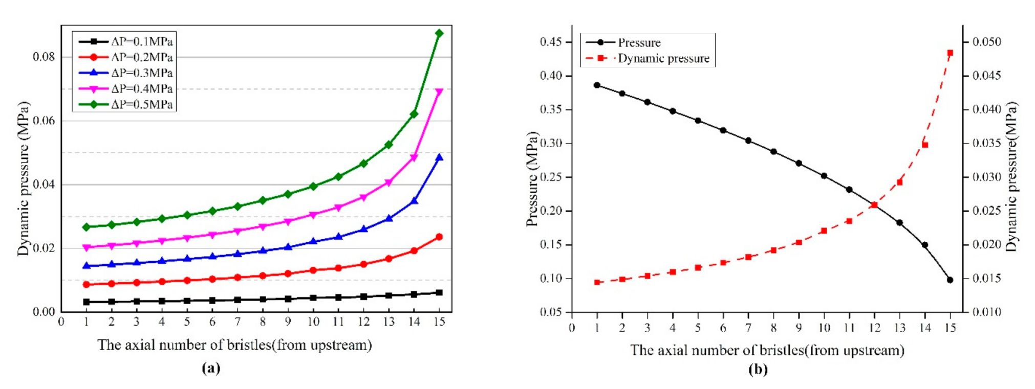
The dynamic pressure is an important physical quantity, since dimensionless parameterizations in the field of fluid mechanics are carried out by it, such as the pressure, drag, and lift of the cylinder surface. Furthermore, in the heat exchanger field, Eu, represents the energy loss of fluid, which can also be obtained from the dynamic pressure. The dynamic pressure may also cause vibration. For brush seals, the chatter of bristles may cause the fatigue failure of the welding spot of the bristle root. For example, Liu [11] studied the slippage of the upstream bristles with the dynamic head of the inlet swirl and found that the upstream bristles slipped when the dynamic head was bigger than 0.15 MPa. Since in this study the flow is compressible in the bristle pack, which is why the change of dynamic pressure is different from that of the heat exchangers. Figure 6a shows the dynamic pressure distribution of the bristle gap. The results show that the dynamic pressure increases as the row number increases. The differential pressure has a significant impact on dynamic pressure. As the ΔP increases, the dynamic pressure increases in every row, and the growth rate increases obviously in the downstream, indicating high kinetic energy and the strong impact of fluid on the bristles. As shown in Figure 6b, when the static pressure decreases, the dynamic pressure increases. This finding shows that the more pressure energy transforms into kinetic energy. Therefore, the mass flow rate will increase if the kinetic energy becomes larger.
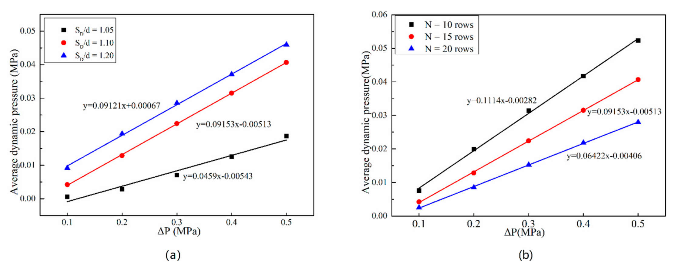
The spacing of the bristles and the number of rows of the bristles are important parameters for designing brush seals [22,23]. Three different spacing and three different numbers of tube rows are used to investigate the impact of these parameters. As shown in Figure 7a, δ has a significant impact on the dynamic pressure, and the dynamic pressure increases as the ΔP increases. Meanwhile, decreasing δ can reduce the dynamic pressure, that is, a small δ can effectively restrain the pressure energy transformation into kinetic energy. Curve fitting results show that the slope is 0.0459 when SD/d = 1.05, which is smaller than that of with other gaps. Therefore, under SD/d = 1.05, the fluid is blocked well.
The dynamic pressure distribution with different rows of bristles is shown in Figure 7b. The growth rate with 20 rows is 0.06422, which is lower than that of 10 and 15 rows, thereby indicating that the increase in bristle rows can suppress the increase in dynamic pressure. As the axial number of bristles increases, the dynamic pressure decreases, suggesting that the mass flow rate will decrease.
4.4. Euler Number of Bristle Pack
In fluid mechanics, the Euler number expresses the relationship between the loss of pressure and dynamic pressure, and it reflects the magnitude of the loss of momentum during the flow process. Kang [8] and Ma [24] introduce the Euler number for the evaluation of the seal performance in their studies, but they ignore the change of the density term. In their studies, the calculation formula of Euler number is as follows:
where Eu is the Euler number, ΔP is the differential pressure between the upstream and downstream, N is the number of rows in the X-direction, and Vu and Vexit are the velocities in the upstream and the gap of end row, respectively. As discussed in the previous section, the compressibility of the fluid can influence the dynamic pressure. Therefore, the equation needs to be amended to take this impact into account:
where Du and Pu are the dynamic pressure and the static pressure in the upstream, respectively; and Dexit and Pexit are the dynamic pressure and the static pressure in the gap of the end row, respectively.
For the tube bank model with different gaps, the area of the outlet is different, thereby potentially influencing the magnitude of the mass flux. Therefore, the mass flow rate can be compared using Equation (13) [25]:
The parameters are given in Lee [6]. NBcrf is the number of bristles per circumferential millimeter. α is the cant angle of bristle (Figure 1), α = 45°; FH is the fence height (Figure 1), FH = 1.075 mm; dr is the rotor diameter, dr = 180.05 mm; Q is the total leakage flow rate of the seal; m is the predicted flow rate of the tube bank model.
In accordance with Equation (12), Eu is studied in a bristle pack with different gaps, and the results are shown in Figure 8. In general, Eu decreases as the pressure difference increases. The average value of Eu for SD/d = 1.05, 1.10 and 1.20 is 2.594, 0.562 and 0.373. Therefore, when SD/d = 1.05, Eu is 4.62 times larger than that of the SD/d = 1.10 and 6.95 times larger than that of SD/d = 1.20, respectively. This finding indicates that the ability to convert pressure drop to dynamic pressure head is weaker than that of the SD/d = 1.10 and SD/d = 1.20 cases. According to thermodynamics [26], this phenomenon occurs because when 1 < n < κ shown in Table 3, the gas is heated and expanded, which indicates that the aerodynamic drag is not the main reason for kinetic energy consumption. In addition, when SD/d = 1.05, n is the lowest and close to 1. This means that the gas under SD/d = 1.05 condition is close to the isothermal process, and the pressure energy can transform more internal energy under the no-heat-exchange condition. This physical phenomenon is caused by the strong viscous resistance and interference drag in the small gap condition. As a result, the temperature of the SD/d = 1.05 case is higher than that of the others. When Eu decreases, the leakage rate increases, as shown in Figure 8.
Given that it maybe has the same viscous resistance and interference drag to block the fluid in the same gap, the total pressure loss Eu*N replaces Eu in the study of the relationship between row number and fluid blocking ability. The results are given in Figure 9, and it shows that Eu increases with the increasing numbers of rows. The average values of Eu*N of the 10-, 15-, and 20-row cases are 2.768, 8.432, and 12.581, respectively. The Eu*N of the 20-row case is 1. 5 times that of the 15-row case and 4.5 times that of the 10-row case, indicating that the 20-row bristle model is better at blocking fluid than the other models. The cause is increasing friction loss due to increasing flow path. Furthermore, the leakage rate decreases as the rows increase, as shown in Figure 9.
The gas flow can be retarded by increasing the number of bristle rows, and the magnitude of Eu at differential pressure from 0.1 to 0.2 MPa is Eu20 > Eu15 > Eu10. However, when the differential pressure is 0.3 MPa, the Eu values are sorted by magnitude changes to Eu10 > Eu20 > Eu15. The Eu value is Eu10 > Eu15 > Eu20 with the differential pressure increasing from 0.4 to 0.5MPa, as shown in Table 4. This shows that increasing the number of rows at low differential pressure can have a positive impact on the fluid. However, when the differential pressure becomes large, the ability to block the gas by increasing the number of brush wire rows will be reduced.
The analyses in this section indicate that Eu and Q have a negative correlation, that is, leakage rate is related to the ability to convert pressure loss into kinetic energy. When the value of Eu is high, and the ability to convert pressure loss into kinetic energy is weak. More energy will be converted into internal energy, thereby reducing the leakage rate.
4.5. Pressure Distribution on the Bristle Surface
The flow around the circular cylinders is studied with the non-dimensional coefficient [14] CP. The deformation equation is as follows:
where P0 is the stagnation pressure, Pθ is the pressure on the surface of the cylinder, and Vmax is the velocity in the gap between the bristles in the X-direction, which can be obtained due to the continuity equation as follows [27]:
where Vu is the velocity of the free stream. However, this equation is appropriate only for incompressible fluids because ρ is ignored. The gas is the compressible fluid in the brush seal as discussed in the previous sections. Therefore, Equation (15) is not beneficial in comparing the pressure distribution on the surface of bristles. In this paper, ρ is assumed to be homogeneous distributed in the bristle gap. According to the law of mass conservation, the equation of Vmax can be written as follows:
According to Equations (14) and (16), the formula of CP is then modified:
In addition, according to the conclusion of Section 4.2, the Equation (17) can be rewritten as follows:
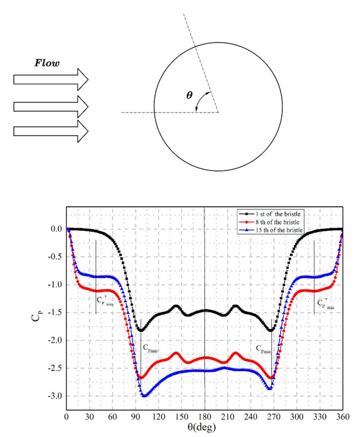
where ρ∞ is the density of the inlet, ρg is the density of the gap in each row, and Pg is the pressure in the gap between bristles. In accordance with the flow direction, θ is the angle of the pressure distribution on the surface, as shown in Figure 10. Equation (17) is suitable for the dimensionless formula in numerical simulation because the local density value is easy to obtain. However, it is difficult to obtain the local density value in reality, so Equation (17) can be replaced by Equation (18).
In this paper, the 15 rows with SD/d = 1.10 case is considered and ΔP is 0.3 MPa. The first, 8th and 15th row are studied because the pressure distributions in the second to 14th row are similar. The CP distributions for the chosen three rows are shown in Figure 10, and the following results can be obtained,
- The CP in the first and eighth rows of the bristles are symmetrical at about 180°. CPmin, the minimum pressure point, is located at 96° and the corresponding velocity is maximum. Then, an adverse pressure gradient appears, and the recirculation region is created at about 160°. In the region from 96° to 180°, the velocity decreases.
- C*Pmin, the local minimum pressure point, is located at 41° in the cylinder surface of the eighth and 15th rows. This phenomenon occurs because the fluid is accelerated in the gap between the bristle and the front bristle [14].
- In the end row, the pressure distribution is asymmetric due to jet deflection. The jet deflection is relevant to the value of ST/d. If ST/d is smaller than 2, then the neighboring bristles have an impact on the fluid. This effect is called nearby interference [14]. This jet deflection creates an aerodynamic force in the circumference direction, which leads to the oscillation in the end rows and the abrasion between the end row and the back plate. Meanwhile, the location of CPmin in the first row and the eighth row is 96°. The location of CPmin in the end row is 101°. The location of CPmin in the end row moves backward 5° compared with the other rows.
5. Conclusions
In this study, CFD simulation is used to study the density of fluid in the bristle pack. The gas state is discussed, and the dimensionless formula of Euler number and pressure is modified according to the work condition of brush seals. Based on fluid mechanics and thermodynamics, the conclusions are summarized in four important points:
- The gas is compressible in the bristle pack. The velocity increases as ρ decreases from the first row to the 15th row. According to the polytropic process, the fluid state is between the isothermal process and the isentropic process. The change in ρ is close to the isothermal process as δ decreases.
- The dynamic pressure is influenced not only by the velocity of fluid but also by the ρ of fluid. The dynamic pressure increases as ΔP increases, and the dynamic pressure increases with the number of rows. This phenomenon occurs because the pressure decreases from upstream to downstream. The number of rows and the magnitude of δ can influence dynamic pressure. The increase in the number of rows and the reduction of δ can prevent the dynamic pressure from increasing.
- Eu can represent the relationship between pressure drop and dynamic pressure. N and δ are important geometry parameters. The reduction of δ leads to the increase in Eu because more pressure energy transforms into internal energy. The increase in N is beneficial to the increase in Eu*N because of the added linear loss. If the Eu value is high, then the leakage rate is small.
- Considering the expansion of gas, the dimensionless formula is presented using the law of conservation of mass, which is beneficial to the comparison of bristles. Except for the end rows, the CP is symmetrically about 180°. Meanwhile, except for the first row, C*Pmin is present in the bristles because of the accelerating velocity in the gap between the adjacent rows. This phenomenon is different from that of the single circular cylinder. The asymmetry pressure distribution in the 15-row bristle surface is created by jet deflection. The aerodynamic force is created in the circumference direction, thereby aggravating the wear between the bristles and the back plate.
Author Contributions
Conceptualization, X.S., M.L., X.W. and J.S.; investigation, X.S. and J.S.; methodology, X.S. and M.L.; software, X.S.; resources, M.L.; data curation, X.S.; writing—original draft preparation, X.S., M.L. and X.H.; writing—review and editing, X.S., T.L. and X.H.; supervision, M.L. and X.H.; project administration, M.L. and J.S.; funding acquisition, M.L. All authors have read and agreed to the published version of the manuscript.
Funding
This research was funded by National Natural Science Foundation of China (grant number 51765024), and Analysis and Measurement Fund of Kunming University of Science and Technology (grant number 2020P20183103001).
Conflicts of Interest
The authors declare no conflict of interest. The funders had no role in the design of the study; in the collection, analyses, or interpretation of data; in the writing of the manuscript, or in the decision to publish the results.
Nomenclature
| d | Diameter of the bristles |
| ST | Longitudinal separation |
| SD | Diagonal spacing |
| SL | Horizontal spacing |
| P | Pressure of the working fluid |
| u | Velocity in the X- directions |
| v | Velocity in the Y-directions |
| R | Gas constant of the working fluid |
| T | Temperature of the working fluid |
| P* | Dimensional normalization for the pressure P |
| X* | Dimensional normalization for the axis position X |
| Xu | Coordinates of the upstream boundary in the X-direction |
| Xd | Coordinates of the downstream boundary in the X-direction |
| Pd | Pressure of the bristle pack downstream |
| Pu | Pressure of the bristle pack upstream |
| D | Dynamic pressure |
| ΔP | Differential pressure between the upstream and downstream |
| Eu | Euler number |
| N | Number of rows in the X-direction |
| Vu | Velocity in the upstream |
| Vexit | Velocity in the gap of end row |
| Du | Dynamic pressure in the upstream |
| Dexit | Dynamic pressure in the gap of the end row |
| Pexit | Static pressure in the gap of the end row |
| dr | Rotor diameter, dr = 180.05 mm |
| Q | Total leakage flow rate of the seal |
| m | Predicted flow rate of the tube bank model |
| CP | Non-dimensional pressure coefficient |
| CPmin | Minimum pressure coefficient |
| C*Pmin | Local minimum pressure coefficient |
| P0 | Stagnation pressure |
| Pθ | Pressure on the surface of the cylinder |
| Pg | Pressure in the gap between bristles |
| Vmax | Max average velocity in the gap between the bristles |
| n | The polytropic exponent |
Greek Symbols
| α | Cant angle of bristle (shown in Figure 1), α = 45° |
| δ | Gap between the bristles |
| ρ | Density of the working fluid |
| μ | Viscosity of the working fluid |
| μt | Eddy viscosity coefficient |
| η | Time-averaged strain rate, η = kS/ε |
| ρ∞ | Density of the working fluid in the inlet |
| ρg | Density of the working fluid in the gap of each row |
| θ | Angle of the pressure distribution on the surface |
Abbreviations
| CFD | Computational Fluid Dynamics |
| NBcrf | Number of bristles per circumferential millimeter |
| FH | Fence height (Figure 1), FH = 1.075 mm |
| RNG | Renormalization Group |
| SIMPLE | Semi-implicit method for pressure–linked equations |
References
- Baily, F.; Burnett, M.; Rivas, F.; Energy, G.E.; Bowsher, A.; Crudgington, P. Brush seals for improved steam brush seals for improved steam. IMechE Retrofit. Steam Power Gener. Plant. Semin. 2006, 1, 107–127. [Google Scholar]
- Miyake, K.; Duh, W.C. Leakage characteristics of brush mounted labyrinth seal with rotating speed. SAE Tech. Pap. 1998, 107. [Google Scholar] [CrossRef]
- Lee, J.J.; Kang, S.Y.; Kim, T.S.; Byun, S.S. Thermo-economic analysis on the impact of improving inter-stage packing seals in a 500 MW class supercritical steam turbine power plant. Appl. Therm. Eng. 2017, 121, 974–983. [Google Scholar] [CrossRef]
- Hildebrandt, M.; Schwarz, H.; Schwitzke, C.; Bauer, H.-J.; Friedrichs, J. Effects of the back plate inner diameter on the frictional heat input and general performance of brush seals. Aerospace 2018, 5, 58. [Google Scholar] [CrossRef] [Green Version]
- Li, J.; Obi, S. Numerical investigations on leakage flow characteristics of labyrinth brush seals at the turbine blade shroud. In Proceedings of the Proceedings of the Computational Mechanics Conference, Okinawa, Japan, 1–3 November 2008; pp. 822–823. [Google Scholar]
- Lee, K.H.; Ha, T.W. Analysis of hybrid brush seal rotordynamic coefficients according to position of brush and clearance using 3D CFD. Int. J. Fluid Mach. Syst. 2020, 13, 90–102. [Google Scholar] [CrossRef]
- Kudriavtsev, V.V.; Braun, M.J. Model developments for the brush seal numerical simulation. J. Propuls. Power 1996, 12, 193–201. [Google Scholar] [CrossRef]
- Kang, Y.; Liu, M.; Kao-Walter, S.; Reheman, W.; Liu, J. Predicting aerodynamic resistance of brush seals using computational fluid dynamics and a 2-D tube banks model. Tribol. Int. 2018, 126, 9–15. [Google Scholar] [CrossRef] [Green Version]
- Fuchs, A.; Haidn, O.J. Effects of uncertainty and quasi-chaotic geometry on the leakage of brush seals. J. Turbomach. 2019, 141, 1–9. [Google Scholar] [CrossRef] [Green Version]
- Sharatchandra, M.C.; Rhode, D.L. Computed effects of rotor-induced swirl on brush seal performance—Part 2: Bristle force analysis. J. Tribol. 1996, 118. [Google Scholar] [CrossRef]
- Liu, Y.; Chew, J.W.; Pekris, M.J.; Kong, X. The effect of inlet swirl on brush seal bristle deflections and stability. J. Eng. Gas. Turbines. Power 2020, 142, 249–255. [Google Scholar] [CrossRef]
- Wiid, J.J.F. The experimental and Numerical Investigation of the Influence of Shaft Rotation on Leakage Rate of Non-contacting Seals Found in Turbine Applications. Ph.D. Thesis, University of Pretoria, Pretoria, South Africa, 2018. [Google Scholar]
- Huang, S.; Suo, S.; Li, Y.; Yang, J.; Liu, S.; Wang, Y. Flows in brush seals based on a 2-D staggered tube bundle model. J. Tsinghua Univ. 2016, 56, 160–166. [Google Scholar] [CrossRef]
- Zdravkovich, M.M. Flow around Circular Cylinders; Oxford Science Publications: Oxford, UK, 1997; ISBN 0198563965. [Google Scholar]
- Tan, Y.; Liu, M.; Kang, Y.; Wang, X.; Liu, J. Investigation into brush seal vortex separation point based on 2D staggered tube bundle model. J. Drain. Irrig. Mach. Eng. 2017, 35, 602–608. [Google Scholar] [CrossRef]
- Nakane, H.; Maekawa, A.; Akita, E.; Akagi, K.; Shinohara, T.; Uehara, H. The development of high performance leaf seals. In Proceedings of the 47th International Gas Turbine and Aeroengine Congress and Exhibition, Amsterdam, the Netherlands, 3–6 June 2002; Volume 126, pp. 342–350. [Google Scholar]
- Launder, B.E.; Spalding, D.B. The numerical computation of turbulent flows. Comput. Methods. Appl. Mech. Eng. 1974. [Google Scholar] [CrossRef]
- Yakhot, V.; Orszag, S.A.; Thangam, S.; Gatski, T.B.; Speziale, C.G. Development of turbulence models for shear flows by a double expansion technique. Phys. Fluids. A 1992, 4, 1510–1520. [Google Scholar] [CrossRef] [Green Version]
- Patankar, S.V.; Spalding, D.B. A calculation procedure for heat, mass and momentum transfer in three-dimensional parabolic flows. Int. J. Heat. Mass. Transf. 1972, 54–73. [Google Scholar] [CrossRef]
- Bayley, F.J.; Long, C.A. A combined experimental and theoretical study of flow and pressure distributions in a brush seal. J. Eng. Gas. Turbines Power 1993, 1, 1–9. [Google Scholar] [CrossRef]
- Franzini, J.B. Fluid Mechanics with Engineering Applications, 9th ed.; McGraw-Hill: New York, NY, USA, 2011. [Google Scholar]
- Pekris, M.J.; Franceschini, G.; Gillespie, D.R.H. Effect of geometric changes in an idealised contacting brush seal bristle pack on typical key performance measures. In Proceedings of the ASME Turbo Expo, Vancouver, BC, Canada, 6–10 June 2011; pp. 999–1010. [Google Scholar]
- Fuchs, A.; Gottler, J.; Haidn, O.J. Numerical investigation on the leakage of brush seals. In Proceedings of the Proceedings of Montreal 2018 Global Power and Propulsion Forum, Montreal, QC, Canada, 7–9 May 2018; pp. 1–8. [Google Scholar]
- Ma, D.; Zhang, Y.; Li, Z.; Li, J.; Yan, X. Applying Three-Dimensional Staggered Tube Bundle Model to Investigate the Leakage Flow Characteristics of Brush Seals. J. XI’AN JIAOTONG Univ. 2020, 54, 72–80. [Google Scholar] [CrossRef]
- Demiroglu, M.; Aksit, M.F.; Tichy, J.A. A numerical study of brush seal leakage flow. In Proceedings of the 34th AIAA/ASME/SAE/ASEE Joint Propulsion Conference and Exhibit, Cleveland, OH, USA, 13–15 July 1998; pp. 1–8. [Google Scholar]
- Cengel, Y.A.; Boles, M.A. Thermodynamics: An Engineering Approach, 8th edition; McGraw-Hill: New York, NY, USA, 2015; ISBN 9788578110796. [Google Scholar]
- Singh, P.C.; Henneke, M.; Jayakaran, J.D.; Hayes, R.; Baukal, C.E. Heat transfer. In The John Zink Combustion Handbook; CRC Press: Boca Raton, FL, USA, 2001; ISBN 9781420038699. [Google Scholar]
Figure 1.
Schematic of a brush seal. (a) The structure of a brush seal; (b) the 2-D staggered tube banks model.
Figure 1.
Schematic of a brush seal. (a) The structure of a brush seal; (b) the 2-D staggered tube banks model.

Figure 2.
Grid generation of the 2D tube bank model. (a) represents the structured grid in upstream and downstream. (b) represents the unstructured grid and the boundary layer mesh in bristles pack.
Figure 2.
Grid generation of the 2D tube bank model. (a) represents the structured grid in upstream and downstream. (b) represents the unstructured grid and the boundary layer mesh in bristles pack.

Figure 3.
Comparison of the predicted and Bayley and Long’s pressure distributions [20].
Figure 3.
Comparison of the predicted and Bayley and Long’s pressure distributions [20].

Figure 4.
Data collection points (a) and the change of velocity and density (b) at ΔP = 0.3 MPa and SD/d = 1.10, where the points of G and M are the data collection points in (a).
Figure 4.
Data collection points (a) and the change of velocity and density (b) at ΔP = 0.3 MPa and SD/d = 1.10, where the points of G and M are the data collection points in (a).

Figure 5.
The curve fitting according to the polytropic process.

Figure 6.
The dynamics pressure distribution of SD/d = 1.10 case. (a) The effect of differential pressure; (b) the relationship between pressure and dynamic pressure at ΔP = 0.3 MPa.
Figure 6.
The dynamics pressure distribution of SD/d = 1.10 case. (a) The effect of differential pressure; (b) the relationship between pressure and dynamic pressure at ΔP = 0.3 MPa.

Figure 7.
The average dynamics pressure with different SD/d (a) and different rows (b). The number of axis rows is 15 rows in (a), and the magnitude of SD/d = 1.10 in (b).
Figure 7.
The average dynamics pressure with different SD/d (a) and different rows (b). The number of axis rows is 15 rows in (a), and the magnitude of SD/d = 1.10 in (b).

Figure 8.
Euler number Eu and leakage rate Q with different gaps. The left axis of Q represents the leakage rate, shown in solid lines, and the right axis of Eu represents Euler number, shown in dotted lines.
Figure 8.
Euler number Eu and leakage rate Q with different gaps. The left axis of Q represents the leakage rate, shown in solid lines, and the right axis of Eu represents Euler number, shown in dotted lines.

Figure 9.
Eu*N and leakage rate Q with different rows. The left axis of Q represents the leakage rate, shown in solid lines, and the right axis of Eu*N represents the total pressure loss, shown in the dotted lines.
Figure 9.
Eu*N and leakage rate Q with different rows. The left axis of Q represents the leakage rate, shown in solid lines, and the right axis of Eu*N represents the total pressure loss, shown in the dotted lines.

Figure 10.
The distribution of CP on the bristle surface.


Table 1.
Geometry parameters of the simulation model.
| SD/d | δ [mm] | ST [mm] | SL [mm] |
|---|---|---|---|
| 1.05 | 0.0035 | 0.0735 | 0.0637 |
| 1.10 | 0.0070 | 0.0770 | 0.0667 |
| 1.20 | 0.0140 | 0.0814 | 0.0728 |
Table 2.
Operating parameters.
| Parameter | Magnitude |
|---|---|
| Working fluid | Ideal gas |
| Pressure inlet [MPa] | 0.201, 0.301, 0.401, 0.501, 0.601 |
| Pressure outlet [MPa] | 0.101 |
| Temperature [K] | 300 |
Table 3.
Value of n with different ΔP and SD/d, where n is the polytropic exponent in the thermodynamics; ΔP is the differential pressure between Inlet and Outlet.
Table 3.
Value of n with different ΔP and SD/d, where n is the polytropic exponent in the thermodynamics; ΔP is the differential pressure between Inlet and Outlet.
| ΔP [MPa] | SD/d | ||
|---|---|---|---|
| 1.05 | 1.10 | 1.20 | |
| 0.1 | 1.002 | 1.014 | 1.040 |
| 0.2 | 1.007 | 1.037 | 1.068 |
| 0.3 | 1.016 | 1.057 | 1.079 |
| 0.4 | 1.025 | 1.067 | 1.083 |
| 0.5 | 1.032 | 1.073 | 1.085 |
Table 4.
The Eu value of 10 rows, 15 rows, 20 rows bristles, where EuN is the Euler number of N-row case; ΔP is the differential pressure between Inlet and Outlet.
Table 4.
The Eu value of 10 rows, 15 rows, 20 rows bristles, where EuN is the Euler number of N-row case; ΔP is the differential pressure between Inlet and Outlet.
| ΔP [MPa] | EuN | ||
|---|---|---|---|
| Eu10 | Eu15 | Eu20 | |
| 0.1 | 0.937 | 1.097 | 1.360 |
| 0.2 | 0.571 | 0.573 | 0.632 |
| 0.3 | 0.482 | 0.419 | 0.440 |
| 0.4 | 0.456 | 0.372 | 0.368 |
| 0.5 | 0.438 | 0.350 | 0.345 |
Publisher’s Note: MDPI stays neutral with regard to jurisdictional claims in published maps and institutional affiliations. |
© 2021 by the authors. Licensee MDPI, Basel, Switzerland. This article is an open access article distributed under the terms and conditions of the Creative Commons Attribution (CC BY) license (http://creativecommons.org/licenses/by/4.0/).
Share and Cite
MDPI and ACS Style
Song, X.; Liu, M.; Hu, X.; Wang, X.; Liao, T.; Sun, J. Numerical Analysis of Flow across Brush Elements Based on a 2-D Staggered Tube Banks Model. Aerospace 2021, 8, 19. https://0-doi-org.brum.beds.ac.uk/10.3390/aerospace8010019
AMA Style
Song X, Liu M, Hu X, Wang X, Liao T, Sun J. Numerical Analysis of Flow across Brush Elements Based on a 2-D Staggered Tube Banks Model. Aerospace. 2021; 8(1):19. https://0-doi-org.brum.beds.ac.uk/10.3390/aerospace8010019
Chicago/Turabian StyleSong, Xiaolei, Meihong Liu, Xiangping Hu, Xueliang Wang, Taohong Liao, and Junfeng Sun. 2021. "Numerical Analysis of Flow across Brush Elements Based on a 2-D Staggered Tube Banks Model" Aerospace 8, no. 1: 19. https://0-doi-org.brum.beds.ac.uk/10.3390/aerospace8010019
Note that from the first issue of 2016, this journal uses article numbers instead of page numbers. See further details here.