
A Numerical Investigation on Stress Modal Analysis of Composite Laminated Thin Plates


College of Civil Aviation, Nanjing University of Aeronautics and Astronautics, #29 Jiangjun Ave., Nanjing 211100, China
*
Author to whom correspondence should be addressed.
Aerospace 2021, 8(3), 63; https://0-doi-org.brum.beds.ac.uk/10.3390/aerospace8030063
Submission received: 27 December 2020
/
Revised: 11 February 2021
/
Accepted: 24 February 2021
/
Published: 4 March 2021
(This article belongs to the Special Issue Crashworthiness Design for Aviation Safety)
Abstract
:Because of the light weight and high strength, composite laminates have many advantages in aircraft structures; however, they are frequently subjected to severe dynamic loadings during flight. To understand the dynamic properties of composite laminated thin plates at the stress scale, this paper studies the stress modal analysis (SMA) of composite laminated thin plates by finite element method (FEM). Firstly, the basic theory on SMA of composite laminates was given from the classical displacement modal analysis. Secondly, a square laminated thin plate was numerically studied to obtain some distribution laws of the stress mode shapes (SMSs) from the layup and stress component perspectives. Then, based on the characteristics of SMSs in different plies, a modified layup configuration was conducted for possible lower magnitude and more uniform distributions of SMSs. Results indicate that ±45° layups can improve the performance of SMSs of the square plate, without excessively decreasing the modal frequencies. Such fact manifests that ±45° layups are critically vital for the dynamic stress reduction of the square composite laminated plates. Modal participation factor and strain energy were evaluated to assist the determination of critical modes. Lastly, the aspect ratio of the composite plate on layup design was considered. Numerical investigation in this study can serve as a preliminary step of SMSs perspective for the analysis and optimization of dynamic composite laminates.
1. Introduction
Mechanics of composite laminates have been researched for decades [1], mainly due to their advantages in high specific strength, better fatigue/impact resistance and weight reduction, etc. The dynamic aspects of composite laminated plates have been remaining the hot topics for the airworthiness of aircraft structures, such as the composite laminated wing/skin systems and composite fan blades. The vibration properties, dynamic response and damage assessment of composite laminated structures [2,3,4,5,6,7,8,9,10] are of critical importance for the real applications of aircraft structures, which are susceptible to severe dynamic loadings during flight. The safety consideration of these aircraft laminated structures needs to deeply understand their dynamic properties, so as to identify and assess their operating conditions, and hence the airworthiness requirements can be verified [6]. Among the inherent characteristics of the dynamic structures, modal properties (e.g., modal frequencies and mode shapes), play a vital role in observation of the dynamic behaviour of mechanical structures. Modal properties of composite material systems contain rich potential global/local information for dynamic structural identification [2,11]. Meanwhile, the structural parameters of composite laminated plates (e.g., the ply orientation, aspect ratios, cutouts, etc.) always act as important roles in determination of the inherent modal properties and dynamic behaviours [12,13,14,15,16,17].
For general dynamic structures with metallic or composite materials, classical modal analysis [18,19,20] has been of critical importance to facilitate the structural numerical modelling [21,22], response/damage prediction [23,24], vibration fatigue evaluation [25,26,27], and structural dynamic design [28], etc. In modal analysis, local identification of structural systems is crucial for damage detection and dynamic modelling. As for the modal analysis of plate-type structures, the structural characteristic deflection shapes or their spatial derivatives are critically important for damage localization [29,30,31]. One the one hand, by avoiding the use of traditional acceleration sensors with excessive self weight, strain sensors are more favourable for light-weight thin-walled structures; on the other hand, strain mode shapes and strain responses can provide important data for dynamic modelling, identification and structural health monitoring. Consequently, due to the local properties and information benefitted from the spatial second derivative, strain mode shapes are highly sensitive parameters to local structural change and damage in flexural vibrations [20,32,33,34,35]. It was confirmed [36,37] that dynamic displacements can be estimated using dynamic strain data without displacement measurement, where the strain mode shapes can be directly estimated from the measured strains [38]. Such features facilitate the full displacement/strain field reconstruction from measured strain modes. However, towards structural remaining useful life, the stress frequency response function (SFRF) is highly required in many cases for dynamic stress estimation, such as estimating a structure’s fatigue life during vibration [39]. Correspondingly, stress modal analysis (SMA) have achieve vital advances in recent years, such as the dynamic response calculation [40,41] and vibration fatigue evaluation [42,43,44] of isotropic materials. In particular, utilization of stress modal approach into aircraft thin-walled structures with large numbers of joint holes or notches [45,46] and local refinement of numerical model [47] can be of computationally efficiency; however, these SMA studies mainly focused on metallic structures. To handle the modal properties of composite structures, Lestari et al. [48] and Qiao et al. [49] conducted the curvature mode shape-based damage assessment of carbon/epoxy composite beams and plates, which indicated discontinuities of the curvature modes due to the presence of damage. Frieden et al. [50] experimentally obtained the first four strain mode shapes of a clamped CFRP composite plate. Shariyat et al. [51] developed a semi-analytical solution for free vibration and modal stress analyses of two-dimensional functionally graded circular plates. dos Santos et al. [52] conducted strain modal test on the carbon fiber composite plate with a stacking sequence of [0°/90°/0°/90°/0°/90°/0°], and the correlations between the tested and the simulated strain modes were studied. Yang et al. [53] and Ooijevaar et al. [54] respectively conducted the two-dimensional modal curvature estimation for composite structures. For the purpose of structural health monitoring of composite sandwich panels, Loutas and Bourikas [55] utilized strain mode shapes from two directions simultaneously (instead of accelerations or displacements) for the optimal sensor placement. By using a proposed higher-order zig-zag theory, Wu and Chen [56] evaluated the modal transverse shear stress through the thickness of a four-layer [0°/90°/90°/0°] beam. More recently, Esposito and Gherlone [57] reconstructed the displacement field of a composite wing box via measured strain modes. It can be seen that these works have shown the useful applications of strain-related modal techniques for advanced composite structures.
With the continuous development of numerical methods and software, on the one hand, vibration aspects of laminated composite plates can be efficiently investigated by numerical simulations, e.g., finite element method (FEM) for composite materials [58,59,60]. Up to now, extensive studies have been conducted on the free vibration analysis of composite laminated plates [61,62,63,64,65,66,67,68], which have given insights into accurate descriptions of the complicated displacement fields of the natural vibration, i.e., the displacement mode shapes (DMSs). On the other hand, because of the complex micro architecture, composite materials themselves can be considered as a kind of complex structure. Failure and damage analyses of complex composite laminates and structures require us to capture the structural local properties, e.g., via the framework of FEM [69]. Furthermore, in the case of static analysis, the invariant-based “master ply” approach [70] and the CUF-based (Carrera Unified Formulation) approach [71] were developed towards the local stress recovery for composite laminated structures, which have indicated excellent accuracy and efficiency for local static stress. Local dynamic stress will be also crucial for structural dynamics of composite structures. Consequently, towards the dynamic structural identification at the stress scale, it is highly necessary to shed light on their stress modal properties for structural assessment under vibrations. For example, for the purpose of dynamic failure analysis, the stress distribution in each layer is crucial. However, to the best of authors’ knowledge, although the global modal properties of composite structures have been widely researched, the stress mode shapes (SMSs) of composite laminates have been relatively less investigated in computational structural dynamics, which will be potentially useful for dynamic modelling and damage assessment. The previous focus of SMSs research was mainly developed for vibrating structures made of isotropic materials. Furthermore, in the present strain modal analyses for composite laminates, only the surface strain distributions were measured or calculated. However, the layer-wise strain/stress distributions are required for structural damage assessment (e.g., the envelope damage for load-carrying capability assessment). Therefore, the aim of present work is to numerically obtain some basic laws for the SMSs of composite laminates for future potential use in the dynamic stress response calculation and damage evaluation. The preliminary innovative point of present study is to consider the SMSs of composite laminates from different dimensions. The outline of this paper is as follows. Section 2 presents the basic theory for SMA of composite laminates. Section 3 concisely describes the FEM modelling. In Section 4, the numerical results are analysed and discussed. Section 5 draws some conclusions.
2. Theoretical Background
As mentioned in the introduction section, strain mode shapes already have indicated some special advantages over classical DMSs for specific applications. Nevertheless, some particular situations make stress mode shapes (SMSs) more promising in computational structural dynamics. It can be enumerated that at least three aspects make it necessary to further study the SMSs of composite laminated plates:
- Dynamic stress responses are straightforward related to material’s strength, e.g., in the criteria of vibration fatigue under random loadings [72]; and vibration fatigue failure of aircraft composite materials is frequently stress-induced high-cycle fatigue;
- Although the displacement fields of composite laminates are continuous, the stress distribution of each lamina may experience severe discontinuity due to the severe anisotropy. The SMSs can embody the orientation effect of each lamina, i.e., the same strain along different directions may result in different stresses because of the orthotropic properties;
- The strain modes measured at laminate’s surface in modal testing cannot reflect the internal stress state at a mode shape; while the internal SMSs can be easily captured in computational modal analysis, which will be useful for internal damage assessment for each layer.
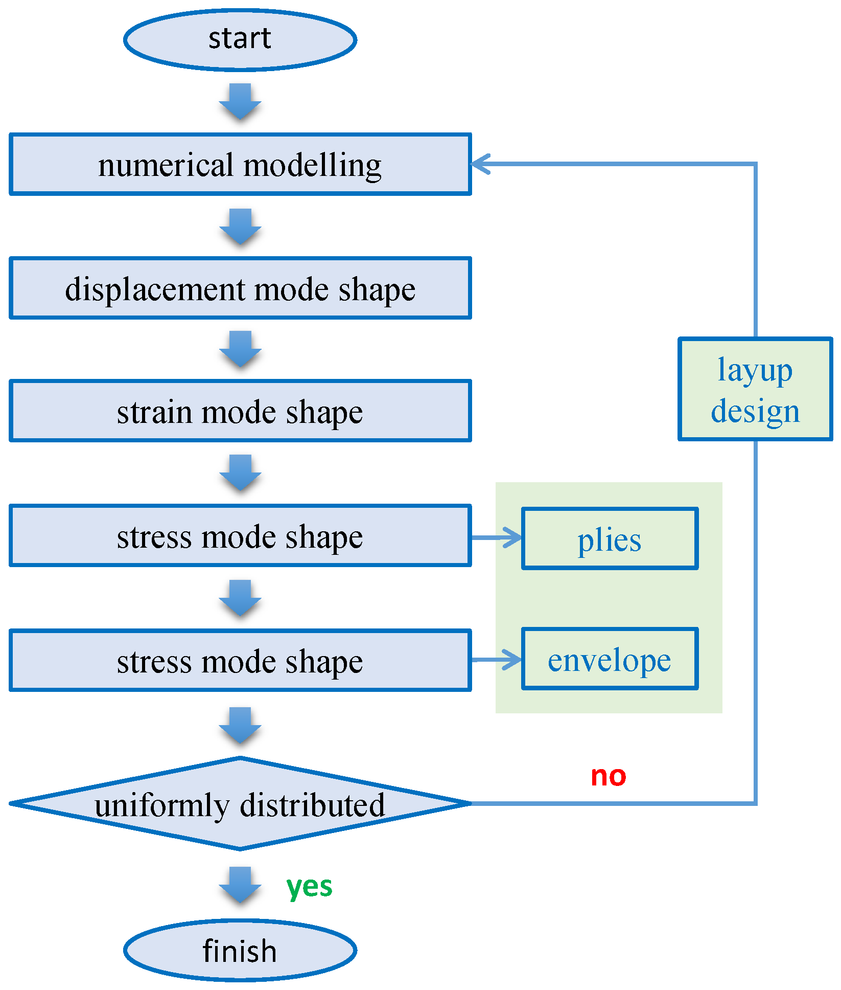
In light of these aspects, this section introduces some basic theory by transferring from displacement and strain modes to stress modes for composite laminated plates. The flowchart is as shown in Figure 1, which starts with the analytical functions or numerical models to obtain the DMSs, ends with the envelope SMSs of each ply. In the design loop, the uniformly-distributed SMSs can be considered as the criterion for the purpose of failure resistance. The more uniformly-distributed SMSs can lead to reduced local stress concentration from the perspective of structural dynamics. Therefore, the results of envelope SMSs are highly critical to evaluate the layups of composite laminates. Once the degree of uniformity is satisfactory, the designer can exit from the loop and move on to the verification of failure/crashworthiness analysis under a certain dynamic excitation.
A continuous structural system can be discretized into a system with multiple degrees of freedom (DOFs), by utilizing FEM, and the second-order differential motion equation in the time domain of the discretized system is
where , and are the mass, damping, and stiffness matrices of the system with N DOFs, respectively; x is nodal displacement vector and f is the exciting force vector applied to the system. The matrices of structural physical properties M, D, K can be assembled in the FEM discretization. In the frequency domain, the motion equation is
where j is the imaginary unit. The traditional computational modal analysis is a classical matrix eigenvalue problem. Under the assumption of light damping that can be neglected, eigenvalue problem can be reduced to solve the matrix determinant , from which the N modal frequencies can be calculated. That is, the modal frequencies are calculated via a global stiffness and mass matrices. Then, the eigenvector represents the inherent vibration form (relative displacements) of the corresponding eigenvalue. The full eigenvectors comprise the modal matrix . With the aid of modal coordinate , the displacement modal decomposition in the time domain gives . In the frequency domain, the displacement frequency response function (DFRF) can be described by the modal parameters as [18]
where n is the reduced mode number; kr, mr, and cr denote the rth modal stiffness, modal mass and modal damping, respectively. The above equations are the general theory applicable to both metallic and composite structures. Herein, let us consider the free vibration of a rectangular composite plate (a × b × h). The classical laminated plate theory is an extension of the Kirchhoff (classical) plate theory to laminated composite plates, of which the displacement field has
where (u0, v0, and w0) are the elastic displacement components along the (x, y, z) coordinate directions of a point on the mid-plane (i.e., z = 0), respectively. Generally, the z-axis is aligned along the thickness direction (transverse direction) for thin plates. The Kirchhoff assumption indicates that the deformation is entirely due to bending and in-plane stretching, which agrees well with the thin plate case, so that it is assumed in this preliminary investigation. In free vibration analysis, the mode shape function at a point can be expressed by a series as [1]
where m and n are the numbers of the used functions in each direction. Detection of damage locations in plate-like metallic and sandwiched structures based on the changes in modal strain energy has been well established and applied [73,74], which is in nature related to the change in the curvature mode shapes (CMSs). CMSs have recently been investigated as a promising feature for damage identification [75]. Analytically, the modal curvature vector of thin plates can be defined as
It can be seen that CMSs are evaluated by the second-order differentiation of the DMSs. Numerically, CMSs can be calculated by a central difference approximation: , where ϕi is the DMSs at i-th grid point in structure, d is the distance between neighbouring grid points. Once the modal curvatures are obtained, some useful resultant quantities can be derived, e.g., modal strain energy during the elastic deformation of laminated plates can be calculated as [76]:
where the coefficients Dik are the bending stiffness. In light of the strain–displacement relationship of an elastic thin plate, the strain mode shape can be defined as the distribution of the in-plane strain components at the top or bottom surface of the plate according to the corresponding natural vibration mode. Such definition can facilitate the strain measurement for a manufactured structure, which is an advantage of strain modal testing. For example, the local surface strains at a mode shape in the x and y directions can be expressed as [52]
where δ is the distance between the neutral plane and the surface. It can be seen that both the strain and curvature modes are based on the deformation relationship. Now, let us deal with composite materials, of which the constitutive relations are different from isotropic materials. Generalized Hook’s law for an elastic anisotropic material is a linear stress–strain constitutive relationship, defined by
where σ is the macro stress vector, ε is macro strain vector, C is elastic matrix and S = C−1 is the compliance matrix. Composite laminates can be made of unidirectional laminas, plain-woven laminas, or twill-woven laminas, etc. For simplicity but not to lose generality, herein this study considers the unidirectional lamina for the composite laminates. The main difference from the isotropic material the orientation-dependant material property. Furthermore, the unidirectional lamina falls within the orthotropic material category. In this study, consider the laminated plates with the following assumptions:
- (a)
- The thickness distribution of the plate is uniform.
- (b)
- The material is linear elastic and 2-D orthotropic.
- (c)
- The damping is light, so that it can be neglected.
If the lamina (i.e., one layer) is thin and does not carry any out-of-plane loads, one can assume plane stress conditions for the lamina. The stress–strain relationship can then be written as
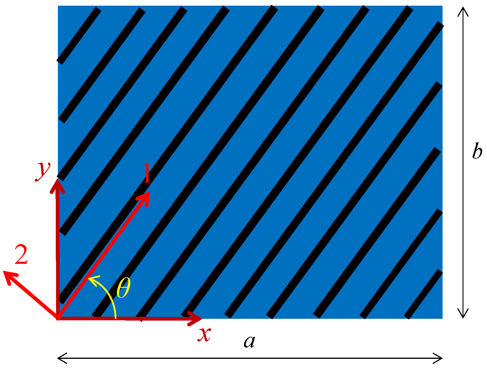
The choice of coordinate system for the laminated plate will determine its layup (stacking sequence). A coordinate system used for showing an angle of the lamina is given in Figure 2. The axes in the 1–2 coordinate system are called as the local axes or the material axes. The direction 1 is parallel to the fiber and the direction 2 is perpendicular to the fiber.
The off-axis stress–strain relationship under the plane stress field can be expressed as
where c = cos θ and s = sin θ. This relation can be abbreviated as
where T is the transformation matrix. Apparently it has . Now that all plies have an angle associated with the coordinate system, therefore, it can be concluded that the SMSs in each ply will be different with each other, though they share the same deflections in DMSs under the assumption of constant displacement across the thickness [61]. Such fact is different from isotropic plates, where the maximum stress always appears at the surfaces.
Similar with the dynamic displacement responses for linear systems, the modal superposition theory can be used to describe the dynamic stress response as a summation of the rth SMSs () weighted by the rth modal coordinate (qr) in the time domain
where m is the number of considered modes. It should be mentioned that in Equation (14) denotes the dynamic stress response in a general sense, which represents an arbitrary stress component or a stress invariant. A mapping relationship exists between and , such as for thin plates. Further, dynamic stress response in the frequency domain can be expressed by using the stress frequency response function (SRFR) . For example, the unsteady aerodynamic loading and the aero-acoustic loading are random excitations on the panel surfaces of aircraft structures. The dynamic stress response under random excitations can be calculated by
where the matrices and are the power spectral density (PSD) functions of dynamic excitation and stress response, respectively. Further, the stress PSD has different directions and resultant quantities. Equation (15) is tenable for both the isotropic and composite materials as long as the SFRF is obtained. As one of the inherent properties, the SFRF is determined by SMSs in nature. Therefore, the random stress responses in the frequency domain are determined by the input excitation and SMSs together. It can be concluded that optimal SMSs can achieve stress response reduction, and hence the local excessive stress concentration can be alleviated for dynamic composite structures.
3. FEM Modelling
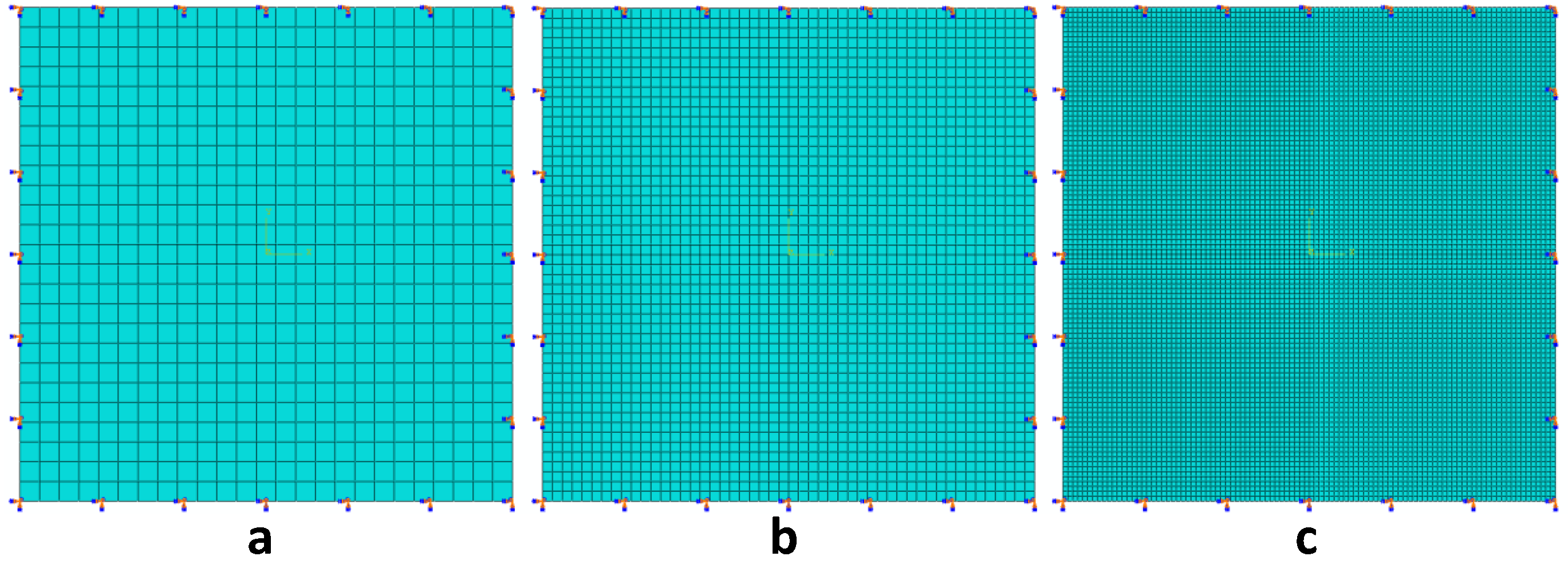
For simplicity, but without loss of generality, a square laminated thin plate with clamped boundary condition was considered for present case study at first. Each ply can be modelled as a linear, elastic, orthotropic material. For composite laminates in aerospace structures, the ratio can reach higher than 10, e.g., the graphite/epoxy lamina. In light of this fact, the mechanical properties of a CFRP lamina are used here, of which the values are the same with previous crashworthiness study for composite laminates [77]. The initially considered layup was [0°/45°/0°/−45°]s, using 0.15 mm thick unidirectional lamina, which are illustrated in Figure 3. The modelling technique of composite layup was used to build the laminated plate, where each ply is composed of a homogenous material of uniform thickness, with fibers oriented along a single orientation. Although dozens or even hundreds of layers may be used in real application, this study considered the eight-ply plate as the demonstration, which does not affect the mechanism investigation of SMSs in composite laminates. The layers were modelled by using quadrilateral shell element (S4R), which is characterized by four-node doubly curved thin or thick shell, reduced integration, hourglass control, finite membrane strains. Table 1 lists the material properties of the unidirectional lamina. To verify the accuracy of FEM model, three different FEM meshes of the square laminated thin plate were considered: (a) coarse mesh with 25 × 25 elements, (b) moderate mesh with 50 × 50 elements, and (c) dense mesh with 100 × 100 elements. Figure 4 presents the FE meshes together with schematic representation of the clamped boundary condition, i.e., constraining all of the six degrees of freedom at each edge of the plate. Figure 5 plots the first 20 modal frequencies via three different FE meshes. It can be seen that the moderate mesh with 50 × 50 elements can achieve the satisfactory results. Therefore, the selected mesh size was 10 mm × 10 mm on the square plate and a total of 2500 elements was used in the following analysis. The Lanczos algorithm has been utilized to obtain the eigenvalues and eigenvectors.
4. Results and Discussion
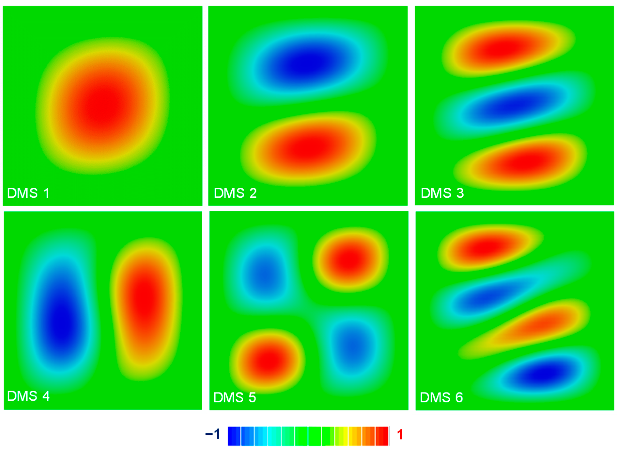
To compare each normal mode, it is critical to apply the same normalization method to the mode shapes. Herein, the displacement normalization was selected. Although the DMSs of square laminated thin plates are well-known, for the convenience of comparison, the first six DMSs are plotted as Figure 6, which are smoothly distributed as expected. And obviously, in each mode, the deflection of an arbitrary location (x, y) under the mode shape shares the same deflection value for each layup. Even though a delamination appears, DMSs cannot reflect it because the delamination is generally much small distance in a micro scale.
To explain the results of SMSs as given in Figure 7, two aspects should be clarified:
- (1)
- The stress mode distributions in different laminas will be different due to the orthotropic elastic properties. Because the maximum damage envelope of all layers is critically important in evaluating the strength of laminated plates (e.g., in the failure criteria of damage mechanics); therefore, herein, the envelope SMSs are considered.
- (2)
- The SMSs have different distributions with different stress components (e.g., for thin plates along the three important directions) and the invariants. For simplicity but without loss of generality, present study only considers the in-plane stresses, which are the most important stress components in damage criteria of composite laminates. For instance, the Tsai–Hill failure criterion can be written as , for the multi-axial random stress states (plane stress) in composite structures [78].
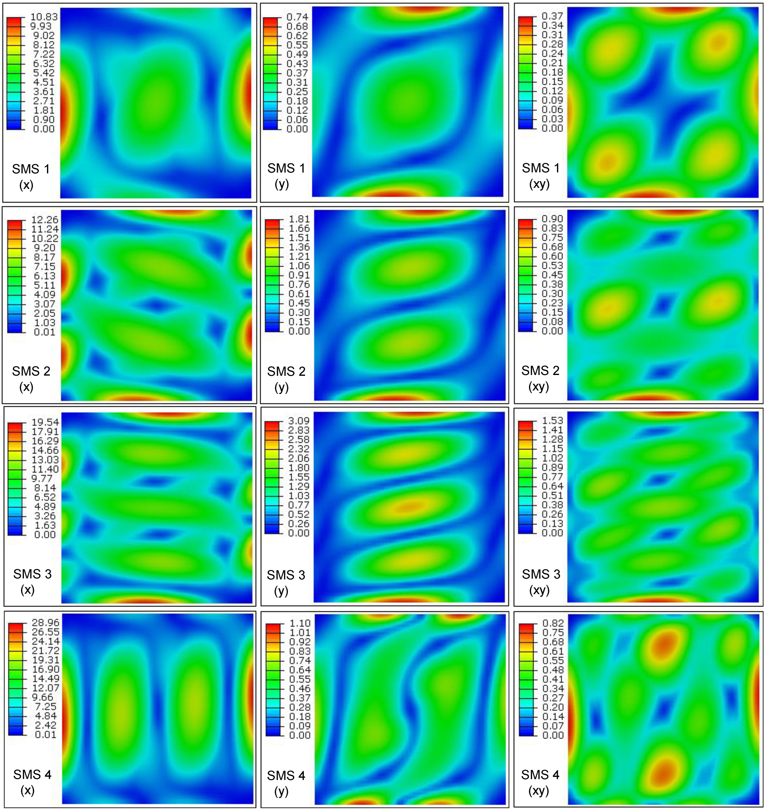
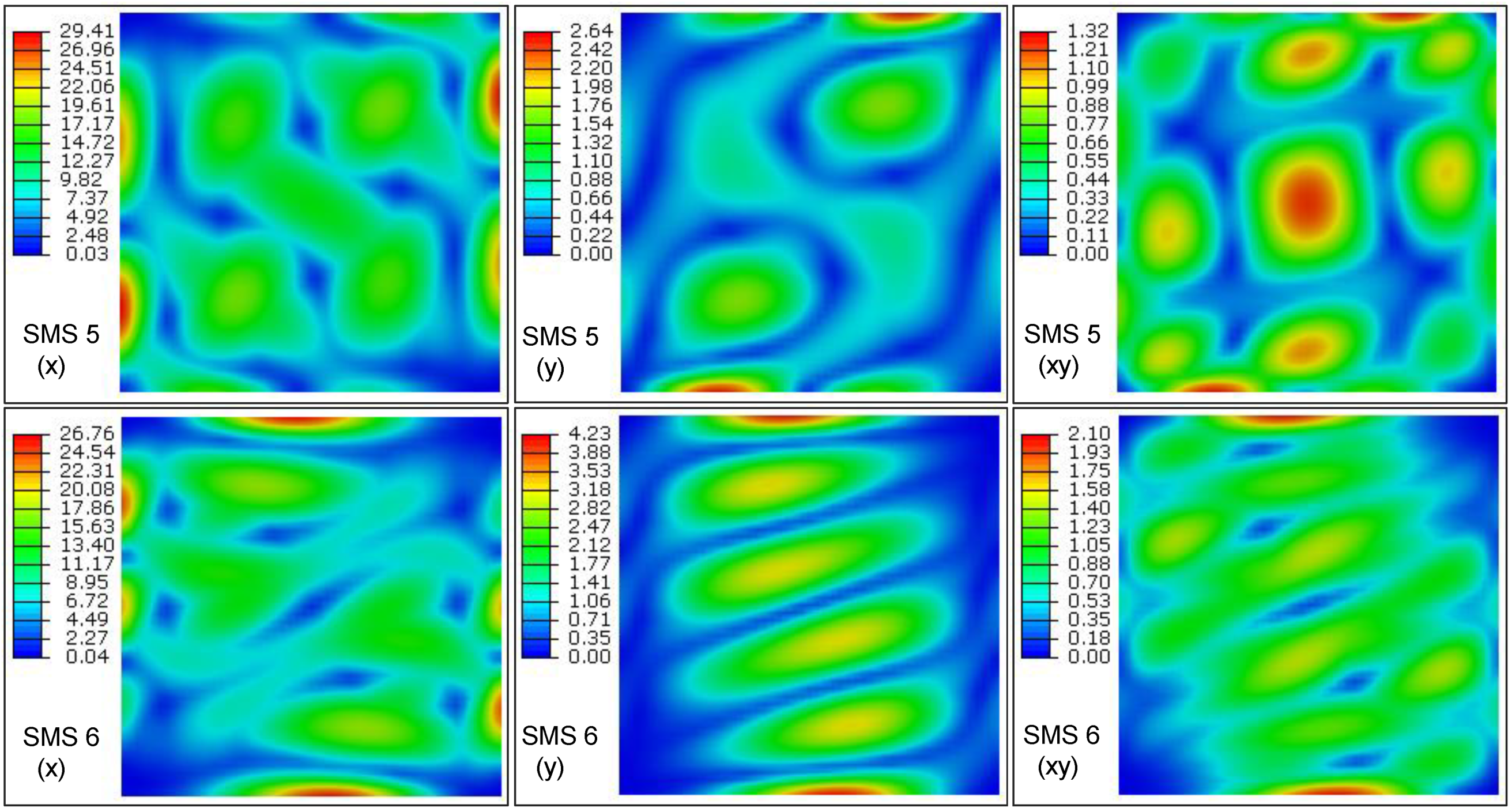
An envelope plot allows one to view a contour plot of the highest or lowest value of an output variable in FEM results for composite laminates. The criterion of the absolute maximum magnitude was chosen to find out the SMSs hotspots. From modal analysis, the first four envelope SMSs along the three in-plane stress directions are plotted in Figure 7. Firstly, it can be observed that relatively high values distribute along the clamped boundary edges, which are different from the DMSs of composite plates. Such law indicates that SMSs are useful for locating highly-stressed regions in composite laminates, which is similar with the case for metallic structures. Secondly, it can be seen that higher modes usually can give higher maximum values in SMSs. This distribution law will be vital for the vibroacoustic random fatigue of frequency-sensitive advanced composite laminates, where high-order local modes will result in high-frequency local dynamic stress, and hence contributes much more to the fatigue damage accumulation. From modal theory, higher modes generally contribute less to total dynamic response; however, the dynamic strength of some composite laminates greatly degrades with the increasing frequency [27]. High-frequency stress response will result in high peak factor, and hence the high threshold crossings [79]. Consequently, the vibration damage of composite laminates depends on the combined effect of the contributed vibration stress and material’s properties; while the first factor can be characterized by the SMSs. Furthermore, Figure 7 can indicate the two dimensions to observe the envelope SMSs: (1) the dimension of the mode order will be useful in determination of the relative modal contributions to the overall dynamic stress response; (2) the dimension of stress components can ensure the vector order of the SMSs agrees with that of the DMSs, so that matrix multiplication between the DMSs and the SMSs can be performed theoretically. Further, the relative magnitudes of different stress components can unravel the critical orientation for composite structural design. Two more SMSs are shown in Figure 8 for further comparison with the first four ones. Generally speaking, higher-order DMSs experience more complicated displacement fields and appear more local peak deflections. However, from the fifth and sixth envelope SMSs compared with the first four ones, there is no evidence to show that higher-order SMSs will appear more critical points for composite plates.
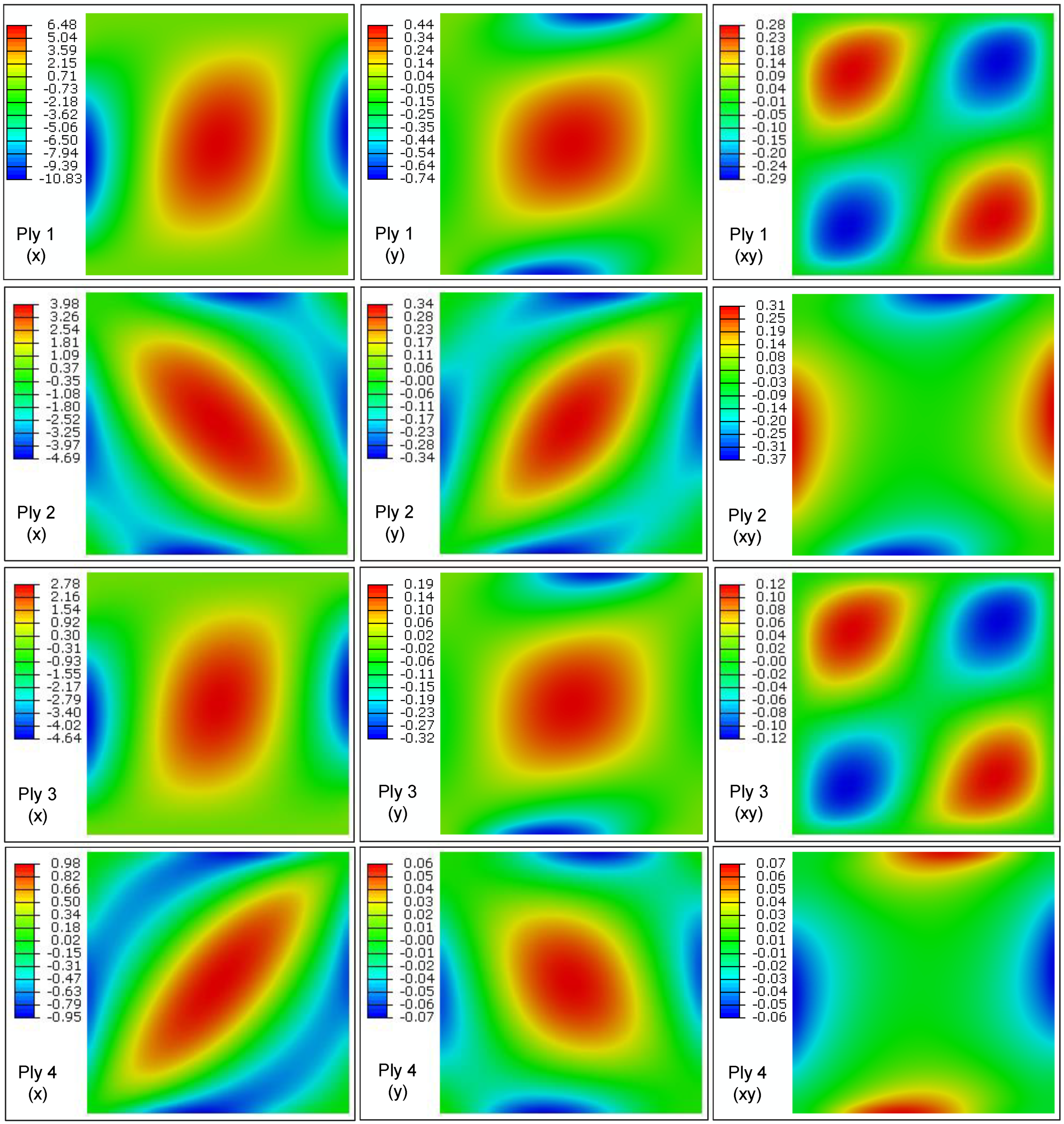
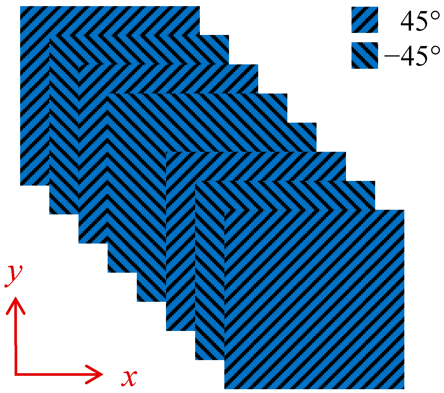
Contrary to the envelope SMSs, stress mode of each lamina can reveal the individual contribution of modal stress from the individual lamina, and hence design optimization can possibly be conducted with an emphasis on the laminas with high magnitude of modal stress. Observing the SMSs of 0° and ±45° plies shown in Figure 9, it can be comparatively found that SMSs in ±45° plies distribute more local peak points, while with lower peak values than these in 0° plies. For example, in the x-component stress mode at the first ply (0°), there are two highly-stressed regions, located at the middle of the two edges. Such distribution law also exhibits the consistency with the vibration fatigue analysis, where the failure location was at the mid-point of the outermost 0° layer [3]. However, the number of the highly-stressed regions in the stress mode is increased to five at the second ply (45°), with the peak magnitudes becoming more uniform. Considering these results, a designed plies can be proposed as Figure 10, in order to possibly achieve more uniformly-distributed SMSs, by means of using ±45° plies. Once the peak values of SMSs in individual laminas decrease, the envelope SMSs can be reduced. This fact provides a design criterion for ply angles, when envelope stresses are the primary concern, such as anti-failure analysis of composite structures under vibration loadings.
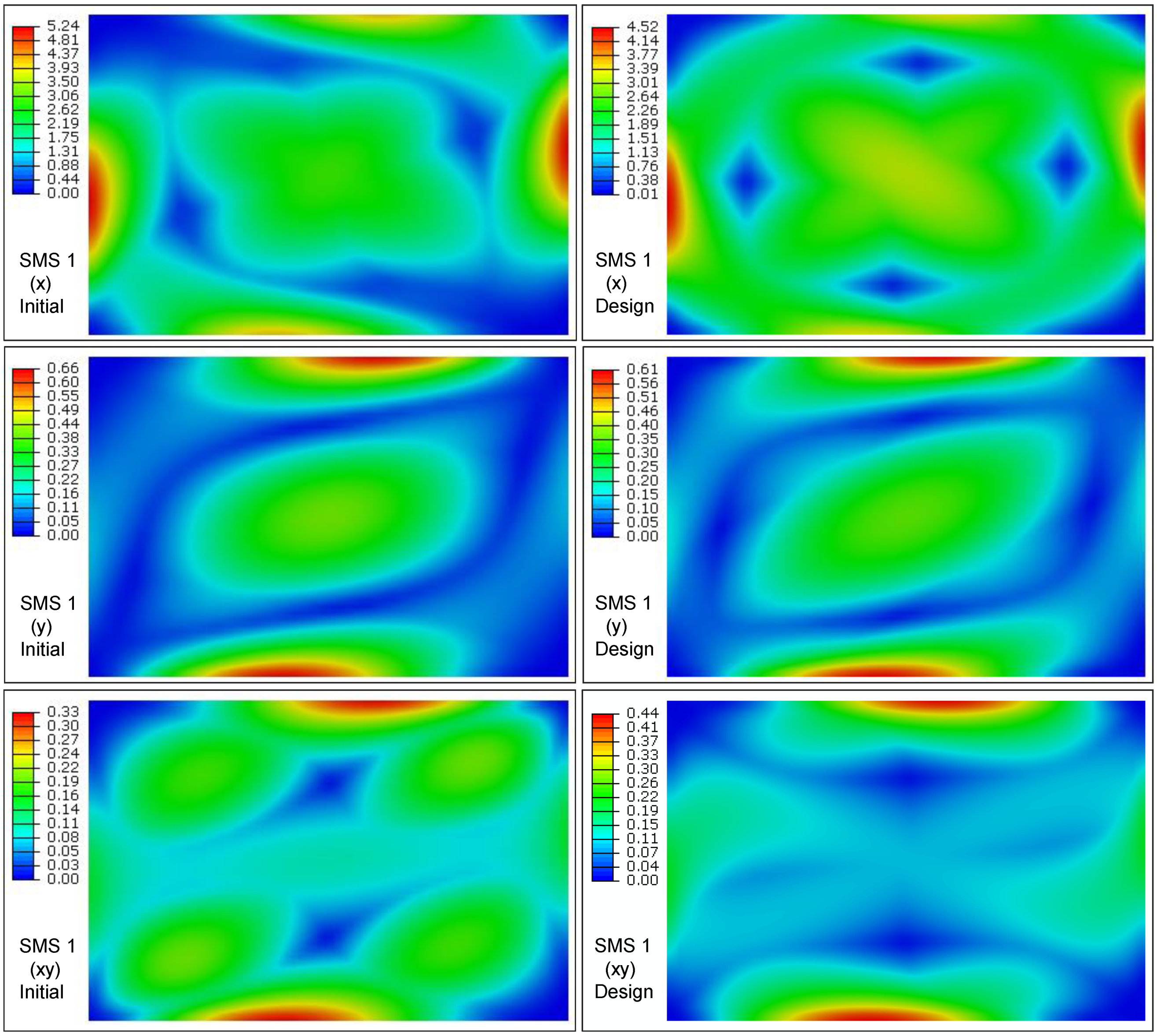
Figure 11 shows the first four envelope SMSs along three stress directions of the composite laminated plate with the designed layups. Comparing with the SMSs of initial composite laminated plate in Figure 7, it can be found that more peak points appear in the SMSs of all ±45°-ply laminate, while the peak values can by and large, achieve a decrease as given in Table 2. To highlight the different improvement degrees of the designed layup for the three components at each mode, the different background colours are used in the table with the deepest blue depicting the most optimal. These results can indicate the outperformance of the all ±45°-ply square laminated plate in terms of the dynamic stress reduction via the decreased and uniform modal stress distribution. However, ±45° design may possibly decrease the modal frequencies, which needs to be examined. Results of the first 11 frequencies are compared as Table 3, which indicates that the designed laminate exhibits higher modal frequencies on the whole, except the first and third modes. Results validate the fine dynamic properties of the designed laminated plies.
In summary, the results in present study can be condensed into the Figure 12, which exhibits three different dimensions to observe the SMSs of composite laminated thin plates. Three different dimensions of the stress modal matrix Φσ include (1) mode selection; (2) hotspot determination; and (3) critical ply. The first two are similar with the metallic structures, while the third one is the peculiar feature of composite laminated plates. In the graph, each grid represents one element in the modal matrix. For the anti-failure and crashworthiness design of aircraft composite structures, it is valuable to identify the critical hotspots in the critical layers at the predominant modes, so that the composite layup design with total structural weight unchanged can be effectively conducted by following the design criteria: (1) higher modal frequency; (2) lower and more uniform modal stress. The uniformly-distributed modal stress can ensure the structure more dynamically fully-stressed, so as to avoid the premature failure at local regions.
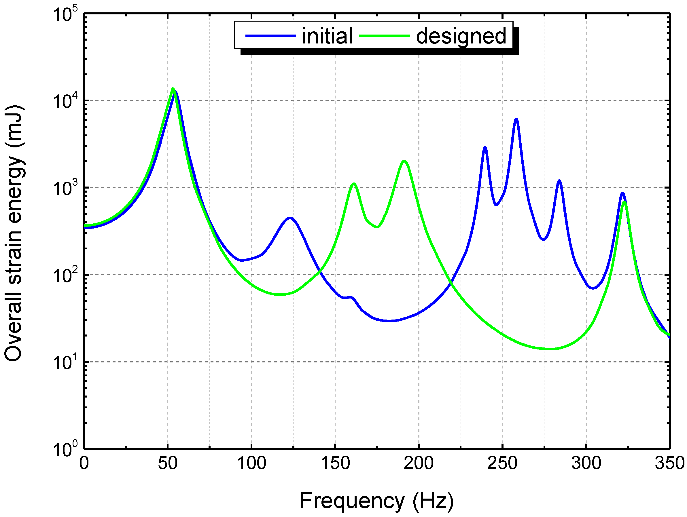
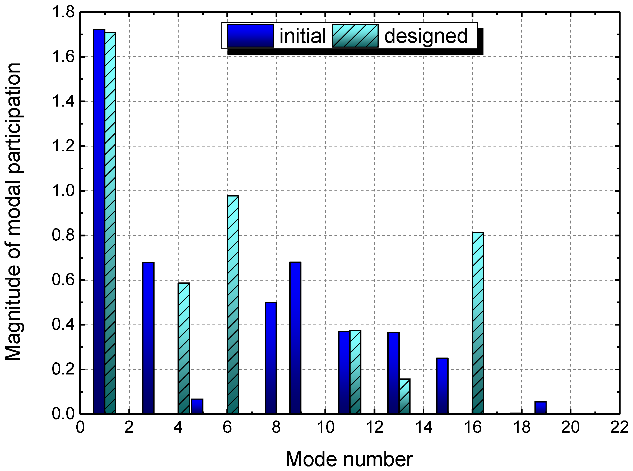
Furthermore, the frequency response analysis was conducted to evaluate the overall strain energy, which is a global metric to measure the stress and strain under forced vibration. Figure 13 plots the frequency-domain strain energies of the initial and designed square composite laminated plates, with the frequency range [0,350] Hz. Curves of the overall strain energy achieve peak values at the modal frequencies for both of the plates, which is similar with the other frequency response functions (FRFs). On the whole, the strain energy of the designed laminated plate was reduced, which verified the outperformance of the ±45° plies in dynamic stress reduction for the square plate. The reason of such result can be attributed to the reduction of the SMSs in nature. In addition, it can be seen that some of the peaks of strain energies appear at different mode numbers of the two square plates. This is mainly due to the variation in modal participations of the two composite plates, of which the values are compared as Figure 14. Magnitude of modal participation can assist to identify the predominant modes for dynamic stress response [68], which is an indicator for the modal vector dimension of composite laminated plates in Figure 12. In addition, from Figure 13 and Figure 14, it can be seen that both the modal participation factor and modal strain energy can be useful for mode selection. Such result agrees with the study by Esposito et al. [57], where the strain energy was used for mode selection of a composite wing box.
At last, the effect of aspect ratio on the layup design was considered. As an example, the rectangular laminated plate with aspect ratio of 3:2 was demonstrated. The in-plane size is 750 mm × 500 mm, and the initial layup was the same as that of the initial square plate. From the SMSs distributions of the initial rectangular plate, it can also be found that the 0° ply is highly stressed at the middle of the clamped edges. Considering the 3:2 aspect ratio and , therefore, the designed layup was selected as [30°/−30°/30°/−30°]s. Figure 15 compares the first envelope SMSs along the three directions of the rectangular laminated plates with the initial and designed layups. It can also be seen that the reduction in SMSs has achieved on the whole by using the designed layup.
Before the end, it is worthwhile to mention that present study only addressed the inherent modal properties of the composite laminated thin plates within the framework of classic laminate theory. It is obviously promising that stress modal analysis of composite laminates need to be investigated via the higher order theories [1], e.g., to include the shear deformation across the thickness direction and the delamination within the numerical framework. In addition, in the future work, the failure and crashworthiness analysis under dynamic loading need to be carried out and the role of stress modal analysis with the proper damage criteria of composite laminated structures should be verified.
5. Conclusions
A numerical investigation on stress modal analysis of composite laminates was conducted. Theoretical and numerical results indicate that the SMSs of composite laminates include two directions: (1) the in-plane directions, such as the x-, y-, xy-directions and the invariants, which is similar with the isotropic plate; and (2) the through thickness direction, i.e., the distribution in each layer or the envelope quantity. Therefore, the SMSs of composite laminate involve three different dimensions to interpret: (1) mode selection; (2) hotspot determination; and (3) critical ply. The first two are similar with the isotropic plates, while the third one is the peculiar feature of composite laminates. The SMSs of different plies will generally be different with each other, although they share the same deflections in DMSs. Such feature is different from the SMSs of isotropic materials, so as to reveal the critical hotspots in critical layers, which will be useful in dynamic failure analysis of composite structures. By observing the distributions of SMSs in different layers, ply angle design was performed to seek for the SMSs with more uniform distributions for both the square and the rectangular composite plates. The frequency-domain strain energy responses and modal participation factors of the composite laminated plates were evaluated. This process verifies the SMA of composite laminates can be a fast tool for dynamic stress reduction in structural design stage.
Lastly, it is worthwhile to mention that the SMSs of composite laminates need to be further investigated for assessment and design purpose of real composite structures with much more complex stacking sequence and geometric configurations; and that the higher order theory should be applied for more accurate results.
Author Contributions
Conceptualization, Y.Z.; Methodology, Y.Z.; Software, Y.Z.; Validation, Y.Z.; Formal Analysis, Y.Z.; Investigation, Y.Z.; Resources, Y.S. and W.Z.; Data Curation, Y.Z.; Writing—Original Draft Preparation, Y.Z.; Writing—Review and Editing, Y.Z.; Visualization, Y.Z.; Supervision, Y.Z.; Project Administration, Y.S. and W.Z.; Funding Acquisition, Y.S. and W.Z. All authors have read and agreed to the published version of the manuscript.
Funding
The authors acknowledge the financial support from the Joint Fund of National Natural Science Foundation of China and Civil Aviation Administration of China (U2033202, U1333119), the National Natural Science Foundation of China (62076126), and the National Science and Technology Major Project (2017-VIII-0003-0114, 2017-VIII-0002).
Institutional Review Board Statement
Not applicable.
Informed Consent Statement
Not applicable.
Data Availability Statement
Not applicable.
Acknowledgments
The authors are very grateful to the Editor and the three anonymous Reviewers whose insightful and constructive comments greatly helped us to improve the manuscript.
Conflicts of Interest
The authors declared no potential conflicts of interest with respect to the research, authorship, and/or publication of this article.
Nomenclature
| C | elastic matrix |
| D | damping matrix |
| f | exciting force vector |
| j | imaginary unit |
| K | stiffness matrix |
| M | mass matrix |
| H | displacement frequency response function |
| Hσ | stress frequency response function |
| S | compliance matrix |
| x | nodal displacement vector |
| w | out-of-plane deflection |
| ϕ | displacement mode shape |
| Φ | displacement modal matrix |
| ϕσ | stress mode shape |
| Φσ | stress modal matrix |
| ω | modal frequency |
| ε | strain vector |
| σ | stress vector |
| κ | modal curvature |
| FEM | finite element method |
| FRF | frequency response function |
| SFRF | stress frequency response function |
| SMA | stress modal analysis |
| SMSs | stress mode shapes |
References
- Reddy, J.N. Mechanics of Laminated Composite Plates and Shells; CRC Press: Boca Raton, FL, USA, 2003. [Google Scholar]
- Kessler, S.S.; Spearing, S.; Atalla, M.J.; Cesnik, C.E.; Soutis, C. Damage detection in composite materials using frequency response methods. Compos. Part B Eng. 2002, 33, 87–95. [Google Scholar] [CrossRef]
- Jayaprakash, K.; Muthukumar, M.; Desai, Y.M.; Naik, N.K. Vibration Induced Fatigue Analysis of [0n/90n]s Simply Supported Composite Plate Under Central Patch Impulse Loading. J. Eng. Mater. Technol. 2015, 137. [Google Scholar] [CrossRef]
- Zhou, S.; Sun, Y.; Guo, L. Random fatigue life prediction of carbon fibre-reinforced composite laminate based on hybrid time-frequency domain method. Adv. Compos. Mater. 2016, 26, 1–15. [Google Scholar] [CrossRef]
- Fan, Z.; Jiang, Y.; Zhang, S.; Chen, X. Experimental Research on Vibration Fatigue of CFRP and Its Influence Factors Based on Vibration Testing. Shock. Vib. 2017, 2017, 1–18. [Google Scholar] [CrossRef] [Green Version]
- Guida, M.; Marulo, F.; Abrate, S. Advances in crash dynamics for aircraft safety. Prog. Aerosp. Sci. 2018, 98, 106–123. [Google Scholar] [CrossRef]
- Zhao, W.; Kapania, R.K. Prestressed Vibration of Stiffened Variable-Angle Tow Laminated Plates. AIAA J. 2019, 57, 2575–2593. [Google Scholar] [CrossRef]
- Wu, Z.; Fang, G.; Fu, M.; Chen, X.; Liang, J.; Lv, D. Random fatigue damage accumulation analysis of composite thin-wall structures based on residual stiffness method. Compos. Struct. 2019, 211, 546–556. [Google Scholar] [CrossRef]
- Guida, M.; Sellitto, A.; Marulo, F.; Riccio, A. Analysis of the Impact Dynamics of Shape Memory Alloy Hybrid Composites for Advanced Applications. Materials 2019, 12, 153. [Google Scholar] [CrossRef] [Green Version]
- Riccio, A.; Saputo, S.; Sellitto, A.; Russo, A.; Di Caprio, F.; Di Palma, L. An Insight on the Crashworthiness Behavior of a Full-Scale Composite Fuselage Section at Different Impact Angles. Aerospace 2019, 6, 72. [Google Scholar] [CrossRef] [Green Version]
- Cawley, P.; Adams, R.D. A Vibration Technique for Non-Destructive Testing of Fibre Composite Structures. J. Compos. Mater. 1979, 13, 161–175. [Google Scholar] [CrossRef]
- Mondal, S.; Patra, A.; Chakraborty, S.; Mitra, N. Dynamic performance of sandwich composite plates with circular hole/cut-out: A mixed experimental–numerical study. Compos. Struct. 2015, 131, 479–489. [Google Scholar] [CrossRef]
- Murugan, R.; Ramesh, R.; Padmanabhan, K. Investigation on Mechanical Behaviour and Vibration Characteristics of Thin Walled Glass/Carbon Hybrid Composite Beams Under Fixed-Free Boundary Condition. Mech. Adv. Mater. Struct. 2016, 23, 909–916. [Google Scholar] [CrossRef]
- Sahoo, S.S.; Panda, S.K.; Sen, D. Effect of Delamination on Static and Dynamic Behavior of Laminated Composite Plate. AIAA J. 2016, 54, 2530–2544. [Google Scholar] [CrossRef]
- Mandal, A.; Ray, C.; Haldar, S. Free vibration analysis of laminated composite skew plates with cut-out. Arch. Appl. Mech. 2017, 87, 1511–1523. [Google Scholar] [CrossRef]
- Chaubey, A.K.; Kumar, A.; Chakrabarti, A. Vibration of Laminated Composite Shells with Cutouts and Concentrated Mass. AIAA J. 2018, 56, 1662–1678. [Google Scholar] [CrossRef]
- Yurddaskal, M.; Ozmen, U.; Kir, M.; Baba, B.O. The effect of foam properties on vibration response of curved sandwich composite panels. Compos. Struct. 2018, 183, 278–285. [Google Scholar] [CrossRef]
- Ewins, D.J. Modal Testing: Theory and Practice; Research Studies Press: Letchworth, UK, 1984. [Google Scholar]
- He, J.; Fu, Z.-F. Modal Analysis; Butterworth-Heinemann: Oxford, UK, 2001. [Google Scholar]
- Kranjc, T.; Slavič, J.; Boltežar, M. A comparison of strain and classic experimental modal analysis. J. Vib. Control. 2016, 22, 371–381. [Google Scholar] [CrossRef]
- Kim, S.; Cho, H.; Joo, H.; Shin, S.; Kwak, J. Equivalent Structural Modeling Using Laminated Composite Shell Analysis for the Nozzle Component of a Launch Vehicle Engine. J. Aerosp. Eng. 2018, 31, 04018078. [Google Scholar] [CrossRef]
- Zhao, W.; Gupta, A.; Regan, C.D.; Miglani, J.; Kapania, R.K.; Seiler, P.J. Component data assisted finite element model updating of composite flying-wing aircraft using multi-level optimization. Aerosp. Sci. Technol. 2019, 95, 105486. [Google Scholar] [CrossRef]
- Vo-Duy, T.; Ho-Huu, V.; Dang-Trung, H.; Nguyen-Thoi, T. A two-step approach for damage detection in laminated composite structures using modal strain energy method and an improved differential evolution algorithm. Compos. Struct. 2016, 147, 42–53. [Google Scholar] [CrossRef]
- Kim, Y.; Cho, H.; Park, S.; Kim, H.; Shin, S. Advanced Structural Analysis Based on Reduced-Order Modeling for Gas Turbine Blade. AIAA J. 2018, 56, 3369–3373. [Google Scholar] [CrossRef]
- Česnik, M.; Slavič, J.; Boltežar, M. Uninterrupted and accelerated vibrational fatigue testing with simultaneous monitoring of the natural frequency and damping. J. Sound Vib. 2012, 331, 5370–5382. [Google Scholar] [CrossRef]
- Anwar, W.; Khan, M.Z.; Israr, A.; Mehmood, S.; Anjum, N.A. Effect of structural dynamic characteristics on fatigue and damage tolerance of aerospace grade composite materials. Aerosp. Sci. Technol. 2017, 64, 39–51. [Google Scholar] [CrossRef]
- Zhou, Y.; Hang, X.; Wu, S.; Fei, Q.; Trisovic, N. Frequency-dependent random fatigue of panel-type structures made of ceramic matrix composites. Acta Mech. Solida Sin. 2017, 30, 165–173. [Google Scholar] [CrossRef]
- Boudjemai, A.; Amri, R.; Mankour, A.; Salem, H.; Bouanane, M.; Boutchicha, D. Modal analysis and testing of hexagonal honeycomb plates used for satellite structural design. Mater. Des. 2012, 35, 266–275. [Google Scholar] [CrossRef]
- Fan, W.; Qiao, P. Vibration-based damage identification methods: A review and comparative study. Struct. Health Monit. 2011, 10, 83–111. [Google Scholar] [CrossRef]
- Rucevskis, S.; Janeliukstis, R.; Akishin, P.; Chate, A. Mode shape-based damage detection in plate structure without baseline data. Struct. Control Health Monit. 2016, 23, 1180–1193. [Google Scholar] [CrossRef]
- Cao, S.; Ouyang, H.; Cheng, L. Baseline-free adaptive damage localization of plate-type structures by using robust PCA and Gaussian smoothing. Mech. Syst. Signal Process. 2019, 122, 232–246. [Google Scholar] [CrossRef]
- Yam, L.Y.; Leung, T.P.; Li, D.B.; Xue, K.Z. Theoretical and experimental study of modal strain analysis. J. Sound Vib. 1996, 191, 251–260. [Google Scholar] [CrossRef]
- Li, Y.Y.; Cheng, L.; Yam, L.H.; Wong, W.O. Identification of damage locations for plate-like structures using damage sensitive indices: Strain modal approach. Comput. Struct. 2002, 80, 1881–1894. [Google Scholar] [CrossRef]
- Lee, E.-T.; Rahmatalla, S.; Eun, H.-C. Damage detection by mixed measurements using accelerometers and strain gages. Smart Mater. Struct. 2013, 22, 075014. [Google Scholar] [CrossRef]
- Shadan, F.; Khoshnoudian, F.; Esfandiari, A. Structural Damage Identification Based on Strain Frequency Response Functions. Int. J. Struct. Stab. Dyn. 2018, 18, 1850159. [Google Scholar] [CrossRef]
- Su, W.; Cesnik, C.E.S. Strain-Based Analysis for Geometrically Nonlinear Beams: A Modal Approach. J. Aircr. 2014, 51, 890–903. [Google Scholar] [CrossRef] [Green Version]
- Skafte, A.; Aenlle, M.L.; Brincker, R. A general procedure for estimating dynamic displacements using strain measurements and operational modal analysis. Smart Mater. Struct. 2016, 25, 025020. [Google Scholar] [CrossRef]
- Wang, Z.-C.; Geng, D.; Ren, W.-X.; Liu, H.-T. Strain modes based dynamic displacement estimation of beam structures with strain sensors. Smart Mater. Struct. 2014, 23, 125045. [Google Scholar] [CrossRef]
- Česnik, M.; Slavič, J.; Čermelj, P.; Boltežar, M. Frequency-based structural modification for the case of base excitation. J. Sound Vib. 2013, 332, 5029–5039. [Google Scholar] [CrossRef]
- Xie, C.; Xue, P. An accurate and efficient computational method for structural dynamic stresses under random loading. Aerosp. Sci. Technol. 2016, 59, 11–17. [Google Scholar] [CrossRef]
- Braccesi, C.; Cianetti, F.; Tomassini, L. Fast evaluation of stress state spectral moments. Int. J. Mech. Sci. 2017, 127, 4–9. [Google Scholar] [CrossRef]
- Braccesi, C.; Cianetti, F.; Tomassini, L. An innovative modal approach for frequency domain stress recovery and fatigue damage evaluation. Int. J. Fatigue 2016, 91, 382–396. [Google Scholar] [CrossRef]
- Mršnik, M.; Slavič, J.; Boltežar, M. Vibration fatigue using modal decomposition. Mech. Syst. Signal Process. 2018, 98, 548–556. [Google Scholar] [CrossRef]
- Li, F.; Wu, H.; Wu, P. Vibration fatigue dynamic stress simulation under non-stationary state. Mech. Syst. Signal Process. 2021, 146, 107006. [Google Scholar] [CrossRef]
- Zhou, Y.; Fei, Q.; Wu, S. Utilization of modal stress approach in random-vibration fatigue evaluation. In Proceedings of the Institution of Mechanical Engineers, Part G. J. Aerosp. Eng. 2017, 213, 2603–2615. [Google Scholar]
- Zhou, Y.; Tao, J. Theoretical and numerical investigation of stress mode shapes in multi-axial random fatigue. Mech. Syst. Signal Process. 2019, 127, 499–512. [Google Scholar] [CrossRef]
- Zhou, Y. Local Finite Element Refinement for Accurate Dynamic Stress via Modal Information Only. AIAA J. 2020, 58, 3593–3606. [Google Scholar] [CrossRef]
- Lestari, W.; Qiao, P.; Hanagud, S. Curvature Mode Shape-based Damage Assessment of Carbon/Epoxy Composite Beams. J. Intell. Mater. Syst. Struct. 2006, 18, 189–208. [Google Scholar] [CrossRef]
- Qiao, P.; Lu, K.; Lestari, W.; Wang, J. Curvature mode shape-based damage detection in composite laminated plates. Compos. Struct. 2007, 80, 409–428. [Google Scholar] [CrossRef]
- Frieden, J.; Cugnoni, J.; Botsis, J.; Gmür, T.; Coric, D. High-speed internal strain measurements in composite structures under dynamic load using embedded FBG sensors. Compos. Struct. 2010, 92, 1905–1912. [Google Scholar] [CrossRef]
- Shariyat, M.; Alipour, M.M. Differential transform vibration and modal stress analyses of circular plates made of two-directional functionally graded materials resting on elastic foundations. Arch. Appl. Mech. 2010, 81, 1289–1306. [Google Scholar] [CrossRef]
- Dos Santos, F.L.M.; Peeters, B.; Lau, J.; Desmet, W.; Góes, L.C.S. The use of strain gauges in vibration-based damage detection. J. Phys. Conf. Ser. 2015, 628, 012119. [Google Scholar] [CrossRef] [Green Version]
- Yang, Z.-B.; Radzieński, M.; Kudela, P.; Ostachowicz, W. Two-dimensional modal curvature estimation via Fourier spectral method for damage detection. Compos. Struct. 2016, 148, 155–167. [Google Scholar] [CrossRef]
- Ooijevaar, T.H.; Warnet, L.L.; Loendersloot, R.; Akkerman, R.; Tinga, T. Impact damage identification in composite skin-stiffener structures based on modal curvatures. Struct. Control Health Monit. 2015, 23, 198–217. [Google Scholar] [CrossRef]
- Loutas, T.; Bourikas, A. Strain sensors optimal placement for vibration-based structural health monitoring. The effect of damage on the initially optimal configuration. J. Sound Vib. 2017, 410, 217–230. [Google Scholar] [CrossRef]
- Zhen, W.; Wanji, C. Free and Forced Vibration of Laminated Composite Beams. AIAA J. 2018, 56, 2877–2886. [Google Scholar] [CrossRef]
- Esposito, M.; Gherlone, M. Composite wing box deformed-shape reconstruction based on measured strains: Optimization and comparison of existing approaches. Aerosp. Sci. Technol. 2020, 99, 105758. [Google Scholar] [CrossRef]
- Müzel, S.D.; Bonhin, E.P.; Guimarães, N.M.; Guidi, E.S. Application of the Finite Element Method in the Analysis of Composite Materials: A Review. Polymers 2020, 12, 818. [Google Scholar] [CrossRef] [PubMed] [Green Version]
- Rezaiee-Pajand, M.; Arabi, E.; Masoodi, A.R. Nonlinear analysis of FG-sandwich plates and shells. Aerosp. Sci. Technol. 2019, 87, 178–189. [Google Scholar] [CrossRef]
- Rezaiee-Pajand, M.; Masoodi, A.R. Hygro-thermo-elastic nonlinear analysis of functionally graded porous composite thin and moderately thick shallow panels. Mech. Adv. Mater. Struct. 2020, 1–19. [Google Scholar] [CrossRef]
- Srinivas, S. A refined analysis of composite laminates. J. Sound Vib. 1973, 30, 495–507. [Google Scholar] [CrossRef]
- Messina, A. Three-Dimensional Free Vibration Analysis of Cross-Ply Laminated Rectangular Plates through 2D and Exact Models. Mech. Adv. Mater. Struct. 2012, 19, 250–264. [Google Scholar] [CrossRef]
- Grover, N.; Singh, B.; Maiti, D. Analytical and finite element modeling of laminated composite and sandwich plates: An assessment of a new shear deformation theory for free vibration response. Int. J. Mech. Sci. 2013, 67, 89–99. [Google Scholar] [CrossRef]
- Sayyad, A.S.; Ghugal, Y.M. On the free vibration analysis of laminated composite and sandwich plates: A review of recent literature with some numerical results. Compos. Struct. 2015, 129, 177–201. [Google Scholar] [CrossRef]
- Sayyad, A.S.; Ghugal, Y.M. On the free vibration of angle-ply laminated composite and soft core sandwich plates. J. Sandw. Struct. Mater. 2017, 19, 679–711. [Google Scholar] [CrossRef]
- Vidal, P.; Gallimard, L.; Polit, O. Free vibration analysis of composite plates based on a variable separation method. Compos. Struct. 2019, 230, 111493. [Google Scholar] [CrossRef] [Green Version]
- Tiwari, P.; Barman, S.K.; Maiti, D.K.; Maity, D. Free Vibration Analysis of Delaminated Composite Plate Using 3D Degenerated Element. J. Aerosp. Eng. 2019, 32, 04019070. [Google Scholar] [CrossRef]
- Almitani, K.H.; Abdelrahman, A.A.; Eltaher, M.A. Influence of the perforation configuration on dynamic behaviors of multilayered beam structure. Structures 2020, 28, 1413–1426. [Google Scholar] [CrossRef]
- Li, D.; Wang, Z.; Zhang, C. A multi-level and multi-site mesh refinement method for the 2D problems with microstructures. Mech. Adv. Mater. Struct. 2019, 1–18. [Google Scholar] [CrossRef]
- Melo, J.D.D.; Bi, J.; Tsai, S.W. A novel invariant-based design approach to carbon fiber reinforced laminates. Compos. Struct. 2017, 159, 44–52. [Google Scholar] [CrossRef] [Green Version]
- Carrera, E.; Fiordilino, G.; Nagaraj, M.; Pagani, A.; Montemurro, M. A global/local approach based on CUF for the accurate and efficient analysis of metallic and composite structures. Eng. Struct. 2019, 188, 188–201. [Google Scholar] [CrossRef]
- Benasciutti, D.; Tovo, R. Frequency-based analysis of random fatigue loads: Models, hypotheses, reality. Mater. Werkst. 2018, 49, 345–367. [Google Scholar] [CrossRef]
- Cornwell, P.; Doebling, S.; Farrar, C. Application of the strain energy damage detection method to plate-like structures. J. Sound Vib. 1999, 224, 359–374. [Google Scholar] [CrossRef]
- Fan, W.; Qiao, P. A strain energy-based damage severity correction factor method for damage identification in plate-type structures. Mech. Syst. Signal Process. 2012, 28, 660–678. [Google Scholar] [CrossRef]
- Xu, W.; Cao, M.; Ostachowicz, W.; Radzieński, M.; Xia, N. Two-dimensional curvature mode shape method based on wavelets and Teager energy for damage detection in plates. J. Sound Vib. 2015, 347, 266–278. [Google Scholar] [CrossRef]
- Hu, H.; Wang, B.-T.; Lee, C.-H.; Su, J.-S. Damage detection of surface cracks in composite laminates using modal analysis and strain energy method. Compos. Struct. 2006, 74, 399–405. [Google Scholar] [CrossRef]
- Zhou, Y.; Sun, Y.; Huang, T. SPH-FEM Design of Laminated Plies under Bird-Strike Impact. Aerospace 2019, 6, 112. [Google Scholar] [CrossRef] [Green Version]
- Wijker, J.J. Random Vibrations in Spacecraft Structures Design: Theory and Applications; Gladwell, G.M.L., Ed.; Springer: London, UK, 2009. [Google Scholar]
- Preumont, A. Twelve Lectures on Structural Dynamics; Gladwell, G.M.L., Ed.; Springer: London, UK, 2013. [Google Scholar]
Figure 1.
Flowchart for stress modal analysis of composite laminated plates in present study.

Figure 2.
Schematic representation of rectangular angle-ply laminated plate and the coordinate systems.
Figure 2.
Schematic representation of rectangular angle-ply laminated plate and the coordinate systems.

Figure 3.
Ply angles of the initially considered composite laminated plate.

Figure 4.
Three different FEM meshes of the square laminated thin plate: (a) coarse mesh with 25 × 25 elements; (b) moderate mesh with 50 × 50 elements; (c) dense mesh with 100 × 100 elements.
Figure 4.
Three different FEM meshes of the square laminated thin plate: (a) coarse mesh with 25 × 25 elements; (b) moderate mesh with 50 × 50 elements; (c) dense mesh with 100 × 100 elements.

Figure 5.
Modal frequencies of the square laminated thin plate via three different FEM meshes.

Figure 6.
The first six DMSs of the initial composite laminated plate (DMS: Displacement mode shape).
Figure 6.
The first six DMSs of the initial composite laminated plate (DMS: Displacement mode shape).

Figure 7.
The first four envelope SMSs along three stress directions of the initial composite laminated plate (SMS: Stress mode shape).
Figure 7.
The first four envelope SMSs along three stress directions of the initial composite laminated plate (SMS: Stress mode shape).

Figure 8.
The fifth and sixth envelope SMSs along three stress directions of the initial composite laminated plate (SMS: Stress mode shape).
Figure 8.
The fifth and sixth envelope SMSs along three stress directions of the initial composite laminated plate (SMS: Stress mode shape).

Figure 9.
The first SMSs along three stress directions at different plies of the initial composite laminated plate: (Ply 1) outmost 0° ply; (Ply 2) 45° ply; (Ply 3) inner 0° ply; (Ply 4) −45° ply.
Figure 9.
The first SMSs along three stress directions at different plies of the initial composite laminated plate: (Ply 1) outmost 0° ply; (Ply 2) 45° ply; (Ply 3) inner 0° ply; (Ply 4) −45° ply.

Figure 10.
Designed plies of the square laminated plate for SMSs reduction.

Figure 11.
The first four envelope SMSs along three stress directions of the composite laminated plate with the designed layups (SMS: stress mode shape).
Figure 11.
The first four envelope SMSs along three stress directions of the composite laminated plate with the designed layups (SMS: stress mode shape).

Figure 12.
Three different dimensions to observe the SMSs of composite laminated plates in present study.
Figure 12.
Three different dimensions to observe the SMSs of composite laminated plates in present study.

Figure 13.
Frequency-domain strain energies of the initial and designed square composite laminated plates.
Figure 13.
Frequency-domain strain energies of the initial and designed square composite laminated plates.

Figure 14.
Modal participations of the two square composite laminated plates.

Figure 15.
The first envelope SMSs along the three directions of the rectangular laminated plates with the initial and designed layups.
Figure 15.
The first envelope SMSs along the three directions of the rectangular laminated plates with the initial and designed layups.


Table 1.
Mechanical and geometric properties of CFRP lamina of the square plate [77].
Table 1.
Mechanical and geometric properties of CFRP lamina of the square plate [77].
| Property/Notation | Value |
|---|---|
| Longitudinal modulus E11 (GPa) | 181 |
| Transverse modulus E22 (GPa) | 10.3 |
| Shear modulus G12 (GPa) | 7.17 |
| Poisson’s ratio ν12 | 0.28 |
| Mass density ρ (kg/m3) | 1600 |
| Length a = b (mm) | 500 |
| Thickness h (mm) | 1.2 |
Table 2.
The maximum magnitudes of the first six envelope SMSs along the three directions.
| Mode Number | Maximum Magnitude of the Stress Mode | |||||
|---|---|---|---|---|---|---|
| Initial Layup | Designed Layup | |||||
| x | y | xy | x | y | xy | |
| 1 | 10.83 | 0.74 | 0.37 | 6.74 | 0.49 | 0.53 |
| 2 | 12.26 | 1.82 | 0.90 | 13.73 | 1.10 | 1.08 |
| 3 | 19.54 | 3.09 | 1.53 | 15.00 | 1.09 | 1.18 |
| 4 | 28.96 | 1.10 | 0.82 | 20.83 | 1.63 | 1.64 |
| 5 | 29.41 | 2.64 | 1.32 | 26.61 | 1.94 | 2.10 |
| 6 | 26.76 | 4.24 | 2.11 | 29.86 | 1.83 | 1.98 |
Table 3.
Comparison of the first 11 modal frequencies.
| Mode Number | Modal Frequency (Hz) | ||
|---|---|---|---|
| Initial Layup | Designed Layup | Percent of Change (%) | |
| 1 | 54.4 | 52.9 | −2.7 |
| 2 | 80.2 | 101.4 | 26.5 |
| 3 | 123.8 | 111.2 | −10.2 |
| 4 | 135.6 | 161.2 | 18.9 |
| 5 | 160.1 | 183.5 | 14.6 |
| 6 | 179.0 | 191.5 | 7.0 |
| 7 | 208.4 | 235.1 | 12.8 |
| 8 | 239.6 | 259.6 | 8.4 |
| 9 | 258.2 | 289.5 | 12.1 |
| 10 | 280.1 | 295.6 | 5.5 |
| 11 | 284.0 | 322.8 | 13.7 |
Publisher’s Note: MDPI stays neutral with regard to jurisdictional claims in published maps and institutional affiliations. |
© 2021 by the authors. Licensee MDPI, Basel, Switzerland. This article is an open access article distributed under the terms and conditions of the Creative Commons Attribution (CC BY) license (http://creativecommons.org/licenses/by/4.0/).
Share and Cite
MDPI and ACS Style
Zhou, Y.; Sun, Y.; Zeng, W. A Numerical Investigation on Stress Modal Analysis of Composite Laminated Thin Plates. Aerospace 2021, 8, 63. https://0-doi-org.brum.beds.ac.uk/10.3390/aerospace8030063
AMA Style
Zhou Y, Sun Y, Zeng W. A Numerical Investigation on Stress Modal Analysis of Composite Laminated Thin Plates. Aerospace. 2021; 8(3):63. https://0-doi-org.brum.beds.ac.uk/10.3390/aerospace8030063
Chicago/Turabian StyleZhou, Yadong, Youchao Sun, and Weili Zeng. 2021. "A Numerical Investigation on Stress Modal Analysis of Composite Laminated Thin Plates" Aerospace 8, no. 3: 63. https://0-doi-org.brum.beds.ac.uk/10.3390/aerospace8030063
Note that from the first issue of 2016, this journal uses article numbers instead of page numbers. See further details here.