
A Separation and Desalination Process for Farmland Saline-Alkaline Water
by
 , ,
, ,
Qiaonan Yang
1,2 ,
,
Can Hu
1,2,
Jie Li
1,2,
Xiaokang Yi
1,2,*,
Yichuan He
1,2,
Jie Zhang
1,2 and
Zhilin Sun
3 1
College of Mechanical and Electrical Engineering, Tarim University, Alar 843300, China
2
Agricultural Engineering Key Laboratory, Universities of Education Department of Xinjiang Uygur Autonomous Region, Tarim University, Alar 843300, China
3
Ocean College, Zhejiang University, Hangzhou 310058, China
*
Author to whom correspondence should be addressed.
Agriculture 2021, 11(10), 1001; https://0-doi-org.brum.beds.ac.uk/10.3390/agriculture11101001
Submission received: 26 August 2021
/
Revised: 8 October 2021
/
Accepted: 9 October 2021
/
Published: 13 October 2021
(This article belongs to the Special Issue Management and Strategies for Improving the Use of Saline Water in Agriculture)
Abstract
:Salination poses serious hazards to farmland soil. For the purpose of solving soil salination, desalination of water sources, and other problems faced by arid areas, a separation and desalination process for farmland saline-alkaline water is proposed; a separation and desalination device based on this process is also presented and tested. Results indicate that water associated with the pretreatment device satisfied the working conditions of the composite nanofiltration (NF)-reverse osmosis (RO) membrane system. The composite NF-RO membrane system produced a better filtering effect than either the NF membrane or the RO membrane. When used for filtering saline-alkaline water, the composite NF-RO membrane system achieved a desalination rate of 96.06%, a total hardness removal rate of 98.93%, and a Cl- removal rate of 99.32%, adhering to the standard for irrigation water quality. The flashing-condensation process realized a fresh water recovery rate greater than 70%. During brine evaporation using solar salt making processes, the primary compound of crystals precipitated was NaCl (with a relative content of 93%), suggesting that the precipitates have the potential values of industrial salts. These findings offer new technical references for solving the problem of farmland irrigation water faced by saline-alkaline areas worldwide.
1. Introduction
Salination not only poses serious hazards to farmland soil, it also has a significant effect on crop growth environments and groundwater resources [1,2]. Saline-alkaline land formed as a result of salination has attracted global attention [3,4]. According to reports [5,6], the total global scale of saline-alkaline farmlands has reached about 800 million ha., accounting for 6% of the total area of the world’s arable land. In China, issues related to soil salination are mainly concentrated in the northwestern area. For example, soil salination in the Xinjiang Uygur Autonomous Region (hereinafter referred to as “Xinjiang”) accounts for 22.01% of the total area of China’s saline-alkaline lands [7]. Xinjiang is also the largest province in China [8], having the highest soil salinity and the most important agricultural production base. In order to increase grain yield in this province, a series of measures for the active governance of soil salination have been undertaken. The most widely adopted measure is salt leaching [9,10]. Here, saline-alkaline lands are irrigated to dissolve soil salts, discharging soluble salts from topsoil into deep soil (or leaching them out) through infiltration [11]. In this manner, harmful salt contents in the soil are reduced through lateral seepage into drainage canals, thus making the soil arable [12]. However, this measure may make it difficult to desalinate saline-alkaline water discharged after salt leaching. Currently, salts are mainly discharged via farmland alkali drainage canals into rivers and agricultural areas, thereby incurring more salination pollution and resulting in more serious issues [13,14]. In this context, the key to preventing and governing source salination pollution is to efficiently and effectively separate and desalinate agricultural saline-alkaline water discharged after salt leaching.
Regarding separation and desalination of saline-alkaline water, there is an urgent need for a technique that can be employed to separate and desalinate agricultural saline-alkaline water. To date, there has been a lack of research on separation and desalination techniques for farmland saline-alkaline water, with investigations in this field mainly focusing on seawater desalination techniques, such as solar-driven seawater desalination [15,16], multistage flash (MSF) [17,18], humidification-dehumidification (HDH) [19,20], and membrane filtration [21,22,23]. In 2014, Mamouri et al. [24] explored the effects of heat-collecting temperature, solar irradiation intensity, and other factors on the performance of a collector tube by developing a saline water desalination device consisting of a solar collector tube and a brine evaporator, with an inclination of 35 °C. In 2015, Mosleh et al. [25] added a trough reflector on the collector tube to increase its absorption rate. In 2019, Sun et al. [26] performed a two-phase flow test on a circulating solar collector tube at the Zijingang Campus of Zhejiang University, and assembled the collector tube by means of horizontal series connections to simulate the heat-collecting efficiency of the collector tube at different flow velocities. Lacroix et al. [27] introduced a new type of thermal power reverse osmosis desalination process. This new thermal hydraulic process used solar energy to pressurize sea water and made it exceed osmotic pressure, to desalinate it. In 2020, Toth [28] simulated the desalination process of multistage flash (MSF) + reverse osmosis (RO), evaluating the wastewater desalination effect of this process under stable conditions. In summary, there is currently a lack of mature technological processes for desalinating farmland saline-alkaline water (high-salinity surface water) into industrial, agricultural, or primary pure water suitable for human consumption. In 2021, Wang et al. [29] adopted the methods of solar power supply and RO membrane filtration, designed and analyzed the energy consumption of a small RO seawater desalination device, and determined that the optimal recovery rate of the device was 20–30%. Tian et al. [30] used nanofiltration (NF) technology to treat brackish water, and finally the concentrated water from the experimental device was discharged directly without treatment. Considering that existing seawater desalination methods are largely unavailable for the desalination of farmland saline-alkaline water, efficient and effective separation and desalination should be developed to separate and desalinate farmland saline-alkaline water discharged after salt leaching, thereby reducing pollution associated with this process.
Separation and desalination of farmland saline-alkaline water was examined in this study by collecting saline-alkaline water discharged after salt leaching of farmlands in Alar City, Xinjiang. A separation and desalination technique for farmland saline-alkaline water was also proposed. The main contents of this study include: (1) A technological process for the separation and desalination for farmland saline-alkaline water was proposed. (2) A composite NF- RO membrane system was prepared by combining the NF membrane and the RO membrane, and used for filtering saline-alkaline water. The composite NF-RO membrane system was compared with the NF membrane and the RO membrane in terms of its desalination effect, total hardness removal rate, and Cl- removal rate. (3) An experimental separation and desalination device was designed for farmland saline-alkaline water based on the separation and desalination process. The process of solar salt making through brine evaporation, and the separation and desalination effect of the composite NF-RO membrane system, were experimentally validated. This study offers new technical references for solving the problem of farmland irrigation water faced by saline-alkaline areas worldwide.
2. Design of the Separation and Desalination Process for Farmland Saline-Alkaline Water
2.1. Separation and Desalination Process Used for Farmland Saline-Alkaline Water
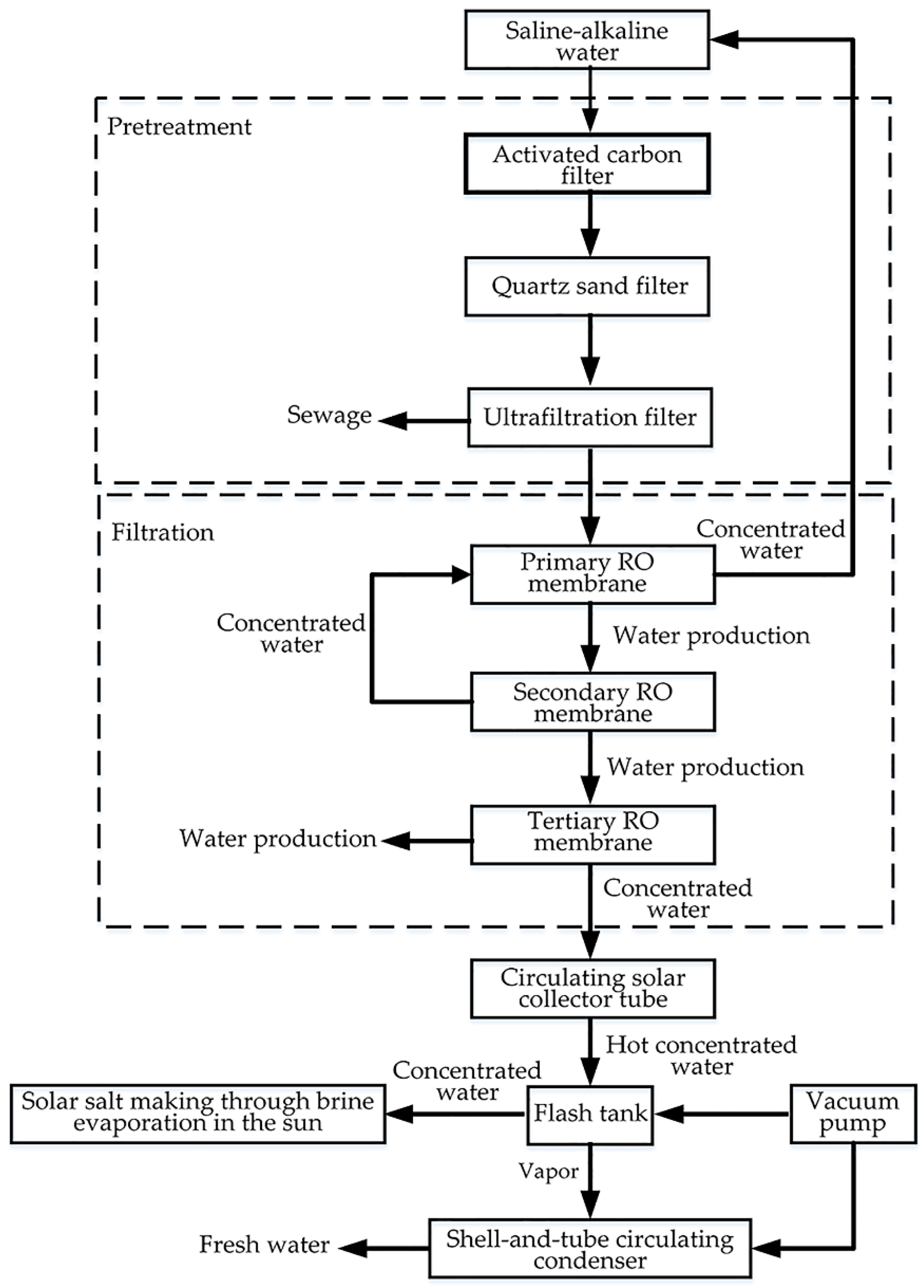
By combining the composite NF-RO membrane system and the circulating solar collector tube based on the heating-flashing-condensation method, we defined the separation and desalination process flow for farmland saline-alkaline water. The steps used in this method are shown in Figure 1.
- Step 1: Sample pretreatment. Because the sampled saline-alkaline water had poor quality and could not be directly filtered by the composite NF-RO membrane system, pretreatment was initially undertaken. Pre-treated saline-alkaline water for analysis was obtained by pumping collected saline-alkaline water in succession into a self-developed quartz sand filter, an activated carbon filter, and an ultrafiltration filter.
- Step 2: Separation and desalination through NF-RO. The pre-treated saline-alkaline water was fed into the primary and secondary RO membranes and the tertiary NF membrane. The saline-alkaline water was pumped using the primary RO pump into the primary RO membrane for filtration, while concentrated water flowed back to the original water tank for repeated filtration. Water was then pumped by the secondary RO pump into the secondary RO membrane for filtration, while secondary concentrated water was pumped by the primary RO pump into the primary RO membrane for repeated filtration. The water yielded was pumped by the tertiary NF pump into the tertiary NF membrane for filtration, after which the filtered water was used for farmland irrigation. The tertiary concentrated water then entered the circulating solar collector tube.
- Step 3: Heating treatment in the circulating solar collector tube. After being filtered by the composite NF-RO membrane system, tertiary concentrated water entered the circulating solar collector tube. Under solar irradiation, tertiary concentrated water entering the circulating solar collector tube absorbed thermal energy from the tube wall, resulting in continuous heating.
- Step 4: Flash distillation. After being heated in the circulating solar collector tube, tertiary concentrated water entered the flash tank for distillation via its internal atomizing nozzle, and it was further concentrated under the action of a vacuum pump. In the evaporation process, one portion of the concentrated water turned into vapor, which entered the inlet of the shell-and-tube circulating condenser via the air vent at the top of the flash tank. The rest of the concentrated water formed the concentrate. When the concentrate in the flash tank reached the critical salinity, the water-ring vacuum pump and the inlet valve were shut off, and the concentrate was drained via the bottom salt outlet of the flash tank into the solar salt box for solar salt making via brine evaporation.
- Step 5: Condensation by the shell-and-tube circulating condenser. Vapor in the flash tank entered the shell-and-tube circulating condenser via its left inlet, while fresh water was discharged via the right outlet. Under the action of the water pump, cooling water flowed into the shell-and-tube circulating condenser from the bottom, flowing out from the top.
2.2. Implementation of the Separation and Desalination Process
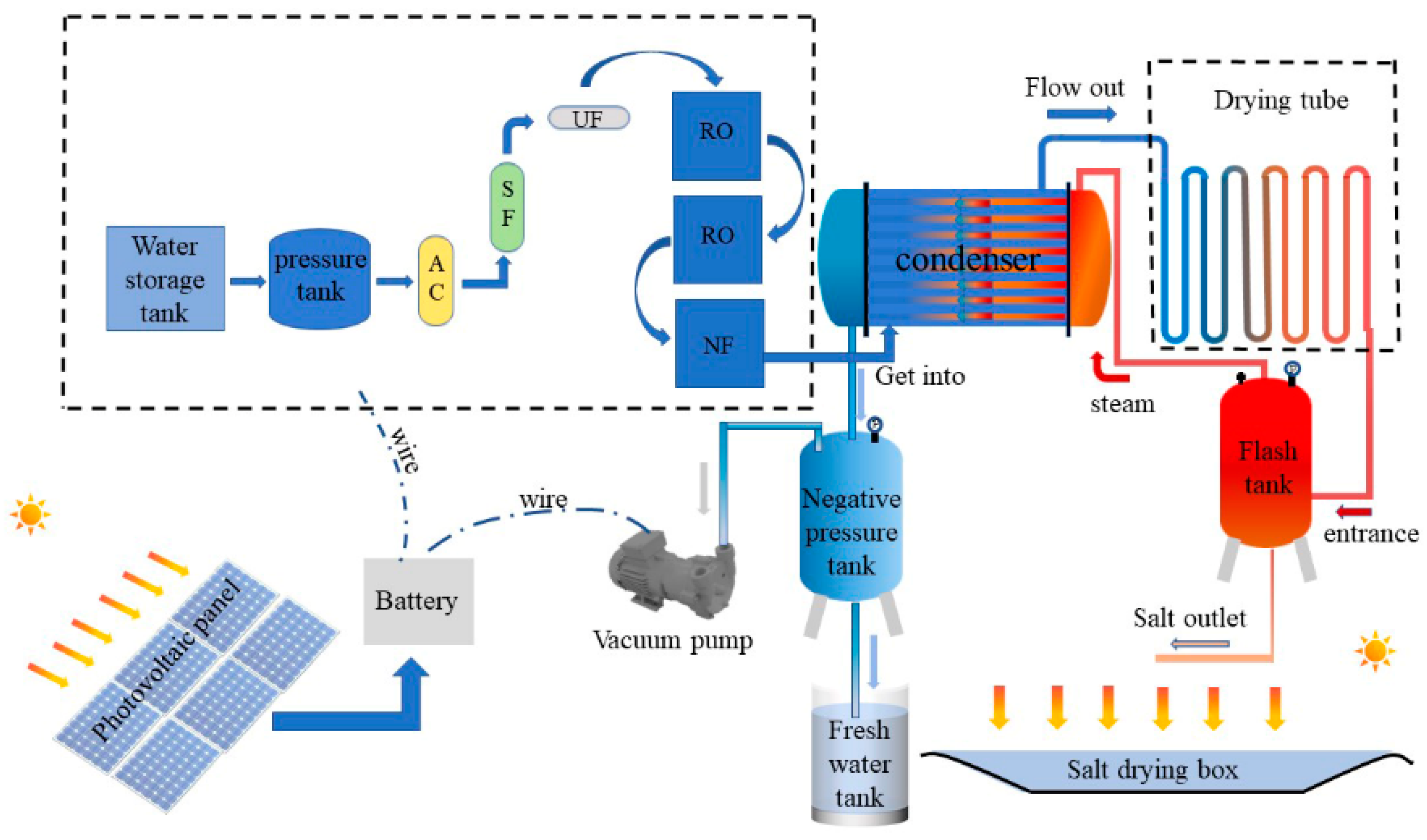
Following the method outlined in Section 2.1, a separation and desalination process was designed for farmland saline-alkaline water. This process consisted of a pretreatment device, a composite NF-RO membrane system, a circulating solar collector tube, a flash tank, a shell-and-tube circulating condenser, and a solar salt box (Figure 2).
- Pretreatment device: Pretreatment technology constitutes an important premise of the composite NF-RO membrane system. The pretreatment technology not only ensures that water quality can meet the requirements of the composite NF-RO membrane system for inlet water quality, it also helps to remove impurities, bacteria, and sediments. The process protects the composite NF-RO membrane system from mechanical damage, guaranteeing long-term, safe, and stable service of the devices, thereby extending the service life of the composite NF-RO membrane system. The pretreatment device is composed of a self-developed quartz sand filter, an activated carbon filter, and an ultrafiltration filter. The activated carbon filter (0.6 m in diameter, 1.2 m in height, and 1.2 m in layer height) filtered particles 1.0–1.5 mm in size. The quartz sand filter, also 0.6 m in diameter, 1.2 m in height, and 1.2 m in layer height, filtered particles 0.8–1.0 mm in size. The ultrafiltration filter, made of PVDF, is 0.16 m in diameter and 0.91 m in height.
- NF-RO device: The NF-RO device is composed of the RO membrane and the NF membrane. The mechanisms by which the RO membrane rejects inorganic ions mainly include the dissolution-diffusion theory, the preferential adsorption theory, and the hydrogen bond theory. The mechanisms by which the NF membrane rejects inorganic ions mainly include the screening theory, the adsorption theory, and the charge repulsion theory. The composite NF-RO membrane system is composed of high-pressure and low-pressure RO membranes and the NF membrane. The specifications of the primary RO membrane, the secondary RO membrane, and the tertiary NF membrane are RM-BW-4040, RM-ULP-4040, and RM-NF-4040, respectively.
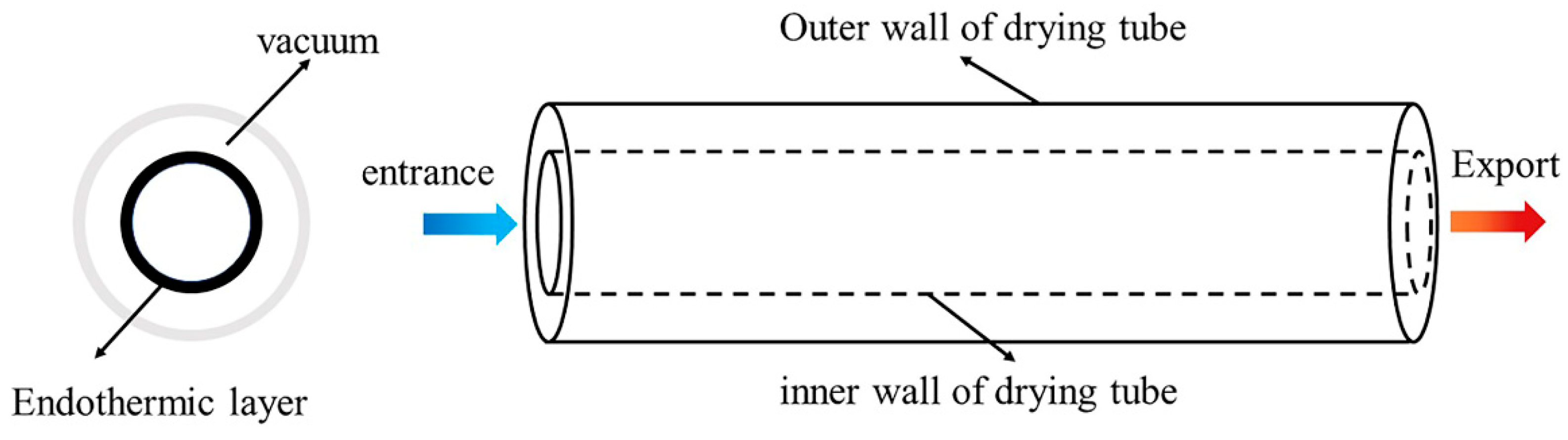
- Circulating solar collector tube: The circulating solar collector tube is made of quartz tubes. Its outer tube, being highly transparent, is 60 mm in diameter, 4 mm in thickness, and 1.2 m in height. The inner tube, coated with a blue film to realize high light absorbance, is 30 mm in diameter, 4 mm in thickness, and 1.2 m in height. A vacuum between the inner and outer tubes enhances light absorption, heat absorption, and thermal insulation performance of the circulating solar collector tube (Figure 3). The circulating solar collector tube is composed of many inclined vacuum tubes arranged in parallel. Solar irradiation on the circulating solar collector tube is converted into thermal energy. Concentrated water entering the circulating solar collector tube constantly absorbs thermal energy from the inner wall. The connection of tubes in a circulating series mode increases the area receiving solar irradiation, so that the temperature of the concentrated water entering the circulating solar collector tube is continuously heated with an increase in tube distance, until boiling.
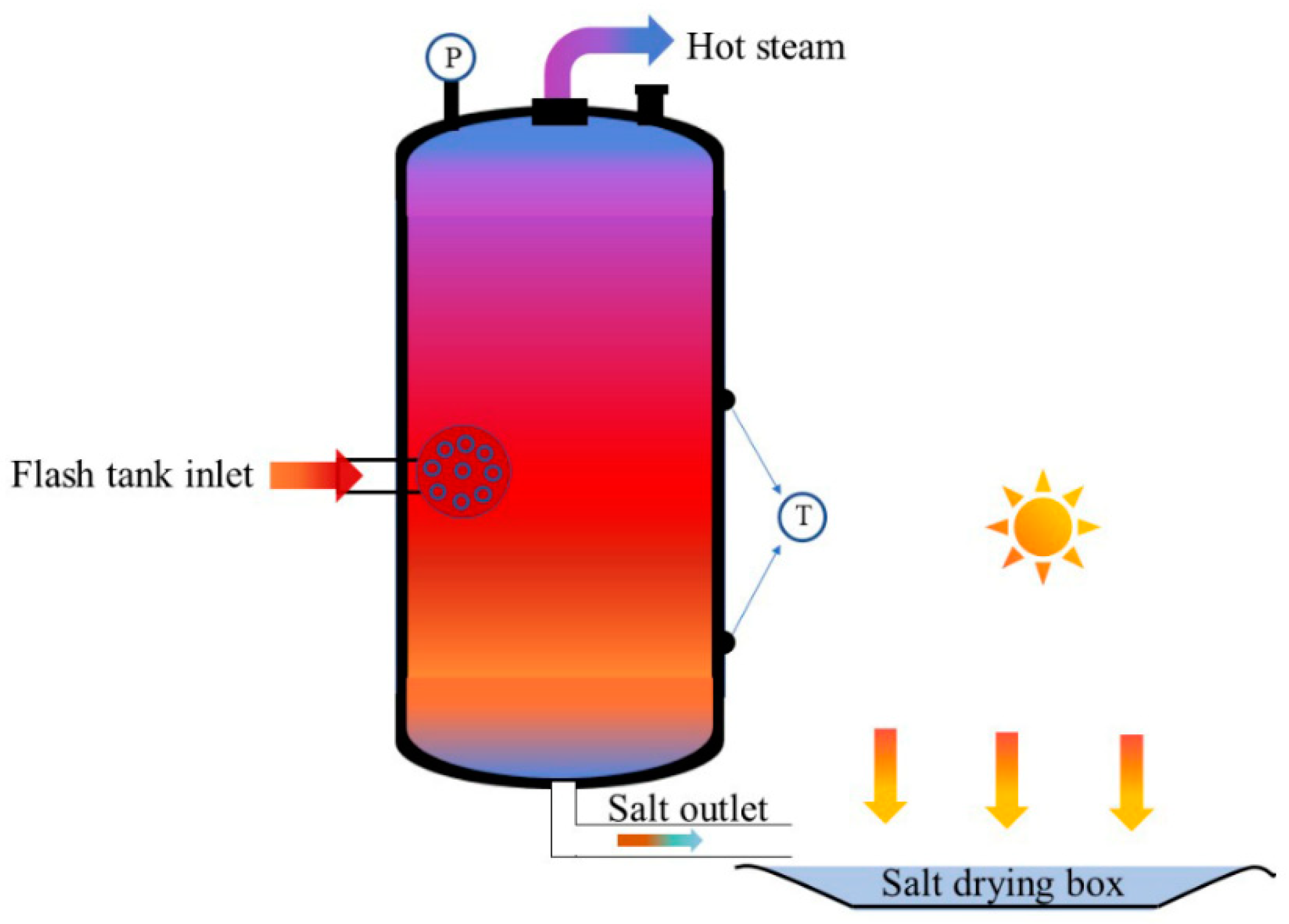
- Flash tank: The flash tank is 0.8 m in diameter and 1.6 m in height. Its internal atomizing nozzle is connected with the outlet of the circulating solar collector tube, and the gas–liquid separation efficiency is increased through turbulent diffusion. Under the action of the water-ring vacuum pump, there is a negative pressure chamber in the flash tank, which lowers the boiling point of the strong brine entering the flash tank. As vapor passes through the air vent at the top of the flash tank, it enters the shell-and-tube circulating condenser. When the concentrate in the flash tank reaches critical salinity, the salt outlet opens and strong brine flows into the solar salt box. Solar salt is then made through brine evaporation in the sun. The structural schematics of the flash tank and the solar salt box are shown in Figure 4.
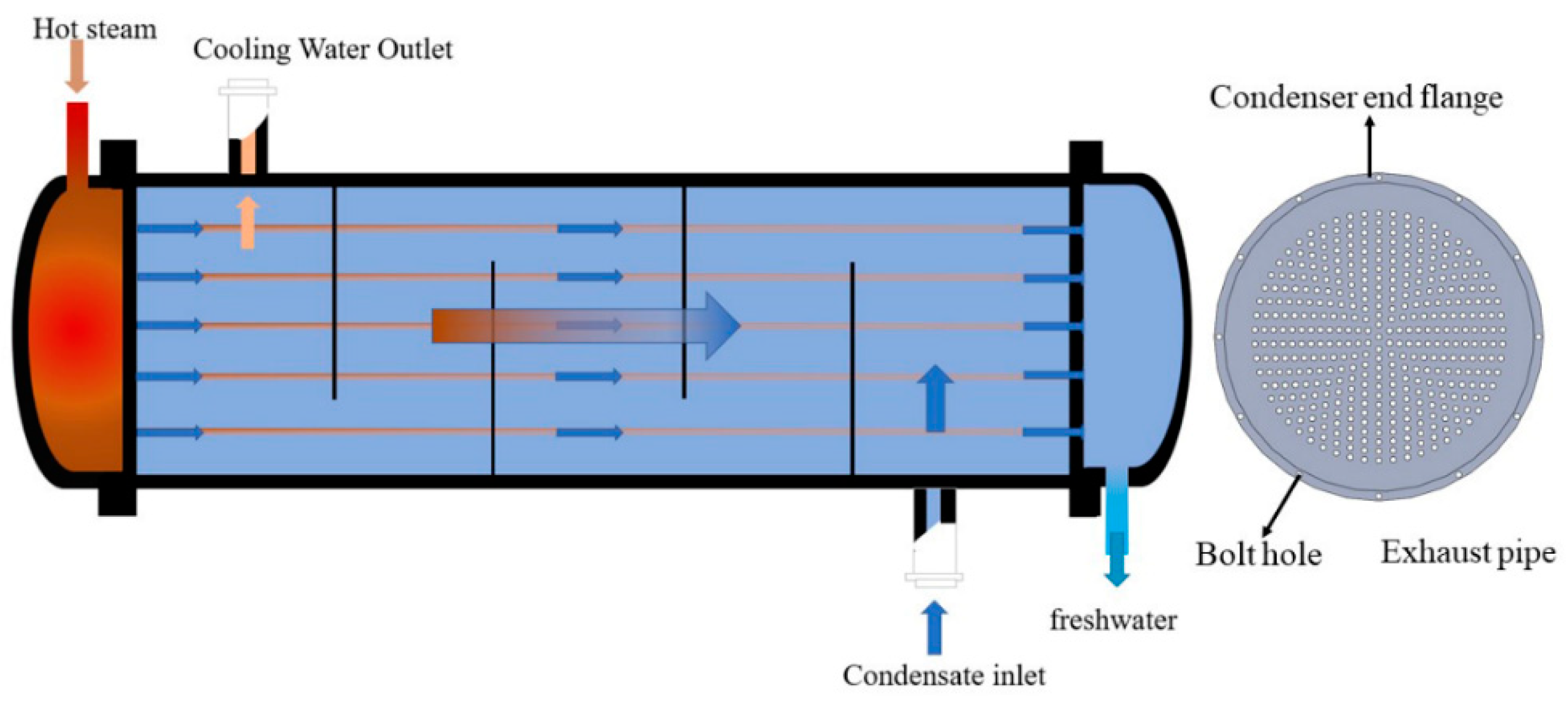
- Shell-and-tube circulating condenser: The shell-and-tube circulating condenser is a general-purpose device used for heat exchange, characterized by high heat transfer efficiency and low flow resistance. The condenser, 0.6 m in diameter and 2.1 m in height, contains a total of 256 heat exchange tubes. Cooling water running between the heat exchange tubes facilitates rapid condensation of the vapor; cooling water flows into the shell-and-tube circulating condenser from the bottom and flows out from the top. As a coolant in continuous supply, cooling water condenses vapor in the shell-and-tube circulating condenser into fresh water. The vapor enters the shell-and-tube circulating condenser via the left inlet and fresh water is discharged via the right outlet. The structure of the shell-and-tube circulating condenser is shown in Figure 5. Under the action of the water-ring vacuum pump, pressure and temperature of the vapor in the shell-and-tube circulating condenser both decline, reducing heat loss of the vapor and increasing the condensation efficiency of the shell-and-tube circulating condenser.
3. Materials and Methods
3.1. Test Materials
Saline-alkaline water analyzed in this study was sampled from the #10 alkali drainage canal of Alar City, Xinjiang (40°39′26.21″ N, 81°23′28.69″ E; 1012 m elevation) in June, 2021, 45 d after spring irrigation. Saline-alkaline water collected from the sampling site was placed under a sunshade on the test site to avoid direct sunshine.
The test site was located at the Soil Tank Laboratory of Tarim University, Alar City, Xinjiang. The test lasted for 12 d (from 6 June to 17 June 2021), consuming a total of 12,000 L saline-alkaline water (1000 L/time × 12 times). Saline-alkaline water was sampled on a daily basis.
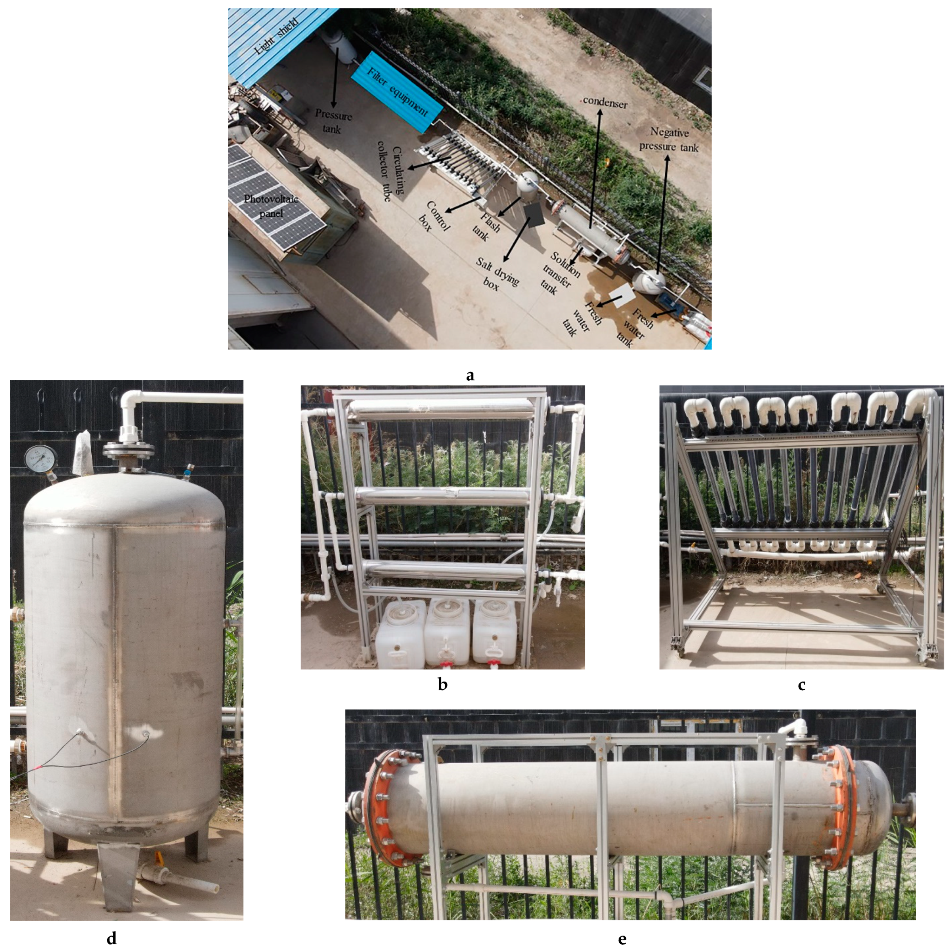
The designed separation and desalination device for farmland saline-alkaline water (Figure 6) had a floor area of 36 m2 (Figure 6a). The NF-RO device was composed of the RO membrane and the NF membrane in series connection, and the effective areas of the RO membrane and the NF membrane were 7.9 m2 and 3.3 m2, respectively (Figure 6b). The circulating solar collector tube assembly, comprising 14 tubes connected in series by U-tubes, was installed in a due south direction with an inclination of 45° (Figure 6c). The flash tank, having a total capacity of 600 L, is shown in Figure 6d, and the shell-and-tube circulating condenser, having a floor area of 16 m2, is shown in Figure 6e.
3.2. Test Methods
3.2.1. Pretreatment Test
Indices used to evaluate whether water yielded by the pretreatment device satisfied the working conditions of the composite NF-RO membrane system included turbidity, the silt density index (SDI), total salinity, and pretreatment water yield. ① Turbidity: saline-alkaline water turbidity and that of water yielded after pretreatment were measured using an industrial turbidimeter (model: SIN-PTU100; measurement precision: ±2% FS; manufactured by Sinomeasure Automation Technology Co., Ltd, Hangzhou, China.). ② SDI: SDI of the saline-alkaline water and that of water yielded after pretreatment were determined using an SDI tester (model: QZDY-SD147; manufactured by Qibote Environmental Science & Technology Co., Ltd, Jiangsu, China.). ③ Total salinity: total salinity of the saline-alkaline water and that of water yielded after pretreatment were measured using a pen-type salimeter (model: AR8012; salinity measurement range: 0–50 ppt; resolution: 0.01 ppt; Smart Instruments Co., Ltd, Jiangsu, China.). ④ Pretreatment water yield: flow rates of the wastewater outlet and water yield outlet of the pretreatment device were measured using a HI2560 flow sensor (flow rate measurement range: 4–45 L/min; pile-up pulse: 1 L = 225 Hz ± 10%; manufactured by Ponai Sensor Science & Technology Co., Ltd, Zhejiang, China).
3.2.2. Comparison of the NF Membrane, the RO Membrane, and the Composite NF-RO Membrane System
Indices used to evaluate the separation and desalination effect of the composite NF-RO membrane system included desalination rate, total hardness, and Cl− content. ① Desalination rate: salinity of the original saline-alkaline water, water yielded by the primary and secondary RO membranes, and water yielded by the tertiary NF membrane were measured using a pen-type salimeter (model: AR8012; salinity measurement range: 0–50 ppt; resolution: 0.01 ppt; Smart Instruments Co., Ltd, Jiangsu, China). ② Total hardness: EDTA titration was used to measure total hardness of the original saline-alkaline water, water yielded by the primary and secondary RO membranes, and water yielded by the tertiary NF membrane. ③ Cl− content: Cl− contents of the original saline-alkaline water, water yielded by the primary and secondary RO membranes, and water yielded by the tertiary NF membrane were measured using an ion chromatograph (model: Integrion; chromatographic column: AS11-HC-4 µm; intelligent high-pressure ion chromatograph manufactured by Thermo Fisher Scientific Inc., Waltham, MA, USA).
3.2.3. Heating Test on the Circulating Solar Collector Tube
(1) Indices used to measure the heating performance of the circulating solar collector tube included flow rate and temperature. ① Flow rate: inlet flow rate of the circulating solar collector tube was measured using an HI2560 flow sensor. ② Temperature was measured using a DS18b20 temperature sensor (temperature measurement range: −55 °C–+125 °C; precision: 9 Bit–12 Bit; manufactured by Senxte Co., Ltd, Jiangsu, China).
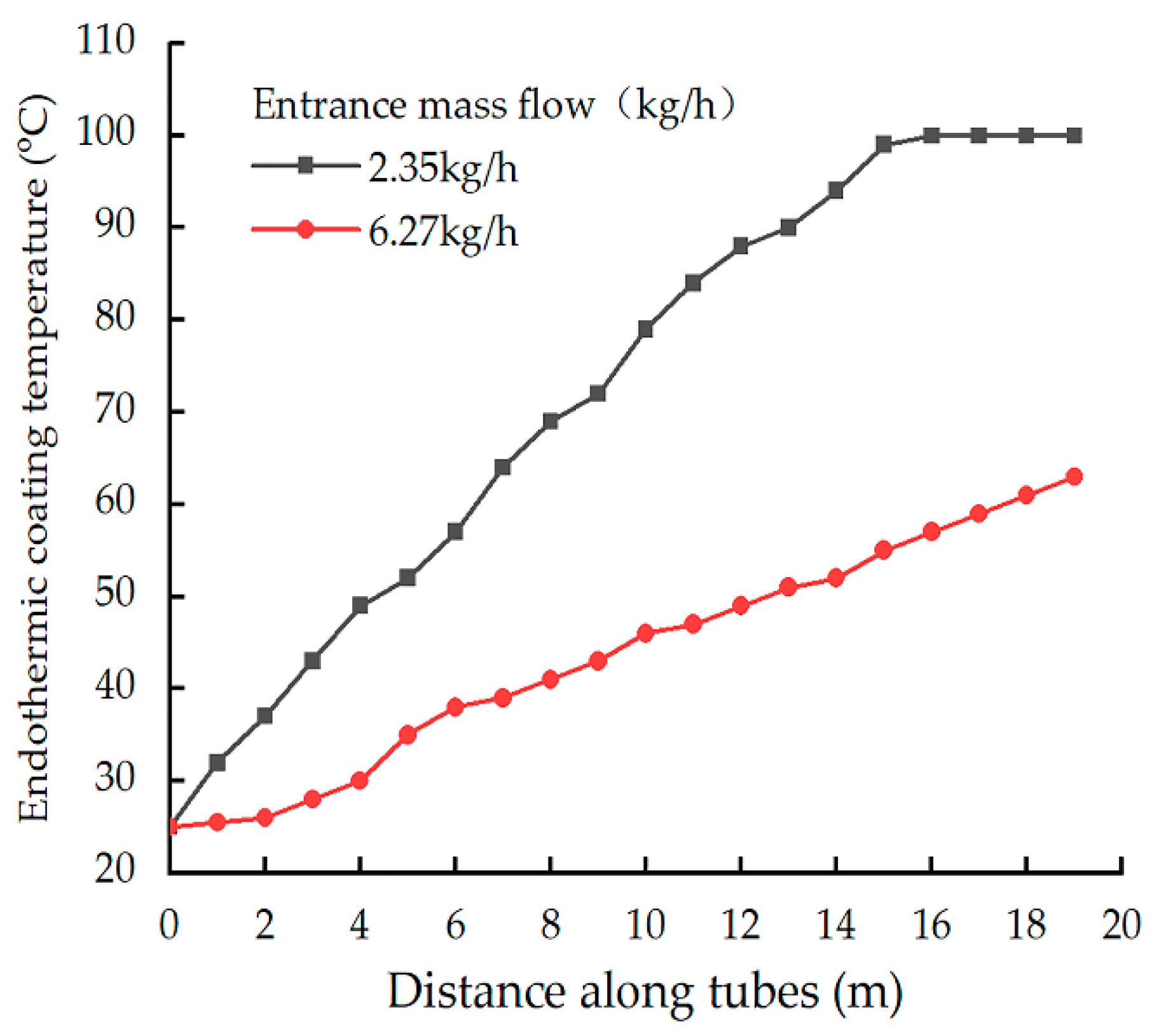
(2) Test conditions: total solar irradiation intensity: 828 W/m2; ambient temperature: 43.4 °C; wind velocity: 4 m/s; inlet water temperature: 25 °C; inlet mass flow rate: 2.35 kg/h and 6.27 kg/h.
3.2.4. Flashing-Condensation Test
(1) The index used to evaluate the effect of the flashing-condensation process was the fresh water recovery rate. The inlet flow rate of the flash tank, the outlet flow rate of the flash tank, and the outlet flow rate of the shell-and-tube circulating condenser were measured using an HI2560 flow sensor. The quantity of the concentrated water flowing from the circulating solar collector tube to the flash tank, the quantity of the concentrate discharged out of the salt outlet of the flash tank, and the quantity of the fresh water flowing out of the fresh water outlet of the shell-and-tube circulating condenser were recorded. Finally, the recovery rate of fresh water was calculated. The pressure of the flash tank was measured using a PT210B-M20 pressure sensor (pressure measurement range: −0.1–2 MPa; measurement precision: 0.5% FS; manufactured by Yunhao Automation Equipment Co., Ltd, Shanghai, China).
(2) Test conditions: The test lasted for 8 d (from 9 June to 16 June 2021, 9:00–20:00). Mean solar irradiation intensity: 573.2 W/m2; vacuum degree: 0.8 bar; flow velocity of the concentrated water into the flash tank: 9.26 mL/s.
3.2.5. Test on Solar Salt Making through Brine Evaporation in the Sun
(1) Indices used to evaluate the effect of solar salt making through brine evaporation in the sun included crystallization rate and crystal components. ① Crystallization rate: crystals were weighed using an electronic balance (model: Pioneer CP series; range: 0–3200 g; measurement precision: 0.001 g; manufactured by Ohaus Instruments Co., Ltd, Jiangsu, China), and relevant data was recorded. ② Crystal components: crystal components were detected using the X-ray diffraction (XRD) method with an X-ray diffractometer (model: D8ADVANCE, manufactured by Bruker (Karlsruhe, Germany); working voltage: 45 kV; working current: 10 mA; continuous scanning angle: 4–80°).
(2) Test conditions: The sample (1 g crystals collected from the solar salt box) was placed in a YHG-500-BS far-infrared rapid drying oven and dried at a constant temperature (105 °C) for 4 h. After surface dampness had been removed, samples were subjected to an XRD test.
3.3. Date Processing and Analysis
Excel 2007 was used for statistical processing of the data obtained in the test. The standard error S was adopted as the water sample’s salinity error.
where is salinity; is the mean value; and n is the number of sampling times.
4. Results and Analysis
4.1. Pretreatment Effect
Salinity of the saline-alkaline water fluctuated within the range of 15,993–17,108 mg/L; and salinity error (S) of the water sample was ±0.34 mg/L. After pretreatment, total salinity of the saline-alkaline water declined by 4.9%, and its turbidity, SDI, and water yield rate were <1, <3, and >95%, respectively. These results satisfied the working conditions of the composite NF-RO membrane system. Test data is shown in Table 1.
4.2. The NF Membrane, the RO Membrane, and the Composite NF-RO Membrane System
After pretreatment, mean salinity, mean total hardness, and mean Cl− content of the saline-alkaline water were 16,032, 1196.4, and 7468.89 mg/L, respectively.
When the RO membrane was only used on the filter of the separation and desalination device, the desalination rate, total hardness removal rate, and Cl− removal rate wete 92.73%, 97.64%, and 96.82%, respectively (Table 2). Mean salinity, mean total hardness, and mean Cl− content of the final water were 1165.53, 28.23, and 509.82 mg/L, respectively.
When the NF membrane was only used on the filter of the separation and desalination device, the desalination rate, total hardness removal rate, and Cl− removal rate were 93.43%, 98.16%, and 97.56%, respectively. Mean salinity, mean total hardness, and mean Cl− content of the final water were 985.97, 22.01, and 182.24 mg/L, respectively.
When the composite NF-RO membrane system was used on the filter of the separation and desalination device, the desalination rate, total hardness removal rate, and Cl− removal rate were 96.06%, 98.93%, and 99.32%, respectively. Mean salinity, mean total hardness, and mean Cl− content of the final water were 631.66, 12.8, and 50.79 mg/L, respectively.
In summary, only using the RO membrane on the filter of the separation and desalination device resulted in water failing to meet the requirements of the Standard for Irrigation Water Quality (GB 5084-2021) (non-saline-alkaline lands: salinity ≤ 1000 mg/L; saline-alkaline lands: salinity ≤ 2000 mg/L, Cl− ≤ 350 mg/L) [31]. Using only the NF membrane resulted in the requirements of the Standard for Irrigation Water Quality (GB 5084-2021) being met. However, when the composite NF-RO membrane system was used for filtration, this system had a better filtering effect than using either the NF membrane or the RO membrane. According to the Donnan effect [32], under the same operating conditions, the rejection rates of inorganic ions by the NF membrane and the RO membrane depend on factors such as the ion radius and ion valency (the higher the ion valency, the more significant the rejection effect). Therefore, total hardness removal rates of the NF membrane and the RO membrane were generally higher than salinity removal rates. Filtration using the composite NF-RO membrane system can satisfy the process demands of the front-end technology of the separation and desalination device for farmland saline-alkaline water.
4.3. Effects of Different Mass Flow Rates on the Temperature of the Endothermic Coating of the Circulating Solar Collector Tube
Temperature changes of the blue-film endothermic coating under the same conditions and different inlet mass flow rates are shown in Figure 7. Here, the temperature of the endothermic coating increased with an increase in the circulating solar collector tube distance, and a positive correlation existed between them. At the same position of the circulating solar collector tube, the temperature of the endothermic coating declined with an increase in inlet mass flow rate, having a negative correlation.
4.4. Condensation Effect of the Shell-and-Tube Circulating Condenser
A HI2560 flow sensor was used to record the quantity of the concentrated water entering the flash tank, the quantity of the concentrate discharged out of the salt outlet of the flash tank, and the quantity of the fresh water flowing out of the fresh water outlet of the shell-and-tube circulating condenser. Test data is shown in Table 3, where “a” denotes the quantity of the concentrated water entering the flash tank (L), “b” denotes the quantity of the concentrate discharged out of the salt outlet of the flash tank (L), and “c” denotes the quantity of the fresh water flowing out of the fresh water outlet of the shell-and-tube circulating condenser (L). The highest, lowest, and mean fresh water recovery rates were 76.85%, 73.99%, and >70%, respectively.
4.5. Effect of Solar Salt Making through Brine Evaporation in the Sun
4.5.1. Crystallization Rate of Concentrate in the Solar Salt Box
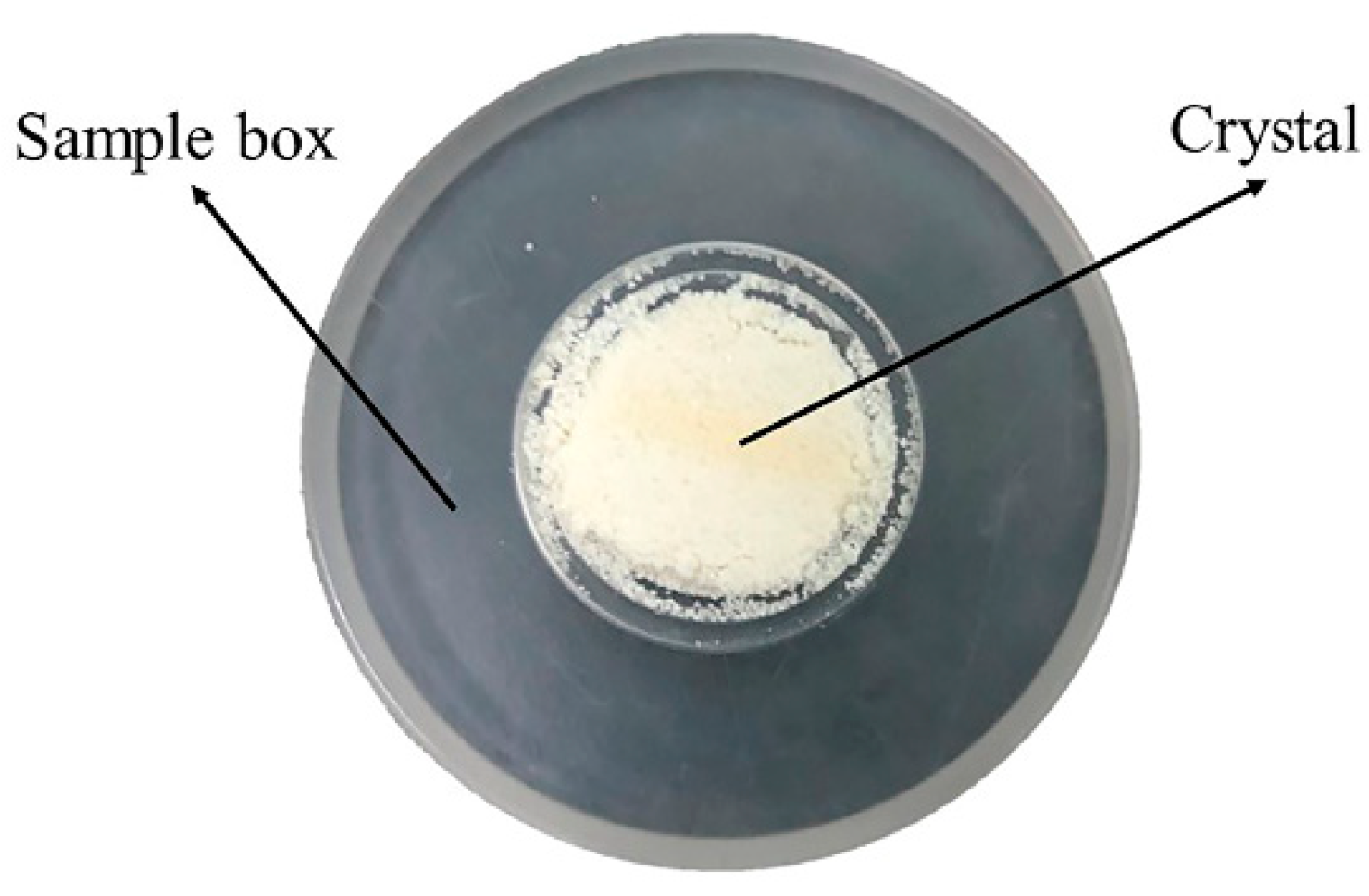
Under the conditions specified in Section 4.4, concentrated water in the solar salt box continuously evaporated and concentrated after absorbing solar irradiation, eventually forming crystals (Figure 8). Using solar energy (a clean energy) not only protects the environment, it also saves resources. In Table 4, “a” is the theoretical crystallization weight (kg), and “b” is the actual crystallization weight (kg). In the crystallization process of the concentrated water, the highest, lowest, and mean precipitation rates of crystals were 98.13%, 95.94%, and >95%, respectively.
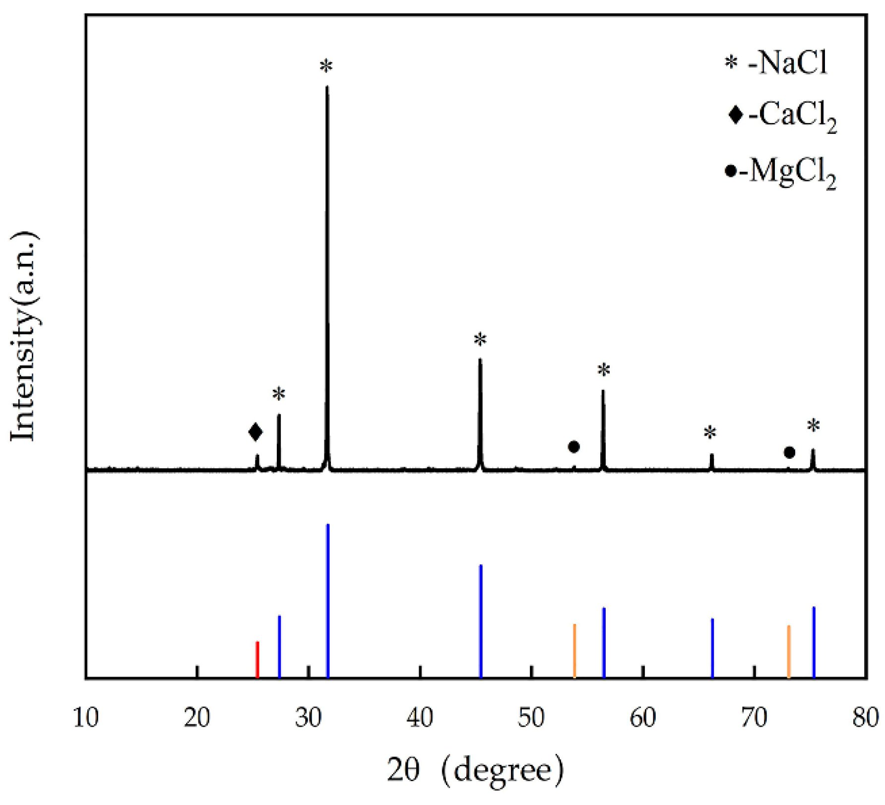
4.5.2. Crystallization Rate of the Concentrate in the Solar Salt Box
The XRD diagram of crystallization of the concentrated water is shown in Figure 9. Here, the comparison between XRD data and the PDF standard card produced a good peak goodness of fit. XRD data of crystals were processed using MDI Jade 6 software. The primary compound of crystals precipitated was NaCl (with a relative content of 93%), and there were also small quantities of CaCl2 and MgCl2 (with a relative content of 7%). Crystals obtained by the production of solar salt through brine evaporation in the sun also have the potential values of industrial salts. In the membrane filtration test on the separation and desalination device for farmland saline-alkaline water, the instable working pressure of the membranes resulted in the incomplete removal of bivalent cations Ca2+ and Mg2+. Therefore, ensuring the stable working pressure of the membranes in subsequent process optimization will improve the effect of bivalent cation removal from saline-alkaline water by membranes.
4.6. Treatment Effect of the Separation and Desalination Process for Saline-Alkaline Water
When the device was in stable service, total salinity of the saline-alkaline water after pretreatment declined by 4.9%, and its turbidity, SDI, and water yield rate were <1, <3, and ≥95%, respectively. These results satisfied the working conditions of the composite NF-RO membrane system. Filtration by the composite NF-RO membrane system compensated for the shortages of the NF membrane and the RO membrane when they were solely used. After filtration by the composite NF-RO membrane system, mean salinity, mean total hardness, and mean Cl content of the final water yielded were 631.66, 12.8, and 50.79 mg/L, respectively. The composite NF-RO membrane system not only met the requirements of the Standard for Irrigation Water Quality (GB 5084-2021) (non-saline-alkaline lands: salinity ≤ 1000 mg/L; saline-alkaline lands: salinity ≤ 2000 mg/L, Cl− ≤ 350 mg/L) [31], it also satisfied the specifications of the Standards for Drinking Water Quality (GB 5749-2006) (total dissolved solids ≤ 1000 mg/L, Cl− ≤ 250 mg/L, total hardness ≤ 450 mg/L) [33]. The fresh water recovery rate of the flashing-condensation process was 74.83%, and the crystals in the solar salt box weighed about 6.9 kg/d. With respect to farmland saline-alkali water in the saline-alkali water separation and desalination process, the water production of equipment at all levels is shown in Table 5.
5. Discussion
5.1. Effect Analysis of the Separation and Desalination Process for Saline-Alkaline Water
Pretreatment helps to protect the composite NF-RO membrane system from mechanical damage, guaranteeing its long-term use, safe operation, and stability, in addition to extending the service life of the composite NF-RO membrane system. When the composite NF-RO membrane system was used in this study, total salinity, total hardness, and Cl− content of water yielded all met the requirements of the Standard for Irrigation Water Quality (GB 5084-2021) (non-saline-alkaline lands: salinity ≤ 1000 mg/L; saline-alkaline lands: salinity ≤ 2000 mg/L, Cl− ≤ 350 mg/L) [31]. The total desalination rate (96%) also satisfied the process demands of the front-end technology of the separation and desalination device for farmland saline-alkaline water. The circulating solar collector tube, as the external heat source of the flash tank, directly affected flash efficiency. That is, the higher the temperature of the concentrated water in the circulating solar collector tube, the more obvious the phenomenon of gas–liquid separation in the flash tank, and the higher the flash efficiency. The temperature of the concentrated water in the circulating solar collector tube declined with an increase in the flow velocity of the concentrated water, and heat-collecting efficiency increased as the flow rate increased. The atomizing nozzle mounted in the flash tank increased the gas–liquid separation efficiency of the concentrated water entering the flash tank according to the principle of turbulent diffusion. The action of the vacuum pump produced negative pressure chambers in the flash tank and the shell-and-tube circulating condenser, which not only lowered the boiling point of the concentrated water in the flash tank, but also increased flash efficiency, condensation efficiency, and fresh water recovery rate (>70%). In conclusion, the key components of the separation and desalination device for farmland saline-alkaline water can meet relevant process demands.
5.2. Comparison between the Separation and Desalination Process for Farmland Saline-Alkaline Water and the Seawater Desalination Process
By adopting different processes, existing seawater desalination devices were found to differ from each other in terms of energy consumption, cost, frequency, and yield. ① MSF [34] devices require a stable external heat source, they incur huge energy consumption, and they have a low yield. ② HDH [35] devices are expensive, involve complex process flows, and cause substantial heat losses. ③ The core components used for membrane distillation [36] are expensive and need to be frequently replaced, inevitably increasing the overall cost of water yield. ④ Although solar distillation [37] devices have simple processes, they are restricted by high area demand and low efficiency. In contrast, the separation and desalination process for farmland saline-alkaline water proposed in this study not only helps to control costs, it also guarantees a yield of sufficient agricultural irrigation water without chemical treatment. The crystals obtained by solar salt making through brine evaporation also have the potential values of industrial salts. This process not only realizes the reutilization of water resources and crystals, it also offers reasonable solutions to the problems of the shortage of agricultural irrigation water and the salination of soil faced by arid areas.
5.3. Application Prospects of the Separation and Desalination Process for Farmland Saline-Alkaline Water
The separation and desalination process for farmland saline-alkaline water is a relatively new technique in the field of saline-alkaline water separation and desalination. When water yielded by this process is used for farmland irrigation, it not only mitigates soil salination and water resource shortages, it also realizes the increase in grain yield and the reutilization of water resources. Saline-alkaline land distributed in the irrigation district of Xinjiang account for 37.72% of the total area of farmlands in the irrigation district [38]; globally, saline-alkaline farmlands account for 6% of the total area of the world’s arable land [39]. Thus, the separation and desalination process for farmland saline-alkaline water presents significant potential and promising prospects in the field of saline-alkaline water separation and desalination.
6. Conclusions
Based on the separation and desalination test of saline-alkali water in farmland, we found that after pretreatment, the total salinity of the saline-alkaline water declined by 4.9%, and its turbidity, SDI, and water yield rate were <1, <3, and 95%, respectively, which increased the service life of the membrane. We also found that the combination of NF and RO membrane had a better filtration effect than the single NF membrane and the single RO membrane, which could make up for the deficiency of single membrane filtration and improve the filtration effect of the membrane. When this was used for filtering saline-alkaline water, the composite NF-RO membrane system achieved a desalination rate of 96.06%, a total hardness removal rate of 98.93%, and a Cl− removal rate of 99.32%. Mean salinity, mean total hardness, and mean Cl− content of the final water yielded were 631.66, 12.8, and 50.79 mg/L, respectively. In flash condensation technology, the application of a vacuum pump reduces the boiling point of concentrated water in the flash tank and improves the efficiency of flash and condensation; herein, the recovery rate of fresh water was more than 70%. It was ascertained that the primary compound of precipitated crystals was NaCl (with a relative content of 93%), and that there were also small quantities of CaCl2 and MgCl2 (with a relative content of 7%). These results suggest that the precipitates have the potential values of industrial salts, and can thus be utilized.
Author Contributions
Resources, Z.S.; data curation, J.Z.; writing—original draft preparation, Q.Y.; writing—review and editing, C.H. and X.Y.; visualization, J.L.; supervision, Y.H.; project administration, X.Y. All authors have read and agreed to the published version of the manuscript.
Funding
This work was supported by major scientific and technological projects of Xinjiang Construction Corps, grant number 2018AA003, Graduate innovation project of Tarim University, grant number TDGRI202039, The innovative research project of Tarim University president Foundation, grant number TDZKCX202103.
Institutional Review Board Statement
Not applicable.
Informed Consent Statement
Not applicable.
Data Availability Statement
The data presented in this study are available on request from the corresponding author.
Acknowledgments
This work was supported by major scientific and technological projects of Xinjiang Construction Corps (Project No. 2018AA003), Graduate innovation project of Tarim University (Project No. TDGRI202039), The innovative research project of Tarim University president Foundation, (Project No. TDZKCX202103). The authors are grateful to anonymous reviewers for their comments.
Conflicts of Interest
The authors declare no conflict of interest.
References
- Zhang, K.W.; Song, J.L.; Chen, X.G.; Yin, T.T.; Liu, C.B.; Li, K.P.; Zhang, J.R. Expression of the Thellungiella halophila vacuolar H+-pyrophosphatase gene (TsVP) in cotton improves salinity tolerance and increases seed cotton yield in a saline field. Euphytica 2016, 211, 231–244. [Google Scholar] [CrossRef]
- Wang, C.X.; Wang, Q.J.; Liu, J.J.; Su, L.J.; Dan, Y.Y.; Zhuang, L. Effects of mineralization of irrigation water and soil salinity on cotton emergence rate in Southern Xinjiang. Trans. Chin. Soc. Agric. Eng. Trans. CSAE 2010, 26, 28–33. [Google Scholar]
- Gopalakrishnan, T.; Kumar, L. Linking Long-Term Changes in Soil Salinity to Paddy Land Abandonment in Jaffna Peninsula, Sri Lanka. Agriculture 2021, 11, 211. [Google Scholar] [CrossRef]
- Hamdi, L.; Suleiman, A.; Hoogenboom, G.; Shelia, V. Response of the Durum Wheat Cultivar Um Qais (Triticum turgidum subsp. durum) to Salinity. Agriculture 2019, 9, 135. [Google Scholar] [CrossRef] [Green Version]
- Liu, L.; Wang, B. Protection of Halophytes and Their Uses for Cultivation of Saline-Alkali Soil in China. Biology 2021, 10, 353. [Google Scholar] [CrossRef] [PubMed]
- Hao, S.; Wang, Y.; Yan, Y.; Liu, Y.; Wang, J.; Chen, S. A Review on Plant Responses to Salt Stress and Their Mechanisms of Salt Resistance. Horticulturae 2021, 7, 132. [Google Scholar] [CrossRef]
- Hu, M.F.; Tian, C.L.; Zhao, Z.Y.; Wang, L.X. Salinization causes and research progress of technologies improving saline-alkali soil in Xinjiang. J. Northwest A F Univ. 2012, 40, 111–117. [Google Scholar] [CrossRef]
- Li, L.; Liu, H.; He, X.; Lin, E.; Yang, G. Winter Irrigation Effects on Soil Moisture, Temperature and Salinity, and on Cotton Growth in Salinized Fields in Northern Xinjiang, China. Sustainability 2020, 12, 7573. [Google Scholar] [CrossRef]
- Li, J.; He, Z.B.; Du, J.; Chen, L.F.; Lin, P.F.; Zhu, X.; Fang, S.; Zhao, M.M.; Tian, Q.Y. Effects of winter irrigation on soil hydro-thermal features in desert oasis farmland in arid area during freezing and thawing period. Trans. Chin. Soc. Agric. Eng. Trans. CSAE 2018, 34, 105–112. [Google Scholar] [CrossRef]
- Liu, Z.P.; Jiao, X.Y.; Lu, S.H.; Zhu, C.L.; Zhai, Y.M.; Guo, W.H. Effects of winter irrigation on soil salinity and jujube growth in arid regions. PLoS ONE 2019, 14, 6. [Google Scholar] [CrossRef] [Green Version]
- Zhao, L.; Heng, T.; Yang, L.; Xu, X.; Feng, Y. Study on the Farmland Improvement Effect of Drainage Measures under Film Mulch with Drip Irrigation in Saline–Alkali Land in Arid Areas. Sustainability 2021, 13, 4159. [Google Scholar] [CrossRef]
- Xiao, C.; Li, M.; Fan, J.; Zhang, F.; Li, Y.; Cheng, H.; Li, Y.; Hou, X.; Chen, J. Salt Leaching with Brackish Water during Growing Season Improves Cotton Growth and Productivity, Water Use Efficiency and Soil Sustainability in Southern Xinjiang. Water 2021, 13, 2602. [Google Scholar] [CrossRef]
- Zikalala, P.; Kisekka, I.; Grismer, M. Calibration and Global Sensitivity Analysis for a Salinity Model Used in Evaluating Fields Irrigated with Treated Wastewater in the Salinas Valley. Agriculture 2019, 9, 31. [Google Scholar] [CrossRef] [Green Version]
- Feng, W.; Gao, J.; Cen, R.; Yang, F.; He, Z.; Wu, J.; Miao, Q.; Liao, H. Effects of Polyacrylamide-Based Super Absorbent Polymer and Corn Straw Biochar on the Arid and Semi-Arid Salinized Soil. Agriculture 2020, 10, 519. [Google Scholar] [CrossRef]
- Fouda, A.; Nada, S.; Elattar, H.; Rubaiee, S.; Al-Zahrani, A. Performance analysis of proposed solar HDH water desalination systems for hot and humid climate cities. Appl. Therm. Eng. 2018, 144, 81–95. [Google Scholar] [CrossRef]
- Kabeel, A.E.; Dawood, M.M.K.; Ramzy, K.; Nabil, T.; Elnaghi, B.; Elkassar, A. Enhancement of single solar still integrated with solar dishes: An experimental approach. Energy Convers. Manag. 2019, 196, 165–174. [Google Scholar] [CrossRef]
- Baig, H.; Antar, M.A.; Zubair, S.M. Performance evaluation of a once-through multi-stage flash distillation system: Impact of brine heater fouling. Energy Convers. Manag. 2011, 52, 1414–1425. [Google Scholar] [CrossRef]
- Gao, H.H.; Jiang, A.; Huang, Q.Y.; Xia, Y.D.; Gao, F.R.; Wang, J. Mode-Based Analysis and Optimal Operation of MSF Desalination System. Processes 2020, 8, 794. [Google Scholar] [CrossRef]
- Zubair, S.M.; Antar, M.A.; Elmutasim, S.M.; Lawal, D.U. Performance evaluation of humidification-dehumidification (HDH) desalination systems with and without heat recovery options: An experimental and theoretical investigation. Desalination 2018, 436, 161–175. [Google Scholar] [CrossRef]
- Alsehli, M. A New Approach to Solar Desalination Using a Humidification–Dehumidification Process for Remote Areas. Processes 2021, 9, 1120. [Google Scholar] [CrossRef]
- Cho, K.L.; Hill, A.J.; Caruso, F.; Kentish, S.E. Chlorine resistant glutaraldehyde crosslinked polyelectrolyte multilayer membranes for desalination. Adv. Mater. 2015, 27, 2791–2796. [Google Scholar] [CrossRef] [PubMed]
- Diaby, A.T.; Byrne, P.; Loulergue, P.; Sow, O.; Maré, T. Experimental Study of a Heat Pump for Simultaneous Cooling and Desalination by Membrane Distillation. Membranes 2021, 11, 725. [Google Scholar] [CrossRef]
- Feria-Díaz, J.J.; Correa-Mahecha, F.; López-Méndez, M.C.; Rodríguez-Miranda, J.P.; Barrera-Rojas, J. Recent Desalination Technologies by Hybridization and Integration with Reverse Osmosis: A Review. Water 2021, 13, 1369. [Google Scholar] [CrossRef]
- Mamouri, S.J.; Derami, H.G.; Ghiasi, M.; Shafill, M.B.; Shiee, Z. Experimental investigation of the effect of using thermosyphon heat pipes and vacuum glass on the performance of solar stil. Energy 2014, 75, 501–507. [Google Scholar] [CrossRef]
- Mosleh, H.J.; Mamouri, S.J.; Shafii, M.B.; Sima, A.H. A new desalination system using a combination of heat pipe, evacuated tube and parabolic trough collector. Energy Convers. Manag. 2015, 99, 141–150. [Google Scholar] [CrossRef]
- Sun, Z.L.; Hu, Q.Y.; Tu, W.R.; Fang, S.B.; Yang, Y. Heat transfer characteristics in circulating solar heat tubes based on gas-liquid two-phase flow. Trans. Chin. Soc. Agric. Eng. Trans. CSAE 2019, 35, 246–254. [Google Scholar] [CrossRef]
- Lacroix, C.; Perier-Muzet, M.; Stitou, D. Dynamic Modeling and Preliminary Performance Analysis of a New Solar Thermal Reverse Osmosis Desalination Process. Energies 2019, 12, 4015. [Google Scholar] [CrossRef] [Green Version]
- Toth, A.J. Modelling and Optimisation of Multi-Stage Flash Distillation and Reverse Osmosis for Desalination of Saline Process Wastewater Sources. Membranes 2020, 10, 265. [Google Scholar] [CrossRef]
- Wang, Z.; Zhang, Y.; Wang, T.; Zhang, B.; Ma, H. Design and Energy Consumption Analysis of Small Reverse Osmosis Seawater Desalination Equipment. Energies 2021, 14, 2275. [Google Scholar] [CrossRef]
- Tian, J.; Zhao, X.; Gao, S.; Wang, X.; Zhang, R. Progress in Research and Application of Nanofiltration (NF) Technology for Brackish Water Treatment. Membranes 2021, 11, 662. [Google Scholar] [CrossRef]
- GB 5084-2021, Standard for Irrigation Water Quality in China. Ministry of Ecology and Environment of the People’s Republic of China. Available online: www.mee.gov.cn/ywgz/fgbz/bz/bzwb/shjbh/shjzlbz/202102/t20210209_821075.shtml (accessed on 1 July 2021).
- Szymczyk, A.; Fievet, P. Ion transport through nanofiltraion membranes: The steric, electric and dielectric exclusion mode. Desalination 2006, 200, 122–124. [Google Scholar] [CrossRef]
- GB 5749-2006, Standards for Drinking Water Quality in China. National Health Commission of the People’s Republic of China. Available online: http://www.nhc.gov.cn/cms-search/xxgk/getManuscriptXxgk.htm?id=30005 (accessed on 18 June 2007).
- Mezher, T.; Fath, H.; Abbas, Z.; Khaled, A. Techno-economic assessment and environmental impacts of desalination technologies. Desalination 2011, 266, 263–273. [Google Scholar] [CrossRef]
- Nafey, A.S.; Fath, H.E.S.; El-Helaby, S.O.; Soliman, A. Solar desalination using humidification–dehumidification processes. Part II. An experimental investigation. Energy Convers. Manag. 2004, 45, 1263–1277. [Google Scholar] [CrossRef]
- Khayet, M. Solar desalination by membrane distillation: Dispersion in energy consumption analysis and water production costs (a review). Desalination 2012, 308, 89–101. [Google Scholar] [CrossRef]
- Subramani, A.; Badruzzaman, M.; Oppenheimer, J.; Jacangelo, J.G. Energy minimization strategies and renewable energy utilization for desalination: A review. Water Res. 2011, 45, 1907–1920. [Google Scholar] [CrossRef]
- He, P.R.; Zhang, F.C.; Hou, X.H.; Liu, N.J.; Meng, X.C.; Zhang, C.Y.; Cheng, H.L. Effects of Soil Water Regulation on Cotton Yield and Soil Water-Salt Distribution under Drip Irrigation in Southern Xinjiang. Res. Soil Water Conserv. 2020, 27, 84–92. [Google Scholar] [CrossRef]
- Ali-Karaghouli, A.; Kazmerski, L.L. Energy consumption and water production cost of conventional and renewable-energy-powered desalination processes. Renew. Sustain. Energy Rev. 2013, 24, 343–356. [Google Scholar] [CrossRef]
Figure 1.
Process flow chart of farmland saline alkaline water separation and desalination.

Figure 2.
Schematic diagram of farmland saline alkaline water separation and desalination process.

Figure 3.
Schematic diagram of circulating solar collector tube.

Figure 4.
Structural diagram of flash tank and salt drying tank.

Figure 5.
Structural diagram of shell-and-tube circulating condenser.

Figure 6.
Installation environment of farmland saline alkaline water separation and desalination device: (a) general drawing of farmland saline alkaline water separation and desalination unit; (b) NF-RO device; (c) circulating solar collector tube; (d) flash tank; (e) shell-and-tube circulating condenser.

Figure 7.
Measured temperature change of the endothermic layer.

Figure 8.
Concentrated water crystal after salt drying.

Figure 9.
X-ray diffraction pattern of crystal in the salt drying box.


Table 1.
Quality of saline-alkaline water before and after pretreatment.
| Project | Saline-Alkaline Water | Saline-Alkaline Water after Pretreatment |
|---|---|---|
| Total salt (mg/L) | 15,993–17,108 | 15,193–16,253 |
| Turbidity (NTU) | 4.5–7.9 | <1 |
| SDI | 5.5–6.7 | <3 |
Table 2.
Filtration effect of nanofiltration reverse osmosis membrane.
| Test Items | RO Membrane | NF Membrane | NF-RO Membrane | ||||||
|---|---|---|---|---|---|---|---|---|---|
| Primary RO Water Production | Secondary RO Water Production | Tertiary RO Water Production | Primary NF Water Production | Secondary NF Water Production | Tertiary NF Water Production | Primary NF-RO Water Production | Primary NF-RO Water Production | Primary NF-RO Water Production | |
| Desalination rate (%) | 28.94 | 66.48 | 92.73 | 32.18 | 68.73 | 93.85 | 29.81 | 65.72 | 96.06 |
| Total hardness removal rate (%) | 88.92 | 95.83 | 97.64 | 91.63 | 96.82 | 98.16 | 89.63 | 95.69 | 98.93 |
| Cl− removal rate (%) | 76.82 | 90.13 | 96.82 | 78.24 | 90.24 | 97.56 | 77.61 | 89.56 | 99.32 |
Table 3.
Recovery rate of fresh water.
| Time (d) | 1 | 2 | 3 | 4 | 5 | 6 | 7 | 8 |
|---|---|---|---|---|---|---|---|---|
| Total amount of concentrated water flowing into flash tank (a) | 396 | 387 | 402 | 389 | 400 | 392 | 406 | 398 |
| Total amount of concentrated water discharged from the salt outlet of flash tank (b) | 92 | 93 | 84 | 85 | 90 | 83 | 79 | 92 |
| Total amount of fresh water discharged from fresh water outlet of shell and tube circulating condenser (c) | 293 | 285 | 904 | 291 | 301 | 297 | 312 | 296 |
| Fresh water recovery (c/a) | 73.99% | 73.64% | 75.62% | 74.81% | 75.25% | 75.76% | 76.85% | 74.37% |
Table 4.
Crystal precipitation effect.
| Time (d) | 1 | 2 | 3 | 4 | 5 | 6 | 7 | 8 |
|---|---|---|---|---|---|---|---|---|
| Theoretical crystallization weight (a) | 7.16 | 6.99 | 6.94 | 7.27 | 7.03 | 7.23 | 7.09 | 7.34 |
| Actual crystallization weight (b) | 6.87 | 6.75 | 6.81 | 7.04 | 6.84 | 6.97 | 6.87 | 7.16 |
| Crystallization rate (b/a) | 95.94% | 96.57% | 98.13% | 96.84% | 97.29% | 96.41% | 96.89% | 97.54% |
Table 5.
Water production at all levels of equipment.
| Project | The Total Amount of Saline-Alkali Water Used in the Test | Wastewater from Pretreatment | Pre-Treated Water | Equipment Loss | ||
|---|---|---|---|---|---|---|
| Fresh Water Produced by NF-RO Equipment | Concentrated Water Produced by NF-RO Equipment | |||||
| Concentrated Water Produced by Flash Tank | Fresh Water of Shell-and-Tube Circulating Condenser | |||||
| Device flow at all levels (L/d) | 1000 | 57.43 | 538.69 | 87.25 | 297.38 | 19.25 |
Publisher’s Note: MDPI stays neutral with regard to jurisdictional claims in published maps and institutional affiliations. |
© 2021 by the authors. Licensee MDPI, Basel, Switzerland. This article is an open access article distributed under the terms and conditions of the Creative Commons Attribution (CC BY) license (https://creativecommons.org/licenses/by/4.0/).
Share and Cite
MDPI and ACS Style
Yang, Q.; Hu, C.; Li, J.; Yi, X.; He, Y.; Zhang, J.; Sun, Z. A Separation and Desalination Process for Farmland Saline-Alkaline Water. Agriculture 2021, 11, 1001. https://0-doi-org.brum.beds.ac.uk/10.3390/agriculture11101001
AMA Style
Yang Q, Hu C, Li J, Yi X, He Y, Zhang J, Sun Z. A Separation and Desalination Process for Farmland Saline-Alkaline Water. Agriculture. 2021; 11(10):1001. https://0-doi-org.brum.beds.ac.uk/10.3390/agriculture11101001
Chicago/Turabian StyleYang, Qiaonan, Can Hu, Jie Li, Xiaokang Yi, Yichuan He, Jie Zhang, and Zhilin Sun. 2021. "A Separation and Desalination Process for Farmland Saline-Alkaline Water" Agriculture 11, no. 10: 1001. https://0-doi-org.brum.beds.ac.uk/10.3390/agriculture11101001
Note that from the first issue of 2016, this journal uses article numbers instead of page numbers. See further details here.