
Design of Stretchable Style Pick-Up Device for Tomato Seedling Transplanters

College of Mechnical and Electrical Engineering, Shihezi University, Shihezi 832003, China
*
Author to whom correspondence should be addressed.
Agriculture 2022, 12(5), 707; https://doi.org/10.3390/agriculture12050707
Submission received: 13 April 2022
/
Revised: 13 May 2022
/
Accepted: 13 May 2022
/
Published: 17 May 2022
(This article belongs to the Special Issue Advances in Agricultural Engineering Technologies and Application)
Abstract
:To solve tomato planting problems, such as high labor intensity and low efficiency, we designed a stretchable style pick-up device, which met the requirements of whole-row picking and improved the efficiency and speed of seedling picking. We designed the parts of the device according to the height of the seedlings and the size of the tray. Seedling analysis was carried out and a parametric model created. Additionally, an evaluation of seedling picking was developed, which included both parallel and vertical displacement. We manufactured the parts according to the simulation parameters, which were optimized by ADAMS. The parts were assembled and the trajectory test carried out. When whole-row seedlings were grown for 30 days, the moisture content was 65.21%, the picking success rate was 92.19%, leaf damage rate was 3.13%, and the substrate damage rate was 1.54%. The study can provide a reference for the design of automatic tomato transplanters.
1. Introduction
Tomatoes are widely grown in northwest China [1,2,3]; currently, people usually adopt a pattern in which seedlings growing in a plastic tray are transplanted. The single seedling transplanting method cannot meet the requirements for large-scale planting, while the whole-row seedling picking can improve the efficiency [4]. The pick-up device is one of the most important parts in the transplanters. At present, the main problems of seedling picking are low precision and high seedling damage [5].
The Pearson model in the UK and Futura in Italy [6] are the main transplanters commonly used in European countries; both adopt a clip-type pick-up device. With the ejection working, the device can pick the seedlings automatically and effectively [7,8]. In China, there are three different types of the pick-up device: the first type with a style that rotates back and forth [9,10,11], the second is telescopic pointer clip-type [12,13,14], and the third category uses other methods, such as pushing down [15], air blowing [16], vibration, or a combination of these [17]. Based on the first type, Jinxin [18] proposed a method of seedling picking that has a track similar to the Woodpecker. This kind of device can realize the picking motion applied in different vegetables. With complex structure and less picking quantity, its working efficiency is limited. Concerning the second pick-up method, Zhang [19] designed a three-finger-type device according to the TRIZ theory, relying on the cylinder pushing down to complete the picking process. Only one seedling can be picked in a working cycle, and the precision is imperfect. For the other picking device, Wang [20] proposed a pneumatic method by applying a telescopic cylinder; this procedure is conducted by air blowing. This method is quick in seedling picking, but may cause an unstable condition such as seedling damage.
In this paper, tomato seedlings are the research object, and we propose a stretchable style pick-up device. Under push-rod motion to pick the seedlings, this method can improve efficiency. To finish the design, we optimized the device’s parameters. We studied the displacement and force changes in the process of seedling picking, clamping, and releasing. All of our steps were to achieve high precision and low damage seedling work requirements. We hope our work can provide reference for the design of automatic tomato transplanters.
2. Device Structure and Working Principle
2.1. Structure of the Device
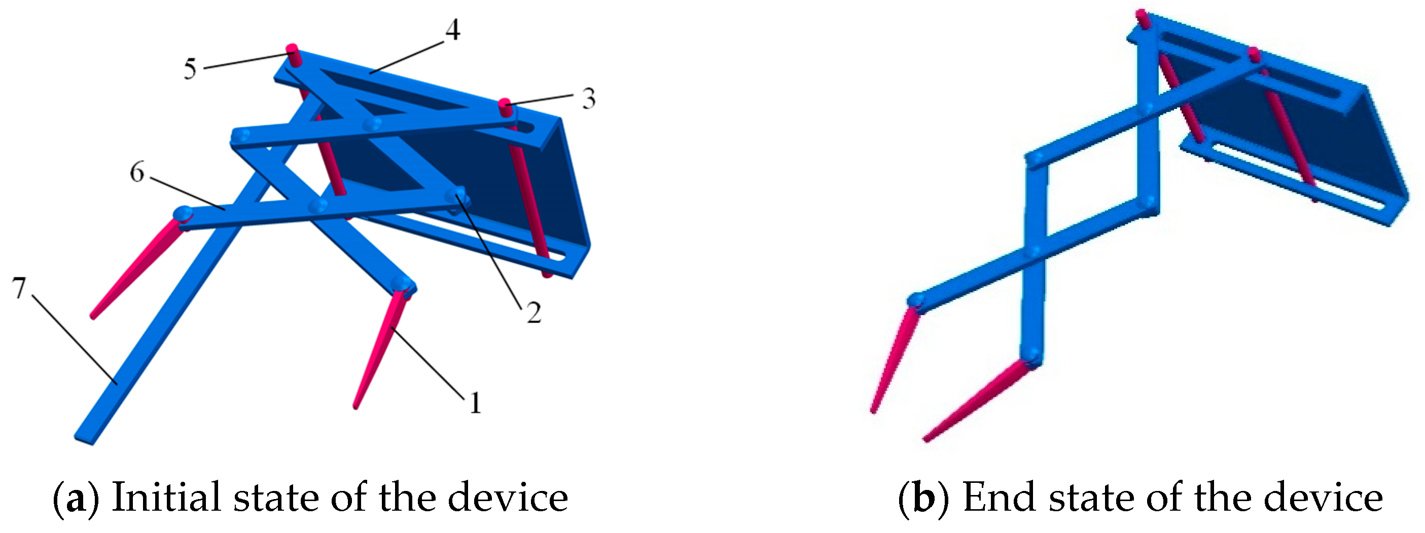
The main function of the device is to remove the seedlings from the plastic tray and transport them to the seedling belts. The stretchable slice-type seedling pick-up device is mainly composed of an upper plate, a fixed rod, a sliding rod, four stretchable slices, two seedling needles, and a withdrawal rod, as shown in Figure 1. A single seedling picking assembly completes the seedling picking. The withdrawal rod is installed on the lower side of the upper plate. When the seedling is taken by the seedling picker, there is adhesion between the root system and the substrate, so that the seedlings at the hole held by the seedling needle do not slip (as shown in Figure 1b). When releasing, it can be quickly separated from the seedling needle under the action of the seedling withdrawal rod (part 7), which is convenient for the device to push the entire seedling into the seedling belt grid.
2.2. Working Principle
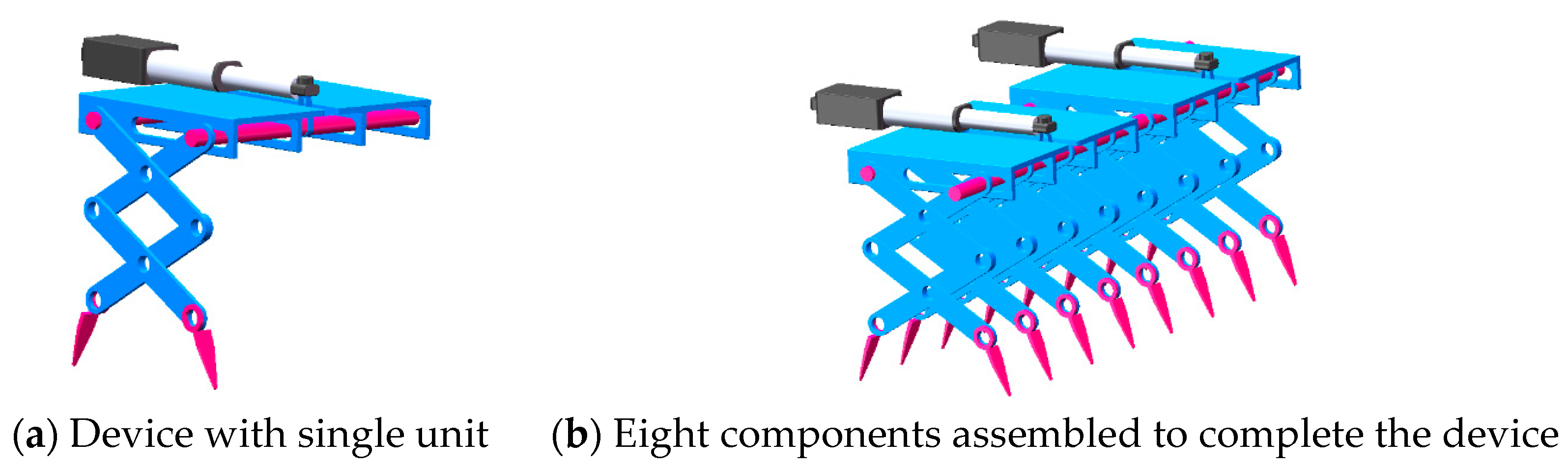
Figure 2a shows a single pick-up assembly. Eight assemblies are gathered together (Figure 2b) to achieve the whole-row seedling picking apparatus. The sliding rod moves in the upper plate chute driven by the micromotor, thus driving the assembly to complete the seedling picking and releasing.
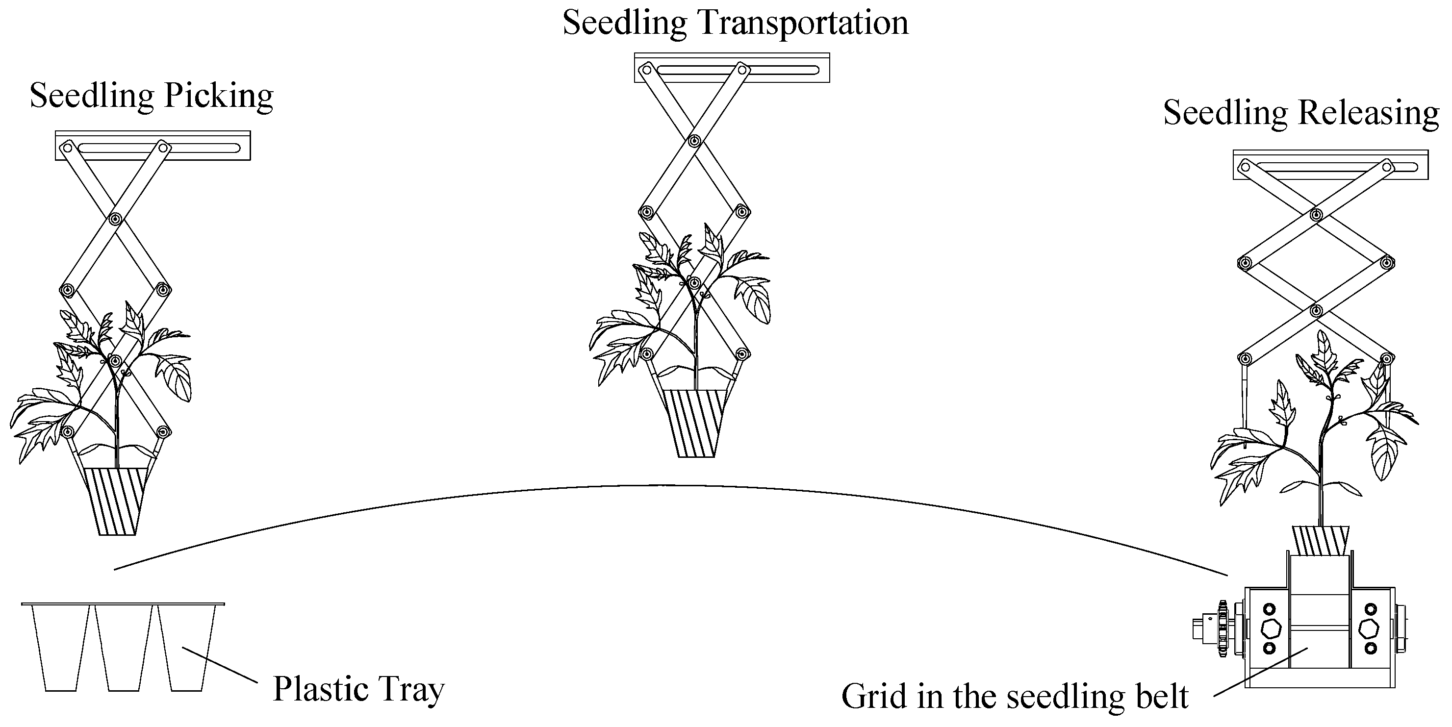
The device is installed at the end of the longitudinal lead screw. Figure 3 is a diagram of the process, which includes the procedures of picking, transporting, and releasing. The working order of the device follows: ① The device is moved back to the preparation position, the electric push rod is pushed out, and the device picks the seedlings. ② The longitudinal lead screw moves upward first, takes the seedlings out of the tray vertically, and the seedlings that are captured move in an arc. This movement is driven by the test bench, which is installed with the horizontal lead screw and vertical lead screw. Each is equipped with a motor and the transport routes are realized. ③ When the component of the device reaches the release position, the sliding rod shrinks back, and the device releases the seedlings under the action of the retreating rod, and falls into the grid of the seedling belt.
3. Seedling Picking Model
3.1. Force Analysis of the Seedlings
A force analysis of the tomato seedlings was carried out to explore the force of the tomato seedlings when they are picked by the device and move upwards to escape from the tray. The factors affecting seedling picking were obtained, and the influence on this effect was analyzed.
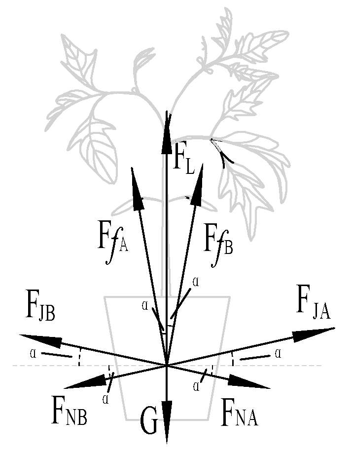
When the device picks the seedlings, the substrate is picked at an angle of α. Figure 4 shows the force analysis when the seedlings are picked. We obtain Equation (1):
In Equation (1), FfA(B) represents static friction force of the needle A (B), FJA(B) is the picking force of needle A (B), FNA(B) signifies the adhesion of needle A (B), G is the gravity of the seedlings, and FL indicates the seedling pulling force.
When picking seedlings, the needles A and B of the device produce a picking force on the substrate, FJA and FJB:
In Equation (2), σ is the anticompression characteristic of the substrate and AJ is the seedling picking area.
At the same time, when the seedlings are pulled out, static friction is generated in the direction parallel to the hole wall, FfA and FfB:
In Equation (3), μ represents the static friction coefficient of the needles.
In addition, when the tomato seedling grows in the tray, the root system is entangled with the substrate and adheres to the inner wall of the hole. The adhesion is represented by FNA and FNB. When the device picks the seedlings and moves upward, it needs to overcome the self-weight G, adhesion FNA(B), picking force FJA(B), and static friction of the seedlings FfA(B), so that the seedlings can be successfully removed.
3.2. Device Motion Model
To explore various motion parameters of the device, the parametric model shown in Figure 5 was established [21], and the rotation center of the fixed rod is the coordinate origin.
Point E is one end point of the sliding rod. When the device operates, the stretchable slice EP moves forward; the angle between the stretchable sheet EP and the x-axis is represented by β. When the device moves, α is the angle between the seedling needles MA and NB and the horizontal line; α can be expressed as:
α = α0 − β
In Equation (4), α0 represents the initial angle of the needles (∠QMA and ∠PNB) and β shows the horizontal angle of stretchable slices (∠OEP and ∠EOQ).
Taking the multiple rods OQMA as the research object, the coordinates of point A can be expressed as:
In Equation (5), lP is the length of the needles and lF is the length of the stretchable slices. When the multiple rods EPNB is used as the research object, the coordinates of point B can be expressed as:
Knowing the displacement equation of the needle, the first derivative of Equation (5) with respect to time t can be calculated, and then the velocity expression at point A can be obtained:
Taking the first derivative of Equation (6) with respect to time t, the velocity expression at point B can be obtained:
Taking the derivative of Equation (4) twice, we obtain
Differentiating Equations (7) and (8) and combining Equations (9) and (10), the accelerations of points A and B can be obtained:
From Newton’s second law, it can be shown that the force of the seedling picker is related to its acceleration. Equations (11) and (12) are the acceleration expressions for points A and B. The influence of various factors cause the change in the needles’ acceleration, which changes the magnitude of the force. These factors include the length of the stretchable slices lF, the length of the needles lP, initial angle of the needles α0, and the horizontal angle of stretchable slices β. Therefore, the picking force can be optimized by changing these parameters.
3.3. Evaluation Indicators
To achieve precise picking of tomato seedlings, the displacement changes of points A and B at the end of the needles were analyzed. This analysis aims to avoid pinching seedlings and damaging the tray. To achieve these goals, the trajectory of the seedlings is optimized.
From Equations (5) and (6), it can be shown that the ordinates of the two points A and B are the same, and then the vertical displacement lDA (lDB) of the two points can be expressed as:
In Equation (14), βt is horizontal angle of the stretchable slices at time t, β0 represents the horizontal angle of the stretchable slice at the initial moment, αt is the horizontal angle of seedling needles at time t, and α0 shows the horizontal angle of the seedling needle at the initial moment.
From Equations (13) and (14), it can be shown that the displacement of the end of the seedling needle is related to the length of the picking needle lP, the length of the stretchable sheet lF, and the movement time t. These three factors can be used as optimization objects to explore the influence of parameter changes on seedling picking.
4. Component Design and Simulation
4.1. Component Design
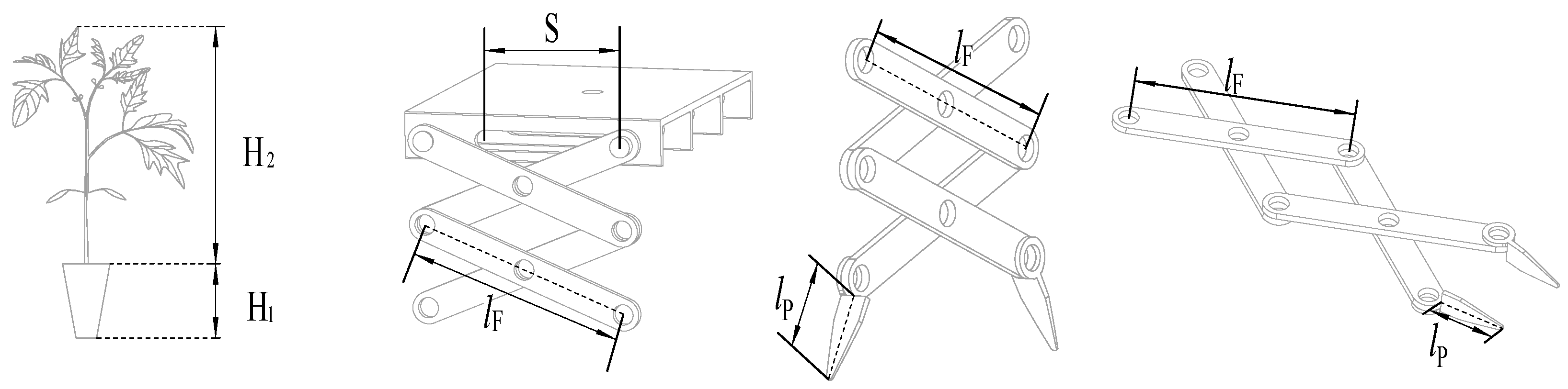
Figure 6 is a schematic diagram showing the height of a whole seedling. When the stretchable slice is moving, the total length of them in the vertical state should be longer than the height of the seedlings. Furthermore, to ensure that the needles do not damage the plastic tray when picking the seedlings, the needle’s length should be less than the depth of the tray. In addition, the length of the stretchable slice should be longer than the distance of the electric push rod. According to these requirements, the parameter range of each component can be obtained:
In Equation (15), H1 is the depth of the tray, H2 represents the average height of the seedlings, and S indicates the electric push rod stroke. According to Equation (15), the minimum length of the stretchable slice is calculated to be 70 mm. The maximum length of pick-up needle lP is 36 mm. The optional maximum distance of the electric push rod S is 70 mm.
We designed the device parts using SOLIDWORKS software, which is a common method adopted by many designers to realize the conception of a product. Four main parts were designed: upper plate, push/fixed rod, stretchable slice, and picking needle. The following figures show the design of the parts from different viewing angles.
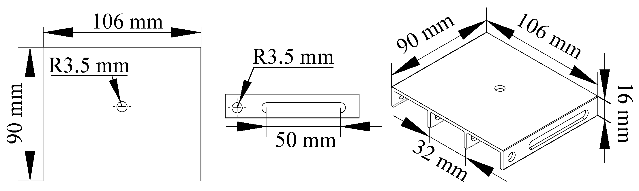
4.1.1. Upper Plate
As shown in Figure 7, the upper plate is a type of rectangular structure with four support slices beneath it, where the push rod can move back and forth at will. The outer dimensions of the upper plate are 90 mm × 100 mm × 16 mm, and the distance between the supporting slices is 32 mm.
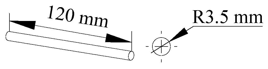
4.1.2. Push/Fixed Rod
The push rod and the fixed rod are installed, respectively, in the chute and round hole of the supporting slice. The push rod can move randomly, which realizes the movement of picking and releasing. The fixed rod can connect with the stretchable slice, which can rotate around it. The two rods are 120 mm in length and 7 mm in diameter. Figure 8 shows their structure.
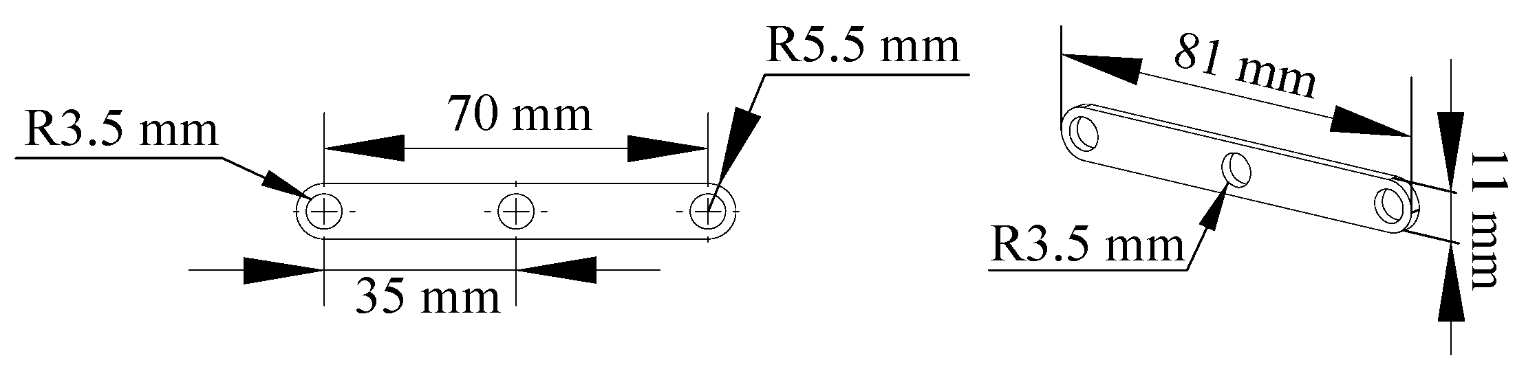
4.1.3. Stretchable Slices
The stretchable slices are the main components of the devices. As shown in Figure 9, the initial length is 70 mm and 11 mm wide. Holes with a radius of 3.5 mm facilitate connection of the device.
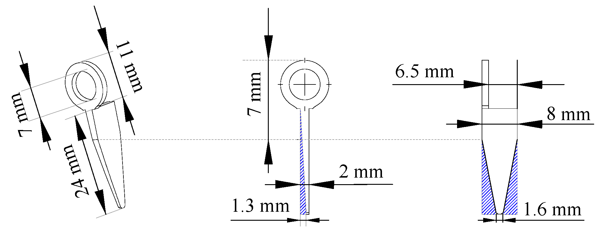
4.1.4. Picking Needle
The picking needle is used to pick the tomato seedlings grown in the plastic tray. As shown in Figure 10, the length and width of this part are 24 and 8 mm, respectively. The spade-shaped structure is more conducive to picking of the seedlings.
4.2. Simulation and Optimization
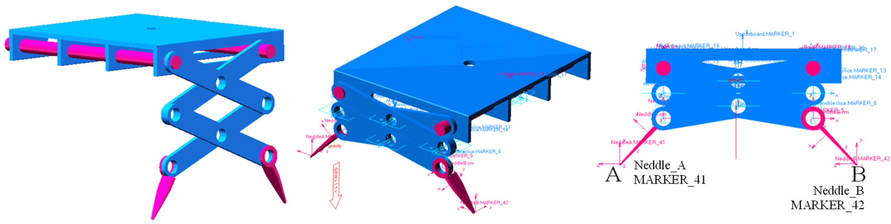
As shown in Figure 11, simulation of the device is undertaken with the procedure carried out in ADAMS [22]. As the world’s most well-known and widely used Multibody Dynamics software, ADAMS improves engineering efficiency and reduces development costs. Engineers can evaluate and manage complex interactions amongdesigns, including motion and structures, to better optimize product designs for performance.
The single factor screening method is used. The first step is to determine the reasonable length of the push rod. On this basis, the phenomenon of reverse crossover of the needles is eliminated. There are two possible options: one is to reduce the length of the pick-up needle lP, and the other method is to increase the length of the expansion piece lF. ADAMS simulations were carried out for the two methods and the distance between the tip of the needle at the end moment analyzed. In this way, the length of the pick-up needle lP and the length of the stretch piece lF are determined.
4.2.1. Push Rod Stroke S
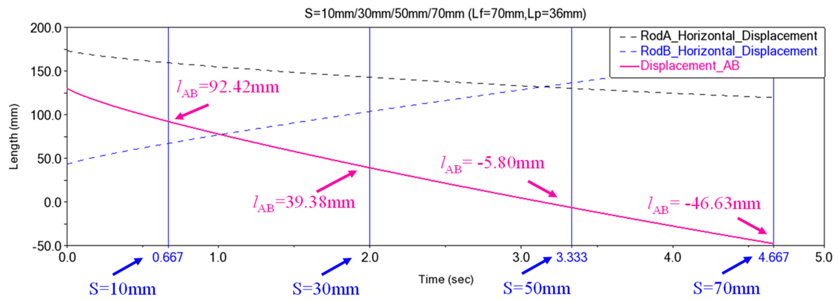
The known maximum stroke of the push rod is 70 mm and its running speed is 15 mm/s; thus, the longest movement time of the putter is 4.667 s. In ADAMS, the exercise time is set at 4.667 s, and the lateral displacement of points A and B at the end of the needles is measured.
Available push-rod strokes are 10, 30, 50, and 70 mm. The corresponding movement times are 0.667, 2, 3.333, and 4.667 s. The results in Figure 12 show that when the exercise time is 0.667 and 2 s, the distance is 92.42 and 39.38 mm, respectively. Both are smaller than 32 mm (the length of the upper side of the hole in the tray), which cannot meet the requirements for taking seedlings. When the movement time is 4.667 s, its distance is −46.63 mm and the seedling needles are reversed, which easily crushes the substrate and damages the plug. Therefore, the stroke of the electric actuator needs to be between 30 and 70 mm, so an electric actuator with a stroke of 50 mm is chosen.
4.2.2. Length of the Needle lP
When the electric push rod has a stroke of 50 mm, the distance between the needles is −5.8 mm. It indicates that the seedling needles cross in the opposite direction, which is not conducive to accurate seedling picking. It is necessary to optimize the length of the pick-up needle lP and the length of the stretchable slices lF to improve the accuracy of picking. Reducing the needle’s length or increasing the length of the stretchable slices are possible solutions. The optimized pick-up needle lengths are 36, 24, and 12 mm. The kinematics simulation is carried out, and the statistical results are shown in Table 1.
It can be seen from the simulation results that reducing the length of the needles can avoid the reverse crossing of the needles at the end of the movement. When the length of the needle is 24 and 12 mm, the distance is −0.185 and 6.305 mm, respectively, which can meet the requirements for picking seedlings. When the length of the needle is 24 mm, there is a larger picking area, which can ensure stable picking. Therefore, a pick-up needle with a length of 24 mm was selected.
4.2.3. Length of the Stretchable Slices lF
When lF is increased, the optimized stretchable sheet lengths are 75, 85, and 95 mm. The kinematics simulation is performed again, and the results are shown in Table 2.
From Table 2, it can be seen that increasing the length of the stretchable slices has no obvious effect on reducing the AB reverse crossing. The reverse crossing is more obvious, so the length of the stretchable slices is the same as the initial value, which is 70 mm.
4.2.4. Displacement and Trajectory of Point A and B
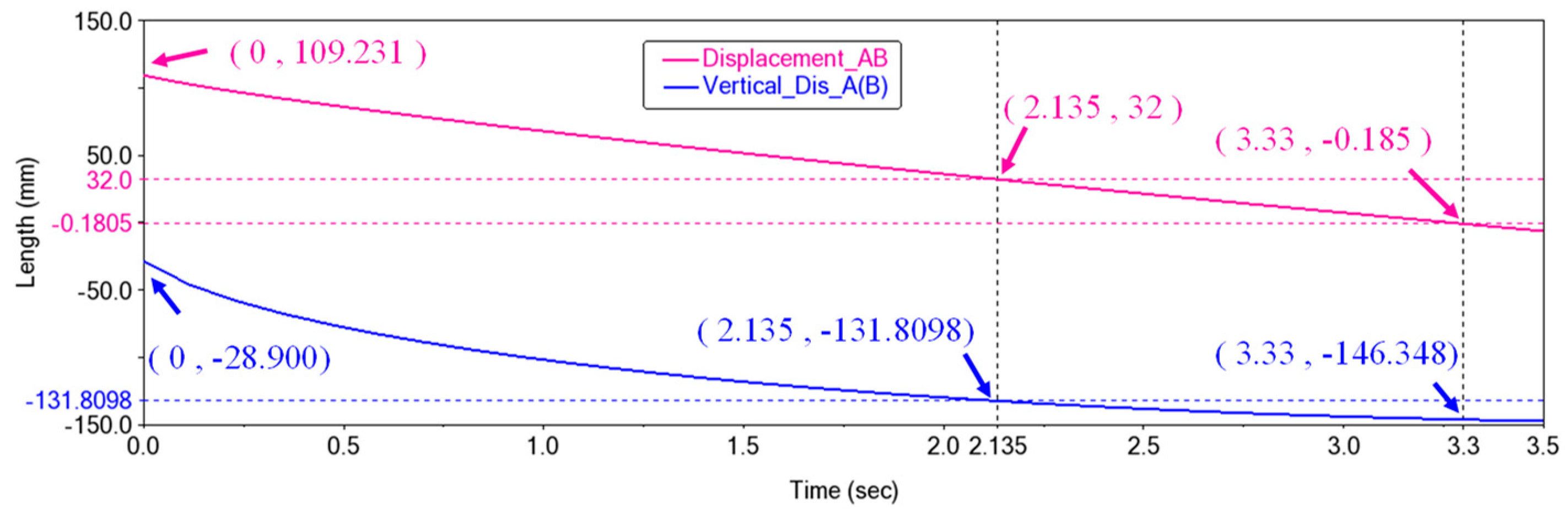
From the simulation described above, it is determined that the stroke S of the push rod is 50 mm, the length of the pick-up needle is 24 mm, and the length of the telescopic piece is 70 mm. The distance and vertical distance between AB can be obtained, and the ideal seedling picking time can also be known.
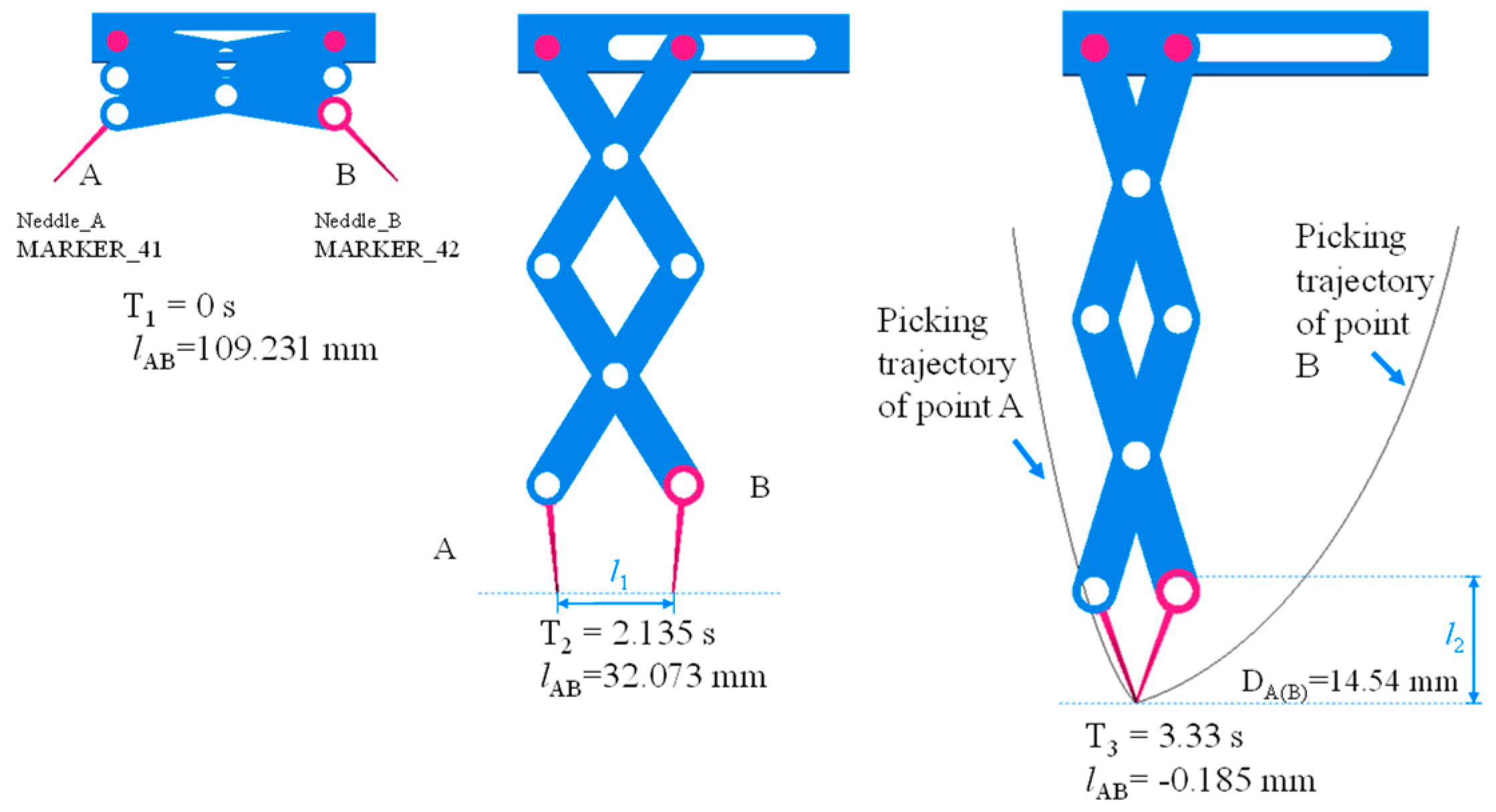
The displacement curve (Figure 13) shows that from 2.135 to 3.33 s the distance at the end is −0.185 mm, and the reverse crossing is not obvious. In this process, the vertical movement distance is 14.55 mm, and the picking point is taken and inserted into one-third of the substrate. This point is in a suitable picking position, which is conducive to stable picking.
Figure 14 illustrates the trajectory curve of the seedling picking. The movement trajectories of points A and B are completely different. This movement characteristic ensures stable picking. This trajectory has better positioning and gripping properties.
4.2.5. Running Speed and Acceleration
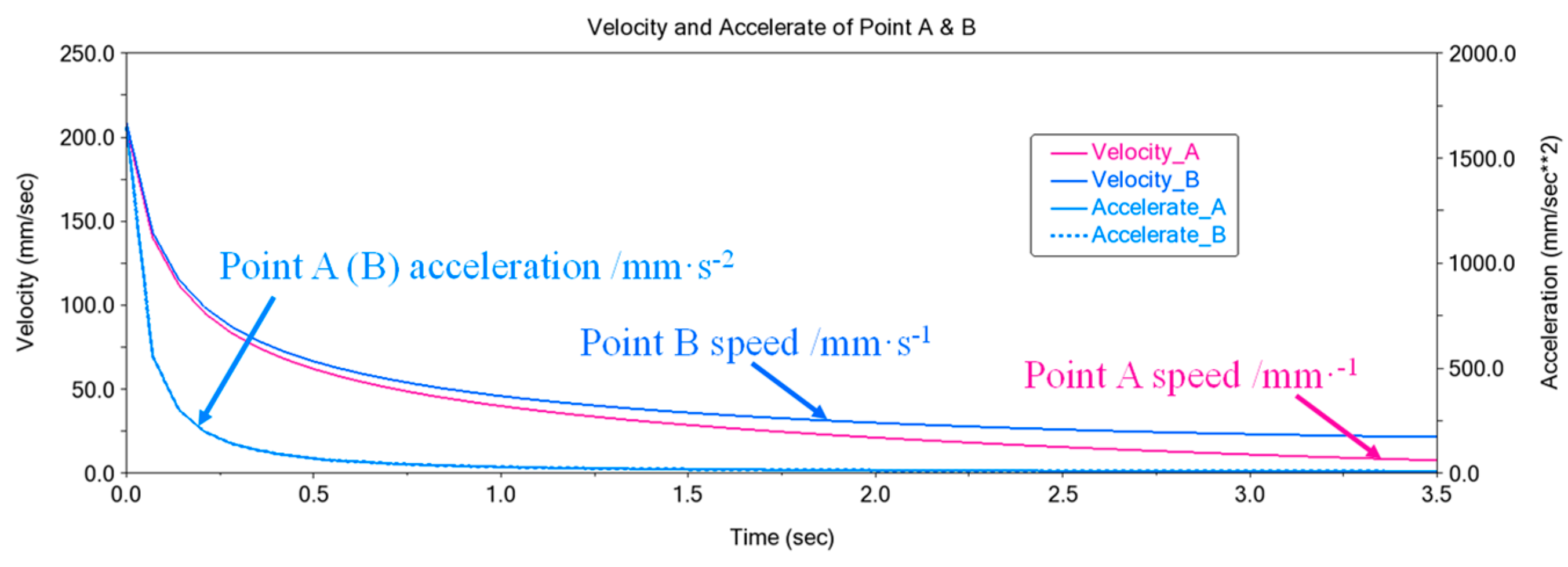
As can be seen from Figure 15, the speed and acceleration show the same changing law: a rapid decrease and a stable decrease afterward. In the initial state, the speed and acceleration of taking seedlings are large, which can quickly reach the substrate plane.
Larger acceleration brings a larger force for taking seedlings, which is more conducive to successful soil breaking. After the soil is broken, the speed and acceleration are reduced to ensure stable picking. The reduction in acceleration reduces the picking force, thereby reducing substrate damage.
5. Test of the Seedling Pick-Up Device
5.1. Trajectory Test
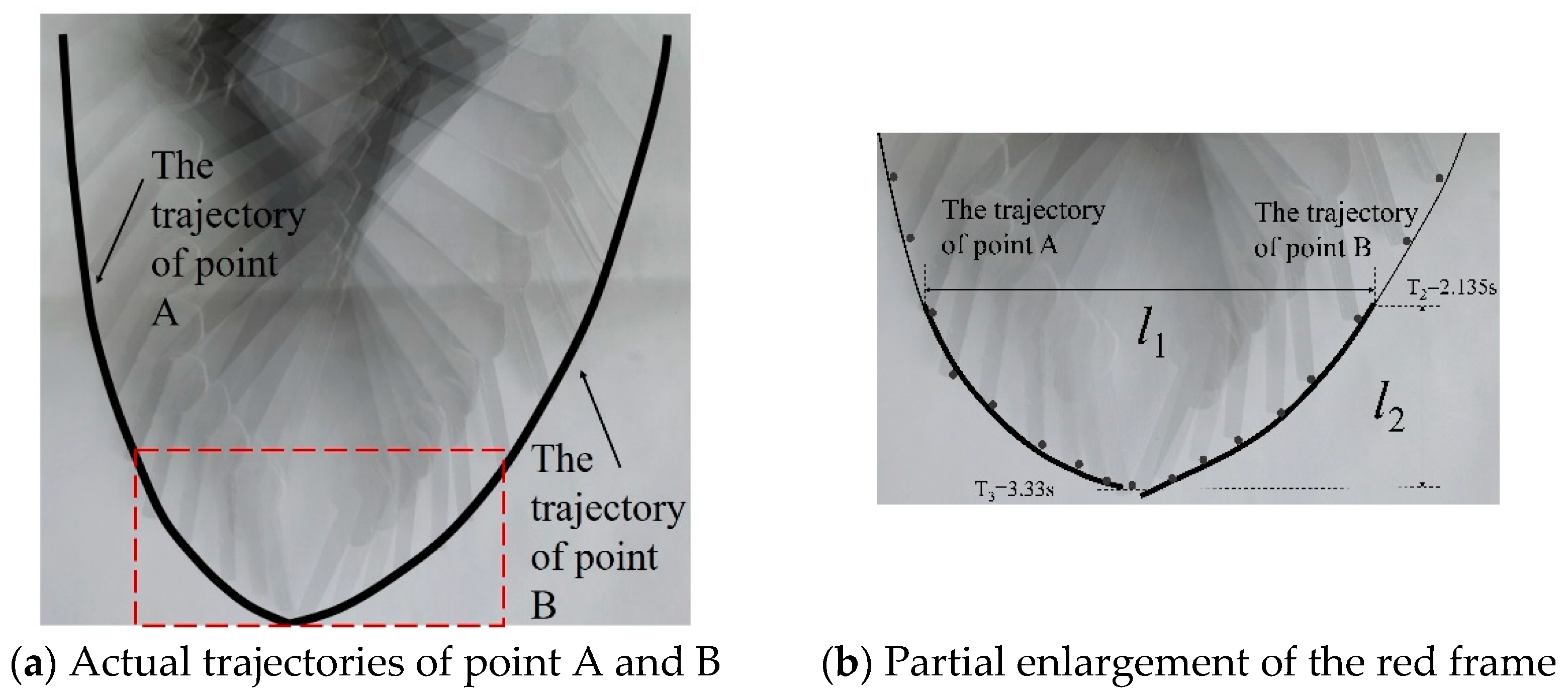
The parts of the seedling device were manufactured (Figure 16) and assembled, and the trajectory test carried out. High-speed photography was performed on the movement process, and the seedling trajectory was obtained after processing. The actual movement trajectory of the device (Figure 17a) is consistent with the simulated trajectory (Figure 14), indicating that the actual working trajectory of the device meets the design requirements. The actual trajectories of point A and B obtained are shown in Figure 18.
In Figure 17b, l1 and l2 of the motion trajectory are measured 10 times; the results are shown in Table 3. The average distance of l1 is 28.30 mm. When the seedling needles reach the substrate plane, the distance is smaller than the hole’s top length W1 (32 mm); this distance makes it easier for the needles to enter the substrate. The vertical movement distance l2 is 13.34 mm, and it is inserted into one-third of the matrix, which is in a better picking position.
5.2. Seedling Picking Test
5.2.1. Evaluation Index
Using seedling success rate Y1, leaf damage rate Y2, and substrate damage rate Y3 as evaluation indicators, a bench test was carried out. The evaluation indicators of the test are defined as follows:
In Equations (16)–(18), n is the total number of tomato seedlings in the whole tray, n1 is the number of seedlings successfully taken from the whole plate of tomato seedlings, n2 represents the number of seedlings in which leaves are broken while successfully taken, m is the weight of a single seedling, and m1 indicates the weight of a single seedling after its release. When the number of damaged leaves of a single seedling exceeds three, the tomato plug seedling is determined to be damaged.
5.2.2. Test Design
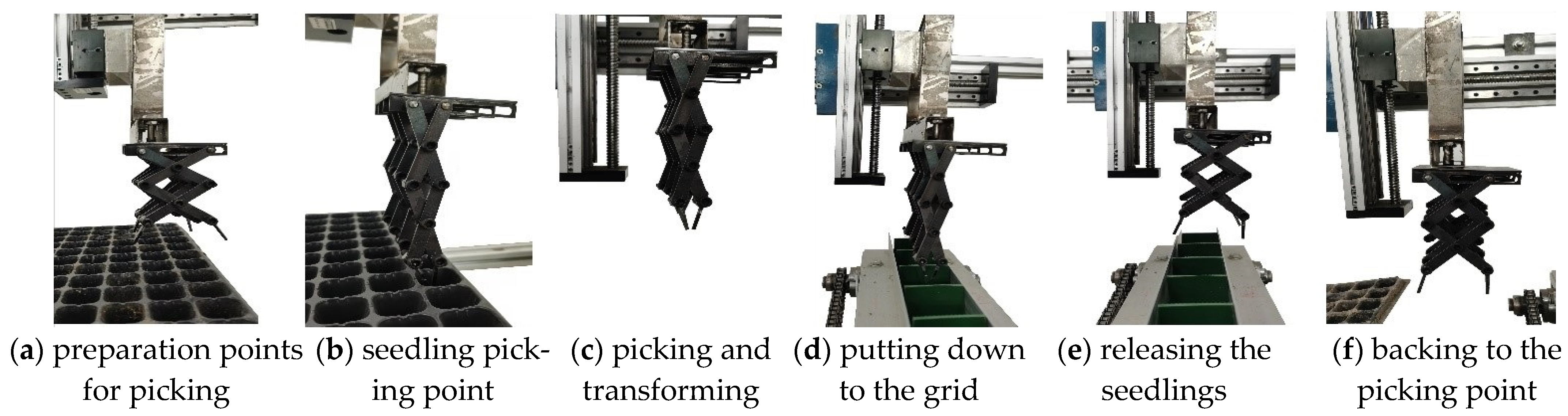
The experiment was carried out in the Precision Agriculture Laboratory of Shihezi University. Seedlings with an age 30~50 d were selected and the moisture content was 35.41%~65.21%. The process of picking and releasing seedlings is shown in Figure 18. The device picks the seedlings on the left side, moves to the top of the belt on the right side, and returns to the seedling initial position. It takes 8.228 s for the device to complete the process, including soil breaking (3.33 s), upward pulling (1 s), conveying (1.831 s), release (1 s), and return (1.067 s). Eight seedlings are taken during each working cycle, and 58 seedlings are taken in one minute.
5.2.3. Analysis of Test Results
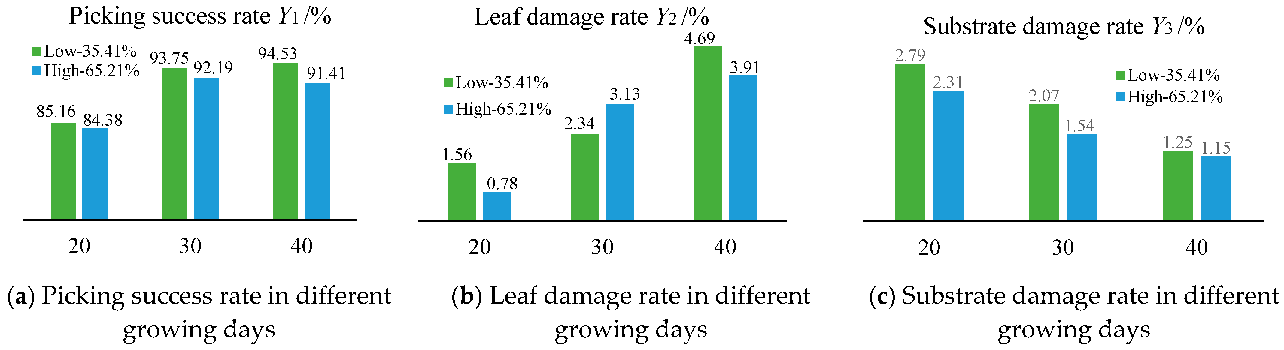
The effect of a different number of growing days on each evaluation index was analyzed; the data are shown in Figure 19. Figure 19a shows that the seedlings with a growth age of 30 to 40 d and moisture content of 35.41% have the highest success rate. Because the root system of the seedlings by this time is developed, the method is conducive to picking. Figure 19b shows that when the growth days increase, the leaf damage rate also increases. There is no significant relationship between leaf damage rate and moisture content. The longer the seedlings, the lusher the leaves, and they are easily damaged by the pick-up device. Figure 19c shows that the substrate damage rate decreases with the increase in seedling age, and the substrate damage rate of the seedlings with a moisture content of 65.21% is lower. The seedlings with a moisture content of 65.21% have a low breakage rate. The root system developed has a stronger entanglement effect on the substrate. Increasing the moisture content increases the adhesion of the substrate, resulting in less scattering during work.
The pick-up device has a good effect on the seedlings that have grown for 30 days and have a moisture content 65.21%. At this time, the success rate of seedling picking was 92.19%, the leaf damage rate was 3.13%, and the substrate damage rate was 1.54%.
6. Conclusions
According to the working requirements of a transplanting machine for picking seedlings in a row, we designed a stretchable slice-type seedling picker. It is mainly composed of stretchable slices, moving rods, fixed rods, and other components. Key components were designed according to seedling height and tray size. A model of the device’s movement was established and evaluation indexes proposed.
ADAMS was used to carry out kinematic simulation of the device, and we used the method of distance screening to optimize the stroke of the electric push rod, the length of the pick-up needle, and the length of the stretchable slices. We obtained better parameters for the components, and analyzed their displacement, velocity, and acceleration. The results verify that the seedling picker has the advantages of high seedling picking accuracy and minor damage to the substrate.
The parts of the device were manufactured and assembled, and a trajectory experiment completed. Our experimental results show that the actual trajectory is consistent with the simulated trajectory. The seedling picking test showed that when the seedlings were grown for 30 days and the moisture content was 65.21%, the success rate of seedling picking was 92.19%, the leaf damage rate was 3.13%, and the substrate damage rate was 1.54%.
Author Contributions
Conceptualization, L.R. and B.Z.; methodology, L.R.; software, B.Z.; validation, W.C., W.S. and M.Z.; formal analysis, investigation and resources, L.R.; data curation, B.Z.; writing—original draft preparation, L.R.; writing—review and editing, B.Z.; project administration and funding acquisition, L.R. All authors have read and agreed to the published version of the manuscript.
Funding
This research was funded by the National Natural Science Foundation of China, grant number 51765059; Shihezi University High-level Talent Project, grant number RCZK2021B17; and Shihezi University self-supported scientific research projects, grant number ZZZ202105.
Institutional Review Board Statement
Not applicable.
Informed Consent Statement
Not applicable.
Data Availability Statement
All relevant data presented in the article are stored according to institutional requirements and, as such, are not available online. However, all data used in this manuscript can be made available upon request to the authors.
Conflicts of Interest
The authors declare no conflict of interest.
References
- Zhu, M.; Guan, Z.; Wu, F. An Overview of the US Tomato Industry; Florida Tomato Institute Program: Immokalee, FL, USA, 2013. [Google Scholar]
- Costa, J.M.; Heuvelink, E. The global tomato industry. In Tomatoes, 2nd ed.; CABI: Boston, MA, USA, 2018; pp. 1–26. [Google Scholar]
- Zhao, D.; Wang, Z. Improving Yield and Quality of Processing Tomato (Lycopersicon esculentum Miller) Using Alternate Partial Root-Zone Drip Irrigation in Arid Northwest China. Water 2019, 11, 1503. [Google Scholar] [CrossRef] [Green Version]
- Kumar, G.P.; Raheman, H. Vegetable transplanters for use in developing countries—A review. Int. J. Veg. Sci. 2008, 14, 232–255. [Google Scholar] [CrossRef]
- Choi, W.C.; Kim, D.C.; Ryu, I.H.; Kim, K.U. Development of a seedling pick–up device for vegetable transplanters. Trans. ASAE 2002, 45, 13. [Google Scholar]
- Ji, J.; Cheng, Q.; Jin, X.; Zhang, Z.; Xie, X.; Li, M. Design and test of 2ZLX-2 transplanting machine for oil peony. Int. J. Agric. Biol. Eng. 2020, 13, 61–69. [Google Scholar] [CrossRef]
- Han, L.; Mao, H.; Hu, J.; Tian, K. Development of a doorframe-typed swinging seedling pick-up device for automatic field transplantation. Span. J. Agric. Res. 2015, 13, 13. [Google Scholar] [CrossRef] [Green Version]
- Yung, I.; Maccarana, Y.; Maroni, G.; Previdi, F. Partially structured robotic picking for automation of tomato transplantation. In Proceedings of the 2019 IEEE International Conference on Mechatronics, Ilmenau, Germany, 18–20 March 2019. [Google Scholar]
- Yin, D.; Wang, J.; Zhou, M. Optimal Design and Experiment of Vegetable Potted Seedlings Pick-up Mechanism for Exploring and Picking-Pushing Plugs. Trans. Chin. Soc. Agric. Mach. 2019, 50, 64–71. [Google Scholar]
- Ye, B.; Tang, T.; Yu, G. Dynamic analysis of rotary seedling pick-up mechanism of vegetable transplanting machine with counterweight. Trans. Chin. Soc. Agric. Mach. 2019, 50, 117–122. [Google Scholar]
- Wang, L.; Sun, L.; Xu, Y. Design Method of Transplanting Mechanism of Planetary Gear Train Based on Spatial Trajectory. Trans. Chin. Soc. Agric. Mach. 2021, 52, 51–59. [Google Scholar]
- Jiang, Z.; Jiang, H.; Tong, J. Optimal design of end-effector on automatic plug seedling transplanter. J. Zhejiang Univ. 2017, 51, 1119–1125. [Google Scholar]
- Han, B.; Shen, D.; Guo, C. Design and Experiment of Adjustable End-effector of Cabbage Seedlings. Trans. Chin. Soc. Agric. Mach. 2019, 50, 111–120. [Google Scholar]
- Xie, S.; Yang, S.; Liu, J. Development of the seedling taking and throwing device with oblique insertion and plug clipping for vegetable transplanters. Trans. Chin. Soc. Agric. Eng. 2020, 36, 1–10. [Google Scholar]
- Wang, C.; Liu, C.; Li, Y. Design and Experiment of Pneumatic Punching High-speed Seedling Picking Device for Vegetable Transplanter. Trans. Chin. Soc. Agric. Mach. 2021, 52, 35–43. [Google Scholar]
- Mao, H.; Han, L.; Zhao, H. Design of root lump loosening mechanism using air jets to eject vegetable plug seedlings. Trans. Chin. Soc. Agric. Eng. 2019, 35, 37–45. [Google Scholar]
- Yuan, T.; Wang, D.; Wen, Y. Design and experiment of seedlings unloading mechanism based on methods of air-blowing and vibration for vegetable transplanter. Trans. Chin. Soc. Agric. Mach. 2019, 50, 80–87. [Google Scholar]
- Jin, X. Research on Automatic Transplanting Technology and Device for Vegetable Plug Seedling; China Agriculture University: Beijing, China, 2014. [Google Scholar]
- Zhang, W. The Design and Optimization of Transplanting End-Effector on TRIZ; Nanjing Agricultural University: Nanjing, China, 2015. [Google Scholar]
- Wang, M. Design and Experimental Research on Critical Components of Auto Transplanter with Combined Tray; China Agriculture University: Beijing, China, 2017. [Google Scholar]
- Petrescu, F.I.T. Advanced Dynamics Processes Applied to an Articulated Robot. Processes 2022, 10, 640. [Google Scholar] [CrossRef]
- Hroncová, D.; Binda, M.; Šarga, P.; Kičák, F. Kinematical analysis of crank slider mechanism using MSC Adams/View. Procedia Eng. 2012, 48, 213–222. [Google Scholar] [CrossRef]
Figure 1.
Structure diagram of the seedling pick-up device: 1, needle; 2, pins; 3, sliding rod; 4, upper plate; 5, fixed rod; 6, stretchable slice; 7, withdraw rod.
Figure 1.
Structure diagram of the seedling pick-up device: 1, needle; 2, pins; 3, sliding rod; 4, upper plate; 5, fixed rod; 6, stretchable slice; 7, withdraw rod.

Figure 2.
Stretchable unit and overall assembly.

Figure 3.
Procedure diagram of seedling picking.

Figure 4.
Force analysis of a seedling.

Figure 5.
Structure diagram of the pick-up device. OQ, EP, PN, and QM are stretchable slices, MA and NB are needles, β is the angle between stretchable slice and horizontal plane, α0 is the initial installation angle of seedling needles and stretchable slices, and α is the angle between the seedling needle and the horizontal plane.

Figure 6.
Schematic diagram of seedling height and the size of the part.

Figure 7.
Drawing of the upper board structure.

Figure 8.
Drawing of pushing rod structure.

Figure 9.
Drawing of stretchable slices structure.

Figure 10.
Drawing of picking slices structure. The blue section line in the figure is the excised part.
Figure 10.
Drawing of picking slices structure. The blue section line in the figure is the excised part.

Figure 11.
Simulation in ADAMS.

Figure 12.
The change rule of the displacement AB in different push rod distance.

Figure 13.
Displacement of AB and the distance of the vertical motion.

Figure 14.
Trajectory diagram simulated by ADAMS.

Figure 15.
Velocity and acceleration at points A and B.

Figure 16.
Components of the pick-up device.

Figure 17.
Movement trajectory diagram of seedling picking. At T2 = 2.135 s, the device starts to take seedlings, and at T3 = 3.33 s, the seedlings are picked; l1 is the distance when the needle touches the substrate plane and l2 is the vertical displacement of the movement.
Figure 17.
Movement trajectory diagram of seedling picking. At T2 = 2.135 s, the device starts to take seedlings, and at T3 = 3.33 s, the seedlings are picked; l1 is the distance when the needle touches the substrate plane and l2 is the vertical displacement of the movement.

Figure 18.
Process of seedling picking and releasing.

Figure 19.
Results of seedling picking after 20, 30, and 40 growing days.


Table 1.
Motion distance of the point under different needle lengths.
| Length of the Needle lP/mm | Distance between AB at the End Time/mm | Distance of Vertical Movement of Point A or B/mm |
|---|---|---|
| 36 | −10.243 | 116.008 |
| 24 | −0.185 | 117.449 |
| 12 | 6.305 | 114.085 |
Table 2.
Motion distance of the point under different lengths of flexible slices.
| Length of the Stretchable Slices lF/mm | Distance between AB at the End Time/mm | Distance of Vertical Movement of Point A or B/mm |
|---|---|---|
| 75 | −1.700 | 89.437 |
| 85 | −2.549 | 65.950 |
| 95 | −4.743 | 53.675 |
Table 3.
Results of trajectory measurement.
| No. | 1 | 2 | 3 | 4 | 5 | 6 | 7 | 8 | 9 | 10 | Average |
|---|---|---|---|---|---|---|---|---|---|---|---|
| l1 | 28.6 | 28.7 | 27.2 | 26.6 | 29.2 | 29.8 | 28.5 | 28.3 | 28.8 | 27.3 | 28.3 |
| l2 | 12.8 | 13.5 | 14.5 | 12.7 | 12.9 | 12.5 | 13.8 | 12.5 | 13.8 | 14.2 | 13.34 |
Table 4.
Results of the picking test.
| No. | Factors | Evaluation Index | ||||
|---|---|---|---|---|---|---|
| Growing Days/d | Moisture Content/% | Seedling Picking Success Rate/% | Leaf Damage Rate/% | Substrate Damage Rate/% | ||
| 1 | 20 | 35.41 | 85.16 | 1.56 | 2.79 | |
| 2 | 20 | 65.21 | 84.38 | 0.78 | 2.31 | |
| 3 | 30 | 35.41 | 93.75 | 2.34 | 2.07 | |
| 4 | 30 | 65.21 | 92.19 | 3.13 | 1.54 | |
| 5 | 40 | 35.41 | 94.53 | 4.69 | 1.25 | |
| 6 | 40 | 65.21 | 91.41 | 3.91 | 1.15 | |
Publisher’s Note: MDPI stays neutral with regard to jurisdictional claims in published maps and institutional affiliations. |
© 2022 by the authors. Licensee MDPI, Basel, Switzerland. This article is an open access article distributed under the terms and conditions of the Creative Commons Attribution (CC BY) license (https://creativecommons.org/licenses/by/4.0/).
Share and Cite
MDPI and ACS Style
Ren, L.; Zhao, B.; Cao, W.; Song, W.; Zhao, M. Design of Stretchable Style Pick-Up Device for Tomato Seedling Transplanters. Agriculture 2022, 12, 707. https://0-doi-org.brum.beds.ac.uk/10.3390/agriculture12050707
AMA Style
Ren L, Zhao B, Cao W, Song W, Zhao M. Design of Stretchable Style Pick-Up Device for Tomato Seedling Transplanters. Agriculture. 2022; 12(5):707. https://0-doi-org.brum.beds.ac.uk/10.3390/agriculture12050707
Chicago/Turabian StyleRen, Ling, Bindong Zhao, Weibin Cao, Wenbin Song, and Ming Zhao. 2022. "Design of Stretchable Style Pick-Up Device for Tomato Seedling Transplanters" Agriculture 12, no. 5: 707. https://0-doi-org.brum.beds.ac.uk/10.3390/agriculture12050707
Note that from the first issue of 2016, this journal uses article numbers instead of page numbers. See further details here.