Study on Parameterization of Vortex-Induced Vibration Energy Harvester in Agricultural Environment

1
School of Engineering, Jiangxi Agricultural University, Nanchang 330045, China
2
Research Center of Animal Husbandry Facility Technology Exploitation, Nanchang 330045, China
*
Author to whom correspondence should be addressed.
AgriEngineering 2020, 2(4), 511-522; https://0-doi-org.brum.beds.ac.uk/10.3390/agriengineering2040034
Submission received: 21 August 2020
/
Revised: 27 September 2020
/
Accepted: 30 September 2020
/
Published: 2 October 2020
Abstract
:In many special agricultural environments, many wireless sensors have a problem of power supply selection. Energy harvesting in the agricultural environment based on vortex-induced vibration (VIV) has the potential to solve the problem. In this paper, an energy harvester based on the VIV is designed in an agricultural environment. Relevant parameters of the harvester are studied with wind tunnel experiment to improve the efficiency of energy conversation. The results show that: (i) For large mass ratio, , and the same mass ratio , the smaller the damping ratio , the larger the normalized amplitude , the larger the maximum efficiency of VIV energy harvesting; (ii) , and under a certain range of Reynolds numbers, the smaller the mass-damping parameter , the larger the normalized amplitude , the larger the maximum and average efficiency of VIV energy harvesting. (iii) , the larger the mass ratio , the larger the range of resonance; the normalized frequency , the stable VIV locked state appears. The research results can provide references for the design of VIV energy harvesters in agricultural environments.
1. Introduction
Within the rapid development of the Internet of Things, big data, artificial intelligence, etc., and wireless sensor networks are widely used in military, environmental monitoring, intelligent agriculture, and other fields [1,2]. Much attention has been drawn to a problem of power supply of wireless sensors. At present, the power supply methods of wireless sensors include chemical batteries, rechargeable batteries, and solar batteries, mainly depending on chemical batteries. However, it is inconvenient to replace the chemical battery for some places. Therefore, environmental energy harvesting is an efficient way to solve the problem of power supply of wireless sensor in recent years, providing new power supply options for wireless sensors. Discussion regarding vibrational energy harvesting around wireless sensor networks have dominated research at home and abroad. Utilization of Vortex-Induced Vibration (VIV) of an elastically supported bluff body convert mechanical energy into electricity. A well-known phenomenon is the alternate shedding of vortices when the fluid pass through a bluff body and the associated unsteady aerodynamic forces acting on the bluff body [3]. When these vortices fall off at a frequency close to the natural frequency of the bluff body, lock-in or synchronization occurs, and resonant lateral vibration occurs [4,5,6,7,8,9,10]. Therefore, using the VIV of an elastically supported bluff body to convert energy has broad application prospects, but the key technology is not mature.
The fluid flow rate is uniform and low which preconditions to trigger VIV. The wind and water characteristics are measured and analyzed in some places of agriculture engineering, such as ventilation system of piggery houses and greenhouses, open channel, pipeline system of sewage treatment, and so on. The fluid velocity in these places is uniform and low, and they have powerful conditions for triggering VIV, so this makes the research of agricultural VIV energy harvesting potentially achievable (Generally, the natural frequency of the energy harvesting structure is low, the shedding frequency of the fluid at low flow rate is also low, which can resonate well. And the stable flow velocity makes the VIV have a stable amplitude). To effectively improve agricultural informatization and improve the level of production management, wireless sensor network as an efficient, real-time information collection system has been applied to facility agricultural production [11,12]. However, in a specific agricultural production environment, the power supply energy of wireless sensors (the network node) will not be able to rely on traditional power sources. The stable working power of the wireless sensor is usually between 2 mW and 3 mW, the current research results of related VIV energy harvesters show that when the harvester is in resonance, the maximum output power can fully meet the power of the wireless sensor for stable operation [13]. This will make the energy harvester a new choice for wireless sensor network nodes to supply power, especially in the agricultural environment where it is impossible or inconvenient to replace the traditional power source-battery, such as sewage treatment water quality monitoring [14], farmland water saving irrigation monitoring, agricultural greenhouse environment monitoring, and agricultural environment monitoring of breeding houses [2] in extreme cold areas (Traditional batteries will not work properly in extremely cold areas).
In order to better design the VIV energy harvester, the current related VIV literature has been carefully read. Much of the early related basic research on VIV has been reviewed by Bearman [15], Sarkkaya [16], and Williamson and Govardhan [17]. In recent years, many scholars have conducted research on this issue. Khalak and Williamson studied the influence of mass-damping parameter on the amplitude and lock-in interval, and the normalized amplitude expression is derived from the VIV equation [18,19]; Allen and Smith et al. [20] developed an eel-like energy harvester, and used the eel structure to collect the kinetic energy in the water flow; Bernitsas et al. [21] have developed a device called VIVACE (Vortex Induced Vibration Aquatic Clean Energy), which uses the VIV cylinder mounted on the spring which is used to collect the water flow energy, and also studies how to effectively collect energy from the vibration phenomenon caused by the flow [22,23]; Antonio Barrero-Gilet al. [24] conducted a numerical analysis on the energy harvesting of a cylinder mounted on a spring; A.PERELLI et al. [25] used the principle of VIV to design an energy harvester and perform performance analysis; Xiaotong Gao et al. [26] proposed a new type of fluid energy harvesting device. The fluid flows through a fixed cylinder to generate eddy currents, which makes the flexible piezoelectric sheet vibrate to generate electricity. Luo Zhumei et al. [27,28] studied the parameters affecting the energy acquisition from VIV in ocean currents and analyzed the influence of each parameter on the energy acquisition efficiency. However, the above research mainly focuses on the collection of marine vibration energy, while the collection of agricultural environment vibration energy is less involved. The above-mentioned VIV research is mainly in the field of ocean engineering. The VIV energy harvesting system studied is a system composed of a cylinder connected to a spring, which provides a certain reference for the design of the energy harvesting device in this article.
An energy harvester based on the VIV in agricultural environments is designed, the energy harvesting system is a cantilever beam connected by a cylinder. The stiffness and damping ratio of the system are mainly derived from the cantilever beam, the cantilever beam has a certain influence on the entire flow field. Whether the relevant conclusions of the literatures are suitable for the VIV of the energy harvester is worth considering. So, the relevant parameters of the harvester are studied to improve efficiency of energy conversation. It includes the damping ratio , the mass-damping parameter (the mass ratio is the ratio of the average density of the cylinder to the density of the surrounding fluid). The research aims to obtain the maximum efficiency of energy conversion under specific mechanical parameters. We begin in Section 2, introducing a simple mathematical model of VIV of a cantilever beam connected by cylinders, which helps to introduce an energy conversion factor. Next, we introduced the experimental equipment and experimental model data in detail in Section 3. Based on the mathematical model established in Section 2, a parametric study is carried out in Section 4, revealing the role of the effect of each parameter on the model conversion efficiency. Finally, some conclusions are drawn in Section 5.
2. Mathematical Model
2.1. Mathematical Model of VIV of Cylinder
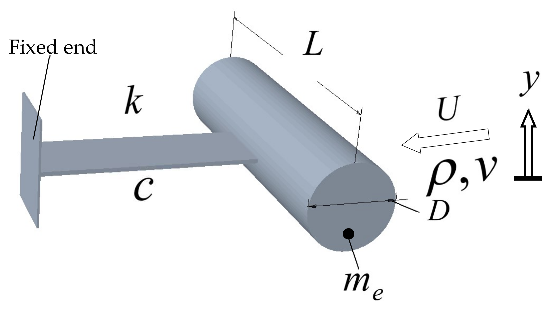
As shown in Figure 1. Here, we will consider a simplified situation that is under the action of the inflow, the cantilever mounted cylinder is prone to VIV oscillations in the transverse y. In fact, the cylinder does not move completely laterally, which may affect the measurement of its amplitude value, but this effect is minimal. To simplify the system and ignore this effect.
The internal dissipation damping ratio of the energy harvesting system can be expressed as
where is the natural frequency and is the mechanical damping coefficient.
The mass per unit length of the cantilever beam connected to the cylinder system is , the transversal displacement of the cylinder is determined by the interaction of inertial force, damping force, stiffness, and lift force, which can be expressed as
where is the first-order derivative with respect to physical time , is the second-order derivative with respect to physical time , and is the vibration circle frequency.
Within the resonance range, the lift force of each unit can be approximately expressed as
where is fluid density, is the flow rate, is the diameter of the cylinder, is the lift coefficient, is the vibration frequency, and is the phase angle between the lift and the displacement of the cylinder [10].
Substituting Equation (3) in Equation (2), considering (based on experimental evidences) a steady state of harmonic oscillation , and normalized amplitude , normalized frequency , and the reduced velocity , it can be obtained as:
For large mass ratio,, from Equation (5) one can see that (the experiments show that , ). Then, one may deduce that, in this case, the normalized amplitude is a function of the product of the combined mass-damping parameter and the reduced velocity . For , however, Equations (4) and (5) are coupled, and hence should be a function of two independent parameters and , as well as .
2.2. Efficiency
The transfer of energy can be regarded as the power done by the fluid per unit length in a vibration period . Conversion efficiency can be defined as the ratio of the power obtained from the fluid per unit length to the total power of the fluid per unit length, namely
The total power per unit length of fluid can be expressed as . Where is the power obtained by the cylinder per unit length from the fluid in each vibration period , namely
In the lock-in region, the state of sinusoidal vibration is steady. By the simultaneous Equations (3), (6), and (7), conversion efficiency can be expressed by the normalized amplitude , the reduced velocity , the normalized frequency , and the fluid force excitation coefficient , which is
We can see from Equation (8) that under certain mechanical parameters, the conversion efficiency of VIV is directly related to the fluid force excitation coefficient , the normalized amplitude , and the reduced velocity
3. Experimental Equipment
3.1. Annular Wind Tunnel
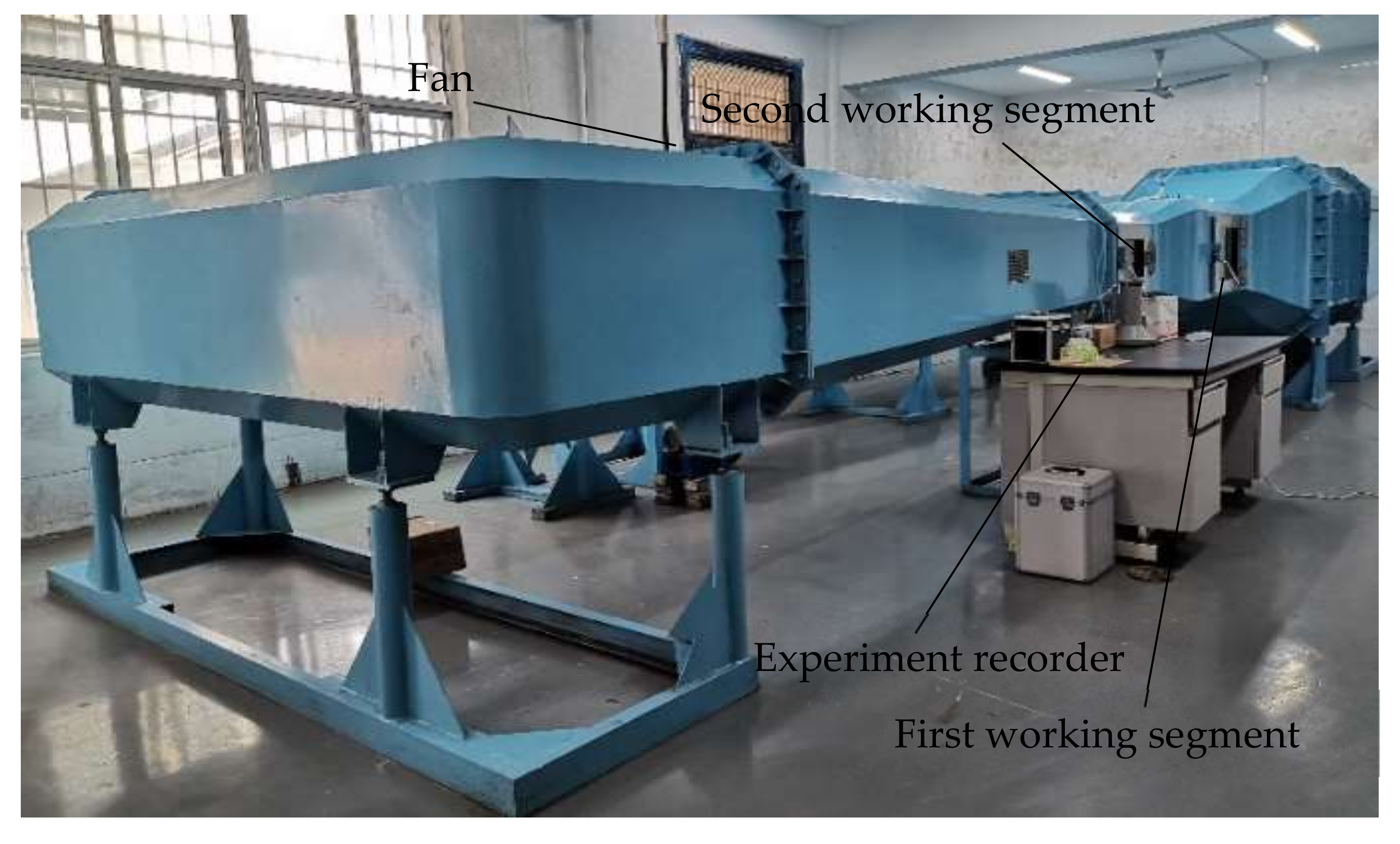
The experiment was carried out in an annular multifunctional wind tunnel, as shown in Figure 2. The overall size of the wind tunnel is 9.9 m × 3.5 m × 2.0 m. The airflow generated by the fan passes through the return section, corner section, stable section, contraction section, and the first working section, the second working section, and the diffuser section circulate in motion. The flow velocity of the working section ranges from 0.2 to 40 m/s. The relative standard deviation of flow velocity uniformity is ≤1% in the wind tunnel working area, and the relative deviation of flow velocity stability is ≤0.5% in the wind tunnel working area. The flow field in the working area is stable, basically free from external interference, and does not have high requirements for the experimental environment.
3.2. Experimental Model and Experimental System
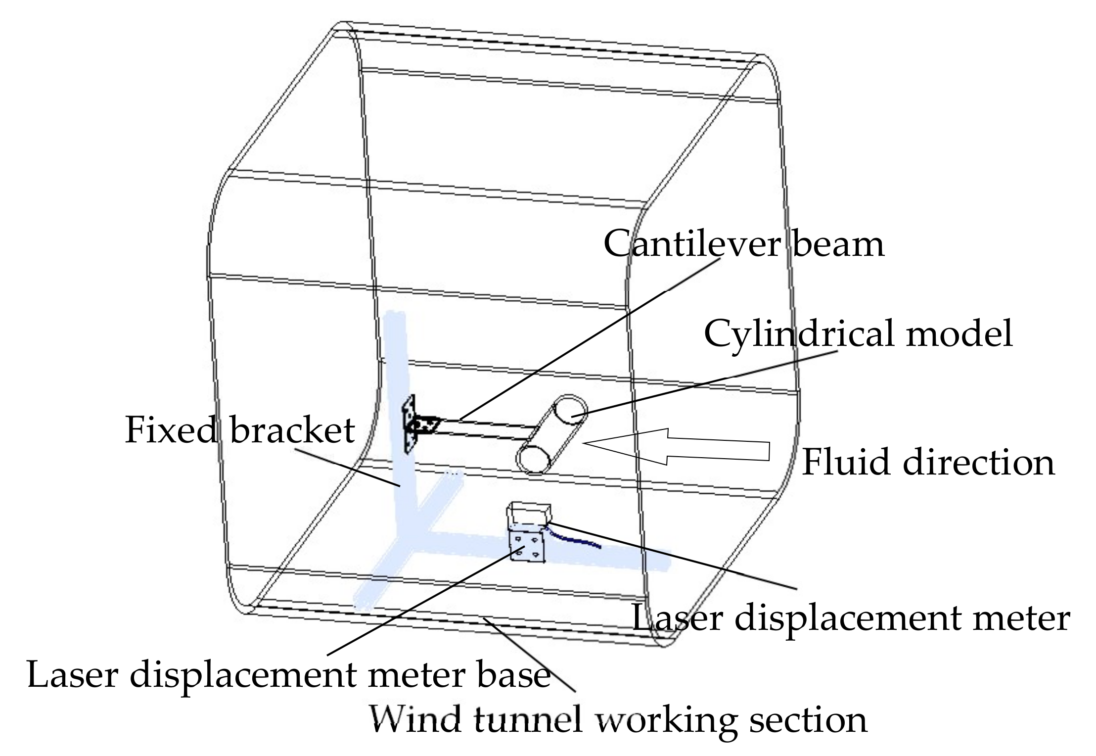
The experimental model is shown in Figure 3. The experimental model includes a fixed bracket, a cantilever beam, and a cylindrical model. The cantilever beam is laser-cut from aluminum sheet, the mass density of aluminum sheet is 2700 Kg/m3, and the elastic modulus is 72,000 Mpa; the cylinder is a transparent PC tube with closed ends, and the plastic tube has high impact strength and is not easy to deform; the experimental fluid is natural wind, laboratory air quality density is 1.2 Kg/m3. To ensure the reliability of the experiment, the cantilever beam and the fixed bracket are consolidated with screws, which can be disassembled without losing the flexibility of the experiment. One end of the cantilever beam is connected to the outside of the middle end of the cylindrical model. The cylindrical model does not twist around the nodes, and does not deform under the action of fluid. To ensure the reliability of the laser displacement meter measurement data, a laser displacement meter base installed on a fixed bracket was designed in the experiment. The base can move left and right with the support, and the laser displacement meter is fixed on the horizontal surface of the base through a cable tie. The signal point of the laser displacement meter is irradiated on the connecting end of the cantilever beam and the cylindrical model. The cylindrical model is subjected to VIV by the fluid to make the connected cantilever beams vibrate synchronously, so that the amplitude of the vertical vibration of the cylindrical model can be collected in real time. The experimental cylinder model is shown in Table 1.
An anemometer is used to measure the real-time wind speed in the wind tunnel, and a laser displacement meter is used to collect the real-time amplitude of the vertical vibration of the cylinder, as shown in Figure 3. The laser displacement meter sensor transmits and receives up and down vibration signals, and is equipped with a USB interface, it is connected to the computer through a USB data cable, and real-time data monitoring, collection, and storage functions are realized through the optoDCDT program, it can collect data accurately to 0.005 s. During the experiment, the cantilever beam and the laser displacement meter panel were kept at a distance of 10 cm to ensure sufficient vibration space and laser signal transmission and reception time.
3.3. Experimental Content
Many experiments are used to explore the law of VIV of the cantilever beam connecting cylinder in the wind tunnel. To test the reliability of the experimental model, the free vibration amplitude was collected before the experiment. Two sets of experiments are designed: (I) VIV experiment of the effect of the same mass ratio but different damping ratio on the energy conversion efficiency; (II) VIV experiment of the effect of the different on the energy conversion efficiency.
Experiment I is to study the same , but different effects on the energy conversion efficiency of the cantilever beam connected to the cylindrical VIV. The physical parameters are shown in Table 2, keeping the quality of the energy harvesting system unchanged, the system damping ratio is changed by changing the width of the cantilever beam. Experiment II is to study the different effects on the energy conversion efficiency of the cantilever beam connected to the cylindrical VIV. The physical parameters are shown in Table 3, keeping the overall dimensions of the energy harvesting system unchanged, the mass damping ratio is changed by changing the mass of the tube.
During the experiment, the wind speed of the wind tunnel was adjusted, the amplitude of the cantilever beam connected to the cylinder under different wind speeds was collected, and the time history curve was drawn to explore the effect of energy collection on the VIV.
4. Experimental Results and Discussion
4.1. Experimental Model Parameter Calculation and Reliability Analysis
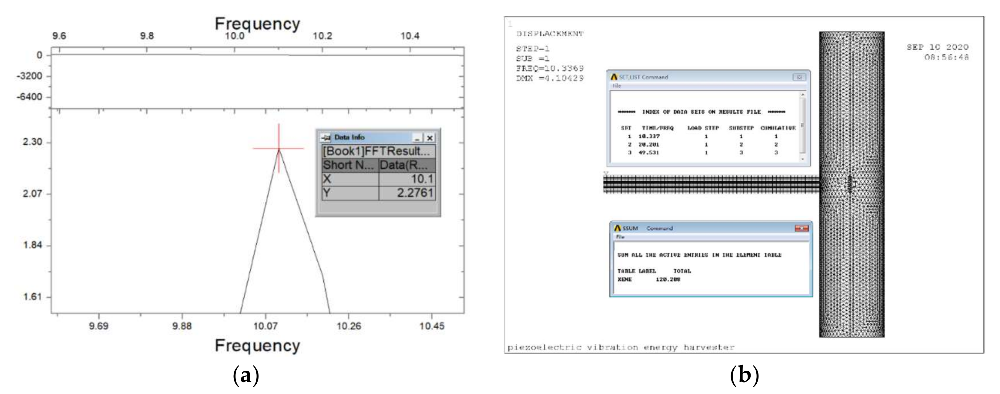
By collecting the free vibration amplitude and performing FFT (Fast Fourier Transformtion) on it, the free vibration frequency is obtained. as shown in Figure 4a.
ANSYS APDL software is used to establish experimental models, experimental model meshing, experimental model modal analysis and experimental model transient distraction. Experimental model modal analysis obtains the first-order frequency of model vibration. Then, by comparing the free vibration frequency with the first-order modal vibration frequency of modal analysis, the reliability of the model can be preliminarily verified. As shown in Figure 4. The control results of each group of experiments and , as shown in Table 4.
There are two main reasons for the error: (i) The fixed end of the cantilever beam is not completely consolidated. The length of the cantilever beam that vibrates in the experiment should be longer. This length is very small and difficult to measure. (ii) The cantilever beam is consolidated with the cylinder, so that the length of the cantilever beam is reduced. The reduced length is small and difficult to measure.
The damping ratio is obtained by the simplest and most practical free vibration attenuation method, namely
where is the attenuation rate after week, is the initial amplitude, and is the amplitude attenuated to 53.306%.
The system mass ratio can be expressed as
where the modal mass is , the kinetic energy of the system obtained by ANSYS APDL modal analysis, as shown in Figure 4b. Circular frequency , mass of cylinder , is the length, and is diameter of the cylinder, respectively.
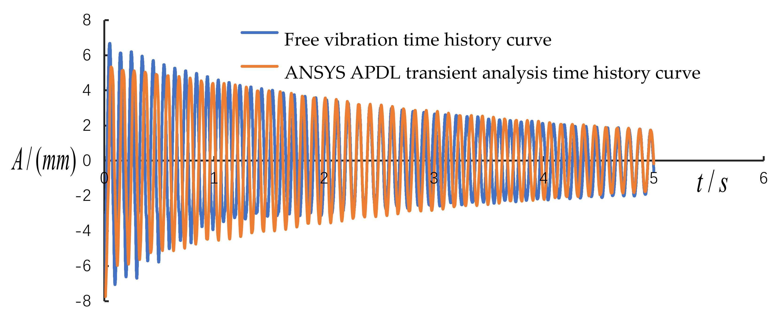
After calculating the damping ratio , through ANSYS APDL software transient analysis, the transient analysis time history curve is obtained, and it is used to compare with the time history curve of free vibration to verify the reliability of the experimental model again. As shown in Figure 5.
4.2. The Effect of on VIV Conversion Efficiency
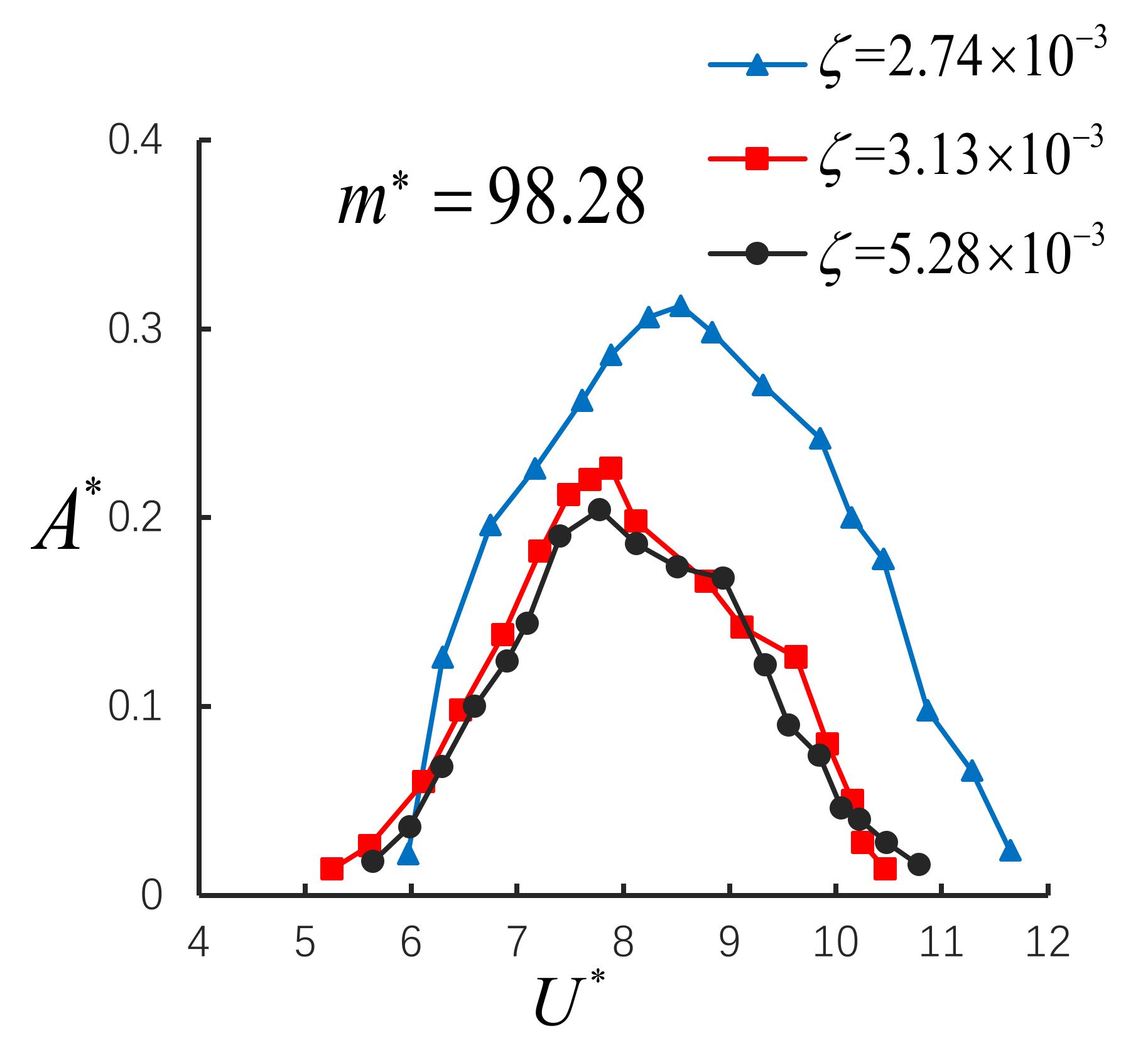
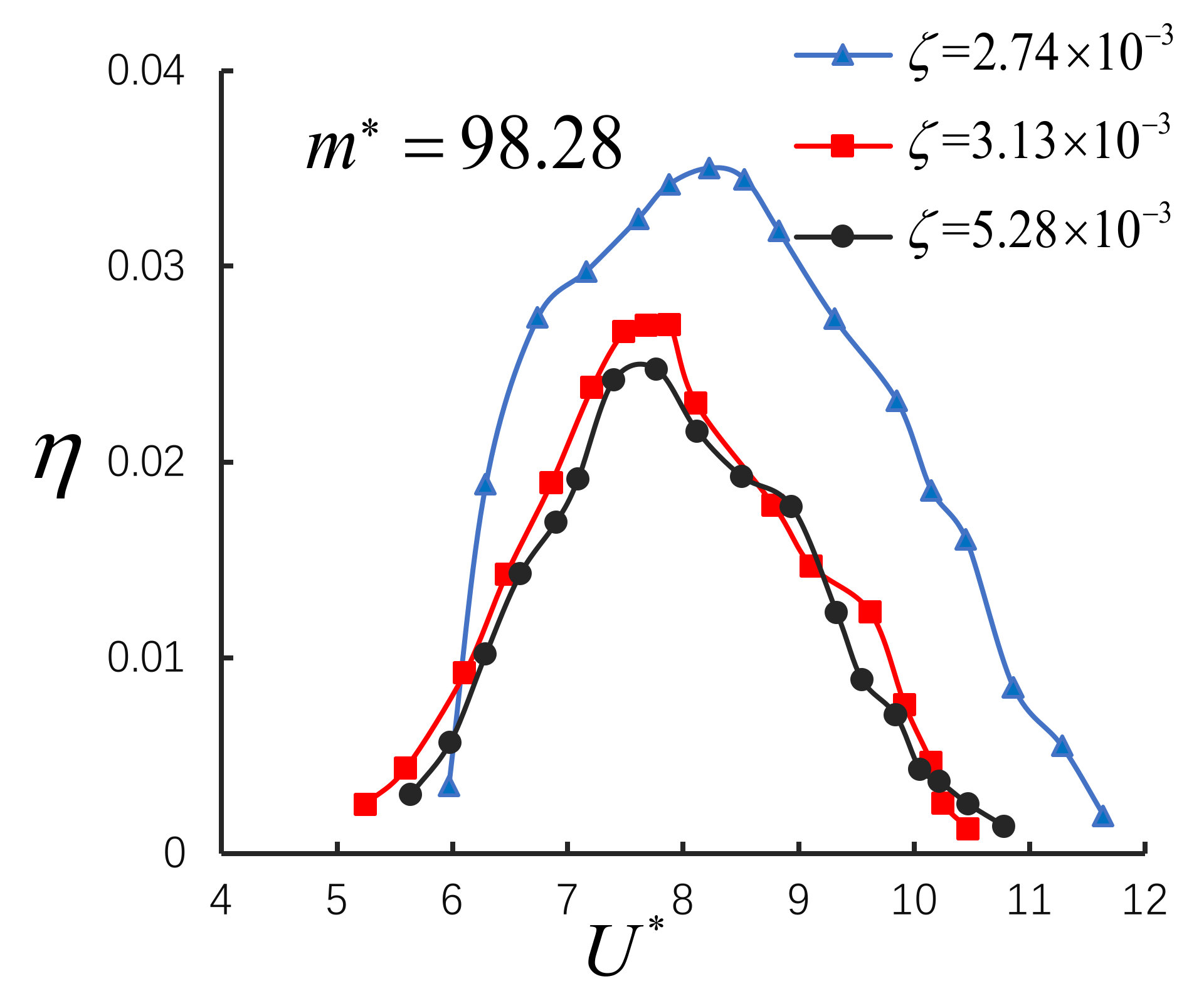
In order to explore the impact on the energy collection of the cantilever beam connected to the cylinder, VIV experiment of the same mass ratio but different damping ratio were designed, and the cylinder VIV amplitude was collected by a laser displacement meter. For the same mass ratio = 98.28, and the different damping ratio = 2.74 × 10⁻³, = 3.13 × 10⁻³, and = 5.28 × 10⁻³. The law of change of the normalized amplitude and conversion efficiency with the reduced velocity . As shown in Figure 6 and Figure 7.
We can see from Figure 6 that the smaller the damping ratio , the larger the normalized amplitude of the cantilever beam connected to the cylindrical VIV, and the longer the resonance range of the reduced velocity . In fact, this is consistent with the results of the previous mathematical model. For large mass ratio,, the damping ratio is inversely proportional to , so the smallest damping ratio = 2.74 × 10⁻³, the largest normalized amplitude value appears in the experiment, as shown in Figure 6. When = 2.74 × 10⁻³, the maximum value of conversion efficiency is the largest, the maximum conversion efficiency value is 0.035. This seems to indicate that for large mass ratio, , the trends of and are the same with , and the damping ratio has a great influence on the maximum efficiency attainable. In fact, the maximum achievable conversion efficiency might be again be governed by the product . Results are presented in Figure 7.
4.3. The Effect of on VIV Conversion Efficiency
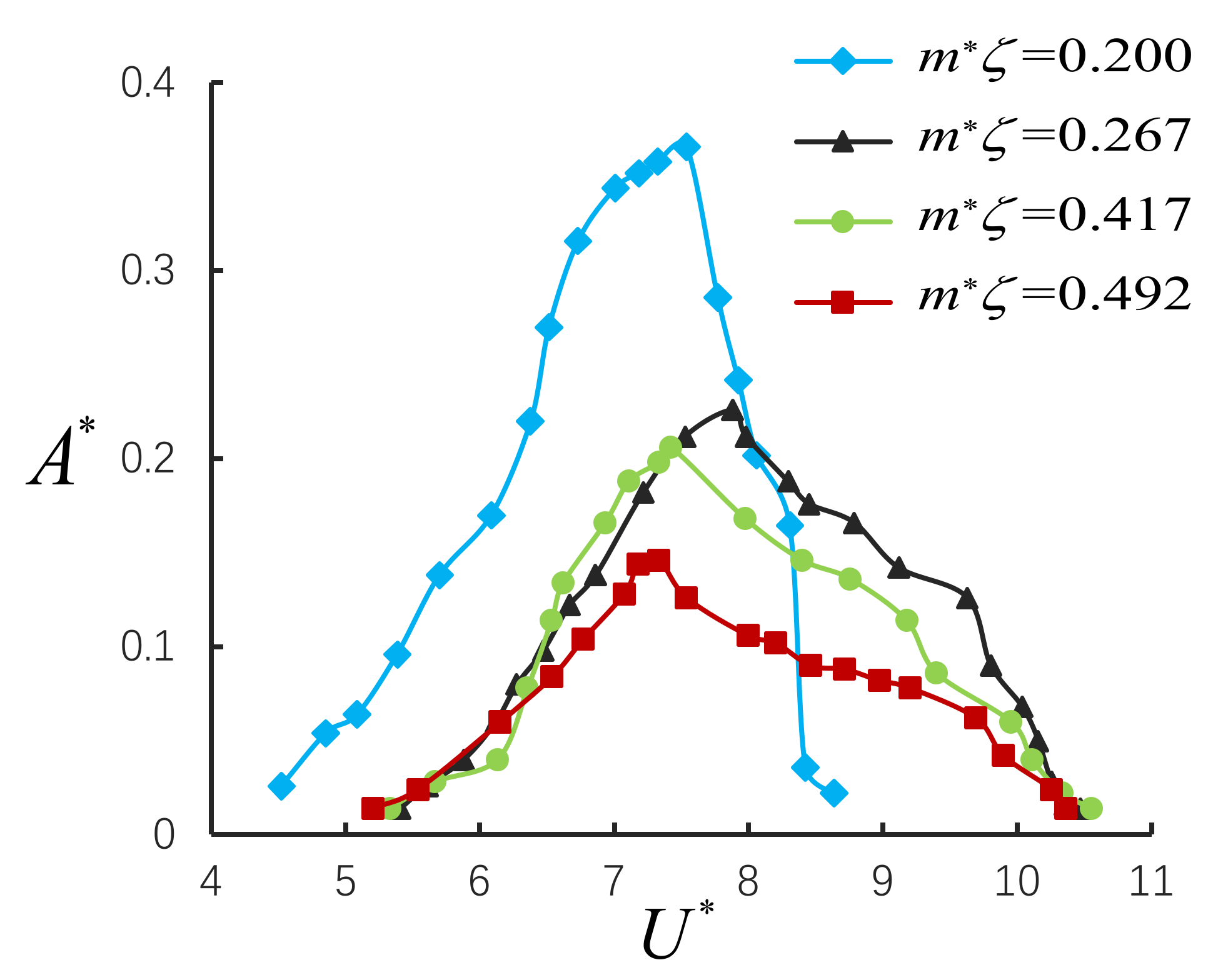
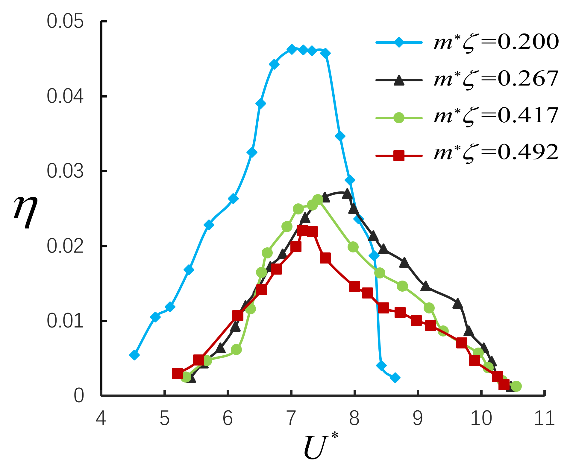
In order to explore the influence on the energy harvesting of the cantilever beam connected to the cylinder, VIV experiment of the different mass-damping parameter were designed, and to obtain the VIV amplitude of the cylinder through a laser displacement meter. For large mass ratio, , and each value of mass-damping parameter = 0.200, = 0.307, = 0.417, = 0.492, the law of change of the normalized amplitude and conversion efficiency with the reduced velocity . As shown in Figure 8 and Figure 9.
We can see from Figure 8 that the smaller the mass-damping parameter , the larger the normalized amplitude of the cantilever beam connected to the cylindrical VIV, but the resonance range of the reduced velocity is smaller. The results seem to indicate that for large mass ratio, , the peak normalized amplitude is mainly controlled by the product of , and the product of are inversely proportional, this is consistent with the expected result. So = 0.200, the normalized amplitude have maximum value, as shown in Figure 8. From the results, it seems that the value of has a relatively large impact on the energy conversion efficiency value . So, the maximum value of conversion efficiency at = 0.200 is the largest, the maximum value is 0.046. Results are presented in Figure 9.
According to the above experiment, calculate the average value of the conversion efficiency under each value , when = 0.200, the average conversion efficiency = 0.02 is the maximum. From a practical point of view, it is very interesting to efficiently extract energy from a stream in a wide range of environments. For large mass ratio, , in a specific Reynolds number range, the smaller the value of the selected cantilever beam to connect the cylinder, the larger the maximum and average efficiency of VIV energy harvesting. However, the flow rate range of the effective efficiency and the maximum energy conversion efficiency value are relatively small. Therefore, in the next study, we will reduce the mass damping ratio as much as possible.
4.4. Normalized Frequency Changes with
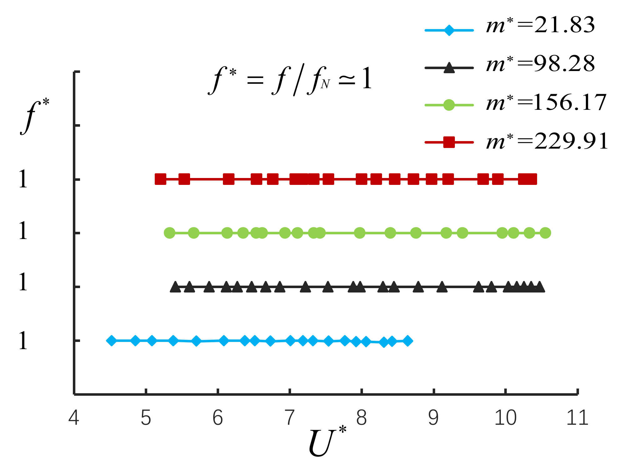
In the above experiments, the laser displacement meter recorded the time history curve data of the cantilever beam connected to the cylinder in each small experiment, and the data was transformed by FFT to obtain the resonance frequency . For , we get the change with the normalized flow velocity , as shown in Figure 10. For large mass ratio, , the normalized frequency , the locked state of VIV appears, the result is consistent with the established mathematical model.
5. Conclusions
From a practical point of view, it is very interesting to efficiently extract energy from a stream in a wide range of agricultural environments. In this paper, a cantilever beam connected to a cylindrical energy harvester is designed, a mathematical model is established for it through the VIV equation, and the expression of conversion efficiency is obtained. Two sets of experiments were designed to study the effect of , on the energy collection efficiency of the cantilever beam connected to the cylindrical VIV. There are certain differences between the results of this paper and related research, the results show: (i) For large mass ratio, , and the same mass ratio , the smaller the damping ratio , the larger the normalized amplitude . The greater the maximum energy conversion efficiency of the cantilever beam connected to the cylinder. (ii) For large mass ratio, , in the specific Reynolds number range, the smaller the mass-damping parameter , the larger the normalized amplitude . The larger the maximum and average value of VIV energy conversion efficiency . Choosing a smaller mass ratio and proper damping ratio can more effectively obtain energy from the fluid. However, the flow rate range of the effective efficiency and the maximum energy conversion efficiency value are relatively small. Therefore, in the next study, we will reduce the mass damping ratio as much as possible. (iii) For large mass ratio, , the greater the mass ratio , the greater the range of the reduced velocity where resonance occurs. Normalized frequency , a stable VIV locked state appears.
We believe that the results presented in this article are representative. From an engineering perspective, this experimental study can provide a certain theoretical reference for designing a device to extract useful energy from VIV in agricultural environments.
Author Contributions
Conceptualization, A.X. and R.L.; methodology, A.X. and R.L.; software, R.L., A.X., and Z.L.; formal analysis, A.X. and R.L.; writing—original draft preparation, Z.L.; review and editing, A.X. and R.L. and Z.L.; visualization, A.X., Z.L. All authors have read and agreed to the published version of the manuscript.
Funding
This research received no external funding.
Conflicts of Interest
The authors declare no conflict of interest.
References
- Chatterjea, S.; Havinga, P. Improving Temporal Coverage of an Energy-Efficient Data Extraction Algorithm for Environmental Monitoring Using Wireless Sensor Networks. Sensors 2009, 9, 4941–4954. [Google Scholar] [CrossRef] [PubMed]
- Farooq, M.S.; Riaz, S.; Abid, A.; Umer, T.; Zikria, Y.B. Role of IoT Technology in Agriculture: A Systematic Literature Review. Electronics 2020, 9, 319. [Google Scholar] [CrossRef] [Green Version]
- Abdelkefi, A.; Hajj, M.R.; Nayfeh, A.H. Phenomena and modeling of piezoelectric energy harvesting from freely oscillating cylinders. Nonlinear Dyn. 2012, 70, 1377–1388. [Google Scholar] [CrossRef]
- Bearman, P.W. Circular cylinder wakes and vortex-induced vibrations. J. Fluids Struct. 2011, 27, 648–658. [Google Scholar] [CrossRef]
- Zhao, M.; Cheng, L.; An, H. Numerical investigation of vortex-induced vibration of a circular cylinder in transverse direction in oscillatory flow. Ocean Eng. 2012, 41, 39–52. [Google Scholar] [CrossRef]
- Mehmood, A.; Abdelkefi, A.; Hajj, M.R.; Nayfeh, A.H.; Akhtar, I.; Nuhait, A.O. Piezoelectric energy harvesting from vortex-induced vibrations of circular cylinder. J. Sound Vib. 2013, 332, 4656–4667. [Google Scholar] [CrossRef]
- Ran, J.Y.; Wang, J.L.; Wang, R.R. A Model for Energy Harvesting from Vortex-Induced Vibration of Circular Cylinder. Adv. Mater. Res. 2014, 3248, 877–881. [Google Scholar] [CrossRef]
- Zhang, W.; Li, X.; Ye, Z.; Jiang, Y. Mechanism of frequency lock-in in vortex-induced vibrations at low Reynolds numbers. J. Fluid Mech. 2015, 783, 72–102. [Google Scholar] [CrossRef]
- Soti, A.K.; Zhao, J.; Thompson, M.C.; Sheridan, J.; Bhardwaj, R. Damping effects on vortex-induced vibration of a circular cylinder and implications for power extraction. J. Fluids Struct. 2018, 81, 289–308. [Google Scholar] [CrossRef]
- Chang, T.J.; Lua, K.B. Simulation on Vortex Induced Vibration of Circular Cylinder. J. Phys. Conf. Ser. 2020, 1509, 12–24. [Google Scholar] [CrossRef]
- Rodríguez-Robles, J.; Martin, Á.; Martin, S.; Ruipérez-Valiente, J.A.; Castro, M. Autonomous Sensor Network for Rural Agriculture Environments, Low Cost, and Energy Self-Charge. Sustainability 2020, 12, 5913. [Google Scholar] [CrossRef]
- Haseeb, K.; Ud Din, I.; Almogren, A.; Islam, N. An Energy Efficient and Secure IoT-Based WSN Framework: An Application to Smart Agriculture. Sensors 2020, 20, 2081. [Google Scholar] [CrossRef] [PubMed]
- Zhimin, C.; Xun, R.; Guangzhong, C. Design of a self-powered power based on piezoelectric energy harvesting technology. Electron. Des. Eng. 2016, 10, 1674–6236. [Google Scholar]
- Xinghao, L.; Kaiyi, Z.; Lihua, Y.; Xiantao, Q. Design of Intelligent Water Quality Wireless Online Monitoring System Based on Zigbee. Think Tank Times 2019, 189, 234–235. [Google Scholar]
- Bearman, P.W. Vortex shedding from oscillating bluff bodies. Ann. Rev. Fluid Mech. 1984, 16, 195–222. [Google Scholar] [CrossRef]
- Sarpkaya, T. A critical review of the intrinsic nature of vortex-induced vibrations. Fluids Struct. 2004, 19, 389–447. [Google Scholar] [CrossRef]
- Williamson, C.H.K.; Govardhan, R. Vortex-induced vibrations. Ann. Rev. Fluid Mech. 2004, 36, 413–455. [Google Scholar] [CrossRef] [Green Version]
- Khalak, A.; Williamson, C.H.K. Fluid forces and dynamics of hydroelastic structure with very low mass and damping. J. Fluids Struct. 1997, 11, 973–982. [Google Scholar] [CrossRef]
- Khalak, A.; Williamson, C.H.K. Motons, forces and mode transitions in vortex induced vibrations at low mass-damping. J. Fluids Struct. 1999, 13, 813–851. [Google Scholar] [CrossRef]
- Allen, J.J.; Smits, A.J. Energy Harvesting eel. J. Fluids Struct. 2001, 15, 629–640. [Google Scholar] [CrossRef] [Green Version]
- Bernitsas, M.; Raghawan, K.; Ben-Simon, Y.; Garcia, E.M.H. VIVACE (vortex induced vibration for aquatic clean energy): A new concept in generation of clean and renewable energy from fluid flow. J. offshore Mech. Arct. Eng. 2008, 130, 41–59. [Google Scholar] [CrossRef]
- Barrero-Gil, A.; Alonso, G.; Sanz-Andres, A. Energy harvesting from transverse galloping. Sound Vib. 2010, 329, 2873–2883. [Google Scholar] [CrossRef] [Green Version]
- Zhu, G.; Haase, M.; Wu, C.H. Modelling the capacity of a novel flow-energy harvester. Appl. Math. Model. 2009, 33, 2207–2217. [Google Scholar] [CrossRef]
- Barrero-Gil, A.; Pindado, S.; Avila, S. Extracting energy from Vortex-Induced Vibrations: A parametric study. Appl. Math. Model. 2012, 36, 3153–3160. [Google Scholar] [CrossRef] [Green Version]
- Perelli, A.; Faggioni, O.; Soldani, M.; Zunino, R. Design and performance analysis of a piezoelectric generator by Von Karman vortexes for underwater energy harvesting. J. Energy Chall. Mech. 2014, 1, 127–132. [Google Scholar]
- Gao, X.; Shih, W.H.; Wan, Y.S. Flow Energy Harvesting Using Piezoelectric Cantilevers With Cylindrical Extension. IEEE Trans. Ind. Electron. 2013, 60, 1116–1118. [Google Scholar] [CrossRef]
- Jieli, F.; Wei-Ping, H. Numerical simulation of 2-DOF vortex-induced video of a long riser. J. Vib. Shock. 2012, 31, 65–68. [Google Scholar]
- Zhumei, L.; Lixiang, Z. Study on the parameters affecting the energy obtained from vortex-induced vibration. J. Vib. Shock. 2014, 33, 12–15. [Google Scholar]
Figure 1.
Overall structure.

Figure 2.
The annular wind tunnel.

Figure 3.
Diagram of experimental model and sensor.

Figure 4.
(a) FFT (Fast Fourier Transform) to get the natural frequency; (b) ANSYS APDL modal analysis.
Figure 4.
(a) FFT (Fast Fourier Transform) to get the natural frequency; (b) ANSYS APDL modal analysis.

Figure 5.
Comparison chart of free vibration and ANSYS APDL transient analysis time history curve.

Figure 6.
with the change of of experiment Ⅱ.

Figure 7.
with the change of of experiment Ⅱ.

Figure 8.
with the change of of experiment Ⅱ.

Figure 9.
with the change of of experiment Ⅱ.

Figure 10.
with the change of of experiment Ⅱ.


Table 1.
Parameters of cylindrical model.
| Cylinder | D (mm) | L (mm) | L/D | m (g) |
|---|---|---|---|---|
| 1 | 50 | 252 | 5.04 | 10.8 |
| 2 | 50 | 252 | 5.04 | 59.5 |
| 3 | 50 | 252 | 5.04 | 94.6 |
| 4 | 50 | 252 | 5.04 | 139.3 |
Table 2.
Parameters of experiment I model.
| Number | Cylinder | ||||
|---|---|---|---|---|---|
| 1 | 2 | 98.28 | 0.00274 | 6.7 | 5.9~11.6 |
| 2 | 2 | 98.28 | 0.00313 | 10.1 | 5.2~10.4 |
| 3 | 2 | 98.28 | 0.00528 | 11.7 | 5.6~10.7 |
Table 3.
Parameters of experiment II model.
| Number | Cylinder | ||||
|---|---|---|---|---|---|
| 1 | 1 | 21.83 | 0.00915 | 0.200 | 4.5~8.6 |
| 2 | 2 | 98.28 | 0.00313 | 0.307 | 5.2~10.4 |
| 3 | 3 | 156.17 | 0.00267 | 0.417 | 5.3~10.5 |
| 4 | 4 | 229.91 | 0.00214 | 0.492 | 5.2~10.3 |
Table 4.
Parameters of comparison result of and .
| Number | Error | ||
|---|---|---|---|
| I 1 | 6.7 | 7.0 | 4.28% |
| I 2 | 10.1 | 10.3 | 1.94% |
| I 3 | 11.7 | 12.4 | 5.64% |
| II 1 | 26.1 | 26.6 | 1.88% |
| II 2 | 10.1 | 10.3 | 1.94% |
| II 3 | 9 | 9.3 | 3.22% |
| II 4 | 7.8 | 8.1 | 3.70% |
© 2020 by the authors. Licensee MDPI, Basel, Switzerland. This article is an open access article distributed under the terms and conditions of the Creative Commons Attribution (CC BY) license (http://creativecommons.org/licenses/by/4.0/).
Share and Cite
MDPI and ACS Style
Liao, Z.; Xiong, A.; Liu, R. Study on Parameterization of Vortex-Induced Vibration Energy Harvester in Agricultural Environment. AgriEngineering 2020, 2, 511-522. https://0-doi-org.brum.beds.ac.uk/10.3390/agriengineering2040034
AMA Style
Liao Z, Xiong A, Liu R. Study on Parameterization of Vortex-Induced Vibration Energy Harvester in Agricultural Environment. AgriEngineering. 2020; 2(4):511-522. https://0-doi-org.brum.beds.ac.uk/10.3390/agriengineering2040034
Chicago/Turabian StyleLiao, Zhangyi, Anping Xiong, and Renxin Liu. 2020. "Study on Parameterization of Vortex-Induced Vibration Energy Harvester in Agricultural Environment" AgriEngineering 2, no. 4: 511-522. https://0-doi-org.brum.beds.ac.uk/10.3390/agriengineering2040034