1. Introduction
Since the invention of the thermostat by Warren Johnson in 1883, mankind dreams of intelligent and automated environments. When applied to buildings, the possible applications of this concept are countless: from the improvement of the safety and the comfort of occupants, to the application of energy efficiency measures, and the care for the disabled and the elderly, just to mention a few [
1]. Among these, energy efficiency has become one of the most important aspects in the design and management of both residential and commercial buildings [
2], also following the increasing concerns on global warming and on fossil fuels depletion. In particular, when it comes to non-residential sites, such as, public agencies, commercial, and industrial buildings, the concept of energy efficiency has an even greater bearing, by dealing with larger amounts of heterogeneous users, equipment, and facilities. This in fact implies larger opportunities of energy savings, which in the case of public buildings, may be particularly critical, due to the use of public money.
The efficient use of energy intensive equipment, such as Heating, Ventilation, and Air Conditioning (HVAC) systems, plays a key role for the development of sustainable energy buildings. It is worth noting that this applies not only to the design stage, i.e., by making use of high performing insulating materials, advanced construction technologies, efficient equipment, or renewable sources [
2,
3], but also to the operation stage, i.e., by defining how equipment and energy resources must be operated to ensure an efficient use of energy [
4]. The efficient operation of equipment and energy resources, particularly in the case of large buildings, requires the monitoring and control of several parameters, concerning the use of facilities (i.e., the presence of users, the thermo-hygrometric conditions in rooms, etc.), such as well as the working condition of devices and equipment [
5]. In this context, the recent diffusion of Information and Communication Technology (ICT) solutions and, in particular, of the Internet of Things (IoT) paradigm, allowed the development of the smart building concept [
6], which is opening the way for improved energy management capabilities, thanks to the use of advanced monitoring and control functions over heterogeneous sensors and devices [
7,
8].
Of particular interest is the application of such functionalities in complex systems, such as campuses, where the coordinated monitoring and control of clusters of buildings and dispersed resources is required to implement the optimal management of the whole system. In this kind of applications, distributed and holonic control architectures are suggested by the scientific literature, by following the recent research trends in the monitoring and control of Distributed Energy Resources (DERs) in Smart Grids [
9]. In particular, decentralized control architectures inherited by smart and micro-grids management systems [
10,
11] have been proposed as viable solution also in smart campus environments, such as suggested in [
12,
13].
The application of advanced monitoring and control strategies (and of the related ICT solutions) relies on the availability of proper communication infrastructures. The complexity and the installation costs of proper communication systems represent one of most critical aspects of such application. The installation of wired systems, such as optical fiber in large areas (e.g., where distances are on the order of hundreds of meters) or ethernet networks in small areas (e.g., where distances are below 100 m) may present relevant costs, particularly in old buildings or in complex scenarios, such as that of smart campus, where the distance between buildings may be up to dozen or even hundreds of meters. For this reason, the use of wireless networks are gaining momentum, particularly when large area or hybrid environments are taken into account. Usually, Local Area Network (LAN) technologies like IEEE802.11 (WiFi) are used inside buildings, leveraging previously deployed infrastructures. On the other hand, the use of performing wireless technologies, such as WiFi, presents coverage capacity limitations, both in indoor environments (i.e., between different stories of the same building) and in outdoor scenarios (i.e., between different buildings). Last, the use of Power Line Communication (PLC), which makes use of existing electrical infrastructures inside buildings, can be successfully implemented only on the same portion of the electrical network, by thus limiting its application only to very simple user systems. When it comes to more complex systems, such as a campus, a mixed scenario with multiple buildings and external areas is more realistic, leading to consider a Wide Area Network (WAN) approach. In particular, the use of Low Power Wide Area Network (LPWAN) solutions is emerging as a viable option, thanks to their large coverage, low complexity and low power consumption. The use of the LoRaWAN technology could thus represent a very promising solution, due to its good coverage capabilities (both in outdoor and in hybrid environments), whereas its most critical aspect is represented by the relative low data throughput and duty cycle limitation. In addition, the adoption of heterogeneous IoT protocols and devices may present relevant issues, making their large-scale integration cumbersome.
Even if the LoRaWAN technology may well fit this kind of application, its main drawback is represented by the limited data throughput, which makes its application questionable. Starting from this remark, in this study we try to answer the following questions:
is the LoRaWAN technology able to handle the amount of data and the refresh time intervals required for the monitoring and control of distributed energy resources in a smart campus?
how many devices can be monitored and controlled by a single LoRaWAN gateway?
can the LoRaWAN infrastructure be integrated as complementary solution in an existing monitoring and control architecture?
To answer the first question, we analyzed the scientific literature to identify the monitoring and control architectures proposed for the management of distributed energy resources in complex systems. A generalized architecture was thus determined, and then used as reference architecture to determine the refresh time intervals and the type of messages exchanged between the different intelligent devices and the related supervisory entities. Secondly, a proper data model structure was defined to allow the computation of the payload of the communication. It is worth to note that, to the best of the authors’ knowledge, the detailed definition of a smart campus use–case, and of the related data model, were never presented in the literature, thus making this contribution part of the novelty of this study. Finally, a proper architecture based on the LoRaWAN class A technology was proposed, and its feasibility was evaluated by verifying its ability of transmitting the required amount of data in the given refresh time intervals. The evaluation is carried out by computing the Time-on-Air duration of monitoring and supervisory control messages. Starting from the results obtained above, we answered the second question by computing the number of devices that can be handled by a single LoRaWAN gateway. The computation has been carried out by considering two different scenarios: a worst case scenario, where each installed device operates with the maximum expected payload, and a realistic scenario, composed by a mixed set of simple sensors and complex devices operating with the expected average uplink and downlink payload. Last, to answer the third question, we proposed an IoT architecture able to transparently manage different communication protocols. The proposed architecture operates only at the application layer, thus not involving the implementation of specific communication techniques. The latter are indeed provided by the LoRaWAN infrastructure, without requiring any modification or custom implementation. Finally, for sake of completeness, the experimental validation of the technical suitability of a LoRaWAN implementation is provided in the appendix, by presenting the results of the coverage and latency measurements carried out in the main campus of the Federal University of Rio Grande do Norte, Brazil.
The structure of the paper is organized as follows. In
Section 2, the application of distributed control architectures in smart campus environments is briefly discussed, by focusing on the distributed management of energy resources and on the role of IoT and LPWANs.
Section 3 describes the proposed IoT architecture integrating LoRaWAN. In
Section 4 the scalability analysis of the proposed architecture is presented, by first introducing the smart campus use case, and the related data model. Finally, in
Section 5 the results of the study are summarized and the final remarks are discussed. In the
Appendix A the LoRaWAN technology and some of its available implementations are discussed together with the real scenario experimental validation in terms of latency and coverage.
2. Distributed Control and IoT Architectures in Smart Environments
The scenario where objects, sensors and actuators are communicating to each other to form an automated place is called smart place. Depending on the context, the application of automation and of the related ICT solutions can lead to different scenarios, such as a smart home, a smart building, a smart factory, a smart campus, or even a smart city. Each of these environments is characterized by specific features and requires different control approaches. While in a smart home, for instance, the physical structure is composed by a limited number of spaces (e.g., some rooms), appliances and equipment, a smart campus is formed by many different areas. University campuses are in fact formed by sectors, blocks, classrooms, laboratories, offices, etc., each with different functions, equipment, and independent staff, thus requiring specific management capabilities. In this section, the recent research trends on the monitoring and control of distributed energy resources in complex systems are briefly discussed, by introducing decentralized control architectures, and discussing the role of IoT and of LPWANs in smart environments.
2.1. Distributed Management of Energy Resources
Several research streams recently dealt with the efficient operation of equipment and energy resources in smart buildings, by investigating different fields. Examples are the optimization of HVAC systems based on Model Predictive Control (MPC) algorithms or Neural Networks (NNs) [
14,
15,
16,
17], or the application of flexible control strategies, Demand Side Management (DSM) actions, and Demand Response (DR) programs [
2,
18,
19,
20]. The application of such control strategies is implemented in single family houses through the so-called Home Energy Management Systems (HEMSs), such as well as in large buildings, by means of Building Energy Management Systems (BEMSs). In the latter case, advanced control functions are usually defined by supervisory levels and then communicated to local controllers and actuators by means of local networks. Conversely, the implementation of DSM actions and DR programs, which involves the participation of third-party agents, such as Distribution System Operators (DSOs) or independent aggregators, requires the use of WANs [
7,
17].
The typical monitoring and control architectures usually implemented in smart HEMSs and BEMSs consist of two main layers: the control layer, and the supervisory layer. The control layer usually implements low-level monitoring and control functions over heterogeneous sensors and devices (equipment, appliances, gateways, and controllers). At this stage, different communication technologies are typically used: from field buses (such as BACnet or Modbus) to wireless protocols (such as WiFi, Z-Wave, ZigBee, or Bluetooth). At the upper-level, the supervisory layer is responsible for the supervisory monitoring and control of the whole system: it usually computes job schedules of distributed energy resources (from generators to loads and actuators), and then communicates this information to local gateways and controllers, which are responsible for the low-level implementation of the related control strategies. The supervisory layer is also responsible for the application of DSM actions and DR programs, by typically making use of WAN solutions. In this case, active power limitations are usually required for a given time period and communicated by third-party entities (such as DSOs or independent operators) well in advance [
21].
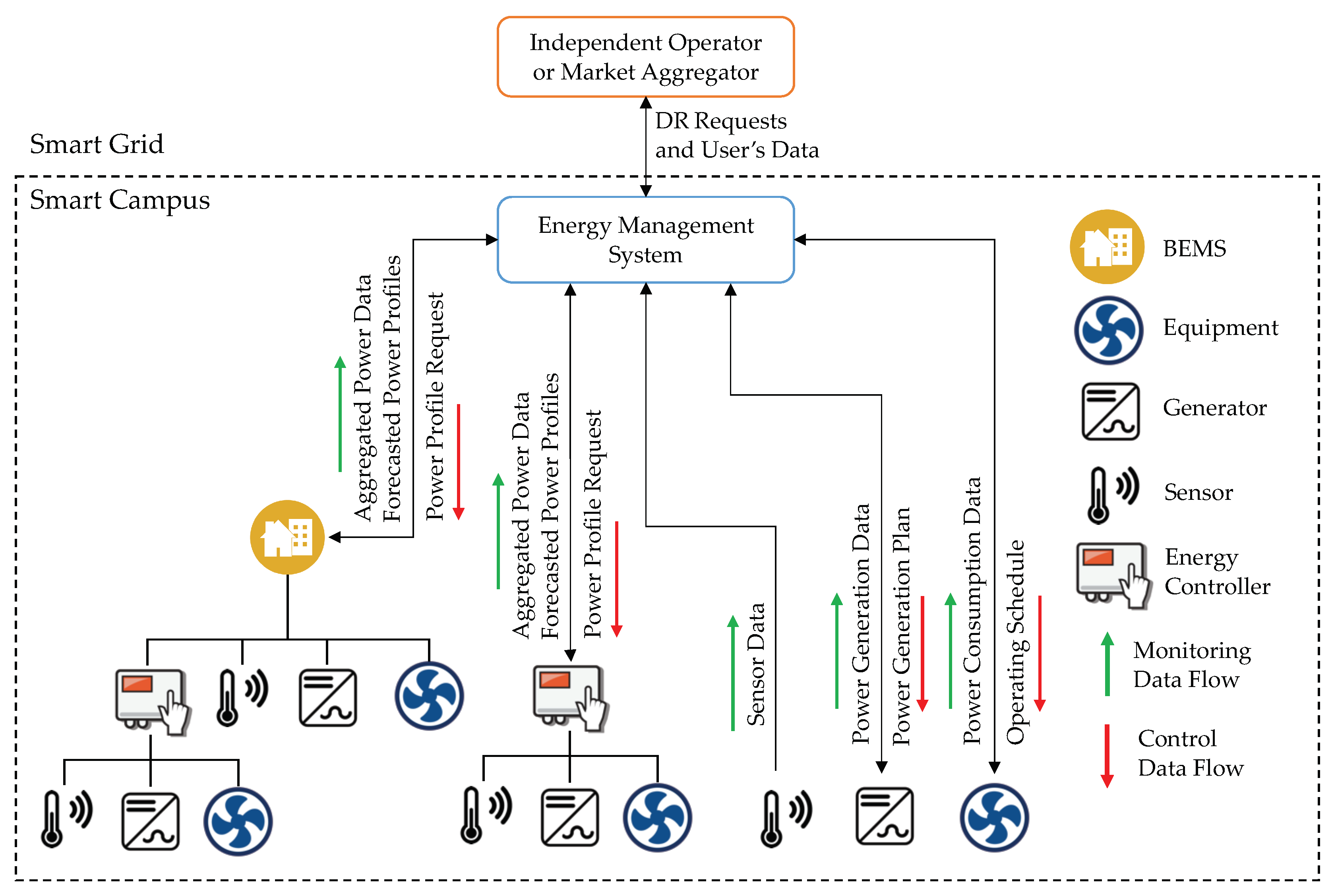
When applied to smart campus environments, the application of coordinated monitoring and control functions over distributed resources (including isolated generators and equipment, such as well as entire buildings) requires the implementation of more complex architectures. In this case, decentralized control architectures can be adopted. Supervisory Energy Management Systems (EMSs) are in charge for the strategic coordination and scheduling of supervised devices and resources (from single equipment to entire buildings), by following system optimization objectives and by considering DR requests provided by external entities (i.e., smart grid operators). The schematic representation of such architecture is shown by the diagram of
Figure 1. It is worth noting that an example of a real implementation of an EMS framework following this approach was proposed in [
22].
Concerning the monitoring and control functions applied by the supervisory EMS, three main scenarios can be identified, according to aggregation level that can be implemented over the supervised resources. In its most simple formulation, sensors, generators, and electrical equipment can be directly supervised by the EMS. In this case, the supervisory control functions are implemented by computing the power generation and consumption profiles of generators and loads, respectively. Each power profile is defined as the active power produced or consumed by the specific physical entity over a given time horizon (typically 24 h) with a system-defined time step (usually 15 min). Power profiles are determined for all of the supervised entities by taking into account the users’ requests, weather forecasts, strategic schedules and constraints (set by the system administrator), historical data (used by machine learning algorithms), and current measurements from distributed sensors (i.e., current weather data, state of charge of storage units, etc.). For each physical entity, one or more profiles can be generated depending on the possible different configurations of the resource. HVAC systems, for instance, may have different feasible demand profiles, depending on the considered comfort levels and on time-shifting or peak-clipping options (implemented by means of thermal storage systems). In this scenario, power profiles are usually determined by the supervisory EMS, which is also responsible for determining the most suitable solution for each physical entity, and by then providing the related job schedules to the supervised resources. Typical job schedules are represented by temperature set-point profiles to HVAC systems, power limitation profiles to renewable generators, or chargedischarge schedules to electrical storage systems.
At a higher aggregation level, sensors, generators, and electrical equipment are not directly supervised by the EMS, but by local energy controllers (i.e., according to the power matcher concept [
9]). In this case, power profiles are determined for each resource by local intelligent devices, and then aggregated as a class of net power profiles. Data from supervised sensors are used by local intelligence to evaluate the energy generation and demand of physical entities, but not forwarded to the upper supervisory layer (i.e., the EMS). The set of computed net power profiles are provided to the supervisory EMS, which is in charge for the selection of the most suitable net power schedule. Once selected, the net power profile selected by the EMS is forwarded to the local energy controller, which is in charge for ensuring that the given profile is accomplished, by properly controlling all the supervised entities.
At the highest aggregation level, which typically corresponds to the smart building scenario, complex sets of sensors, equipment, and energy resources (which may be independent or aggregated by local energy controllers) are supervised by a BEMS. In this case each BEMS (i.e., each smart building) is responsible for computing the forecast or feasible power profiles for each supervised entity, and for collecting the class of net power profiles computed by supervised energy controllers. The set of all of the computed power profiles are then aggregated as a new set of net power profiles, and forwarded to the supervisory EMS, by following the same monitoring and control process described for the local energy controller scenario.
The main advantages of distributed control architectures can be summarized as follows:
high scalability and flexibility: the use of decentralized intelligence doesn’t require the complete implementation of the monitoring and control functions of all of the supervised nodes in the supervisory layer. This allows the extension and modification of the supervised physical system (e.g., by adding new resources or modifying the existing configuration) without sensibly affecting the structure of the supervisory EMS;
reduced information throughput between the supervisory level and the system nodes: the implementation of distributed control functions at local nodes or aggregators allows the reduction of the computational complexity of the supervisory EMS. This also allows to reduce the rate of information exchange among the local nodes and the supervisory level, for both the monitoring and the control;
relaxed latency requirements for supervisory communication: the supervisory layer does not implement high-speed controls over the single nodes of the system, but provides predefined job schedules or power profile requests well in advance with respect to the time of actuation (up to three hours), and implements monitoring functions with refresh time interval of usually 15 min. Consequently, large communication latencies (on the order few minutes) for supervisory functions can be allowed.
Finally, it must be noted that the adoption of distributed control architectures does not usually require a performing communication infrastructure among the supervisory level and the single nodes of the control architecture, due to the small amount of information and to the large time intervals involved in the process (from 15 min for monitoring, to hours for scheduling).
2.2. The Role of IoT in Smart Environments
The literature review on the IoT area, such as well as its technological origin, is multidisciplinary. Many advances were necessary to make IoT, such as we know now, possible: from the hardware, to build ever smaller and smarter devices, passing through the communication technologies which allow wider covering distances and less energy consumption, the cloud computing, the storage of big amount of data, and the software industry.
IoT covers an extremely comprehensive area and can be applied in many sectors. From a pillar in Industry 4.0 to the way we take care of elderly people, IoT has been infiltrating in everyday life becoming an ubiquitous and pervading technology.
The use of IoT devices and applications in smart environments is nowadays a widespread practice. In smart homes, for instance, ubiquitous technologies are used to deal with the comfort, the healthcare, the safety, the security, and the energy conservation in dwellings [
23]. Concerning energy savings, it must be noted that the monitoring of water and electricity consumption represents one of the main Key Performance Indicator (KPI) of energy efficiency in buildings [
24], thus making this measurement step, essential. When it comes to smart buildings, additional functions are usually implemented, by including the monitoring of shared areas and facility equipment, such as elevators, toilets, patios, parking, etc. In the case of smart environments there are also concerns about the management of security, transportation, and other public services, thus calling for proper IoT architecture to support these kind of functionality. In particular, considering wider areas such as smart campuses, the employed IoT system must provide some LPWAN connectivity, which can deal with these demands [
25,
26,
27,
28,
29,
30]. Finally, in the context of smart cities, the goals can be more ambitious and reach more people, by aiming at sustainability, improving the life conditions of the population, and encouraging the creation of a creative economy [
31,
32,
33].
As IoT is used for more and more purposes, several isolated implementations appear and, along with the lack of interoperability, the need for standardization also arises. A relevant effort was made by the academic community to propose reference architectures for IoT applications, and many solutions were proposed. A survey of these proposals can be found in [
34]. Some of them clearly show, in terms of functional views, the features and services that should compose an IoT environment. Services such as device management, security, and communication can be seen as independent in terms of technology [
35], thus giving designers many possibilities in terms of implementation of individual services.
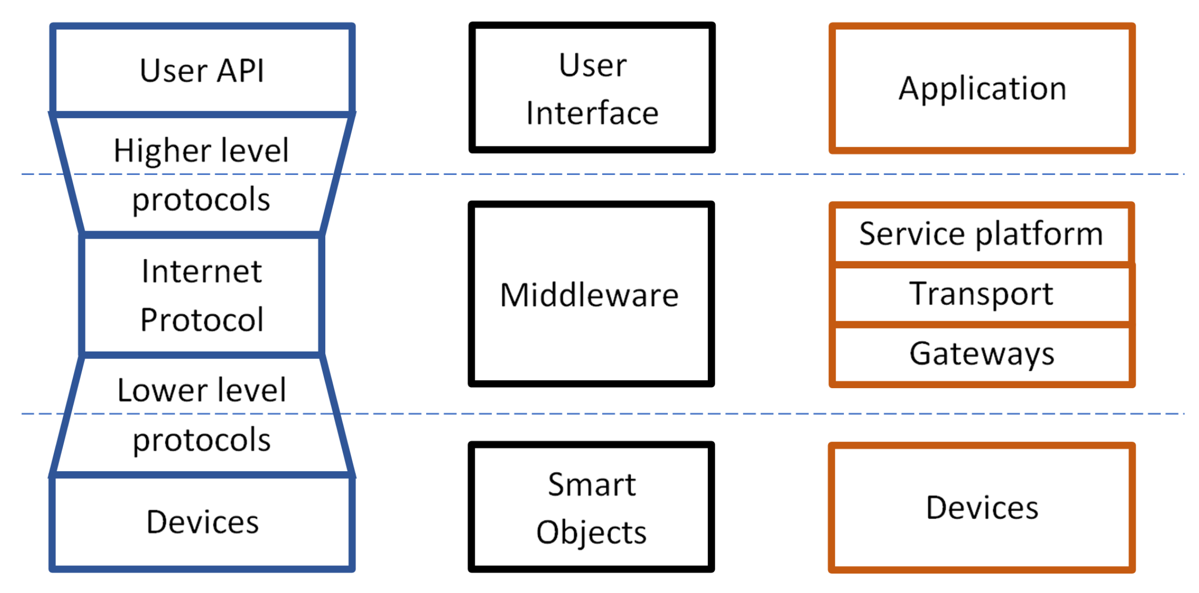
Figure 2 shows the possible views of an IoT architecture. The simplest view is where every IoT application is composed by smart objects equipped with processing power and Internet connection, a middleware, and a user interface (see
Figure 2 central view). All these components are part of the IoT architecture, although the middleware concentrates most of the functionalities.
A smart applications can be built in many ways. A recommended reference architecture is described in [
36]. The leftmost view of
Figure 2 represents the typical implementation of an IoT system, where smart devices are interconnected through wired and wireless networks. In this kind of network, devices are typically responsible for sensing and pre-processing the raw data before communicating with a gateway, which provides connection with a higher level network. The rightmost view of
Figure 2 represents the IoT Service Platform and Enabler, which contains all the software applications which implement the main functionalities of the IoT platform, including the Application Programming Interfaces (APIs - visibles in the first view of
Figure 2), such as well as additional features, such as security, availability, etc. The Application layer includes all the software applications which are specifically designed for the considered task, such as building automation or smart energy management.
Evaluating the current solutions proposed by the literature, it is clear that the IoT middleware plays an indispensable role. It is responsible for the most part of the IoT architecture functionalities, which include: device management, security, application logic, storage, rules logic, and, along with graphical user interface, the intermediation between users and devices. Besides, a cloud infrastructure serves as the IoT middleware environment, acting as a Platform as a Service (PaaS) paradigm and providing advantages as: horizontal scalability for processing power and storage, data backup, redundancy, and high availability.
An example of an IoT architecture than could be applied in complex smart environments, such as smart campuses, is the SaIoT (Smart Automation using Internet of Things) architecture [
37,
38,
39], which was first developed for smart home and building applications. This architecture has been successfully in many measurement applications, such as water and electric energy consumption [
40,
41], by also including the computation of proper KPIs.
2.3. Low Power Wide Area Networks
The communication for IoT applied to smart environments can be carried out in several ways. Backend servers use traditional Internet infrastructures. Connectivity of IoT smart objects is mainly wireless: the most popular choices are technologies like Bluetooth, ZigBee, Z-Wave, and Wi-Fi, if the distances are up to 100 m. Beyond that range, there is the new field of the LPWAN technologies, where LoRaWAN and SigFox are the most widespread ones. Everything started considering that, in order to be effective, large coverage, network scalability, low-cost and low-power consumption are all fundamental requirements. Hence, LPWAN approach has been suggested as a viable answer to these requests. In particular, the LPWAN technologies trade off radio coverage, node density and power consumption with relatively long update rate. Generally speaking, LPWAN is an umbrella for covering those technologies that typically:
Operate in the sub-GHz unlicensed bands (avoiding the over-crowded and shorter range 2.4 GHz band); regional limitations may arise, which are usually accomplished by using “listen-before-talk” and duty-cycle based strategies;
Leverage on narrowband modulation, resulting in a limited raw throughput on one side, but providing very good receiver sensitivity (allowing a link budget on the order of 150 dB) on the other one;
Implement simple and low demanding protocol stacks complemented by simple communication infrastructure (thus minimizing both the power consumption and the cost); thus, end nodes are kept simple and the complexity is moved into the backend servers.
In particular, referring to the latter aspect, the network topology is a star (i.e., single-hop network), mimicking the approach typically pursued by mobile communications (in which mobile devices connect to a base station controlled by a base station manager). It has to highlight that mobile communications, despite partially overlap with LPWAN target scenarios, are an ideal complement and, especially when 5G systems will be available, could be used for implementing the backbone of a wireless multi-tier approach. In some papers, such possible integration has been discussed [
42,
43].
Considering the heterogeneous requirements of the Smart Campus application the most suitable LPWAN solution is LoRaWAN, whose main features are flexibility, scalability, wide diffusion, and module availability from many manufacturers. Moreover, the technical properties of LoRa (e.g., the virtual channels for implementing adaptive datarate) and the possibility to build proprietary infrastructure make LoRaWAN unique. On the other hand, SigFox is not suitable for smart campus since it operates on a third-party service provider, and it suffers from low datarate and fixed number of message per day. For sake of completeness, in
Appendix A is reported an overview of LoRaWAN technology with a discussion of its features. An experimental validation of its suitability for the scope of this paper (in terms of coverage and latency) is also included.
3. The Proposed IoT Architecture for a Smart Campus
In this work, we propose an IoT architecture capable of covering a whole campus, in order to monitor and control energy resources. A smart campus environment brings new issues which require innovative solutions. In fact, the most critical seems to be the coverage area which will be extended through LPWAN technology. In particular, such as stated in
Section 2.3, LoRaWAN is used in this work. Aside from the covering range extension, other features are also desired. They are:
Representation in the system of the physical locations of a campus as departments, blocks, classrooms, etc.;
Access control to device management and data per location;
Different levels of users: system administrator, local administrator, intern user per location, public user, etc.;
These last features have been implemented in the proposed solution, but they are not the focus of this paper. Instead, the description is concentrated on the covering range extension.
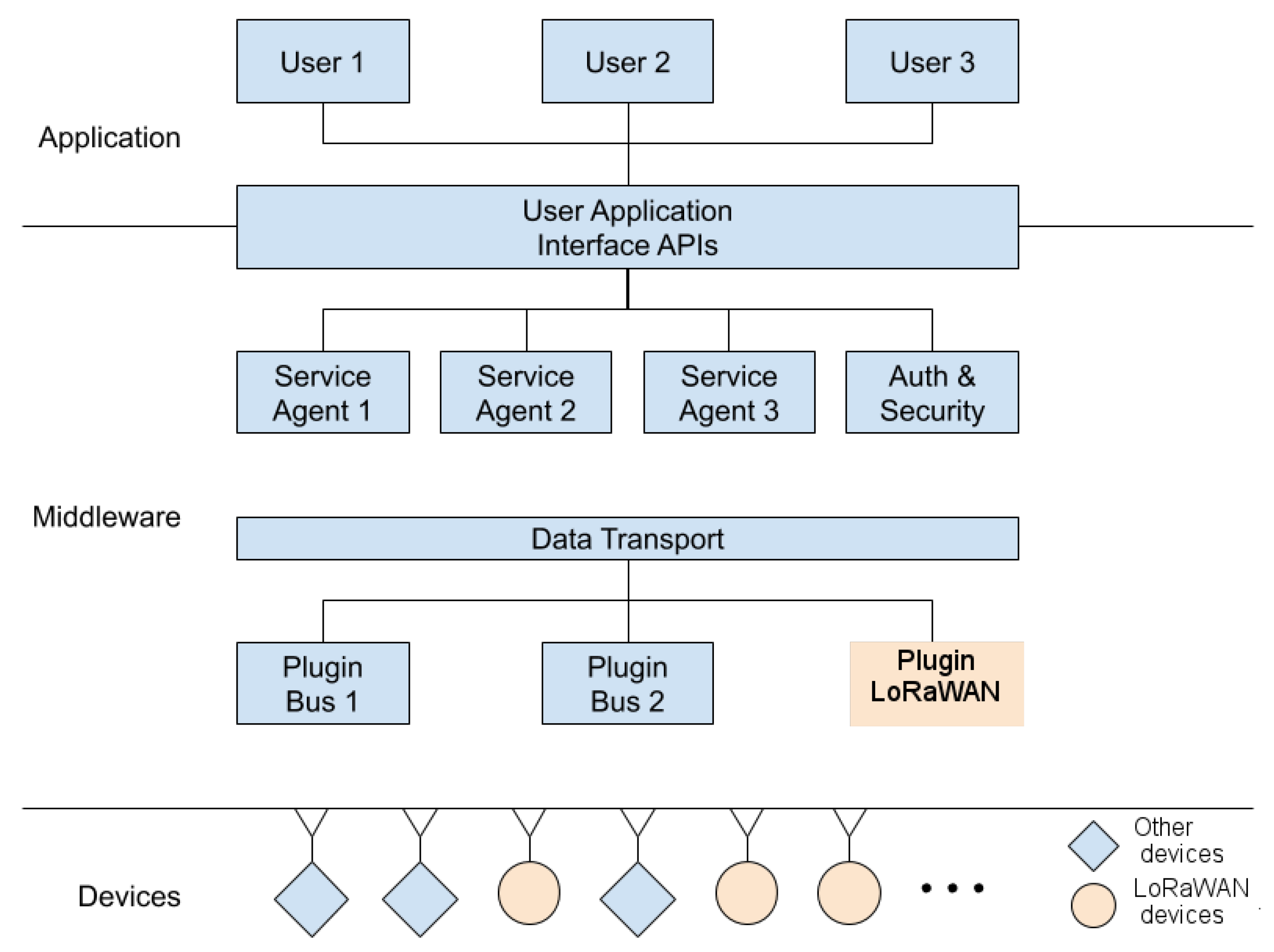
The proposed architecture provides multi protocol communication capabilities, such as described in the following. The devices communicate with the middleware based on a set of parameters, (including: the frequency of sensor data sending, the information model, the data encryption, how they manage the network connection state, how they manage device memory and the data management reporting, how they compute performance indices). The functions that are called (in the device) by the middleware to perform an action can also be defined as a parameter. The middleware provides services for the devices and users, besides the logic and rules of the application. Among the services provided for the sensors are: authentication, authorization, date and time synchronization, measurements storage, data management storage, etc. The user services include: visualization of the facility state, which reflects the state of the devices in real-time in a pleasant and organized way, report generator, where measurement data can be plotted in interactive charts to be better analyzed, device management, acting interface where they can turn lights on and off, open and close gates, valves, etc., besides the basic ones authentication and authorization. The middleware is also responsible for interoperability and integration of multi-protocol devices and to serve the API for the applications and user interfaces.
The schematic representation of the proposed IoT architecture is shown in
Figure 3.
Integration with LoRaWAN
The integration of LoRaWAN with the proposed IoT architecture was implemented by using an open and easy-to-use solution: the LoRa Server project [
44].
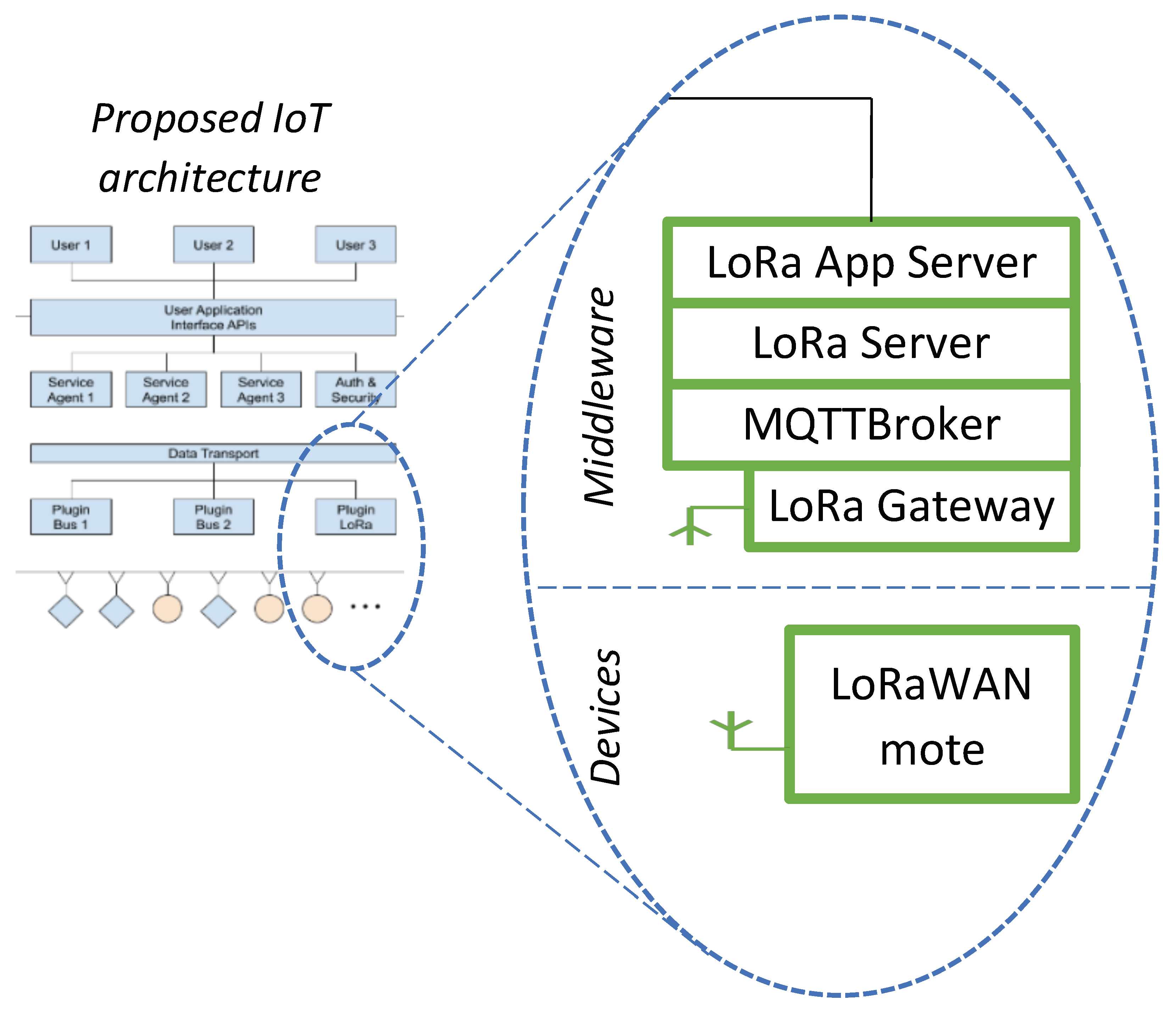
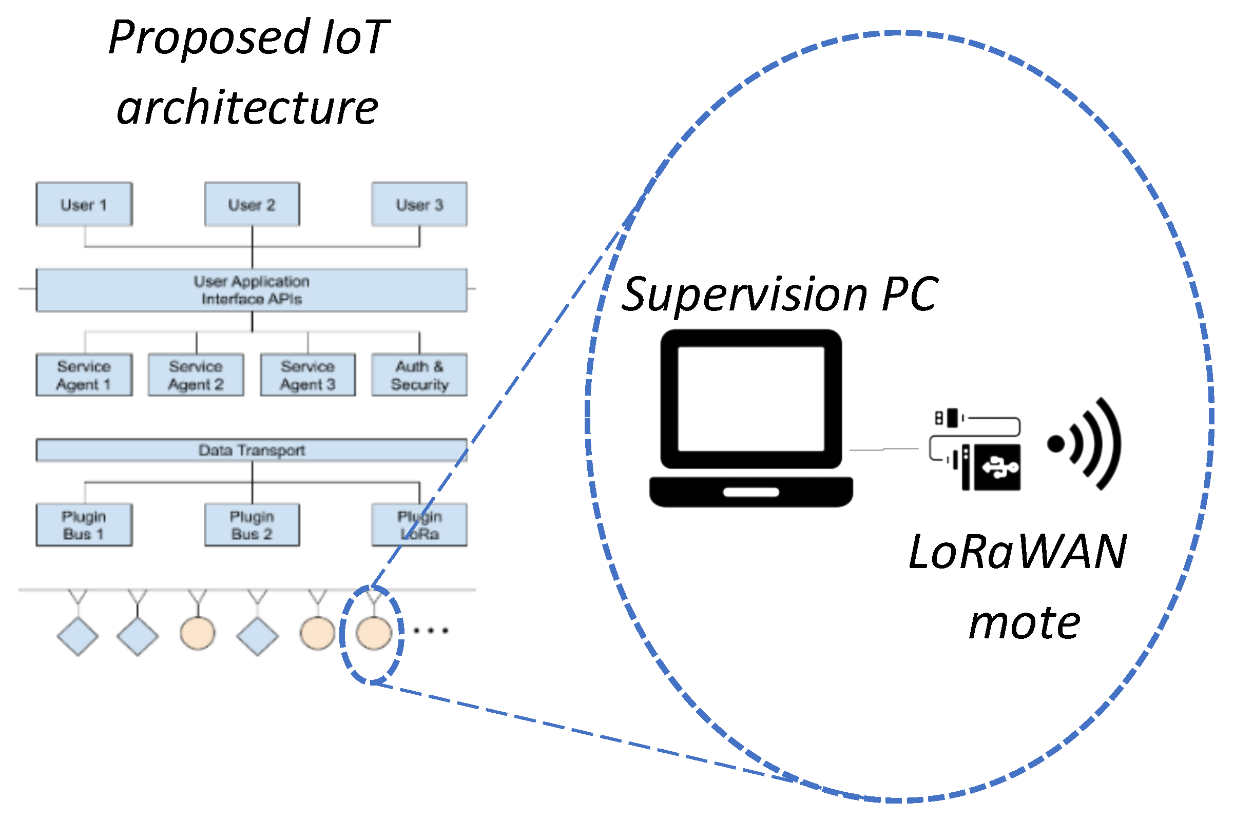
The LoRa Server project implements all the LoRaWAN stack and the set up can be done through a WEB interface. It has to be highlighted that within the LoRa Server Projects, the different LoRaWAN network components may have specific names which are different from the names used by the LoRaWAN standard. In particular, the LoRaWAN Network Server is called LoRa Server, the LoRaWAN Application Server is called LoRa App Server. The LoRa Server project has many possibilities for integration: via MQTT protocol; using cloud platforms (Google, AWS, Azure); by means of HTTP APIs; with direct access to databases, etc. In our case, we chose integration by means of HTTP API (i.e., the Lora App Server will make HTTP POST requests to the configured endpoints each time one events appear in the LoRaWAN network). The IoT architecture integrated with the LoRaWAN stack of the Lora Server project is shown in
Figure 4.
The LoRaWAN integration follows the generic integration rules of the IoT system and can also be replicated for different communication technology, in a natural way for the final user.
The LoRaWAN mote can be considered the origin of the measurement. The measurement is then sent, wirelessly, to the LoRa gateway, which is the entry point to the LoRa Server software architecture. Finally, via HTTP integration, information is forwarded the IoT middleware part, where is processed and stored for later analysis.
4. The Proposed Use Case: Data Model and Scalability Analysis
As stated in the introduction, to the best of the authors’ knowledge, the detailed definition of a use–case, and of the related data model, is missing in the literature. For this reason, the definition of all the information involved in the communication process and the required data throughput in a smart campus scenario is discussed.
4.1. The Smart Campus Use Case
In this subsection, the smart campus use case is detailed according to distributed control architecture described in
Section 2.1. From the point of view of the communication process, three different scenarios can be identified, for both the monitoring and the supervisory control functions: (i) the supervision of independent sensors, generators, and equipment, (ii) the coordination of local energy controllers, and (iii) the coordination of BEMS. In the proposed use case, only the scenario concerning independent sensors, generators, and equipment (including the related distributed controllers) will be considered, such as it represents the typical implementation of a LPWAN infrastructure integrating dispersed resources under the supervisory control of BEMSs or EMSs.
Different types of measuring instruments can be implemented in smart campus environments: from water and electrical power meters, to environmental sensors (e.g., for the measurement of room and ambient temperatures, volatile compound concentrations, solar irradiance, etc.), presence sensing devices, people counters, and many others. Concerning the amount of transferred information, electrical power meters are by far the most complex devices, by involving the measurement of several quantities, from energy flows, to power quality measurements. The reference set of information provided by such devices is reported in
Table 1, by considering the typical set of measurements provided by a smart meter with a measuring full scale of 200 kVA.
As detailed in
Table 1, the maximum size of each set of information transferred by electrical power meters to the supervisory EMS or BEMS is equal to 37 B, and the related application level data throughput is on the order of 0.041 B/s, by assuming a monitoring time interval of 15 min. On the opposite, when simple sensors are considered (e.g., sensors involving the measurement of a single quantity), the monitored set of information can be noticeably reduced. In this case, such as reported in
Table 2, if we assume that a 16 bit value is adequate to represent any single measurement, the maximum size of each set of information is equal to 9 B, and the related data throughput is on the order of 0.01 B/s.
Concerning the transmission of information from the supervisory entity to independent sensors, the time information (synchronization) can be optionally requested by each sensor every 3 h (i.e., every twelve uplink messages), by using a confirmed LoRaWAN message. In this case a 8 B synchronization message (including the identification code of the sensor and the time reference) is sent by the EMS or the BEMS every 3 h, corresponding to a data throughput of about 0.00046 B/s.
When it comes to independent generators (i.e., power generators directly supervised by the smart campus EMS or by a single BEMS), the set of transferred information usually include the monitoring of energy flows, power quality measurements, such as well as specific operating parameters, and alarms. In
Table 3, the reference set of information provided by power generators is reported, by considering the case of a photovoltaic (PV) inverter, which is one of the most diffused power assets in distributed generation scenarios. In this case, the nominal power of the generator was assumed to be on the order of 200 kVA. As detailed in
Table 3, the maximum size of each set of information transferred by power generators to the supervisory entity is on the order of 30 B every 15 min, leading to an expected data throughput of about 0.033 B/s.
Concerning the transmission of information from the supervisory entity to independent generators, a set of control instructions is sent every 3 h, by using a confirmed LoRaWAN message (with the side benefit of not influencing the radio duty cycle of the gateway). The set of transferred information, such as detailed in
Table 4, includes the identification code of the device, the time reference signal (for synchronization purposes), an active power profile representing the power limitation request to the specific generator (with a time resolution of 15 min), and the initial timestamp of the job schedule. In this case a 36 B message is sent to each supervised generator by the EMS or the BEMS every 3 h, corresponding to a data throughput of about 0.003 B/s.
In
Table 5 the reference set of information provided by an independent equipment is reported, by considering the case of a HVAC system. In this case, such assuming that the monitored HVAC system is composed by a single device (e.g., a heat pump) with a nominal power consumption of 200 kVA, the maximum size of each set of information transferred by the system is on the order of 28 B every 15 min, leading to an expected data throughput of about 0.031 B/s.
Finally, concerning the transmission of information from supervisory entities to independent equipment, a more generalized scenario can be considered, i.e., by considering the provisioning of job schedules to single controllers, such as smart thermostats, smart plugs, or other simple equipment controllers. From the communication point of view, those devices can behave both as single sensors and as controllers. Acting as sensors, they communicate the state of the related controlled parameter (e.g., the room temperature) every 15 min, according to the data model described in
Table 2. Acting as controllers, they receive a set of control instructions (e.g., room temperature set-points) every 3 h, by using a confirmed LoRaWAN message. As detailed in
Table 6, the set of control instructions includes: the identification code of the device, the time reference signal (for synchronization purposes), a set-point profile (with a time resolution of 15 min), and the initial timestamp of the job schedule. Assuming that a 16 bit register is adequate for representing any possible set-point value, a 36 B message is sent to each smart controller every 3 h, with a corresponding data throughput of about 0.003 B/s.
4.2. Application Example
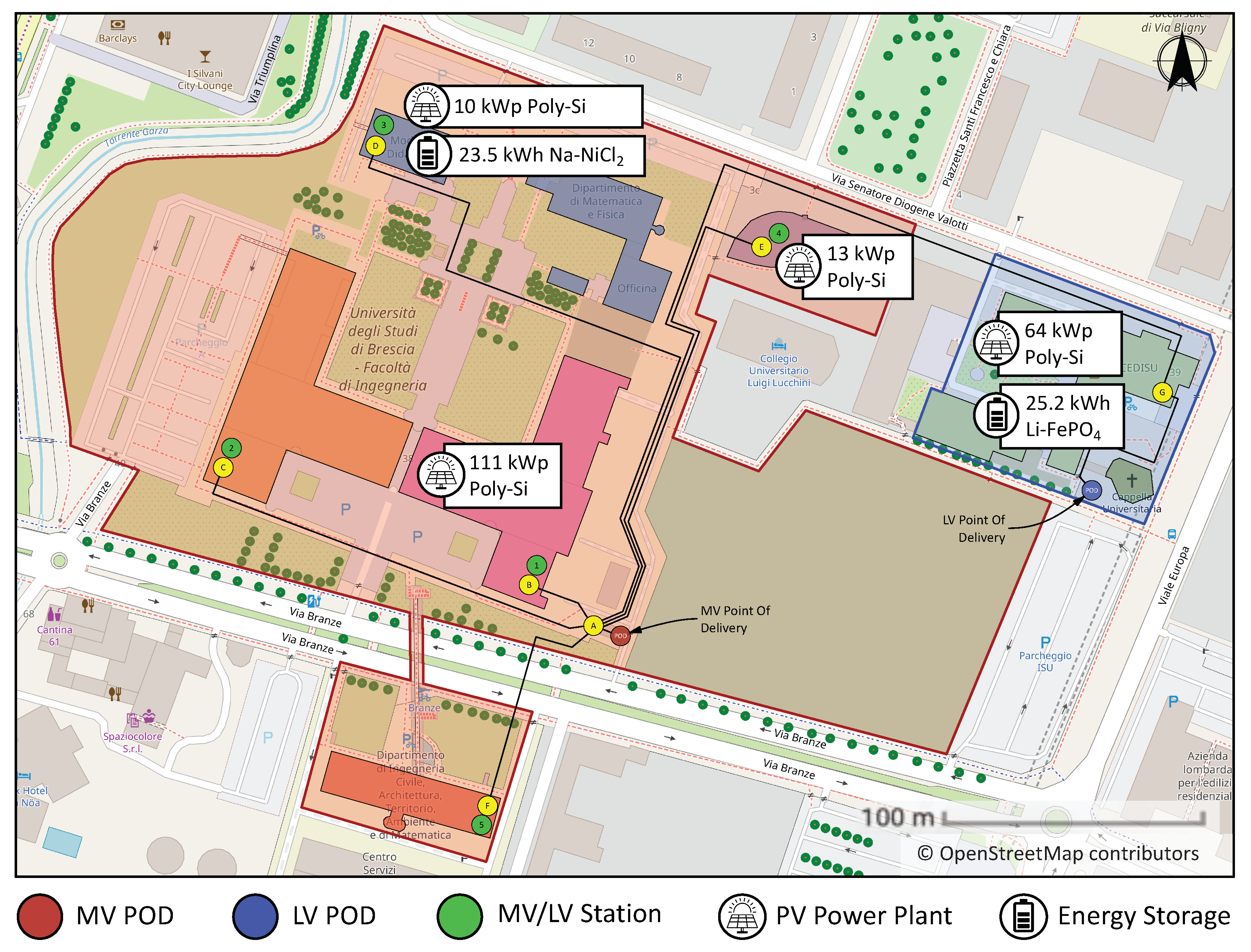
In this subsection an example of the application of the proposed LoRaWAN architecture for the monitoring of distributed energy resources in a real smart campus scenario is presented. The proposed communication architecture has been implemented for the monitoring of the operation and efficiency of a photovoltaic system installed in the engineering campus of the University of Brescia, Italy, such as part of the experimental activities of eLUX laboratory (
https://elux.unibs.it/). The eLUX laboratory is a living lab for research, training, and services on smart-grids, smart-living and electric vehicles within the Engineering Campus of the University of Brescia. Further details on the assets and experiments of the laboratory can be found in [
45].
As shown in the map depicted in
Figure 5, the engineering campus of the University of Brescia has two points of common coupling with the distribution grid. The area highlighted in red in the map is fed by a Medium Voltage (MV) line of distribution network, while the area highlighted in blue is fed by a Low Voltage (LV) line. As shown in the map, the campus is equipped with four photovoltaic (PV) power plants (with a nominal power ranging from 10 to 111 kWp each) and two electrical storage systems (EESs).
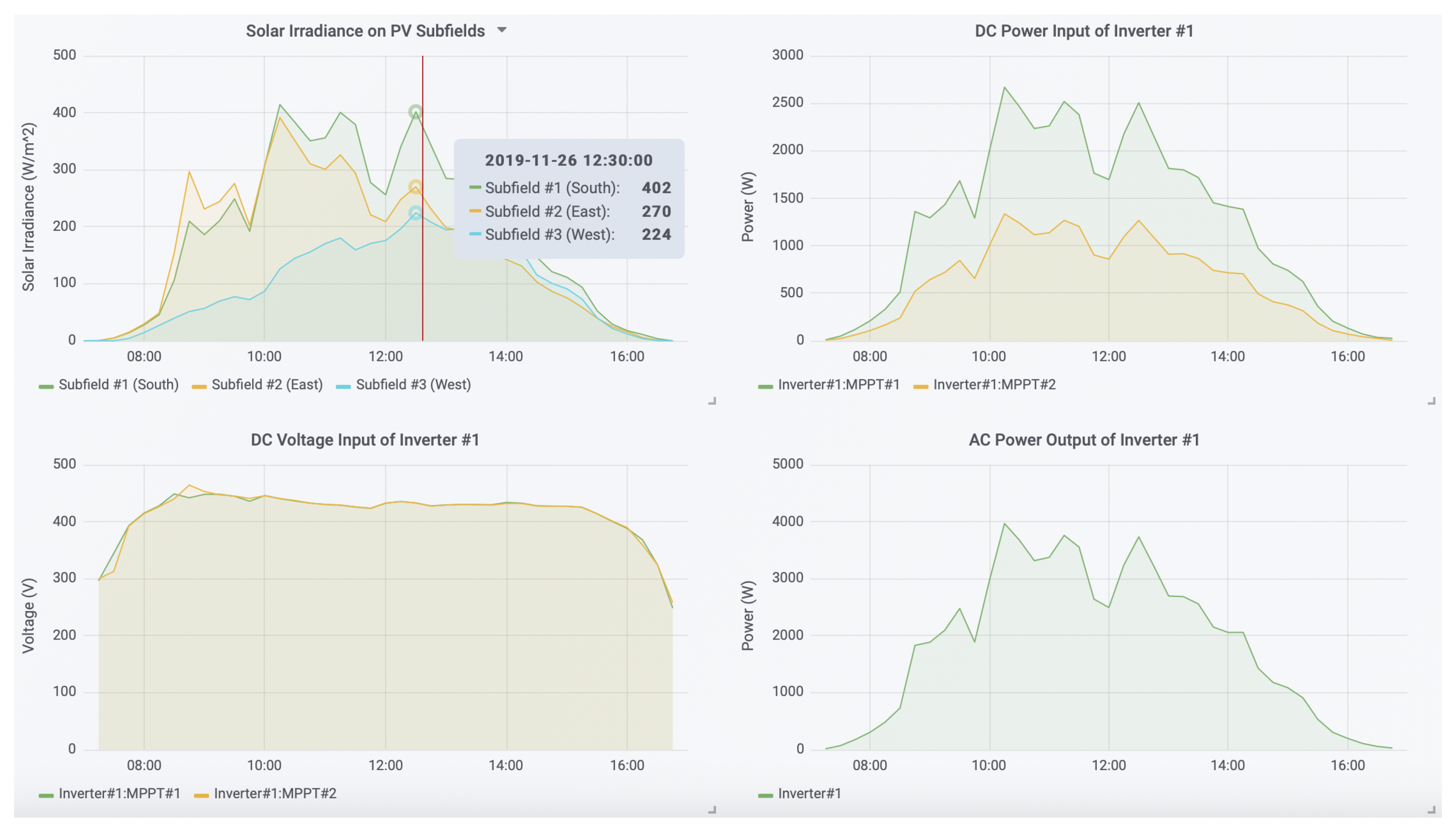
The monitoring of the working parameters of all the installed equipment, such as well of additional field sensors (such as solar irradiance meters) is crucial for the performance analysis and maintenance of such energy assets. In particular, the monitoring of single components may be not sufficient for monitoring the proper operation of equipment, and the combined analysis of different parameters may be required. This is the case, for instance, of the analysis of the operation of PV inverters, where the combined monitoring of the working parameters of the inverter and of the solar irradiance on the PV strings connected to the inverter are essential to properly interpret the correct behavior of the equipment. The power output of the inverter, in fact, strictly depends on the power input provided by the PV strings, which is determined by the amount of solar irradiance collected by the PV modules forming the strings. By using these data, the efficiency of the PV inverter can be determined by computing the ratio between the power input and output, respectively. Conversely, potential malfunctioning of PV modules can be detected by computing the overall efficiency of the PV strings, i.e., by computing the ratio between the power input at the inverter and the total solar radiation on the PV strings (which is equal to the amount of measured solar irradiance multiplied by the total surface of the array of strings). Other relevant information on the health of the system and equipment can be also derived by the analysis of the Maximum Power Point (MPP) voltage inputs, compared with the amount of measured solar irradiance.
The supervisory monitoring of the PV inverters installed on 64 kW PV systems of the engineering campus of the University of Brescia is here proposed as example of the application of the proposed LoRaWAN architecture. The PV system is installed on the main building located on the north-east area of the campus, and connected to the LV public distribution grid. The PV array of the system is formed by 279 modules (model Trina Solar, TSM-230PC05), subdivided in 18 PV strings. The PV strings of the system are installed on three different pitches of the four stories building, with 91 modules facing South, 68 modules facing West, and 120 modules facing East. Three different solar irradiance sensors (model Si-RS485TC-T) are installed on each pitch. The PV strings are connected to six PV inverters (model ABB Power-One Aurora PVI-12.5-OUTD-FS-IT), which form the power conversion stage of the PV system. Each inverter is equipped with two separated Maximum Power Point Trackers (MPPTs), each connected to a single string and to a parallel of strings, respectively, to balance PV array input of the power conversion stage. While the solar irradiance sensors are installed on the roof of the building, the PV inverters are installed in the electrical equipment room located in the basement of the building. It is worth to note that in both the mentioned locations (i.e., the roof and the basement) the WiFi infrastructure implemented inside the building facilities is not available.
To allow the communication between the installed equipment and the main infrastructure of the building by using the proposed LoRaWAN architecture, the following experimental setup was deployed. Each of the solar irradiance sensors installed on the roof of the building was connected to a Raspberry Pi 3 device by means of a RS485 bus, and the data acquired by implementing the Modbus RTU protocol. Similarly, each of the PV inverter, communicating by using the proprietary Aurora protocol, was connected to an intelligent device (ABB PVI-RS485-MODBUS Converter), responsible for the conversion between the proprietary protocol and the Modbus RTU protocol. The latter was then connected to a Raspberry Pi 3 by means of a RS485 bus, and the data acquired by implementing the Modbus RTU protocol. Finally, each of the installed Raspberry Pi 3 was interconnected with a RN2483 LoRaWAN module. Examples of data collected by using the described LoRaWAN architecture are reported in
Figure 6.
4.3. Scalability Analysis
Some simple analyses can be carried out to estimate the scalability of the proposed LPWAN infrastructure, by computing the maximum value of devices that can be managed by a single LoRaWAN base station. Referring to the data exchange procedure described above, from 9 B to 37 B messages are transmitted by field devices to supervisory entities every 15 min. Similarly, during downlink transmissions, 8 B to 36 B messages are exchanged every 3 h. If the additional 13 B required by the LoRaWAN headers and trailers are taken into account, the maximum uplink message is 50 B long, whereas the maximum downlink message is 49 B long. Alternatively, if we consider a more realistic scenario with a mixed set of simple sensors and complex devices, the average uplink message is 39 B long, and the average downlink message is 35 B long. Finally, if we consider the sum of the maximum uplink and downlink messages, including the LoRaWAN headers and trailers, about 649 B are exchanged every 3 h, leading to a maximum data throughput of 0.06 B/s, which means that the duty-cycle limitation of LoRaWAN is always satisfied.
In the following, the theoretical capacity of a single LoRaWAN base station is computed for the two presented scenarios, i.e., by considering that each installed device operates with the maximum expected payload (both at uplink and downlink), and by considering a mixed set of simple sensors and complex devices, each of them operating with the expected average uplink and downlink payload. In both the cases, the theoretical capacity of a single LoRaWAN base station is computed by assuming that every 3 h each cell must be able to manage up to twelve uplink messages with a length from 39 B to 50 B each (corresponding to the two considered scenarios), and one downlink message (with a length from 35 B to 49 B), per each served node, including the LoRaWAN headers and trailers. In this study, three different channels have been taken into account by varying the Spreading Factor (SF) from 7 to 12. The computed capacity of each LoRa base station is reported in
Table 7 and
Table 8, for the worst-case scenario (i.e., corresponding to the maximum expected payload) and for a realistic scenario (i.e., corresponding to the average expected payload), respectively.
Under perfect synchronization, the number of motes is given by
, where
T is the considered refresh period (i.e., 3 h), and
is sum of the message over-the-air time duration per each node over
T. If we consider that the actual throughput of ALOHA access is about 18% of the synchronized scenario [
46], the maximum number of devices that can be managed by a single LoRaWAN base station is on the order of 3295 and 3919 devices per channel, for the worst-case and the realistic scenarios, respectively, which correspond to about 9885 and 11,757 devices per cell, when the three compulsory channels are adopted.

 ,
, 


