Time-Varying Dynamic Analysis of a Helical-Geared Rotor-Bearing System with Three-Dimensional Motion Due to Shaft Deformation


Department of Aeronautical and Mechanical Engineering, Air Force Academy, Kaohsiung 820, Taiwan
Appl. Sci. 2020, 10(4), 1542; https://0-doi-org.brum.beds.ac.uk/10.3390/app10041542
Submission received: 24 December 2019
/
Revised: 7 February 2020
/
Accepted: 20 February 2020
/
Published: 24 February 2020
(This article belongs to the Special Issue Selected Papers from IMETI 2018)
Abstract
:The rotordynamics of a helical-geared rotor-bearing system were investigated. A new dynamic model for a helical-geared rotor-bearing system, which takes into account three-dimensional (3-D) motion due to rotating shaft deformation, was proposed. The proposed model considers the time-varying effect, which in other models, is considered constant. The system equations of motion were obtained by applying Lagrange’s equation, and the dynamic responses were computed by the fourth-order Runge–Kutta method. The time-varying dynamic responses of the helix angle, transverse pressure angle, gear pair center distance, and total contact ratio were investigated. The numerical results show that the time-varying effect is an important factor in gear vibration analysis and cannot be neglected when the helical geared rotor-bearing system has a lower stiffness.
1. Introduction
The gear system is one of the most important transmission mechanisms and is commonly used in gas turbines, automotives, generators, electrical products, and aerospace applications. The geared rotor system is the main source of vibration problems in power transmission systems. Rotor dynamics analysis is extremely important in the above-mentioned fields of application involving the design of vibrating machinery. Therefore, a more realistic dynamic model of the helical-geared rotor-bearing system for prediction of the vibration response is necessary.
Many researchers have analyzed the dynamics of the gear pair system. Lalanne and Ferraris [1] predicted the dynamic behavior of rotors in bending and in torsion. They also discussed the influence of bending, and the possible instabilities were determined. Umezawa et al. [2] proposed a simulator which solves a differential equation with one degree of freedom in measuring the effects of the stiffness around tooth tip meshing, which facilitates deriving a profile of a spur gear that decreases vibration. Kahraman and Singh [3] used the harmonic balance method to develop a frequency response solution to the gear pair. Kahraman and Singh [4] also explored the nonlinear correlation between the radial clearance and the backlash between the spur gear pair in radial rolling bearing. They assumed that the gear meshing stiffness is linear and does not change with time. Huang and Liu [5] simulated the spur gear teeth action with a variable section Timoshenko beam. They subjected the gear pair to dynamic analysis with nonlinear contact stiffness.
Kahraman [6] developed a linear dynamic model of a helical gear pair which has been used to investigate the effects of the helix angle on the free and forced vibrational characteristics of the gear pair. Kubur et al. [7] proposed a dynamic model of a multi-shaft helical gear which could enable designers to predict the dynamic behavior of the system and provide the most advantageous configuration for optimal dynamic behavior. Zhang et al. [8] developed two-gear dynamic models, one with twelve degrees of freedom and the other with a multi-shaft geared rotor system. Bozca [9] investigated the helix angle effect on the helical gear-load carrying capacity. Both the overlap contact ratio and total contact ratio were calculated by changing the helix angle.
About forty years ago, a specific numerical calculation procedure, the finite element method (FEM), which provides more accurate modeling, was used for analyzing geared rotor-bearing systems. Nelson [10] used the Timoshenko beam theory and the finite element method to calculate the effect of shear deformation and rotatory inertia. Kahraman et al. [11] developed a finite element model of a spur-geared rotor system supported with flexible bearings. The model included the rotary inertia of shaft elements, flexibility and damping of bearings, material damping of shafts, and stiffness and damping of the gear mesh. However, their model did not consider the effect of the gear pair pressure angle. Shiau et al. [12] analyzed the coupled bending and torsional vibrations of geared rotors as well as the effect of axial torque on bending vibrations. Choi and Mau [13] employed a transfer matrix model to determine the coupled bending–torsional natural frequencies and mode shapes of a spur-geared rotor-bearing system. Steady-state responses due to excitation of mass imbalance, geometric eccentricity, and gear mesh transmission error were also investigated. Chen [14] discussed the dynamic responses of a double-stage geared rotor-bearing system with translational motion due to the rotating shaft deformation. The proposed model considers contact ratio and pressure angle of the gear pair as time-dependent variables, whereas in other models, they are constants. Prabel [15] investigated the application of time integration methods to rotor-stator assembly modeled. Both the average acceleration method and the central differences method were used to discuss numerical instability.
Gears have been widely used in industrial applications over the years, taking into account that time-varying variables or time-varying gear mesh stiffness could improve gear system accuracy. Ozguven and Houser [16] approximated time-varying mesh stiffness by using a constant mesh stiffness with a transmission error excitation. Kim et al. [17] developed a new dynamic model of the spur gear pair which considered the pressure angle and contact ratio as time-varying. Saxena et al. [18] discussed the effect of the time-varying friction coefficient on the total effective mesh stiffness for the spur gear pair and indicated that the gear mesh stiffness changed due to the change in direction of the time-varying friction on both sides of the pitch line. A time-varying mesh stiffness model of the helical gear pair, including axial tooth torsional stiffness, tooth bending stiffness, and gear foundation stiffness, was developed by Wang et al. [19]. In an analysis of the spur gear pair dynamics system, Yi et al. [20] considered that both the pressure angle and the backlash change over time.
Although some nonlinear factors have been incorporated into the dynamic analysis of the gear system, few studies have considered the time-varying behavior in nonlinear dynamic modeling. There have been some studies on the time-varying meshing of the spur gear pair [18] and helical gear pair [19], the time-varying dynamic characteristics of the spur gear pair [17,20], and the spur-geared rotor-bearing system [14]. However, the dynamic characteristics of a helical-geared rotor-bearing system with time-varying effects have not been studied. In general, in nonlinear dynamic model analysis of the helical-geared rotor-bearing system, in order to facilitate modeling, previous studies have regarded the gear pair center distance, helix angle, and gear contact ratio as constants. In fact, when the gear pair has translational motion due to rotating shaft deformation, the center distance of the gear pair will change, which will then cause changes in the line of action, helix angle, and contact ratio. This study introduces a novel dynamic model for a helical-geared rotor-bearing system with 3-D (3-dimensional) motion due to rotating shaft deformation, which includes the time-varying dynamic characteristics of the helix angle, transverse pressure angle, gear pair center distance, and total contact ratio.
2. Dynamic Model of a Helical-Geared Rotor-Bearing System
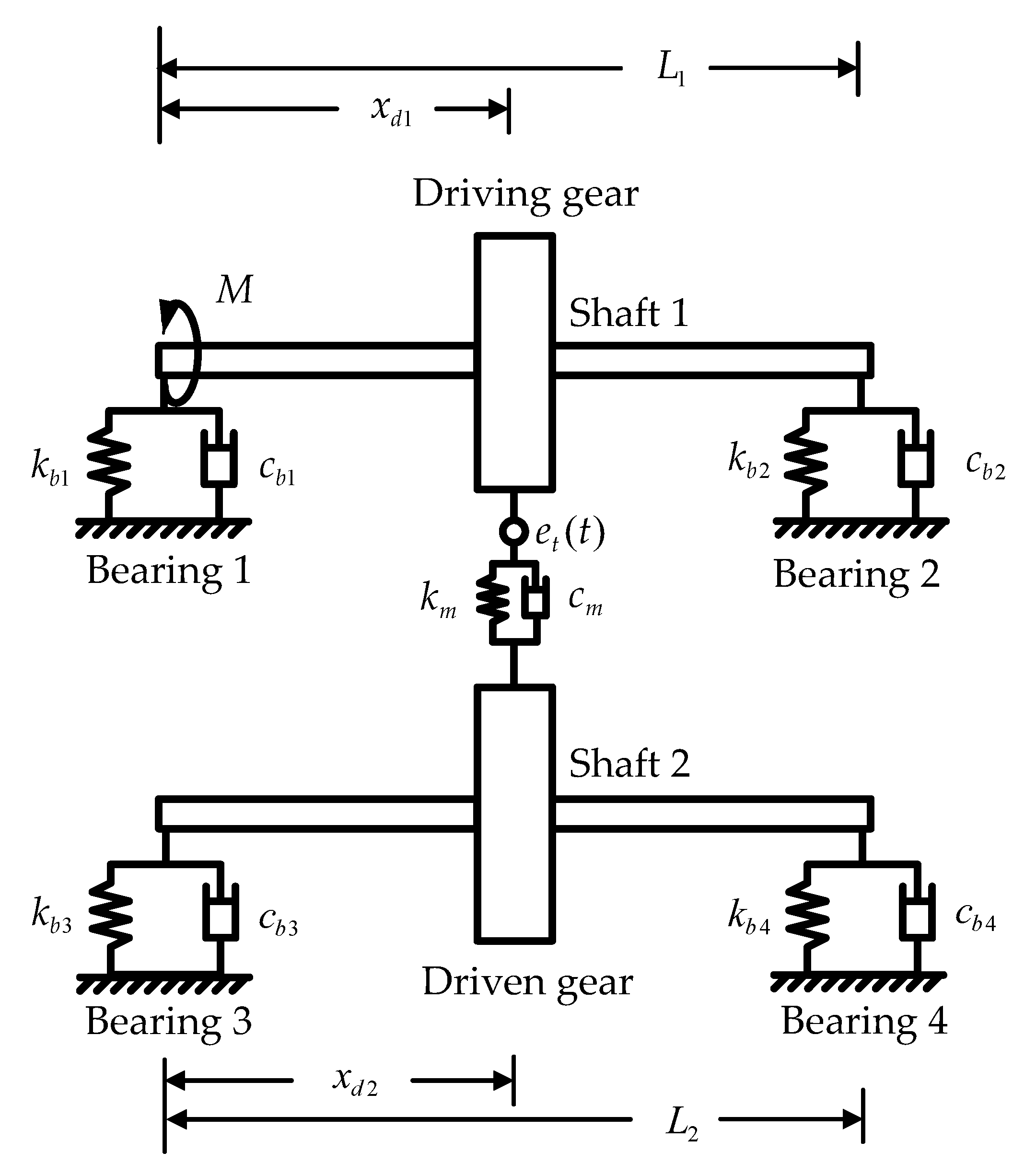
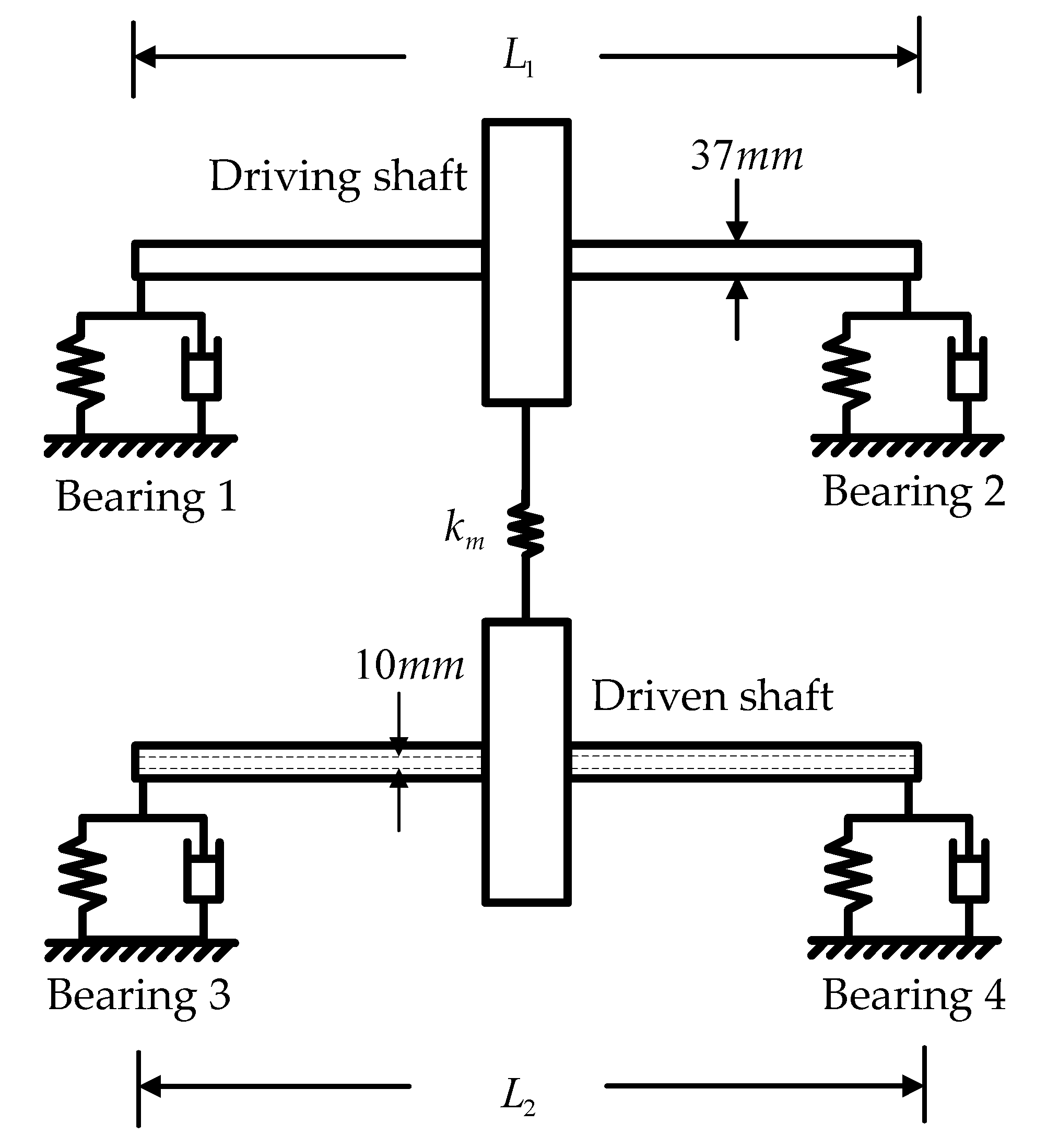
The schematic of a helical-geared rotor-bearing system is shown in Figure 1. Two uniform flexible shafts are of lengths L1 and L2. An external torque M is applied to shaft 1, and the gear pair is mounted on the shafts. The distances from gear to bearing are denoted as xd1 and xd2. The contacting mesh force is represented by the gear mesh stiffness coefficient km and damping coefficient cm along the pressure line. Four bearings are modeled as flexible elements with damping cbi and stiffness kbi.
2.1. Shaft
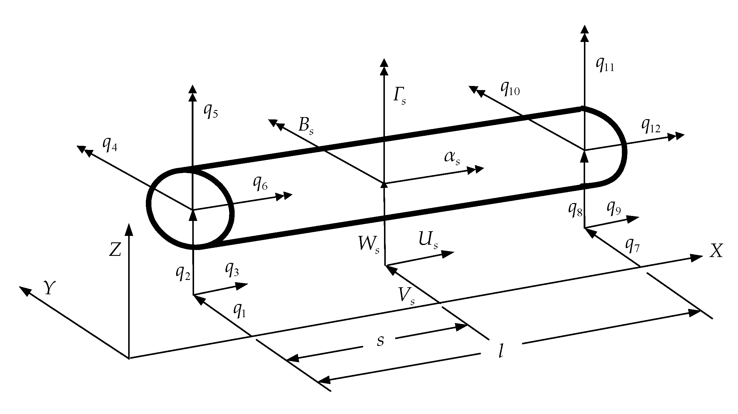
A two-noded element [12] was used to develop the model of the shafts presented in this paper. Six degrees of freedom (V, W, U, B, Γ, and α) are considered at each nodal point of the shaft and shown in Figure 2, where V and W are lateral displacements, B and Γ are the corresponding angular displacements, U is the axial displacement, and α is the corresponding angular displacement. The kinetic energy of the shaft including the axial and torsional motion is
where ρ, A, IsD, Ω, l, and IsP are the mass density, cross-section area, transverse moment of inertia, spin speed, element length, and polar moment of inertia of the shaft, respectively. The rotating shafts are modeled as Timoshenko beams and are considered to have shear and gyroscopic effects. The total potential energy of the shaft, including axial, bending, shear, and torsional deflection, is expressed as
where κ, E, and G are the shear factor, Young’s modulus, and shear modulus of the shaft, respectively. The equation of motion of the finite shaft element can be derived by substituting kinetic energy (1) and strain energy (2) into Lagrange’s equation:
where [Ms], [Gs], and [Ks] are the mass, gyroscopic, and stiffness matrices of the shaft element, respectively, and [Cs] = γ[Ks] where γ is the proportional damping coefficient. The details of these matrices are given in Shiau et al. [12].
2.2. Bearing Support
In the mechanical application of industrial use, the geared rotor system is generally supported with journal bearing. In this paper, it is recommended that the thrust bearing resists axial forces in a helical-geared rotor system. The four thrust-bearing supports are considered to be isotropic in the lateral direction. The potential energy and dissipation function, including the axial displacement effect of the thrust bearing support, can be expressed as:
The equation of motion of the thrust bearing can be derived by substituting strain energy (4) and dissipation function (5) into Lagrange’s equation:
where [Cb] and [Kb] are the damping and stiffness matrices of one bearing, and
2.3. Disk and Helical Gear Pair
In this paper, the gear pair is assumed to be two rigid disks. The kinetic energy including the axial motion of each disk can be expressed as follows:
where md, IdD, and IdP are the mass, transverse mass moment of inertia, and polar mass moment of inertia of the disk, respectively. The equation of motion of each disk can be derived as:
where
and [Md] and [Gd] are the respective mass and gyroscopic matrices of one gear, and {Fd} is the force vector due to disk eccentricity.
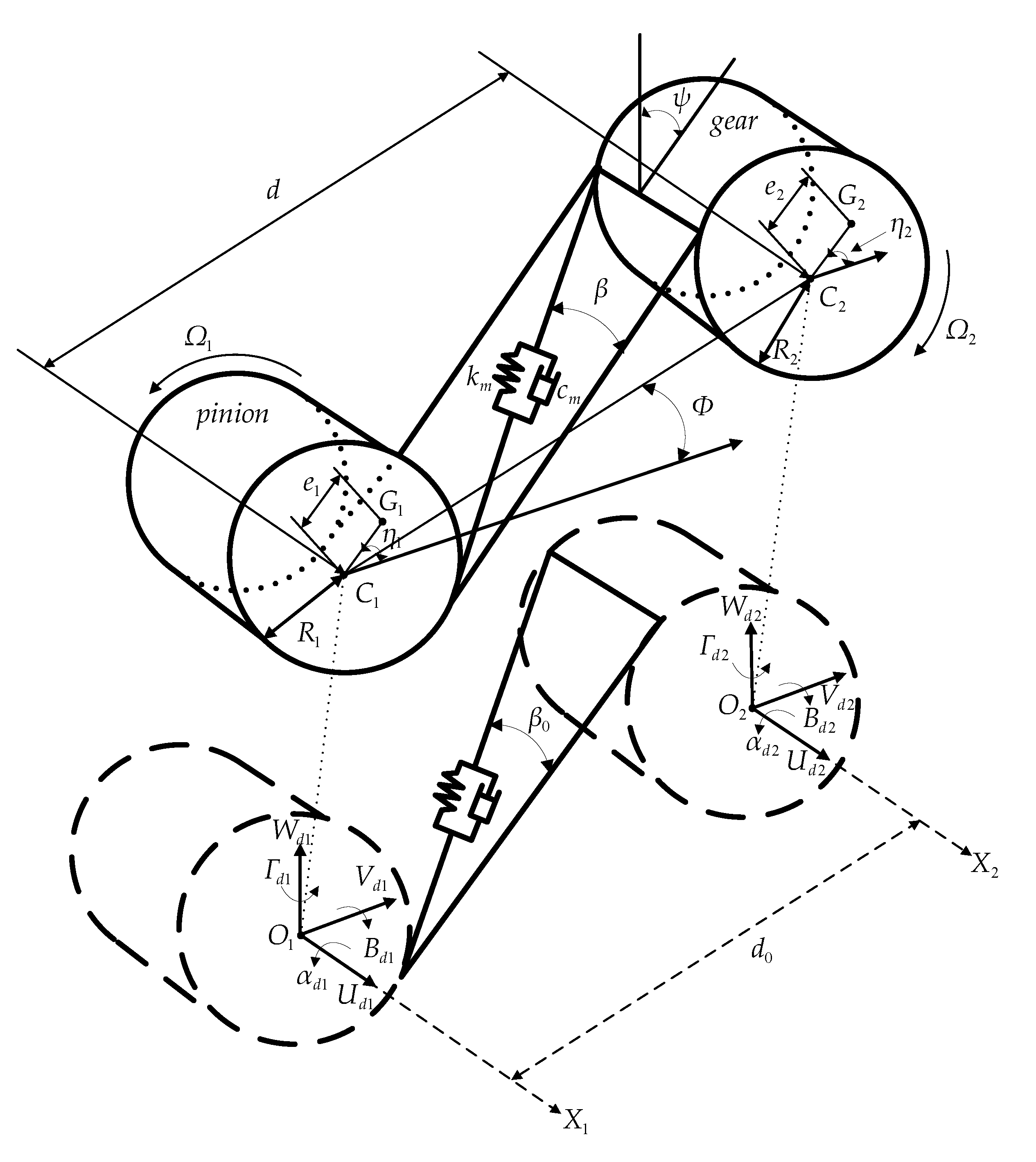
Figure 3 describes a helical gear dynamic model with 12 generalized coordinates. O1 and O2 are the gear centers when the rotating shafts have no deformation; d0 is the initial gear pair center distance; β0 is the initial helix angle of the gear pair. In most previous studies [1,2,3,4,5,6,7,8,9,10,11,12,13,15,16], these values are regarded as constant when they are time-independent. Generally, the gear centers will change with time due to the vibration of the rotating shafts. The gear centers can move to C1 and C2. G1 and G2 are the mass centers of the pinion and gear, respectively. Due to the vibrations of the rotating shafts, the centers of the gear and pinion would shift, and displacements (Vd, Wd, Ud, Bd, Γd, and αd) would change with time. This makes the center distance, helix angle, transverse pressure angle, relative position angle, contact ratio, and the relative displacement of the gear pair vary with time. In other words, due to the time-varying motions of pinion and gear, the gear pair center distance and the helix angle are time-dependent; therefore, the gear pair center distance is changed from d0 to d and expressed as
Similarly, the helix angle is changed from β0 to β(t), which is represented as
where pz is the lead of the helical gear pair. Ω1 and Ω2 are the rotating speeds of the pinion and the gear, respectively. The transverse geometrical eccentricities are denoted by e1 and e2. η1 and η2 are the transverse eccentricity angles of the transverse plane. The gear mesh force along the pressure line can be expressed as:
The damping coefficient cm is assumed to be zero. The gear mesh stiffness is accounted for by transverse tooth bending stiffness, transverse tooth shear stiffness, transverse tooth radial compressive stiffness, transverse gear foundation stiffness, Hertzian contact stiffness, axial tooth bending stiffness, axial tooth torsional stiffness, and axial gear foundation stiffness. The gear mesh stiffness is assumed as a periodic function of the mesh period. In the mesh situation, there are three teeth contacts and two teeth contacts, and the gear mesh stiffness will be different. The details of the gear mesh stiffness are shown in Wang et al. [19]. The relative displacement of the gear mesh in a direction perpendicular to contact surfaces is represented by δ(t) and defined as follows
where R1 and R2 are the radii of base circles for the pinion and the gear, respectively. ψ(t) is the angle between the plane of action and the positive y-axis and is defined as:
where ϕ(t) is the transverse pressure angle of the gear pair and is expressed as:
Φ(t) is the relative position angle of the gear pair. It is between the line connecting the center of the gear pair and the positive x-axis and is defined as:
According to the definition of the total contact ratio for a helical gear pair, the time-varying motions of the rotating shafts will also lead to changes in the contact ratio. The total contact ratio [9] becomes time-varying and can be expressed as:
where A1 and A2 are the radius of the addendum circles for the driving gear and driven gear, and pt and b are the transverse circular pitch and face width, respectively.
The corresponding equation of motion of the helical gear pair can be expressed as:
where [Md1] and [Md2] are mass matrices of driving and driven gears, and [Gd1] and [Gd2] are gyroscopic matrices. Nt1 and Nt2 are the teeth number of driving and driven gears. [Sh] is the stiffness term due to the gear mesh effect. {Fd} is the force vector due to disk eccentricity.
2.4. System Equation of Motion
Equations (3), (6), and (21) can be combined for the entire helical-geared rotor-bearing system, as follows:
where [Mss], [Gss], [Css], [Kss], {Fss}, and {qss} represent the system mass matrix, gyroscopic effect matrix, damping matrix, stiffness matrix, force vector, and displacement vector, respectively.
3. Validation and Numerical Analysis
3.1. Dynamic Model Validation
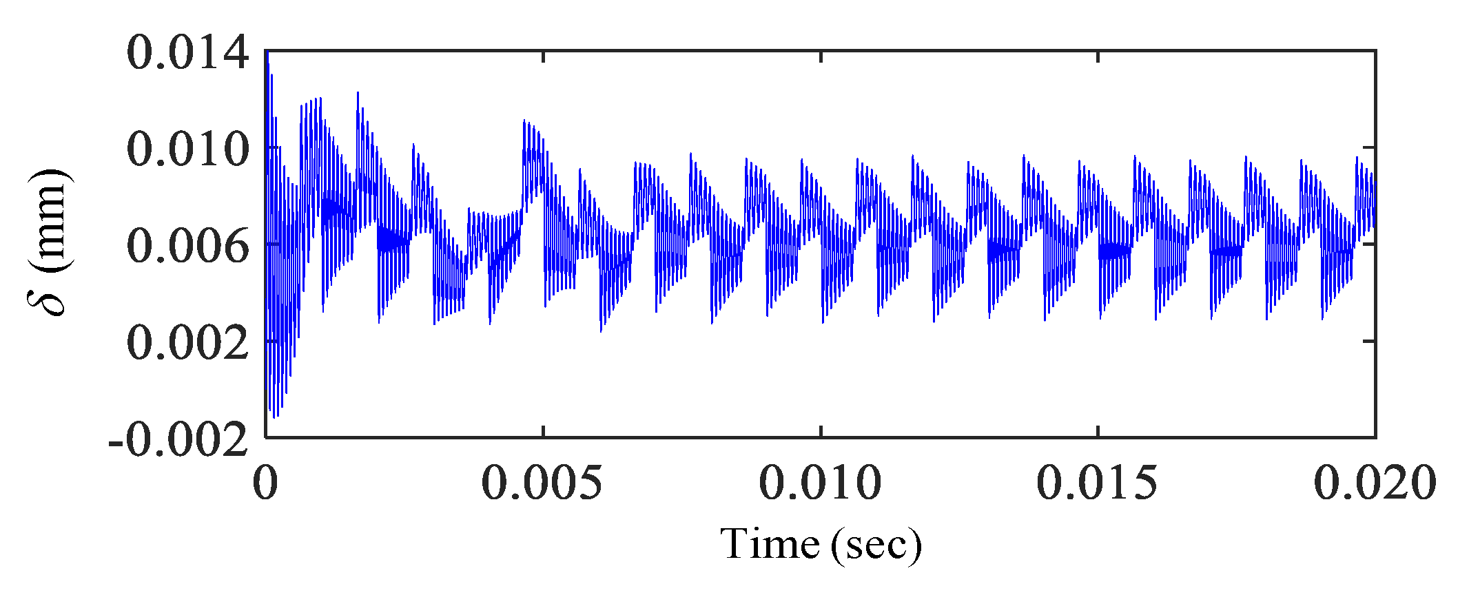
In order to verify the accuracy of the proposed model, I chose two cases for verification. In case 1, Kim et al.’s [14] time-varying spur gear pair system was applied to the time-varying validation. The material parameters are shown in Table 1. All the responses in this study were computed by the fourth-order Runge–Kutta method, and the time step size was selected as Δt = 10−9 sec. As can be seen from Figure 4, the time responses obtained from the proposed model are similar to Kim et al.’s [17] results. The amplitude and the periodic of the time responses are accurate. In case 2, Zhang et al.’s [8] spur-geared rotor-bearing system was applied to validate the correctness of the geared rotor-bearing model. The spur-geared rotor-bearing system is shown in Figure 5, and Zhang et al.’s [8] values for the system parameters are listed in Table 2. Both the results presented here and by Zhang et al. [8] of the natural frequencies and corresponding mode shapes are listed in Table 3 for comparison. It is shown that the maximum relative error is less than 0.8 percent. This means that the results of this study are in good agreement with those of Zhang et al. [8].
In summary, the proposed new model is effective for the time-varying spur gear pair and the geared rotor-bearing system.
3.2. Time-Varying Effect of the Helical-Geared Rotor-Bearing System
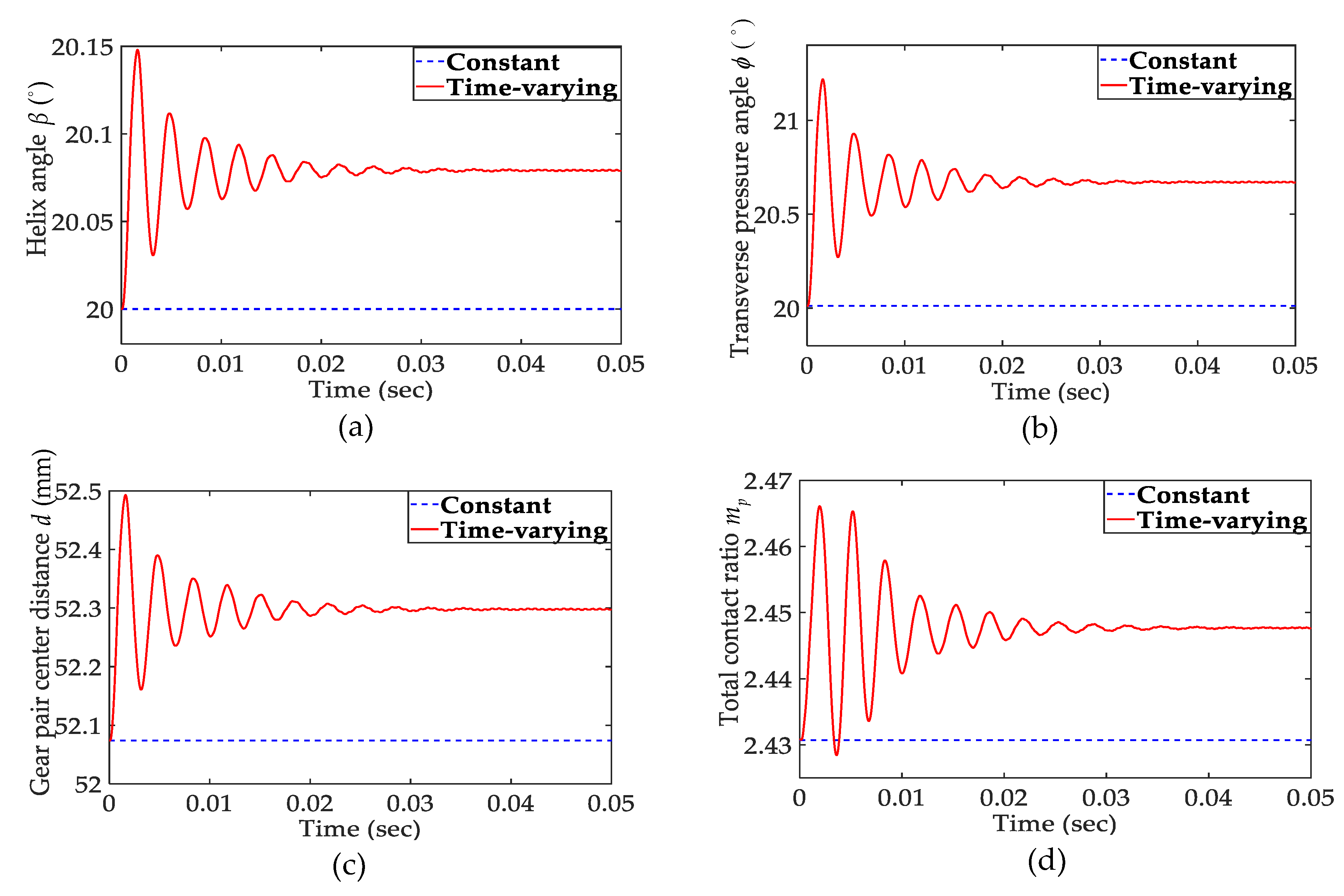
Although many dynamic models for the helical-geared rotor-bearing system have been presented, no researchers have simultaneously considered the time-varying effect due to rotating shaft deformation in their dynamic models. In order to simplify the dynamic model of the helical gear system, the previous models considered the helix angle, gear pair center distance, and contact ratio as constant values. The results that simulate a gear pair system by using constant dynamic characteristic values are usually rough and impractical. This section presents the results of time-varying numerical simulations for a helical-geared rotor-bearing system. This time-varying effect can lead to different dynamic characteristics, which in the previous models are usually ignored. The driving shaft was subjected to a fixed torque M = 500 N-m and Ω1 = 3000 rpm. Other parameter values given in Table 4 were used in the calculations for the helical-geared rotor-bearing system. In Figure 6, solid lines show the time-histories of the gear pair helix angle, transverse pressure angle, center distance, and total contact ratio. As shown in this figure, the fluctuation magnitudes of the helix angle are around 20.079 degrees, of the transverse pressure angle around 20.67 degrees, of the gear pair center distance around 52.298 mm, and of the total contact ratio around 2.4476. The dashed lines are the values when these dynamic characteristics are assumed to be constant. The difference values between the time-varying and constant conditions present the influence of the time-varying effect.
3.3. Time-Varying Effect of the Original Helix Angle
As can be seen in Figure 6, the difference value between the time-varying and the constant conditions is around 0.793 degrees for the helix angle, around 0.671 degrees for the transverse pressure angle, around 0.2243 mm for the gear pair center distance, and around 0.01696 for the total contact ratio. In this section, the difference values between the time-varying and the constant conditions under five different original helix angles are discussed. In the real helical gear systems, the range of helix angle is about 15–35 degrees. The results of the difference values are listed in Table 5. With the original helix angle raised, the difference values between the time-varying and the constant conditions of the helix angle, the transverse pressure angle, the gear pair center distance, and the total contact ratio are enhanced, especially the helix angle and total contact ratio. The time-varying variables have a greater effect on the higher initial helix angle and lower effect on the lower initial helix angle. This demonstrates that the time-varying variables of the higher initial helix angle are not negligible.
3.4. Time-Varying Effect of the Rotating Shaft Material and Outer Diameter
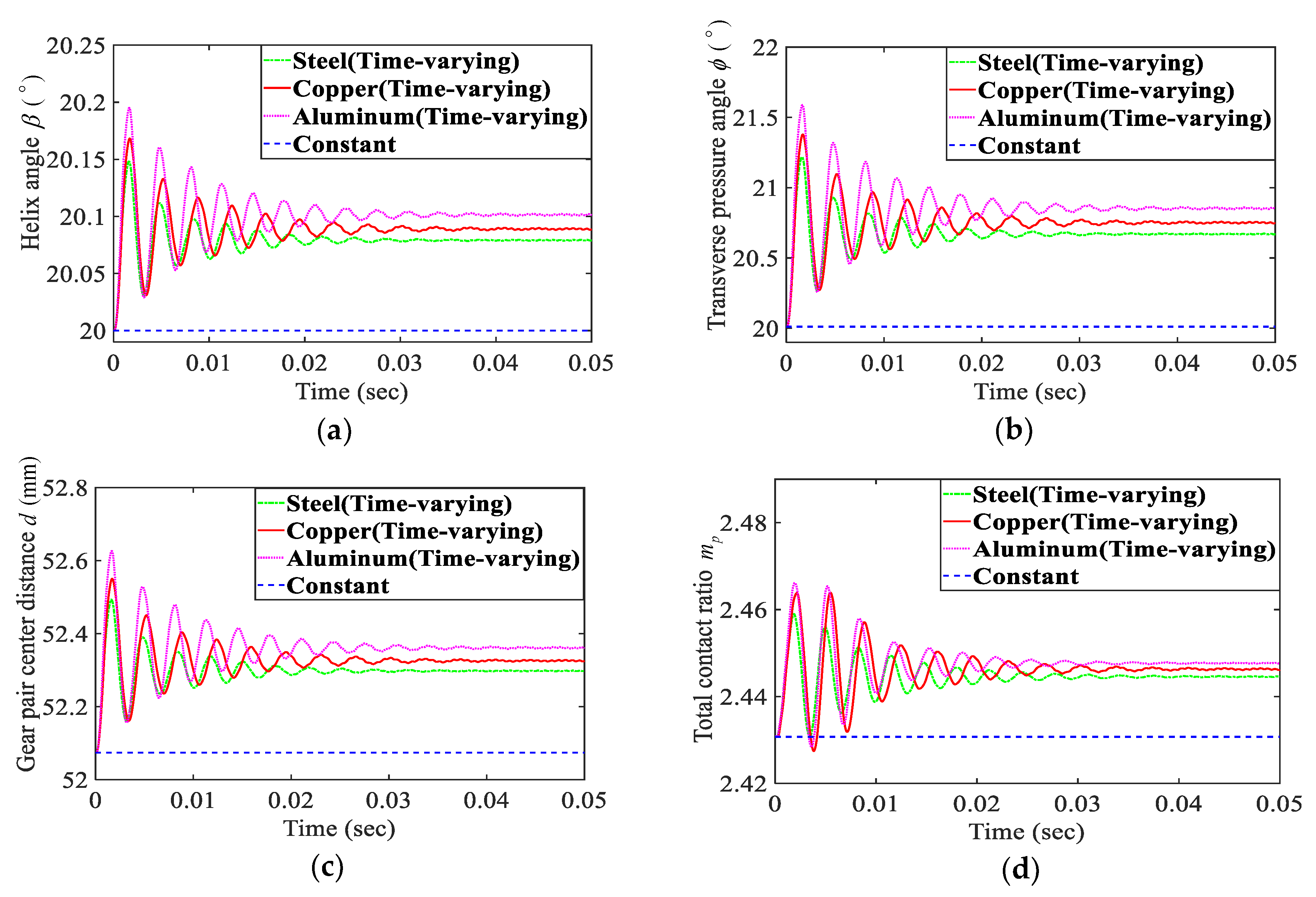
In order to analyze the time-varying effect with different rotating shaft materials, three cases of shaft material are discussed in this section. Case 1 is for steel, case 2 is for copper, and case 3 is for aluminum alloys. Table 6 lists the corresponding rotating shaft material parameters. Figure 7 presents the time histories for the helix angle, transverse pressure angle, gear pair center distance, and the total contact ratio. The difference values between the time-varying values with different rotating shaft materials and the constant values can be observed. If the rotating shaft is softer, the difference values between the time-varying values and the constant values are enhanced. This indicates that the time-varying effect has more influence on soft rotating shaft material than on hard rotating shaft material.
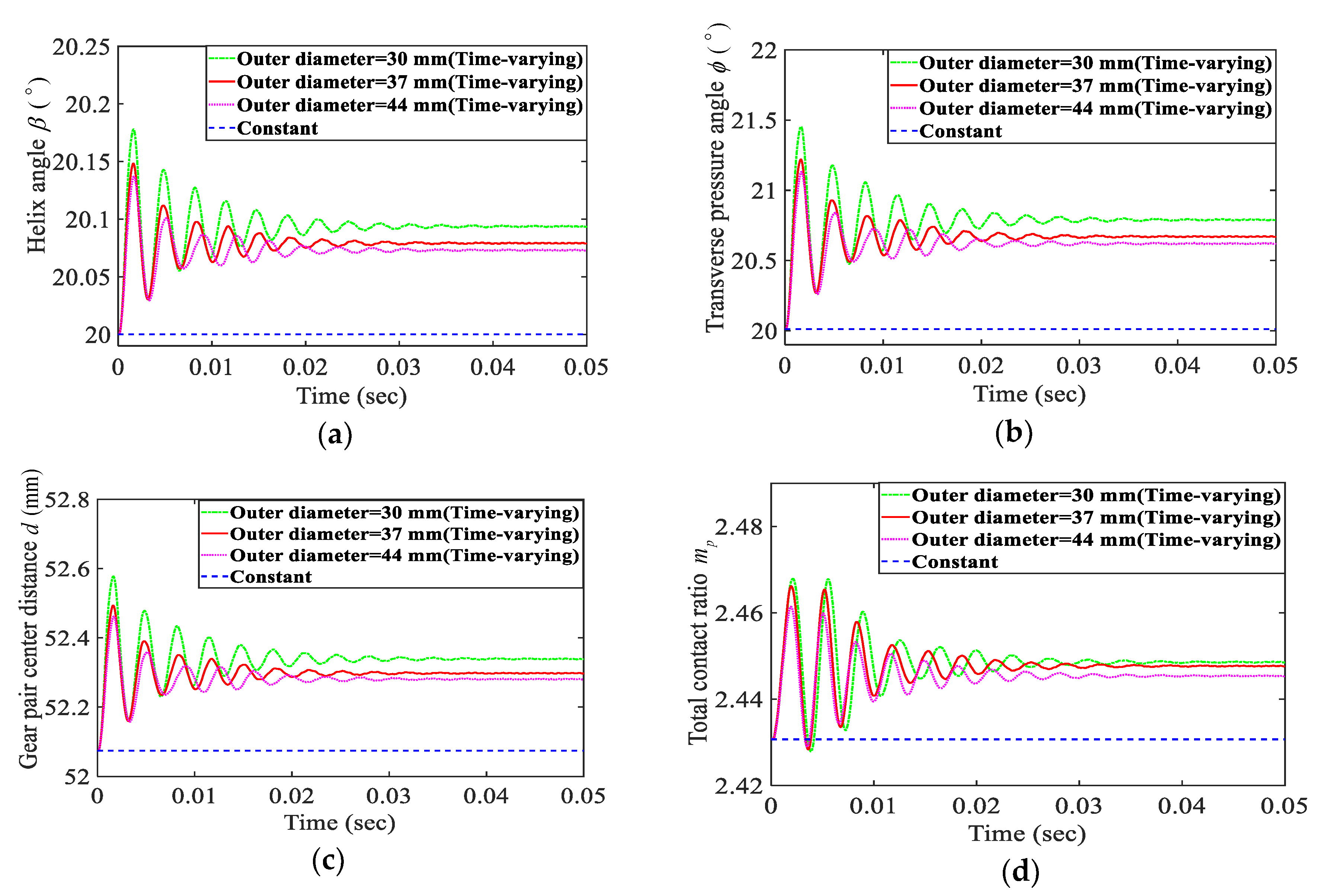
The same issues as Figure 7 under three different outer diameters of the shaft are obtained and shown in Figure 8. From Figure 8, it can be seen that the difference values between the time-varying values of these dynamic characteristics and the constant values are reduced with the outer diameter of the shaft enhanced. It may be noted that the time-varying effect has a more important effect on the thinner shaft.
3.5. Time-Varying Effect of the Bearing Stiffness
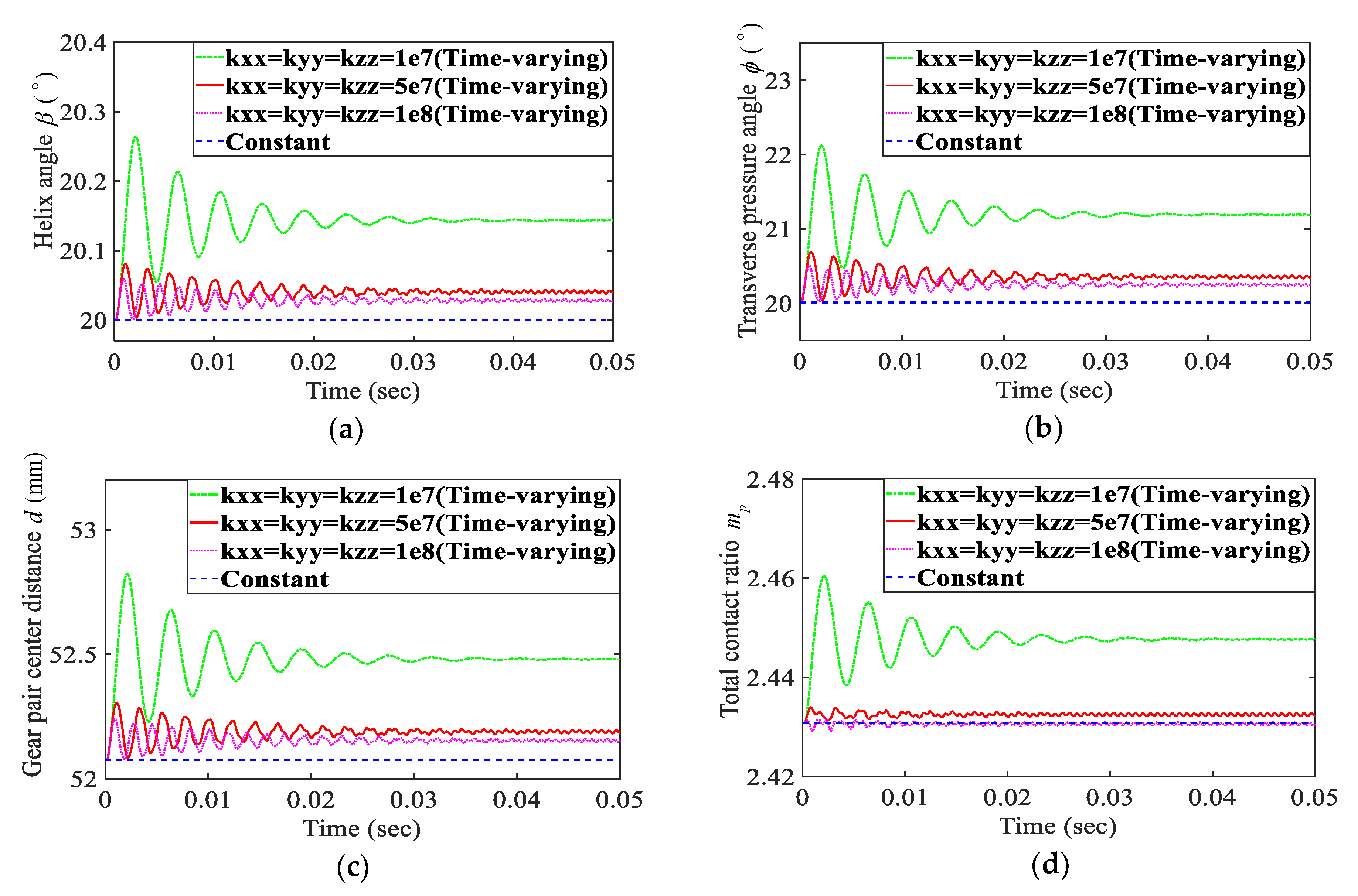
In order to analyze the bearing stiffness, three cases of bearing stiffness are discussed in this section. Case 1 is for bearing stiffness kxx = kyy = kzz = 1 × 10⁷ N/m, and cases 2 and 3 are kxx = kyy = kzz = 5 × 10⁷, 1 × 10⁸ N/m, respectively. Figure 9 shows the time-varying dynamic responses for the helix angle, transverse pressure angle, gear pair center distance, and total contact ratio. If the bearing stiffness is increased, the difference values between the time-varying values and the constant values are enhanced. The bearing stiffness is closely linked with the difference values between the time-varying values and the constant values of these dynamic characteristics. This means that the time-varying variables have a significant influence on the ordinary bearing stiffness, but have a small effect on the large bearing stiffness, especially for the total contact ratio.
As seen in Figure 7, Figure 8, Figure 9, it is interesting that the results of the dynamic characteristics of the helical-geared rotor-bearing system with time-varying variables are very different from those which are considered as constant when the rotating shaft is sufficiently soft, thinner, or the bearing stiffness is sufficiently small. This implies that the time-varying effect has a significant influence on the gear vibration analysis and cannot be ignored.
4. Conclusions
The proposed new model takes into account the time-varying helix angle, the transverse pressure angle, the gear pair center distance, and the contact ratio. The model consists of finite element shafts with a helical gear pair and thrust bearing. The Lagrange method was used to derive the equations of the motion of the system, which were solved by the numerical integration method. Compared with the results of other researchers, the time-varying verifications of the spur gear pair, the natural frequencies, and corresponding mode shapes of the geared rotor-bearing system obtained by the present approach are very consistent. The time-varying helical-geared rotor-bearing system dynamic characteristics with 3-D motion due to rotating shaft deformation were examined. Some advantages of the proposed model are summarized as follows:
- (1)
- This research proposed a new nonlinear dynamic model that has a time-varying helix angle, transverse pressure angle, gear pair center distance, and contact ratio. These time-varying variables provide more realistic numerical simulation values than previous models in which these aspects are considered as constant.
- (2)
- The time-varying variables for the higher initial helix angle are not negligible.
- (3)
- The time-varying variables have more influence on soft or thinner rotating shaft material and less influence on hard or thicker rotating shaft material. Similarly, the time-varying variables have a stronger influence on the common bearing stiffness and a weaker effect on the large bearing stiffness. Thus, it can be concluded that, in the case of a sufficiently soft rotating shaft or bearing, the numerical simulation results will be very different from the actual results when the time-varying effect is not considered.
- (4)
- The time-varying effect has a significant influence on the gear vibration analysis of the helical-geared rotor-bearing system and cannot be ignored. The results of this research present some useful information for gear vibration analysis.
Author Contributions
This research has only one author. All authors have read and agreed to the published version of the manuscript.
Funding
This research work was supported by the Ministry of Science and Technology of Taiwan (Grant No. 1072218E013001MY2).
Conflicts of Interest
The author declares no conflict of interest.
References
- Lalanne, M.; Ferraris, G. Rotordynamics Prediction in Engineering, 2nd ed.; John Wiley & Sons: New York, NY, USA, 1998. [Google Scholar]
- Umezawa, K.; Sato, T.; Ishikawa, J. Simulation of rotational vibration of spur gears. Bull. JSME 1984, 27, 102–109. [Google Scholar] [CrossRef] [Green Version]
- Kahraman, A.; Singh, R. Non-linear dynamics of a spur gear pair. J. Sound Vib. 1990, 142, 49–75. [Google Scholar] [CrossRef]
- Kahraman, A.; Singh, R. Non-linear dynamics of a geared rotor-bearing system with multiple clearances. J. Sound Vib. 1991, 144, 469–506. [Google Scholar] [CrossRef]
- Huang, K.J.; Liu, T.S. Dynamic analysis of a spur gear by the dynamic stiffness method. J. Sound Vib. 2000, 234, 311–329. [Google Scholar] [CrossRef] [Green Version]
- Kahraman, A. Effect of Axial Vibrations on the Dynamics of a Helical Gear Pair. J. Vib. Acoust. ASME 1993, 115, 33–39. [Google Scholar] [CrossRef]
- Kubur, M.; Kahraman, A.; Zini, D.M.; Kienzle, K. Dynamic analysis of a multi-shaft helical gear transmission by finite elements: Model and experiment. J. Vib. Acoust. ASME 2004, 126, 398–406. [Google Scholar] [CrossRef]
- Zhang, Y.; Wang, Q.; Ma, H.; Huang, J. Dynamic analysis of three-dimensional helical geared rotor system with geometric eccentricity. J. Mech. Sci. Technol. 2013, 27, 3231–3242. [Google Scholar] [CrossRef]
- Bozca, M. Helix Angle Effect on the Helical Gear Load Carrying Capacity. World J. Eng. Technol. 2018, 6, 825–838. [Google Scholar] [CrossRef] [Green Version]
- Nelson, H.D. A Finite Rotating Shaft Element Using Timoshenko Beam Theory. J. Mech. Des. ASME 1980, 102, 793–803. [Google Scholar] [CrossRef]
- Kahraman, A.; Ozguven, H.N.; Houser, D.R.; Zakrajsek, J.J. Dynamics Analysis of Geared Rotors by Finite Elements. J. Mech. Des. ASME 1992, 114, 507–514. [Google Scholar] [CrossRef]
- Shiau, T.N.; Choi, S.T.; Chang, J.R. Theoretical Analysis of Lateral Response Due to Torsional Excitation of Geared Rotors. Mech. Mach. Theory 1998, 33, 761–783. [Google Scholar]
- Choi, S.T.; Mau, S.Y. Dynamic Analysis of Geared Rotor-Bearing Systems by the Transfer Matrix Method. J. Mech. Des. ASME 2001, 123, 562–568. [Google Scholar] [CrossRef]
- Chen, Y.C. Effect of residual shaft bow on the dynamic analysis of a double-stage geared rotor-bearing system with translational motion due to shaft deformation. Adv. Mech. Eng. 2019, 11, 1–13. [Google Scholar] [CrossRef]
- Prabel, B. Some Remarks on Time Integration of 3D Rotor-Stator Assembly. In Proceedings of the VII European Congress on Computational Methods in Applied Sciences and Engineering, Crete Island, Greece, 5–10 June 2016. [Google Scholar]
- Ozguven, H.N.; Houser, D.R. Dynamic analysis of high speed gears by using loaded static transmission error. J. Sound Vib. 1988, 125, 71–83. [Google Scholar] [CrossRef]
- Kim, W.; Yoo, J. Dynamic analysis for a pair of spur gears with translational motion due to bearing deformation. J. Sound Vib. 2010, 329, 4409–4421. [Google Scholar] [CrossRef]
- Saxena, A.; Parey, A.; Chouksey, M. Time varying mesh stiffness calculation of spur gear pair considering sliding friction and spalling defects. Eng. Fail. Anal. 2016, 70, 200–211. [Google Scholar] [CrossRef]
- Wang, Q.; Zhao, B.; Fu, Y.; Kong, X.; Ma, H. An improved time-varying mesh stiffness model for helical gear pairs considering axial mesh force component. Mech. Syst. Signal Process. 2018, 106, 413–429. [Google Scholar] [CrossRef]
- Yi, Y.; Huang, K.; Xiong, Y.; Sang, M.; Ma, H. Nonlinear dynamic modelling and analysis for a spur gear system with time-varying pressure angle and gear backlash. Mech. Syst. Signal Process. 2019, 132, 18–34. [Google Scholar] [CrossRef]
Figure 1.
Configuration of the helical-geared rotor-bearing system.

Figure 2.
Shaft element and coordinate system.

Figure 3.
Generalized coordinates for the helical gear pair.

Figure 4.
Gear mesh deformations from the proposed model.

Figure 5.
Dynamic model of the spur-geared rotor-bearing system.

Figure 6.
Time-varying and constant (a) helix angle, (b) transverse pressure angle, (c) gear pair center distance, and (d) total contact ratio.
Figure 6.
Time-varying and constant (a) helix angle, (b) transverse pressure angle, (c) gear pair center distance, and (d) total contact ratio.

Figure 7.
Time-varying and constant (a) helix angle, (b) transverse pressure angle, (c) gear pair center distance, and (d) total contact ratio under different rotating shafts.
Figure 7.
Time-varying and constant (a) helix angle, (b) transverse pressure angle, (c) gear pair center distance, and (d) total contact ratio under different rotating shafts.

Figure 8.
Time-varying and constant (a) helix angle, (b) transverse pressure angle, (c) gear pair center distance, and (d) total contact ratio under different outer diameters of the shaft.
Figure 8.
Time-varying and constant (a) helix angle, (b) transverse pressure angle, (c) gear pair center distance, and (d) total contact ratio under different outer diameters of the shaft.

Figure 9.
Time-varying and constant (a) helix angle, (b) transverse pressure angle, (c) gear pair center distance, and (d) total contact ratio under different degrees of the bearing stiffness.
Figure 9.
Time-varying and constant (a) helix angle, (b) transverse pressure angle, (c) gear pair center distance, and (d) total contact ratio under different degrees of the bearing stiffness.


Table 1.
Spur gear pair parameters.
| Parameters | Pinion | Gear |
|---|---|---|
| Tooth number | 20 | 30 |
| Base circle radius (mm) | 18.8 | 28.2 |
| Addendum circle radius (mm) | 22 | 32 |
| Mass (kg) | 0.0784 | 0.1765 |
| Mass moment of inertia (kg-m2) | 1.39 × 10⁻⁵ | 7.01 × 10⁻⁵ |
| Radial damping coefficient (N-sec/m) | 5.6 | 8.4 |
| Mesh stiffness during one-pair contact (N/m) | 0.75 × 10⁸ | |
| Mesh stiffness during two-pair contact (N/m) | 1.25 × 10⁸ | |
Table 2.
Spur-geared rotor system parameters.
| Shaft | ||
| Parameters | Driving Shaft | Driven Shaft |
| Shaft length (mm) | 254 | 254 |
| Outer diameter (mm) | 37 | 37 |
| Inner diameter (mm) | 0 | 10 |
| Modulus of elasticity (Gpa) | 207.8 | |
| Density of material (kg/m3) | 7806 | |
| Poisson’s ratio | 0.3 | |
| Gear | ||
| Parameters | Driving Gear | Driven Gear |
| Tooth number | 28 | 28 |
| Base circle radius (mm) | 44.5 | 44.5 |
| Mass (kg) | 1.84 | 1.84 |
| Mass moment of inertia (kg-m2) | 0.0009 | 0.0009 |
| Polar mass moment of inertia (kg-m2) | 0.0018 | 0.0018 |
| Gear mesh stiffness (N/m) | 1 × 10⁸ | |
| Bearing Parameters | ||
| All radial bearing stiffness (N/m) | 1 × 10⁹ | |
Table 3.
Natural frequencies and corresponding mode shapes.
| Mode No. | Natural Frequency (rad/s) | Relative Errors (%) | Mode Description | |
|---|---|---|---|---|
| Present | Ref. [8] | |||
| 1 | 3574 | 3583 | −0.26 | coupled lateral-torsional |
| 2 | 4225 | 4237 | −0.29 | 1st lateral, Y-direction, driving shaft |
| 3 | 4237 | 4245 | −0.20 | coupled lateral-torsional |
| 4 | 4250 | 4246 | 0.09 | 1st lateral, Z-direction, driven shaft |
| 5 | 15,804 | 15,816 | −0.08 | coupled lateral-torsional |
| 6 | 20,643 | 20,796 | −0.74 | 2nd lateral, Y-direction, driving shaft |
| 7 | 20,643 | 20,796 | −0.74 | 2nd lateral, Z-direction, driving shaft |
| 8 | 20,978 | 21,084 | −0.50 | 2nd lateral, Y-direction, driven shaft |
| 9 | 20,978 | 21,084 | −0.50 | 2nd lateral, Z-direction, driven shaft |
| 10 | 38,093 | 38,336 | −0.64 | 3rd lateral, Y-direction, driving shaft |
| 11 | 38,143 | 38,374 | −0.60 | coupled lateral-torsional |
| 12 | 38,235 | 38,432 | −0.51 | 3rd lateral, Y-direction, driven shaft |
| 13 | 38,406 | 38,614 | −0.54 | coupled lateral-torsional |
Table 4.
Helical-geared rotor-bearing system parameters.
| Shaft | ||
| Parameters | Driving Shaft | Driven Shaft |
| Shaft length (mm) | 254 | 254 |
| Outer diameter (mm) | 37 | 37 |
| Inner diameter (mm) | 0 | 0 |
| Modulus of elasticity (Gpa) | 207.8 | |
| Density of material (kg/m3) | 7806 | |
| Poisson’s ratio | 0.3 | |
| Gear | ||
| Parameters | Driving Gear | Driven Gear |
| Tooth number | 28 | 28 |
| Base circle radius (mm) | 24.4 | 24.4 |
| Addendum circle radius (mm) | 28.4 | 28.4 |
| Mass (kg) | 1.84 | 1.84 |
| Mass moment of inertia (kg-m2) | 0.0009 | 0.0009 |
| Polar mass moment of inertia (kg-m2) | 0.0018 | 0.0018 |
| Face width (mm) | 17.4 | 17.4 |
| Pitch diameter (mm) | 52.07 | 52.07 |
| Initial transverse pressure angle (degree) | 20 | |
| Initial helix angle (degree) | 20 | |
| Mesh stiffness during two teeth contact (N/m) | 1.9 × 10⁸ | |
| Mesh stiffness during three teeth contact (N/m) | 2.4 × 10⁸ | |
| Bearing Parameters | ||
| All radial bearing stiffness (N/m) | 2 × 10⁷ | |
| All axial bearing stiffness (N/m) | 1 × 10⁷ | |
Table 5.
The difference values between the time-varying and the constant conditions.
| Initial Helix Angle (Degree) | 15 | 20 | 25 | 30 | 35 |
|---|---|---|---|---|---|
| The Difference Values between Time-Varying and Constant Conditions | |||||
| Helix angle | 0.061 | 0.0793 | 0.0954 | 0.1092 | 0.1203 |
| Transverse pressure angle | 0.666 | 0.671 | 0.675 | 0.681 | 0.686 |
| Gear pair center distance | 0.2218 | 0.2243 | 0.2265 | 0.2295 | 0.2332 |
| Total contact ratio | 0.0125 | 0.01696 | 0.02173 | 0.02689 | 0.03264 |
Table 6.
Corresponding rotating shaft material parameters.
| Steel | Copper | Aluminum Alloys | |
|---|---|---|---|
| Modulus of elasticity (Gpa) | 207.8 | 115 | 73 |
| Density of material (kg/m3) | 7806 | 8900 | 2800 |
| Poisson’s ratio | 0.3 | 0.35 | 0.33 |
© 2020 by the author. Licensee MDPI, Basel, Switzerland. This article is an open access article distributed under the terms and conditions of the Creative Commons Attribution (CC BY) license (http://creativecommons.org/licenses/by/4.0/).
Share and Cite
MDPI and ACS Style
Chen, Y.-C. Time-Varying Dynamic Analysis of a Helical-Geared Rotor-Bearing System with Three-Dimensional Motion Due to Shaft Deformation. Appl. Sci. 2020, 10, 1542. https://0-doi-org.brum.beds.ac.uk/10.3390/app10041542
AMA Style
Chen Y-C. Time-Varying Dynamic Analysis of a Helical-Geared Rotor-Bearing System with Three-Dimensional Motion Due to Shaft Deformation. Applied Sciences. 2020; 10(4):1542. https://0-doi-org.brum.beds.ac.uk/10.3390/app10041542
Chicago/Turabian StyleChen, Ying-Chung. 2020. "Time-Varying Dynamic Analysis of a Helical-Geared Rotor-Bearing System with Three-Dimensional Motion Due to Shaft Deformation" Applied Sciences 10, no. 4: 1542. https://0-doi-org.brum.beds.ac.uk/10.3390/app10041542
Note that from the first issue of 2016, this journal uses article numbers instead of page numbers. See further details here.