Article

Analysis of Crack Behaviour in Pipeline System Using FAD Diagram Based on Numerical Simulation under XFEM

1
Department of Mechanical Engineering, Faculty of Science and Technology, Sidi Mohamed Ben Abdellah University Fez, Fez 30000, Morocco
2
Laboratory of Systems Engineering and Applications (LISA), National School of Applied Sciences of Fez. Sidi Mohamed Ben Abdellah University Fez, Fez 30000, Morocco
3
Department of Mechanical Engineering, Sandip Institute of Technology and Research Centre, Nashik MH 422213, India
4
Department of Mechanical Engineering, Imperial College London, Exhibition Rd., London SW7 2AZ, UK
5
Department of Mechanical Engineering, School of Engineering, University of Birmingham, Birmingham B15 2TT, UK
*
Author to whom correspondence should be addressed.
Submission received: 8 August 2020 / Revised: 29 August 2020 / Accepted: 1 September 2020 / Published: 3 September 2020
(This article belongs to the Special Issue Fracture and Fatigue Assessments of Structural Components Ⅱ)

Abstract

:
For a long time, cracked structures have triggered various researchers to develop a structural integrity approach and design models to address the fracture problems. In the present study, a pipeline with an axial semi-elliptical surface defect was examined in detail. Recent works have highlighted the use of the classical finite element method (CFEM) as numerical tools to solve the fracture mechanics; however, this approach comes with a few difficulties in the modelling aspects. To overcome this issue, we proposed the use of the extended finite element method (XFEM), which was implemented in the commercial version of Abaqus software. Moreover, we have used the results based on this technique in the volumetric method to estimate the stress intensity factors (SIFs). Then, this parameter was employed to build the failure assessment diagram (FAD). The FAD curve was used in the current investigation because it is one of the conventional methods for the evaluation of flaws in steel pipes. The XFEM simulations enable us to draw an FAD curve that can be used as a practical reference for defect evaluation in pipeline systems in the industrial world.

1. Introduction

In the industrial world, the major structure belongs to the family of shells, such as the pressurised vessels of reactors, the hydraulic tubes of airplanes, and natural gas pipelines. These structures are under significant pressure and have been an interesting topic for mechanical researchers for a long time, in particular, pipeline installations for the transfer of gas and oil [1]. Even though the industrial revolution gave way to advanced technology in this field, however, as any structure, they break down. The main causes of shell failures are surface defects in the shape of cracks (external, internal), which appear during manufacture or during service operations (corrosion, fatigue) [2], which implies the reduction in the resistance of the structure during their employment. For these reasons, the evaluation of the various modes of failure including cracking is vital to guarantee the best possible performance of these structures. Crack growth can lead to critical failures, and for this reason, it is indispensable to deal with the cracking problem. According to the most recent specifications in design codes, these structures have major surface defects in a semi-elliptical form with a ratio of a/c where “a” is the depth and “c” is the width of the defect. A large amount of research exists in this field for pressure shells with semi-elliptical defects [3,4,5,6,7,8,9]. These defects may cause longitudinal and circumferential failures. It is clear that there is a relationship between the defect and the radius of the pipe, and for small-radius pipes that are mainly subject to bending stresses, circumferential damage is critical. For large-radius pipes, the circumferential stresses are insignificant compared to the bending stresses, and because of this issue, longitudinal/axial failure occurs.
The problem of crack propagation is integrated into the context of fracture mechanics, so the use of these approaches makes it possible to give a global and local view on the degree of harmfulness of the defect, the period of intervention, and the operation carried out. Results have been appearing since the fifties; they are part of the linear elastic mechanics of fracture. The theory then became more complex with the development of non-linear fracture mechanics. Moreover, to evaluate the failure analysis of engineering materials, many parameters or criteria have been presented over the last few years, such as the stress intensity factor [10], the crack tip opening displacement (CTOD) [11], the crack tip opening angle CTOA [12], and the J integral [13]. Among the objectives of the introduction of numerical analysis is the accurate modelling of crack initiation and propagation. Even if several works have been done using the classical finite element method (CFEM) [14] for the assessment of structures, it remains incapable of simulating the problems with discontinuities produced by cracks, holes, and other bi-material interfaces, and of modelling the propagation of discrete cracks. It requires a re-meshing rule on each increment and a mesh-compliancy which is delicate and very expensive in terms of time. To clear up the numerical difficulties correlated to the problems created by the cracks, several techniques were established such as the element-free Galerkin approach [15], boundary element technique [16], extended finite element method (XFEM) [17], peridynamics models [18], and modelling with the phase-field [19]. Among all the various processing techniques for modelling structures, the most used method so far is the XFEM, which is based on the unit partition [20], and allows meshing the structure without taking into account the crack to describe the opening of the crack and the singularity at its tip, where special shapes functions are inserted.
In the context of predicting the failure of a cracked structure, we find that another approach that shows its capability in this field is the failure assessment diagram (FAD) [21]. The development of this graph depends on the mechanics of fracture to be effective in determining the fracture pressure, as well as the safety, of engineering structures. The FAD method was used by [22] to assess welded oilfield drill pipes [23], and the FAD was applied to examine the structural integrity of steam generator tubes. This diagram was used as a tool that can reduce the conservative nature of traditional plastic limit load analysis [24]. There are some research works that generated the FAD by applying XFEM in order to evaluate the failure of a gas cylinder [25]. For more information, we suggest the following chapter [26]. In the paper of [27], the evaluation of pipes containing cracking defects was carried out by three approaches: Crack growth, failure evaluation diagram, limit analysis. The reason for the use of these approaches is explained in this way: Despite the plastic behaviour of the steels used in the design of pipelines, they sometimes suffer from near-fragile fracture or damage due to plastic collapse. In view of all these situations, it is recommended that the methods presented be used. For more accurate results, the use of a modified notch failure assessment diagram (NMFAd) was proposed [28]. In order to establish the parameters of this diagram, it is necessary to compute the notch stress intensity factor [29], which is widely exploited in the literature for the survey of fatigue and fracture of structural components. This concept has been used by [30] in the treatment of pipes with longitudinal external corrosion semi-elliptical defects. The crucial notch stress intensity factor is a local failure condition that presumes that a certain amount of rupture is required during the failure process; this volume is characterised by an effective distance. It is computed by the bi-logarithmic distribution of the elastoplastic stress, because the area of the fracture evolution is the area with the highest stress. This method is called the volumetric method. Several works have examined the integrity of pipelines based on this technique, and they have calculated the stress distribution using the conventional finite element method. Mesh sensitivity and calculation time are major factors for numerical calculation, which is why we adopt another calculation strategy, and we propose to combine the XFEM method with the volumetric method in order to build the FAD to check the safety of our structure. To implement these methods, we have adopted a P264GH steel gas pipe with a peak internal pressure of 6 MPa. The properties of this material are taken from experimental work in [3]. Their weld ability and ductility make this material appropriate for piping use.
The implementation of this research is detailed as follows: In Section 2, an overview of the volumetric method is presented, followed by main steps to determine the failure assessment diagram. Then, a brief description of the extended finite element method is presented. In Section 3, the properties of the material and the dimensions of the model are presented. In Section 4, the results obtained are analysed and discussed. In Section 5, discussion concerning the results obtained and future perspective are given. Section 6 includes the conclusions that outline the main accomplishments of the paper.

2. Methodology

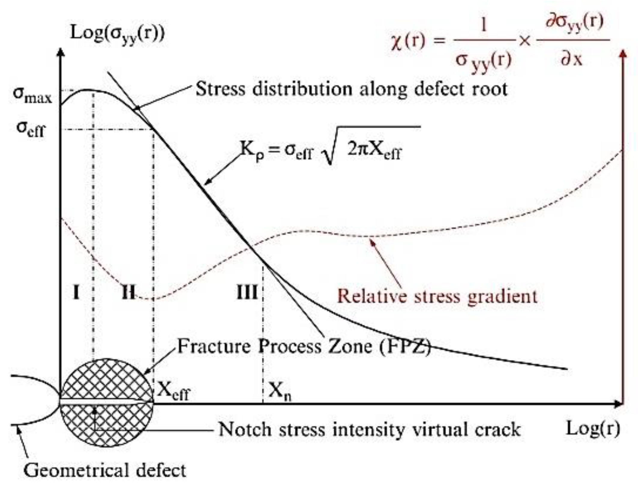
2.1. Volumetric Method

One of the simplest techniques for predicting structural integrity is the volumetric method. The implementation of this technique depends on the concept of the notch stress intensity factor, which is built on the idea that the failure mechanism necessitates a physical volume [31]. This idea is explained by the fact that the kind of loading, the geometry of the configuration, and the scale effect determine the failure stress. The maximum surface stress known by the hot spot stress value cannot describe the effect of these criteria on the fracture resistance. We must incorporate the stresses and stress gradient of all surrounding points on the volume of the failure mechanism. Similar to the shapes of plastic zones, the bulk is assumed quasi-cylindrical. The diameter of this cylinder is called «distance effective»; in this region, the tensile stress can be approximated. Therefore, the amount of this stress is built on two parameters: The effective stress σ e f f and effective distance   X e f f . The figure below explains the parameters of this technique. The bi-logarithmic distribution of elastic−plastic stresses along the ligament shows three different regions; the first region (I) shows the increase in stress σ y y up to a maximum value; then, in the second region (II), there is a decrease until the elastoplastic state occurs. Region (III) indicates the linear behaviour of the curve shown in Figure 1. The projection of the minimum amount of the relative stress gradient χ gives distance and effective stress. The relationship of the relative stress gradient is:
χ ( r )   = 1 σ y y ( r )   σ y y ( r ) r
where σ y y ( r ) indicates the crack opening stress and χ(r) indicates the relative stress gradient.
The mean quantity of the stress distribution through the effective distance represents the effective stress. Indeed, to improve the numerical result of this stress, as well as to incorporate the value of the stress gradient related to the load mode and the configuration, the stress is multiplied by a weight function:
σ e f f = 1 X e f f 0 X e f f σ y y ( r ) × φ ( r ) dr
where σ e f f represents the effective stress, X e f f represents the effective distance, and φ represents the weight function.
The calculation of these parameters using this approach gives us the stress intensity factor:
k   =   σ e f f   2 π . X e f f

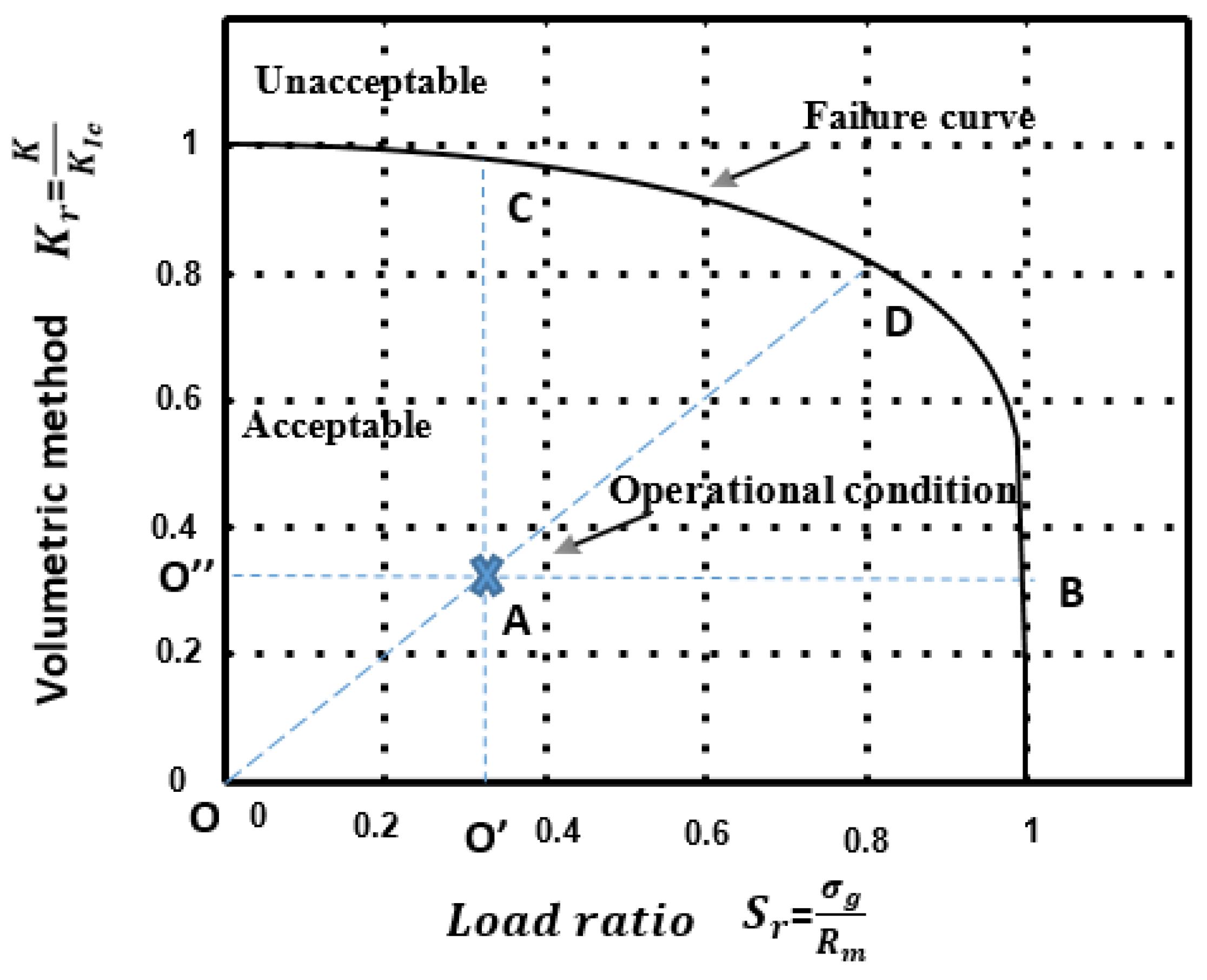
2.2. Determination of Failure Assessment Diagram

The fundamental fracture mechanics correlation collaborates three factors: The length of defect a, the constraint enforced σ a p p , and the fracture resistance R. R can represent the crucial stress intensity factor   K I c , the crucial value of the J integral J c , or the critical crack opening displacement δ c . In this survey, the utilisation of the FAD concept requires the replacement of these parameters by the calculation of two parameters, i.e., the load ratio S r (or equivalently   L r ) and the toughness ratio Kr. The failure curve is defined by:
ƒ ( S r ) = K r
where K r   is the non-dimensional critical crack driving force and S r (or equivalently   L r ) the non-dimensional load. Structures that are subjected to loads and present a surface defect are represented by a control point in the plane   K r , S r :
K r   =   k K I c ,   S r   =     σ a p p R m
where K and K I c are the stress intensity factor and fracture toughness, respectively, and σ a p p   and R m are the applied stress and ultimate strength, respectively.
The construction of this curve was taken from a plasticity correction introduced by Dugdale’s model [33]. This methodology considers that any sort of failure from a fragile crack to plastic collapse is obtained from the brittle fracture by a plasticity correction. Several methods are used to determine this curve: Structural INTegrity Assessment Procedure (SINTAP) in Europe [34], Electric Power Research Institute (EPRI) in the United States [35], and R6 in the UK [36]. The mathematical expression of this curve determined from the SINTAP method is presented by:
ƒ   ( S r )   =   [ 1 + S 2 r 2 ] 1 2 [ 0.3 + 0.7 e ( 0.6 S 6 r ) ]   for   0 S r 1
In the FAD procedure, the failure region was estimated by using a failure curve, the acceptable region, and the unacceptable region. A conventional FAD is represented [21] in Figure 2.
If the operational condition is situated as shown in Figure 2, we can ensure the safety of our design; if it is situated on the failure curve, failure will arise by crack propagation. From the assessment point A, we can specify the safety factors:
ƒ s , σ   =   O B O A ,   ƒ s , a   =   O D O A ,   ƒ s , K   =   O C O A
where, ƒ s , σ ,     ƒ s , a ,   ƒ s , K represent the safety factor on the load, on the size of the defect, and on the stress intensity factor, respectively.

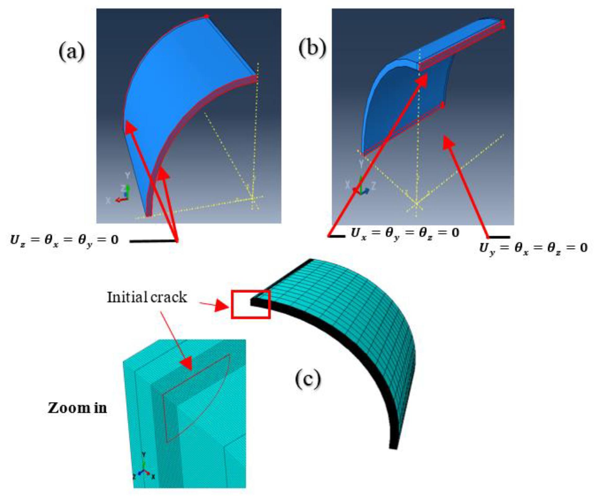
2.3. The Extended Finite Element Method

The XFEM-based method executed in the finite element system Abaqus/standard (v.2017) was employed in this survey. This method has appeared as an alternative to the classical finite element method. It is built on the principle of partition of unity (PU) [20], and has the ability to follow the crack without conforming to the mesh; thus, it is not required for this re-meshing operation. The existence of discontinuities in an element is available now with this approach. The idea is to enrich the degrees of freedom by adding a special function of displacement. According to the partition of unity, the nodes corresponding to the elements completely cut by the crack were enriched by the discontinuous shape function; thus, the elements including the crack front were enriched by singular shape functions. The approximation of a displacement field U with the XFEM discretisation is determined as follows:
U ( x )   =   I   =   1 N N I ( x ) [ u I + H ( x ) a I + β   =   1 4 F β ( x ) b β I ]
where N I   is the finite element shape function, and u I , a I ,   b β I represent the classical, discontinuous, and singular degrees of freedom, respectively. H(x) and F β ( x ) are the Heaviside enrichment function that returns the displacement jumps through the crack surface, and the asymptotic crack-tip function that captures the singularity near the crack tip field, respectively.
With the treatment of crack initiation and propagation using XFEM, Abaqus offers two types of damage modelling; linear elastic fracture mechanics (LEFM) and the cohesive segments approach. In this work, XFEM is combined with the cohesive approach. It is useful and shows great results in the literature [25,37,38]. The principle of the traction separation law constructs the cited procedure, and it is a very smart and powerful method to simulate initiation and growth for brittle or ductile fracture. The main parameters that constitute this model are the maximum principal stress σ max , p s   and fracture energy   G c . These damage parameters are used in Abaqus to control the crack.
In addition, of the cohesive method, numerical modelling of the contact between two bodies is a significant task in computational mechanics and has a vast implementation in engineering [39]. In this field, we selected a contact interaction property that specifies the compressive behaviour of the crack surface [40].

3. Material Properties

An isotropic elastoplastic material was chosen to simulate the structure of our study, where the choice of the properties of this material was taken from the experimental work of [3]. In the reference mentioned, the strain−stress is a result of a tensile test and it is represented as an engineering stress−strain. In Abaqus, like most FEA software, the appropriate stress−strain data must be entered as true stress and true strain. To obtain the stress−strain curve, we have utilised the Ramberg−Osgood law as mentioned in the experimental test of [3]:
ε   =   σ E + ( σ K ) 1 n
where K = 49,454 MPa, n = 0.068.
The material used in this study is P264GH, which is stainless steel and is known for its forming and welding characteristics. It is considered among the most established steels in the field of engineering, specifically in the piping domain. Table 1 describes the mechanical properties of this kind of material.
Figure 3 illustrates the dimension of the example model examined in this overview. The example represents a cylindrical shape of a shell made of steel P264GH. This geometry includes a longitudinal surface defect, and it was exposed to internal pressure during the numerical simulation.
The cylinder size was set to L = 625 mm, Ri = 193.2 mm, R0 = 203.2 mm, t = 10 mm and the defect size set to a/t = 0.2 mm, 2c/a = 4, ρ = 0.25 . The data of this geometry are imported from [41].

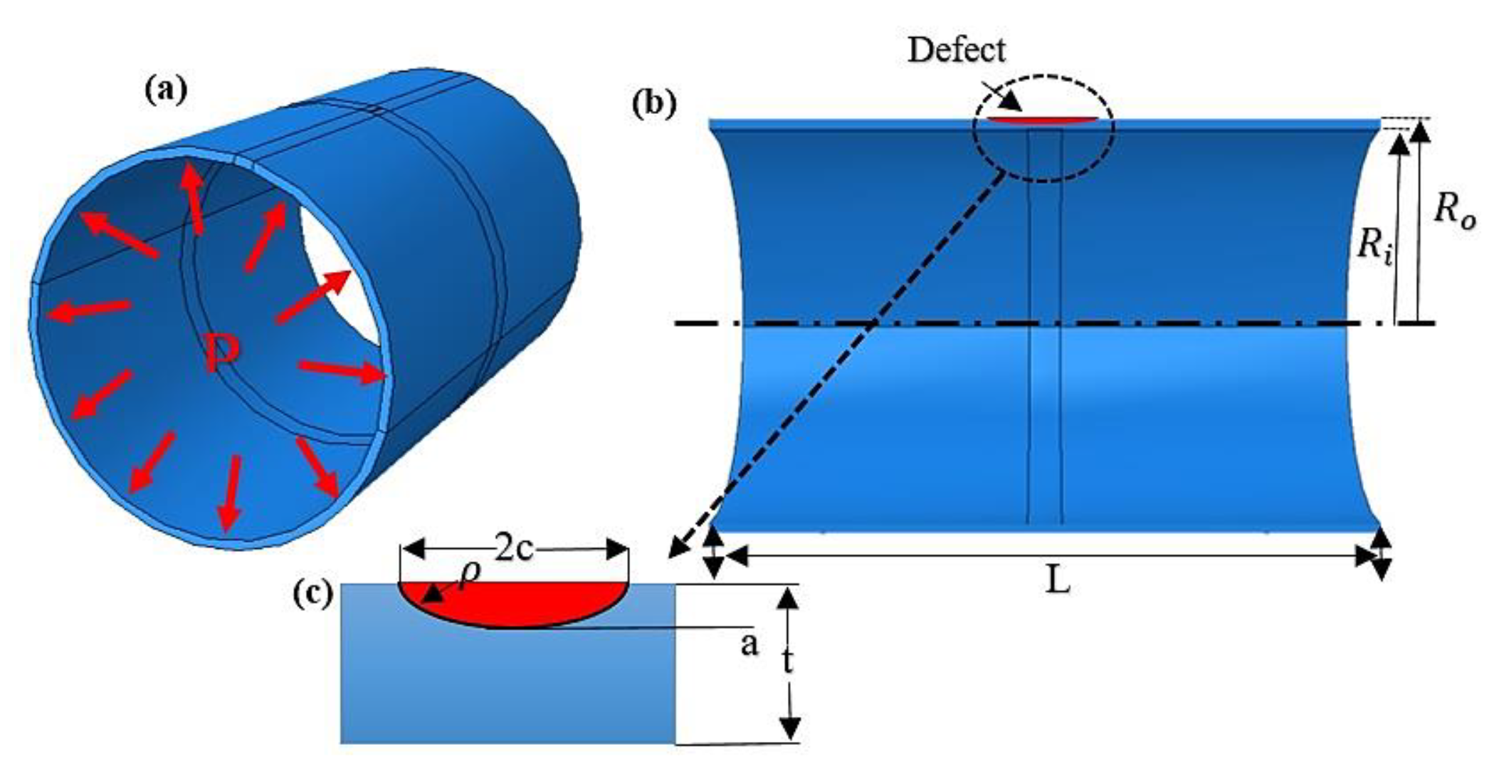
4. Numerical Procedure and Results

The FAD has most recently been utilised for pipeline integrity [42], evaluating a cracked pipe using the FAD construction built on the curve of stress−strain. In addition, in [41], they modelled a pipe with an external defect to build the FAD, and the modelling was done by the CFEM using CASTEM software. We can also find similar research works that have been interested in cracked pipelines such as [7,8,9], where they have focused on cases where plastic deformation is important. They have been interested in circumferential cracks, and the classical finite element model is used to study the CTOD failure parameter. Thus, the FAD and XFEM were used to evaluate the liquefied petroleum gas cylinder (API 579) [25]. In this study, we have combined the volumetric technique (VM) based on the XFEM and FAD for studying the pipe steel P264GH. In order to determine the parameters of the VM, we have to calculate the elastoplastic circumferential stress distribution around the defect σ y y . The geometry of our study was numerically modelled with XFEM in a three-dimensional space of the solid type established with ABAQUS/CAE with the standard/explicit scheme, for the purpose of establishing the curve σ y y of a steel pipe exposed to inner pressure. The cylinder configuration was simulated as a 3D deformable solid structure, and to reduce the calculation time, we have turned our problem into a symmetry problem, which is why, in the transversal and axis direction, we applied symmetric boundary conditions, so just a quarter model could be simulated. The XFEM model design with enforced limit conditions is introduced in Figure 4. where symmetric boundary conditions on the transversal and axial direction are illustrated in Figure 4. The mesh is shown in Figure 4. with 338,148 nodes and 322,000 elements.
In the XFEM approach, the geometry is independently meshed using an eight-node linear brick element with reduced integration and hourglass control (C3D8R) in the Abaqus element library. The crack initial is semi-elliptical, and it is axial because, in the axial direction, the defect becomes critical. Regarding the loads, we applied a pressure of 60 bar for studying the elastoplastic behaviour because the plastic comportment appears when the pressure exceeds 40 bar; this choice is based on the experimental study of [43]. To make a good calculation, the dimensions of the elements through the thickness of the wall (i.e., the path of propagation) is 0.1 mm, although the rest of the structure was meshed with coarser elements. For this study, crack propagation modelling is carried out by combining the XFEM method and cohesive segments approach [44], where this technique has been most recently employed [45,46]. This method was based on the traction separation law. The use of this methodology lets us avoid the singular shape function, and just the Heaviside function was considered [47]. The failure mechanism includes two parameters: The damage initiation and damage evolution criterion. The structural behaviour is assumed linear-elastic up to the initiation criterion being reached, and this parameter is based on stress or strain, where both are available in Abaqus software. Then, material degradation depends on the damage evolution, where two kinds of parameters define the evolution of damage: The first parameter consists of specifying the effective displacement at total failure, and the second involves specifying the energy dissipated because of the failure.
In this study, mode I is the mode of rupture under consideration; it is the opening of the crack where the tensile stress will be normal to the crack plane. With a view to study the rupture mechanism, we have considered the maximum principal stress (MAXPS) and fracture energy as the two critical factors of failure that check crack initiation and toughness. The ultimate tensile strength was employed for the max principal stress σ max p s   =   σ u l t , and the damage energy was estimated by G   =   K 2 I C E [48]. Due to the importance of the contact in the engineering field, and especially in cracking problems, we selected a contact property using the penalty method for improving the result of this simulation.

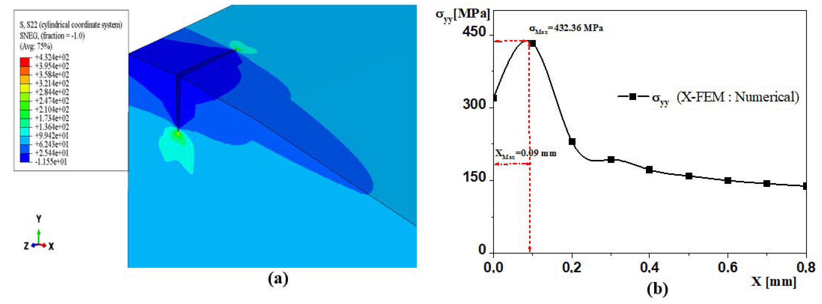
4.1. Computational ElastoPlastic Stress Distribution around the Defect

In this study, we considered the defect as a crack because it behaves like a notch, and the radius of curvature is too small. For that reason, we utilised the volumetric method. The distribution of the elastoplastic circumferential stress ahead of the defect is illustrated in Figure 5. The curve has a maximal value of σ max   =   43 , 236   MPa at Xmax = 0.09 mm. The results are close to the work of [41], who carried out the simulation by the finite element method under CASTEM Software, obtaining σ max = 435.49   MPa at X max = 0.087   mm .
The equation below presents the polynomial fit of the opening stress distribution:
σ y y ( x )   =   i = 0 n a i x i
The polynomial fit approximation distribution of σ y y and the gradient of this distribution are given in Figure 6. Moreover, we used relation (1) to compute the distribution of the relative stress gradient χ ahead the defect. From Figure 6, we can extract the effective value X e f f   =   0.17   mm , which correlates to the minimum of the relative stress gradient χ. Using equation (2) will allow us to determine the effective stress σ e f f   =   311   MPa . The volumetric technique enables the estimation of the stress intensity factor as follows:
K   =   311 2 π × 0.17   =   10.164   MPa m

4.2. FAD Curve Based on the Volumetric Method

To empower the reliability assessment of the steel pipe with a semi-elliptical defect in the designing, the FAD curve based on the stress intensity factor has been plotted in this paper. The expression used to construct the FAD curve is described in Equation (6) above. We refer to Table 2 in order to find out the coordinates of the operational condition.
Then, the FAD curve is represented in Figure 7. From the diagram, the operational condition or the assessment point of coordinates ( S r ,   L r ) is located in the safety zone, as described in the theoretical part, which means that the structure with a defect of a / t = 0.2 ,   2 c / t = 4 subjected to a pressure of 60 bar is safe, and no failure occurs. Moreover, the safety ratio related to the design circumstance is determined by the following rapport:
f s   =   O D O A
An acceptable configuration is generally examined by comparing the calculated safety ratio with the usual value ( f s   =   2 ) [26]. In our case, we obtained a value of f s   = 4.23 > f s   =   2 .

5. Discussion

The results indicate that the evaluation of the integrity of a cracked structure can be done by the combination of the XFEM method and the volumetric method. The data obtained from these two methods contributed to the construction of the FAD diagram. As the sensitivity of the stress distribution along the defect requires the use of the XFEM method to eliminate all types of errors due to the use of other techniques mentioned above, the stability of a cracked structure can be examined using the famous FAD diagram.
By comparing these results to those presented in [41], and as we have taken the same dimensions of defects, we found that the curve of the stress distribution corresponding to the model CFEM method and the curve of the stress distribution corresponding to the model XFEM method are almost identical. They have a relative error of 0.72%. We chose the XFEM model to improve the quality of the computation results and to precisely eliminate the singularity effect at the crack point.
The fracture parameter used in this research project is the stress intensity factor; the difference between this research and other researches is in the method of extraction of this parameter. That is why we have combined the XFEM method and the volumetric method. It should be noted that the method used (volumetric method) to extract the stress intensity factor is generally exploited for notch processing. However, we have assumed that the crack behaves as a notch. We have obtained 10.164 MPa m . Among the reasons for applying this idea is that the study of crack propagation in Abacus software does not allow us to directly extract this parameter, except that the crack remains stable, and this is not the case here. The FIC is one of the parameters used to construct the famous FAD diagram. Normally, the point (0.0, 1.0) limits this diagram on the Y-axis and (1.0, 0.0) on the X-axis. Figure 7 shows an offset on the X-axis, but it does not influence the quality of the results. It may be due to the effect of plasticity at the crack tip, but this is not the aim of this research; we will study this effect in future work. Finally, the stability of the cracked structure depends on the value of the safety factor, which is 4.23. This value shows that the structure can function correctly with this type of defect and this type of loading.
Therefore, it can be concluded that the strategy provided in this paper has been successfully validated on cracked pipelines. The results obtained by the use of FAD based on XFEM permit the dealing of localised cracks in welds in future works, as well as the possibility to replace the stress intensity factor by nonlinear mechanical parameters including the integral J or crack-type opening displacement CTOD. The effect of plasticity is not studied in this paper, although the results obtained encourage us to go further to treat the effect of plasticity at the crack tip as the XFEM method has not yet justified an accuracy in this field. It is necessary to develop a user subroutine to define an element code to integrate it with XFEM.

6. Conclusions

This survey provides the results of a detailed numerical study executed on a P264GH steel pipe with an axial defect under the impact of internal pressure. The main purpose was to validate the use of the XFEM method, which is more robust when compared to CFEM. The numerical results are exploited to obtain the stress intensity factor using the volumetric method. This method is mainly used to deal with the notch problem. By using a crack in this research, we verify the hypothesis that the crack can behave like a notch when loaded. The results from this research are verified against the classical FEM, which proves the consistency. Further, the obtained results enable us to build the FAD diagram, which allows us to evaluate the safety of a structure. To conclude, the XFEM method is indicated as a viable solution to replace the CFEM method due to its efficiency and simplicity. Thus, in the mechanical side, the FAD diagram can be a good indication of the influence of a defect on a design, as well as the stability of the geometry.

Author Contributions

Conceptualization, S.M.; Data curation, S.M. and D.K.R.; Formal analysis, K.Y.; Project administration, H.M. and A.E.; Resources, A.E.; Writing—original draft, C.I.P.; Writing—review and editing, C.I.P. All authors have read and agreed to the published version of the manuscript.

Funding

This research received no external funding.

Conflicts of Interest

The authors declare no conflict of interest.

References

  1. Capelle, J.; Gilgert, J.; Dmytrakh, I.; Pluvinage, G. The effect of hydrogen concentration on fracture of pipeline steels in presence of a notch. Eng. Fract. Mech. 2011, 78, 364–373. [Google Scholar] [CrossRef]
  2. Lam, C.; Zhou, W. Statistical analyses of incidents on onshore gas transmission pipelines based on PHMSA database. Int. J. Press. Vessel. Pip. 2016, 145, 29–40. [Google Scholar] [CrossRef]
  3. Moustabchir, H.; Arbaoui, J.; Azari, Z.; Hariri, S.; Pruncu, C.I. Experimental/numerical investigation of mechanical behaviour of internally pressurized cylindrical shells with external longitudinal and circumferential semi-elliptical defects. Alex. Eng. J. 2018, 57, 1339–1347. [Google Scholar] [CrossRef]
  4. Pachoud, A.J.; Manso, P.A.; Schleiss, A.J. Stress intensity factors for axial semi-elliptical surface cracks and embedded elliptical cracks at longitudinal butt welded joints of steel-lined pressure tunnels and shafts considering weld shape. Eng. Fract. Mech. 2017, 179, 93–119. [Google Scholar] [CrossRef]
  5. Zhang, Y.; Xiao, Z.; Luo, J. Fatigue crack growth investigation on offshore pipelines with three-dimensional interacting cracks. Geosci. Front. 2018, 9, 1689–1697. [Google Scholar] [CrossRef]
  6. Benhamena, A.; Aminallah, L.; Bouiadjra, B.B.; Benguediab, M.; Amrouche, A.; Benseddiq, N. J integral solution for semi-elliptical surface crack in high density poly-ethylene pipe under bending. Mater. Des. 2011, 32, 2561–2569. [Google Scholar] [CrossRef]
  7. Dake, Y.; Sridhar, I.; Zhongmin, X.; Kumar, S.B. Fracture capacity of girth welded pipelines with 3D surface cracks subjected to biaxial loading conditions. Int. J. Press. Vessel. Pip. 2012, 92, 115–126. [Google Scholar] [CrossRef]
  8. Zhang, Y.; Xiao, Z.; Zhang, W. On 3-D crack problems in offshore pipeline with large plastic deformation. Theor. Appl. Fract. Mech. 2013, 67, 22–28. [Google Scholar] [CrossRef]
  9. Zhang, Y.; Yi, D.; Xiao, Z.; Huang, Z. Engineering critical assessment for offshore pipelines with 3-D elliptical embedded cracks. Eng. Fail. Anal. 2015, 51, 37–54. [Google Scholar] [CrossRef]
  10. Paarmann, M.; Sander, M. Analytical determination of stress intensity factors in thick walled thermally loaded components. Eng. Fract. Mech. 2020, 235, 107125. [Google Scholar] [CrossRef]
  11. Agbo, S.; Lin, M.; Ameli, I.; Lmanpour, A.; Duan, D.-M.; Roger Cheng, J.J.; Adeeb, S. Experimental evaluation of the effect of the internal pressure and flaw size on the tensile strain capacity of welded X42 vintage pipelines. Int. J. Press. Vessel. Pip. 2019, 173, 55–67. [Google Scholar] [CrossRef]
  12. Shibanuma, K.; Hosoe, T.; Yamaguchi, H.; Tsukamoto, M.; Suzuki, K.; Aihara, S. Crack tip opening angle during unstable ductile crack propagation of a high-pressure gas pipeline. Eng. Fract. Mech. 2018, 204, 434–453. [Google Scholar] [CrossRef]
  13. Anderson, T.L. Fracture Mechanics: Fundamentals and Applications; CRC Press: Boca Raton, FL, USA, 2017. [Google Scholar]
  14. Barsoum, R.S. On the use of isoparametric finite elements in linear fracture mechanics. Int. J. Numer. Methods Eng. 1976, 10, 25–37. [Google Scholar] [CrossRef]
  15. Belytschko, T.; Lu, Y.Y.; Gu, L. Element-free galerkin methods. Int. J. Numer. Methods Eng. 1994, 37, 229–256. [Google Scholar] [CrossRef]
  16. Partridge, P.W.; Brebbia, C.A.; Wrobel. (Eds.) Dual Reciprocity Boundary Element Method; Springer Science & Business Media Publishing: Berlin/Heidelberg, Germany, 2012. [Google Scholar]
  17. Moës, N.; Dolbow, J.; Belytschko, T. A finite element method for crack growth without remeshing. Int. J. Numer. Methods Eng. 1999, 46, 131–150. [Google Scholar] [CrossRef]
  18. Bazazzadeh, S.; Mossaiby, F.; Shojaei, A. An adaptive thermo-mechanical peridynamic model for fracture analysis in ceramics. Eng. Fract. Mech. 2020, 223, 106708. [Google Scholar] [CrossRef]
  19. Molnár, G.; Gravouil, A. 2D and 3D abaqus implementation of a robust staggered phase-field solution for modeling brittle fracture. Finite Elem. Anal. Des. 2017, 130, 27–38. [Google Scholar] [CrossRef] [Green Version]
  20. Melenk, J.; Babuska, I. The partition of unity finite element method: Basic theory and applications. Comput. Methods Appl. Mech. Eng. 1996, 139, 289–314. [Google Scholar] [CrossRef] [Green Version]
  21. Pluvinage, G.; Bouledroua, O.; Meliani, M.H.; Suleiman, R. Corrosion defect analysis using domain failure assessment diagram. Int. J. Press. Vessel. Pip. 2018, 165, 126–134. [Google Scholar] [CrossRef]
  22. Kirin, S.; Sedmak, A.; Zaidi, R.; Grbović, A.; Šarkočević, Ž. Comparison of experimental, numerical and analytical risk assessment of oil drilling rig welded pipe based on fracture mechanics parameters. Eng. Failure Anal. 2020, 104600. [Google Scholar] [CrossRef]
  23. Bergant, M.A.; Yawny, A.A.; Perez Ipiña, J.E. Structural integrity assessments of steam generator tubes using the FAD methodology. Nucl. Eng. Des. 2015, 295, 457–467. [Google Scholar] [CrossRef]
  24. Bergant, M.A.; Yawny, A.A.; Ipiña, J.E.P. A comparison of failure assessment diagram options for inconel 690 and incoloy 800 nuclear steam generators tubes. Ann. Nucl. Energy 2020, 140, 107310. [Google Scholar] [CrossRef]
  25. Kingklang, S.; Daodon, W.; Uthaisangsuk, V. Failure investigation of liquefied petroleum gas cylinder using FAD and XFEM. Int. J. Press. Vessel. Pip. 2019, 171, 69–78. [Google Scholar] [CrossRef]
  26. Pluvinage, G.; Capelle, J.; Schmitt, C. Methods for assessing defects leading to gas pipe failure. Handb. Mater. Fail. Anal. Case Stud. Oil Gas Ind. 2016, 55–89. [Google Scholar] [CrossRef]
  27. Pluvinage, G. Pipe-defect assessment based on the limit analysis, failure-assessment diagram, and subcritical crack growth. Mater. Sci. 2006, 42, 127–139. [Google Scholar] [CrossRef]
  28. Pluvinage, G.J.; Capelle, J.; Meliani, M.H. Pipe networks transporting hydrogen pure or blended with natural gas, design and maintenance. Eng. Fail. Anal. 2019, 106, 104164. [Google Scholar] [CrossRef]
  29. Lazzarin, P.; Berto, F.; Zappalorto, M. Rapid calculations of notch stress intensity factors based on averaged strain energy density from coarse meshes: Theoretical bases and applications. Int. J. Fatigue 2010, 32, 1559–1567. [Google Scholar] [CrossRef]
  30. Adib, H.; Jallouf, S.; Schmitt, C.; Carmasol, A.; Pluvinage, G. Evaluation of the effect of corrosion defects on the structural integrity of X52 gas pipelines using the SINTAP procedure and notch theory. Int. J. Press. Vessel. Pip. 2007, 84, 123–131. [Google Scholar] [CrossRef]
  31. Pluvinage, G. Fracture and Fatigue Emanating from Stress Concentrators; Springer Science & Business Media Publishing: Berlin/Heidelberg, Germany, 2007. [Google Scholar]
  32. Bolzon, G.; Boukharouba, T.; Gabetta, G.; Elboujdaini, M.; Mellas, M. Integrity of Pipelines Transporting Hydrocarbons: Corrosion, Mechanisms, Control, and Management; Springer Science & Business Media Publishing: Berlin/Heidelberg, Germany, 2011. [Google Scholar]
  33. Milne, I.; Ainsworth, R.; Dowling, A.; Stewart, A. Assessment of the integrity of structures containing defects. Int. J. Press. Vessel. Pip. 1988, 32, 3–104. [Google Scholar] [CrossRef]
  34. Webster, S.; Bannister, A. Structural integrity assessment procedure for Europe–of the SINTAP programme overview. Eng. Fract. Mech. 2000, 67, 481–514. [Google Scholar] [CrossRef]
  35. Ainsworth, R.; Hooton, D.; Green, D. Failure assessment diagrams for high temperature defect assessment. Eng. Fract. Mech. 1999, 62, 95–109. [Google Scholar] [CrossRef]
  36. Lin, Y.; Xie, Y.; Wang, X. Probabilistic fracture failure analysis of nuclear piping containing defects using R6 method. Nucl. Eng. Des. 2004, 229, 237–246. [Google Scholar] [CrossRef]
  37. Ameli, I.; Asgarian, B.; Lin, M.; Agbo, S.; Cheng, R.; Duan, D.-M.; Adeeb, S. Estimation of the CTOD-crack growth curves in SENT specimens using the eXtended finite element method. Int. J. Press. Vessel. Pip. 2019, 169, 16–25. [Google Scholar] [CrossRef]
  38. Higuchi, R.; Okabe, T.; Nagashima, T. Numerical simulation of progressive damage and failure in composite laminates using XFEM/CZM coupled approach. Compos. Part A: Appl. Sci. Manuf. 2017, 95, 197–207. [Google Scholar] [CrossRef]
  39. Khoei, A.R. Extended Finite Element Method: Theory and Applications; John Wiley & Sons: Hoboken, NJ, USA, 2014. [Google Scholar]
  40. Specifying a Contact Interaction Property for XFEM. Available online: https://abaqus docs.mit.edu/2017/English/SIMACAECAERefMap/simacae-t-enghelpxfemcontact.htm (accessed on 21 May 2020).
  41. Moustabchir, H.; Pruncu, C.I.; Azari, Z.; Hariri, S.; Dmytrakh, I. Fracture mechanics defect assessment diagram on pipe from steel P264GH with a notch. Int. J. Mech. Mater. Des. 2016, 12, 273–284. [Google Scholar] [CrossRef]
  42. Wang, X.; Shuai, J.; Lv, Z. Study on FAD curves of steel pipes based on stress-strain curves. Theor. Appl. Fract. Mech. 2020, 102451. [Google Scholar] [CrossRef]
  43. Moustabchir, H.; Azari, Z.; Hariri, S.; Dmytrakh, I. Experimental and numerical study of stress-strain state of pressurised cylindrical shells with external defects. Eng. Fail. Anal. 2010, 17, 506–514. [Google Scholar] [CrossRef]
  44. Abaqus Documentation. Available online: https://abaqus docs.mit.edu/2017/English/SIMACAEEXCRefMap/simaexc-c-docproc.htm (accessed on 17 May 2020).
  45. Lin, M.; Agbo, S.; Duan, D.-M.; Cheng, J.R.; Adeeb, S. Simulation of crack propagation in API 5L X52 pressurized pipes using XFEM-based cohesive segment approach. J. Pipeline Syst. Eng. Pract. 2020, 11, 04020009. [Google Scholar] [CrossRef]
  46. Okodi, A.; Lin, M.; Yoosef-Ghodsi, N.; Kainat, M.; Hassanien, S.; Adeeb, S. Crack propagation and burst pressure of longitudinally cracked pipelines using extended finite element method. Int. J. Press. Vessel. Pip. 2020, 104115. [Google Scholar] [CrossRef]
  47. Du, Z. EXtended Finite Element Method (XFEM) in Abaqus; Simulia: Johnston, RI, USA, 2009. [Google Scholar]
  48. Reinhardt, L.; Cordes, J.; Geissler, D. Using Co-simulation to Extend the Usage of XFEM; Simulia: Johnston, RI, USA, 2011. [Google Scholar]
Figure 1. The distribution of elastic−plastic stress along defect [32].
Applsci 10 06129 g001
Figure 2. Assessment diagram failure.
Applsci 10 06129 g002
Figure 3. Schematic of dimension model: (a) Pipe 3D model, (b) dimensions of geometry model with defect, (c) characteristics of defect.
Applsci 10 06129 g003
Figure 4. Finite element model and boundary conditions: (a,b) Symmetric boundary in the X, Y, and Z direction, and (c) mesh of the quart model using extended finite element method (XFEM).
Applsci 10 06129 g004
Figure 5. The distribution of the elastoplastic circumferential stress ahead of the defect: (a) Result of the simulation by the XFEM technique; (b) the curve of σyy.
Applsci 10 06129 g005
Figure 6. Schematic of polynomial fit and gradient of σyy.
Applsci 10 06129 g006
Figure 7. Failure assessment diagram to establish the operational condition.
Applsci 10 06129 g007
Table 1. Mechanical properties of steel P264GH.
Young’s ModulusE = 207 GPa
Poisson’s ratio ϑ = 0.3
Yield stressRe = 340 MPa
Ultimate tensile strengthRm = 440 MPa
Elongation to fractureA = 35%
Table 2. Coordinates of the operational condition.
σ e f f X e f f K = σ e f f 2 π X e f f σ a p p = P D 2 t R m K r   = K K I c S r = σ a p p R m
3110.1710.161115.924400.1060.263

