Block-Based Steganography Method Using Optimal Selection to Reach High Efficiency and Capacity for Palette Images


Department of Computer Science, National Chiao Tung University, Hsinchu 300, Taiwan
*
Author to whom correspondence should be addressed.
Appl. Sci. 2020, 10(21), 7820; https://0-doi-org.brum.beds.ac.uk/10.3390/app10217820
Submission received: 11 October 2020
/
Revised: 1 November 2020
/
Accepted: 2 November 2020
/
Published: 4 November 2020
(This article belongs to the Special Issue Data Hiding and Its Applications: Digital Watermarking and Steganography)
Abstract
:The primary goal of steganographic methods is to develop statically undetectable methods with high steganographic capacity. The embedding efficiency is one kind of measure for undetectability. Block-based steganography methods have been proposed for achieving higher embedding efficiency under limited embedding capacity. However, in these methods, some blocks with larger embedding distortions are skipped, and a location map is usually incorporated into these methods to record the embedding status of each block. This reduces the embedding capacity for secret messages. In this study, we proposed a block-based steganography method without a location map for palette images. In this method, multiple secret bits can be embedded in a block by modifying at most one pixel with minimal embedding distortion; this enables each block to be used for data embedding; thus, our method provides higher embedding capacity. Furthermore, under the same capacity, the estimated and experimental embedding efficiencies of the proposed method are compared with those of Imaizumi et al. and Aryal et al.’s methods; the comparisons indicate that the proposed method has higher embedding efficiency than Imaizumi et al. and Aryal et al.’s methods.
1. Introduction
Steganography is a technique for secret communication, in which secret messages are embedded into common digital media such as images, audios, and videos. The original media is called “cover,” and the embedded media is called “stego.” Of these media, images are the most popular because they are widely transmitted over the Internet. Many image-based steganography methods [1,2,3,4,5,6,7,8,9,10,11,12,13,14,15,16,17] have been proposed and applied in raw [1,2,3,4,5], JPEG [6], VQ [7], and absolute moment block truncation coding (AMBTC) [8] images. However, the application in palette images [9,10,11,12,13,14,15,16,17] is limited. Palette images [18] have gained popularity. Graphics interchange format (GIF) is a type of palette image frequently used by young consumers to communicate and express themselves. GIF animations are widely used on social media platforms such as Tumblr, Twitter, Facebook, and Line [18,19].
A palette image includes a palette and an index table. The palette consists of a few (generally no more than 256) colors. Each pixel is represented by a color in the palette, and the index table records each pixel’s corresponding color index. In general, the order of colors in the palette is random. Because only limited colors are used in palette images, modifying a pixel’s color index considerably distorts the pixel color. Thus, embedding data into a palette image is more challenging than in other image formats.
Embedding methods are of two types. In pixel-based methods (PBMs) [9,10,11,12,13,14], a pixel is used as a unit to embed secret data. In block-based methods (BBMs) [15,16,17], a block is used as a unit to embed secret data.
Fridrich [11] proposed a method in which the colors of a palette are partitioned into two sets with different parities ( mod 2) to represent one secret bit. The capacity of this method is 1 bit per pixel (bpp). Under the same embedding capacity, Fridrich and Du [12] proposed an optimal parity assignment algorithm to improve image quality. Tzeng et al. [13] proposed an adaptive data-hiding scheme for palette images based on local complexity. An embedding capacity of approximately 0.1 bpp is used for most images [20]. Tanaka et al. [14] proposed an algorithm to partition colors into sets. Each set represents one type of -bit secret data. For each pixel, according to the secret data, the closest color in the corresponding set is determined to replace the pixel’s color. The embedding capacity is increased to bpp.
In [9,10,11,12,14], each pixel was used to embed secret data in PBMs. Therefore, the embedding distortion for a pixel may be large. In [13], an adaptive scheme was provided to skip pixels with large distortions. However, this reduced the capacity.
Imaizumi and Ozawa [15] proposed a BBM to embed bits into each block. In this method, first, all colors in a palette are reordered according to the color Euclidean distance. Next, for each block, the sum of all color indices is calculated and divided by to obtain a remainder. Then, some pixels in the block are selected, and their color indices are adjusted to obtain a remainder equal to the value of embedding secret data bits with the least embedding distortion. The embedding capacity is bpp. Imaizumi and Ozawa [16] adopted a block size of to improve the embedding capacity of their previous method [15]. Subsequently, Aryal et al. [17] used a block size of to improve the embedding capacity of the aforementioned method [16] and used the L*a*b color space to replace the RGB color space to improve image quality. In all of these BBMs [15,16,17], the palette of an image is first reordered. Then, for each block, under the consideration of minimum embedding distortion, several pixels are selected, and their color indices are modified by or . In the reordered palette, two colors with adjacent color indices may not be similar; some selected pixels may have large embedding distortion, which degrades image quality after data embedding. Furthermore, the color indices of some selected pixels may overflow or underflow after data embedding. To avoid using these blocks, an additional location map is required to record if a block is used to embed secret data. This reduces the embedding capacity for secret data because some blocks are skipped and some are used to embed the location map.
To address the aforementioned problem, a novel BBM for palette images was proposed in this study. First, Tanaka et al.’s -bit parity assignment [14] was used to assign a -bit parity to each color in the palette of an image. Then, for each block, at most one pixel was modified for data embedding, and no location map was required for data extraction. The proposed method provided higher capacity.
Note that the primary goal of steganographic methods [21] is to develop statically undetectable methods with high steganographic capacity. Steganographic capacity [21] is defined as the maximum number of bits that can be hidden in a given cover work, such that the probability of detection by an adversary is negligible. The embedding efficiency [21] is one kind of measure for undetectability, and it is defined as the number of embedded random message bits per embedding change. Crandall [22] mentioned that the most obvious method to reduce the possibility of detecting hidden information is to reduce the change density in the cover image. Since decreasing the change density raises the embedding efficiency, higher embedding efficiency will lower the detectability. Since BBMs reduce the change density, the detectability of these methods is lower.
2. Related Works
In this section, the parity assignment method proposed by Tanaka et al. [14] and referenced in the proposed method is first described. Then, the method proposed by Aryal et al. [17] is described; it is used to make a comparison with the proposed method.
2.1. Parity Assignment Method Proposed by Tanaka et al.
Tanaka et al. proposed an algorithm to assign parity bits to each color in the palette of an image. The algorithm contains two parts. In the first part, from the palette, closest colors () are determined sequentially, is assigned a -bit parity with value . Next, sets () are established, that is, . In the second part, from the unassigned colors, the color with the minimal distance from the last assigned color is determined. Next, the minimal distance of from each set is evaluated. Then, the maximal distance among {} is determined and is assigned as the parity of color . The procedure is repeated until all colors are assigned.
In the algorithm, the distance between two colors and is defined using the following expression:
The details of the parity assignment are described as follows:
- Step 1:
- Let be the set of all colors in the palette. Let , and assign parity to ; .
- Step 2:
- Let . Find an initial color using the following expression:; .
- Step 3:
- Let . Find color in with the minimum distance from using the following equation:; .
- Step 4:
- Repeat Step 3 until .
- Step 5:
- Let . Find color in with the minimum distance from using Equation (3).
- Step 6:
- In each , , find the color in with the minimum distance from using the following expression:
- Step 7:
- Find the maximum distance among all using the following expression:, .
- Step 8:
- Repeat Steps 5 to 7 until is empty.
2.2. Aryal et al.’s Method
Aryal et al.’s method [17] improves the capacity and image quality of Imaizumi et al.’s method [16]. In the method, the color of each pixel in the RGB color space is first converted to color (L*, a*, b*) in the L*a*b color space, and the CIEDE2000 formula [25] is used to calculate the color distance. The method includes three processes: Palette reordering, block embedding, and extraction. In the method, the -bit messages are embedded into each pixel matrix. For convenience, we assumed in the following processes.
2.2.1. Palette Reordering Process
- Step 1:
- Let the original palette be {}, the new palette be {}, and .
- Step 2:
- Set . Find the first color in using the following expression:where is the luminance component of color in the L*a*b color space.
- Step 3:
- Let , . Find color in with the minimum distance from using the following expression:where is the CIEDE2000 color distance [25] between and .
- Step 4:
- Repeat Step 3 until .
2.2.2. Embedding Process
- Step 1:
- Divide the cover image into nonoverlapping blocks, each of which contains pixels.
- Step 2:
- Reorder palette to obtain a new palette using the palette reordering process.
- Step 3:
- Consider a block with three pixels () and three secret data bits .
- Step 4:
- Let be the color index of in , .
- Step 5:
- Calculate and using the following equations.
- Step 6:
- Obtain and based on Table 1 and secret data .
- Step 7:
- If and , then go to Step 10.
- Step 8:
- If , then is changed by or ; this depends on whether or is smaller.
- Step 9:
- If , then three cases are possible:
- Case 1:
- If , then and are changed by or this depends on whether or is smaller.
- Case 2:
- If or , then either or is changed by ; this depends on whether or is smaller.
- Case 3:
- If or , then either or is changed by this depends on whether or is smaller.
- Step 10:
- Go to Step 3 until all secret data are embedded.
If any in the embedding process, the current block is skipped, and no secret data are embedded. An additional location map is required for recording if a block is used to embed secret data.
2.2.3. Extraction Process
- Step 1:
- Divide the stego image into nonoverlapping blocks, each of which contains pixels.
- Step 2:
- Reorder palette to obtain a new palette through the palette reordering process used in the embedding process.
- Step 3:
- According to the location map, consider an embedded block with three pixels (). Let be the color index of in , .
- Step 4:
- Calculate and using the following equations:
- Step 5:
- Extract according to Table 1, and .
- Step 6:
- Go to Step 3 until all embedded blocks are processed.
In Imaizumi et al. and Aryal et al.’s methods, for data extraction, the receiver requires the positions of embedded blocks. Thus, a location map with one bit for each block should be transmitted to the receiver; this will reduce the embedding capacity for secret data, and will be discussed in Section 4. To overcome this disadvantage, a novel BBM was proposed; it does not require a location map.
3. Proposed Method
To avoid using a location map and to obtain higher embedding efficiency and capacity, a novel BBM for palette images is proposed. The method includes three processes: Parity assignment, embedding, and extraction. In the parity assignment process, Tanaka et al.’s assignment [14] is used to assign a -bit parity to each color in a palette. Through the assignment, a stego image with lower embedding distortion can be obtained, such that a location map is not required for secret data extraction. In the embedding process, an optimal scheme is provided to select the pixel in a block with the minimal embedding distortion; this makes each block used for data embedding. The embedding process is performed as follows:
3.1. Embedding Process
- Step 1:
- Divide the cover image into nonoverlapping blocks, each of which contains pixels.
- Step 2:
- Use Tanaka et al.’s parity assignment to assign a -bit parity to each color in palette .
- Step 3:
- Take one block with pixels () and secret data bits sequentially.
- Step 4:
- Let be the color of , and be the parity of , .
- Step 5:
- Calculate using the following expression:
- Step 6:
- If , then go to Step 10.
- Step 7:
- For each pixel , parity is calculated using the following equation:
- Step 8:
- For each pixel , find a new color with parity according to the following equation:where is the set of all colors with parity .
- Step 9:
- Consider pixel satisfying the following expression, and set the color of to be .
- Step 10:
- Repeat Steps 3 to 9 until all blocks are processed.
In Step 2, Tanaka et al.’s parity assignment is used; it makes each color be able to find a closer color in each set with a different parity. In Step 8, for each pixel, we always select the color with the required parity and the minimal embedding distortion to replace the original color. In Step 9, at most one pixel is modified with the minimal embedding distortion. Through these three steps, each block is used to embed secret data, and the embedding quality is also improved.
3.2. Extraction Process
In the extraction process, the receiver uses the same parity assignment as that used in the embedding process to assign a -bit parity to each color. The extraction process is as follows:
- Step 1:
- Divide the stego image into nonoverlapping blocks, each of which contains pixels.
- Step 2:
- Use Tanaka et al.’s parity assignment to assign a -bit parity to each color in palette .
- Step 3:
- Take a block with pixels () sequentially.
- Step 4:
- Use Equation (12) to obtain .
- Step 5:
- Set to be the secret data bits .
- Step 6:
- Repeat Steps 3 to 5 until all blocks are processed.
Because each block is used to embed secret data, the receiver does not require a location map in data extraction.
4. The Analysis for Embedding Capacities
As mentioned previously, both Imaizumi et al. [16] and Aryal et al.’s [17] methods need a location map in the extraction process; thus, the location map should be transmitted through another channel or be embedded in the stego image. However, it is unreasonable to transmit the location map through another channel. Thus, in the following, we only consider the location map embedded in the stego image. Let an image size be , block size be , the embedding bits for each block be , then the total block number . Assume that in the location map, each block is represented by one bit, 1 stand for the corresponding block used for embedding; 0 for skipping. Let be the size of the location map, assume that the location map is embedded in the first blocks, then the number of available blocks for secret data embedding is . Thus, should satisfy the following equation:
Note that the embedding capacity (bits) is . Let an image size be and block size be , then . Let ; through Equation (16), we can obtain , that is, the number of available blocks for secret data embedding is 12288, and the block number needed for recording the location map is 4096. Table 2 shows embedding capacities for Imaizumi et al.’s, Aryal et al.’s, and the proposed methods. In the table, we can see that the proposed method is superior to Imaizumi et al. and Aryal et al.’s methods in embedding capacity.
5. Experimental Results
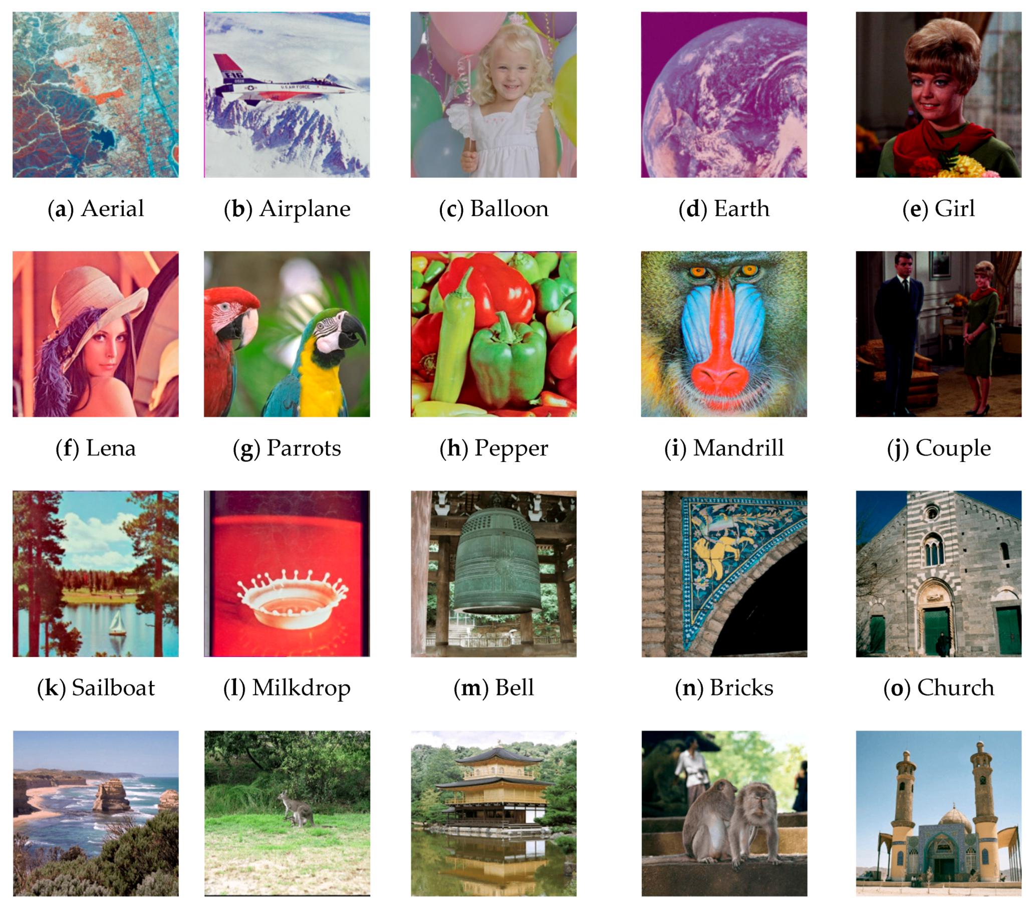
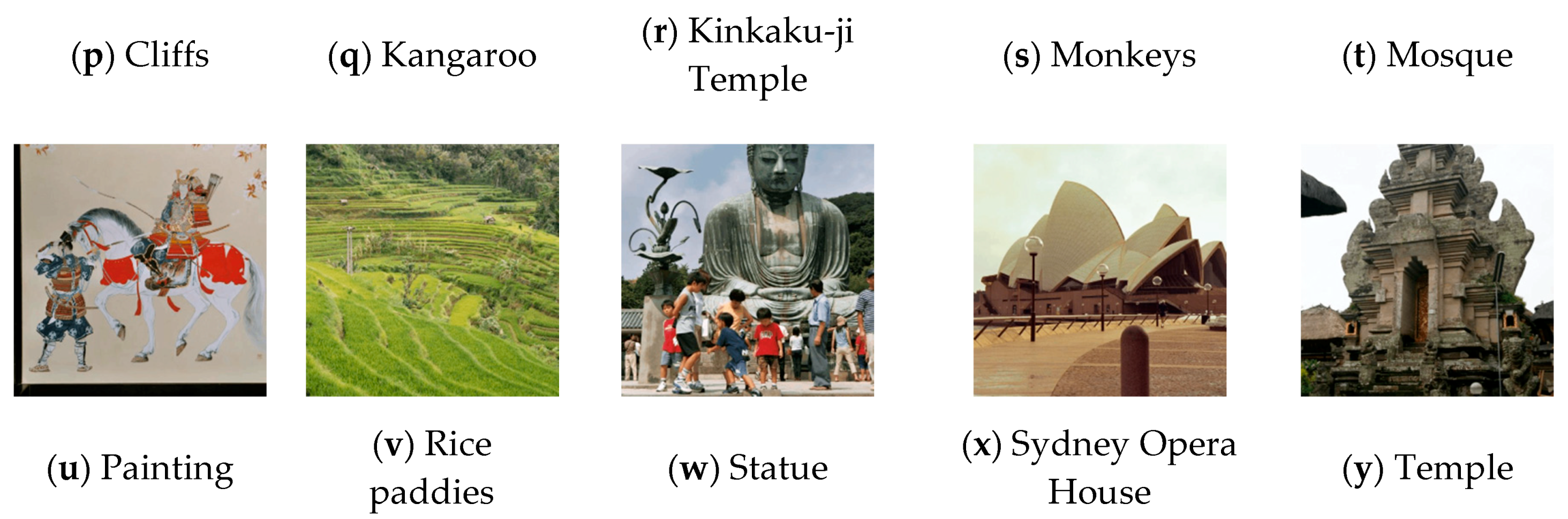
In the experiments, 25 images of in Figure 1 were used. These images were obtained from the Standard Image Database [26] or CBlR Image Database [27] and in the TIFF or JPG format. Photopea [18] was first used to resize and crop each image to , then Cloudconvert [18] was applied to convert TIFF (JPG) format into the GIF format. The embedded secret data were generated using a pseudorandom number generator. Image quality was measured using the peak signal-to-noise ratios (PSNRs). Chi-square attack, RS steganalysis, and embedding efficiency were used to measure the undetectability of a steganography method.
5.1. PSNR Comparisons
To demonstrate the effectiveness of our method, we conducted three experiments for comparing the image qualities of the proposed method with those of Imaizumi et al. [16] and Aryal et al. [17] under the same embedding capacity. The first two experiments assume that the location map needed by Imaizumi et al. and Aryal et al.’s methods is not embedded in the stego image, and it is sent through another channel. The third experiment assumes that the location map needed by Imaizumi et al. and Aryal et al.’s methods is embedded in the stego image; thus, the embedding capacity is reduced.
In the first experiment, Imaizumi et al.’s and the proposed methods with capacities of 15,000 and 30,000 bits were conducted. First, each image was divided into blocks, each of which has size . Then, each block was embedded bits, . Part of results is depicted in Table 3 and Table 4. These tables reveal that the image qualities of the proposed method were the best. This means that the proposed method actually has lower embedding distortion for each block such that each block can be used for data embedding. In the following, more details of explanation are described.
In Imaizumi et al.’s method, the palette is reordered; this increases the distance between two neighboring colors (i.e., two colors with index difference 1) when their indices are large. In data embedding, if one pixel’s color with index is replaced by color , then the index of is or . However, when is large, these two colors with the index difference of 1 may not be close; this increases the embedding distortion.
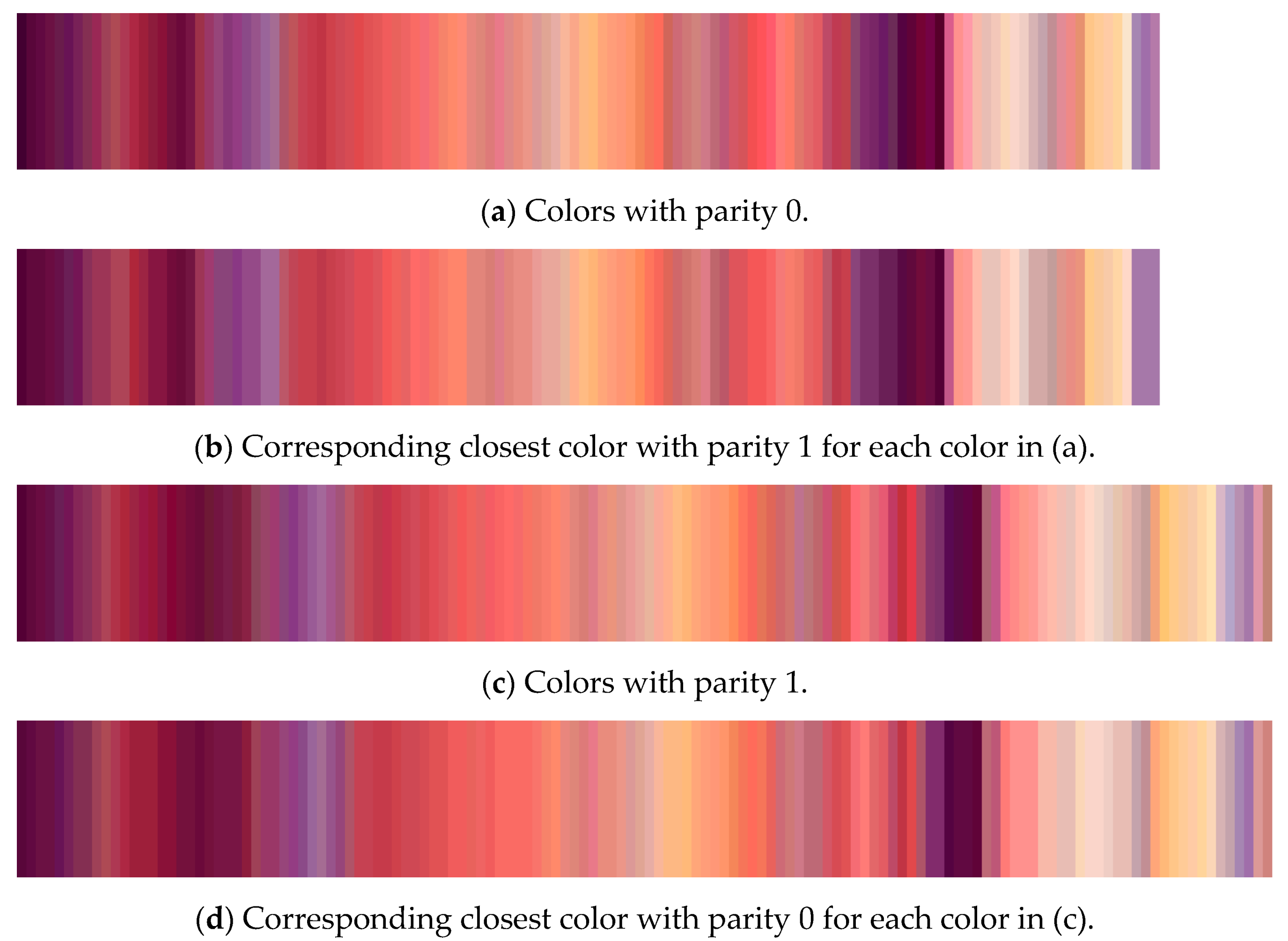
To provide more explanation, the image Lena was used with setting . Figure 2 illustrates the result of Tanaka et al.’s parity assignment. Figure 2a depicts all colors with parity 0, and Figure 2c illustrates all colors with parity 1. Figure 2b depicts the corresponding closest color with parity 1 of each color in Figure 2a. Figure 2d depicts the corresponding closest color with parity 0 of each color in Figure 2c. From these figures, we can determine that for each color with parity 0 (1), a similar color with parity 1 (0) can always be found.
Figure 3 illustrates the result of Imaizumi et al.’s palette reordering. Figure 3a displays the reordered color palette. Figure 3b denotes the best replacing one of each color in Figure 3a when embedding data. Figure 3c illustrates the enlarged part of the rectangle marked by red color in Figure 3a. Figure 3d depicts the enlarged part of the rectangle marked by red color in Figure 3b. These figures indicate that some colors may be replaced by an unsimilar color during data embedding.
In the second experiment, we compared the proposed method with the methods proposed by Imaizumi et al. [16] and Aryal et al. [17] with a capacity of 45,000 bits and . Note that for the image Couple, only 43,845 bits can be embedded using Aryal et al.’s method. Part of results is listed in Table 4, which reveals that the proposed method provides the best image quality under the same capacity. The reason is the same as that in experiment 1. Furthermore, our method modifies at most one pixel during data embedding; other methods [16,17] may modify more than one pixel during data embedding.
As mentioned previously, Imaizumi et al. and Aryal et al.’s methods need an extra location map to record which blocks are used for embedding, in experiment 3, the location map is embedded into a stego image. According to Table 2, the maximum valid embedding capacity of Imaizumi et al. and Aryal et al.’s methods are and , respectively. Table 5 shows part of image qualities of Imaizumi et al.’s, Aryal et al.’s, and our methods under the same embedding capacity. Note that to enforce embedding the location map in the first 4096 (5467) blocks for Imaizumi et al.’s (Aryal et al.’s) method, all indices 0 (255) of pixels in these blocks are changed to 1 (254) before embedding; this will avoid overflow/underflow after embedding. From these tables, we can see that image qualities of the proposed method are always superior to those of Imaizumi et al. and Aryal et al.’s methods under the same embedding capacity. The main reason is that embedding the location map will occupy several blocks and reduce the embedding capacity. Thus, under the same embedding capacity, those blocks used for embedding the location map in Imaizumi et al. and Aryal et al.’s methods will be skipped for data embedding in the proposed method. This will make the proposed method have higher image quality.
5.2. Chi-square Attack and RS Steganalysis
In steganography, the main goal for a stego image is statistically undetectable [21] (p. 52). To test whether the embedded images are detectable, chi-square attack [23], RS steganalysis [24], and embedding efficiency [21] were conducted. Chi-square attack and RS steganalysis are discussed in this section, and embedding efficiency in Section 5.3.
Each of chi-square attack and RS steganalysis has two experiments, one embedded bits () for Imaizumi et al.’s and the proposed methods. The other embedded bits () for Aryal et al.’s and the proposed methods.
Chi-square attack employs Pearson’s chi-square test to determine whether there is a statistically significant difference between the expected frequencies and the observed frequencies in one or more categories of an image, and it can detect whether a palette image is embedded by messages. The details of applying the chi-square attack to steganography methods are described as follows:
- Step 1:
- Let the palette indices of a palette image be divided into categories, each category contains a pair of indices (, ), , …, . Let and be the theoretically expected and observed frequencies of pixels with index after embedding messages, respectively. Then
- Step 2:
- The statistic is given as
- Step 3:
- Let represent the embedding probability, can be calculated by the following equation:
In chi-square attack, the results for three methods are ; this means that the three methods can resist chi-square attack. There are two reasons: (1) These three methods are block-based; the embedding capacities are limited and lower than 1 bpp; this will make chi-square attack fail [21]; (2) chi-square attack is used to detect LSB-based methods, but these three methods are not LSB-based methods.
Chi-square attack just uses sample counts and neglects spatial correlations among pixels in the stego image. Fridrich et al. [24] introduced RS steganalysis for detection of LSB embedding that utilizes sensitive dual statistics derived from spatial correlations in image.
In RS steganalysis, for a given image , through a given local mask, two flipping functions, and a discrimination function, all pixels of the image can be classified into three groups: Regular, singular, and unchanged. Given a non-negative mask , we can obtain the relative frequency of the regular group denoted as and the relative frequency of the singular group denoted as . Then through the mask , we can obtain the relative frequency of the regular group denoted as and the relative frequency of the singular group denoted as . Let be the embedding rate in f, RS steganalysis can estimate by solving the following equation:
where
and represents of a stego image with pixels embedded (i.e., the LSBs of pixels flipped from a cover image). Thus, we can obtain easily through f; furthermore, by flipping the LSB of each pixel in to get , we can also obtain through . , , and can be obtained by the similar way. Then, is calculated from the root of Equation (20), whose absolute value is smaller, by the following equation:
Two experiments are conducted, one for Imaizumi et al.’s [16] and the proposed methods uses block size and three capacities (23%, 46%, and 69%); the other for Aryal et al.’s [17] and the proposed methods uses block size and the same three capacities. In the experiments, the mask m is defined as . Table 6 and Table 7 show part of the s of Imaizumi et al.’s, Aryal et al.’s, and the proposed methods. Note that both Imaizumi et al. and Aryal et al.’s methods embedded message by reordering the original palette, so there are two results for their methods by analyzing the original and the reordering palettes. From these tables, we can see that RS steganalysis cannot estimate accurately. The reason is that these three methods are not LSB-based methods. We can conclude that the three methods can resist RS steganalysis and are undetectable.
5.3. Embedding Efficiency
Another measurement for undetectability is embedding efficiency [21]. The embedding efficiency is defined as the number of embedded random message bits per embedding change [21]. According to this definition, embedding efficiency () can be expressed as follows:
Methods with higher embedding efficiency are more undetectable, because under the same capacity, higher embedding efficiency methods will change less pixels than lower embedding efficiency methods. For , according to Equation (24), the estimated embedding efficiency of the proposed method () can be calculated by Equation (25).
where stands for the probability of pixel changed in a block, here and .
The estimated embedding efficiency of Imaizumi et al.’s method () can be calculated by Equation (26).
where stands for the probability of pixel changed in a block, here , , and .
The estimated embedding efficiency of Aryal et al.’s method () can be calculated by Equation (27).
where stands for the probability of unchanged, stands for the probability of pixels from {, } changed, here , , and .
Table 8 shows the estimated embedding efficiencies of the proposed, Imaizumi et al.’s [16], and Aryal et al.’s [17] methods obtained by using Equations (25–27). Table 9 shows part of experimental embedding efficiency calculated by applying Equation (24) to each stego image, which is obtained by one of Imaizumi et al.’s, Aryal et al.’s and the proposed methods. From these tables, we can see that either estimated embedding efficiency or experimental one, the proposed method has higher embedding efficiency than those of Imaizumi et al. and Aryal et al.’s methods. This means that the proposed method is less detectable than Imaizumi et al. and Aryal et al.’s methods.
6. Conclusions
As mentioned previously, some BBMs produce large embedding distortions in some blocks; a location map is incorporated into these methods to record which blocks are used for data embedding. This will reduce the embedding capacity for secret data. To avoid this disadvantage, in this paper, we have proposed a BBM for palette images. The method modifies at most one pixel in a block. If modification is required, one optimal pixel with minimal embedding distortion is selected; this makes each block be used to embed secret data; that is, the embedding capacity of the proposed method is larger than that of the state-of-the-art BBMs. As to the undetectability, chi-square attack, RS steganalysis, and the embedding efficiency are used. Imaizumi et al.’s, Aryal et al.’s., and the proposed methods can resist chi-square attack and RS steganalysis. However, through the measure of embedding efficiency, both estimated and experimental efficiencies revealed that our method provided higher undetectability.
Author Contributions
Conceptualization, H.-Y.W. and L.-H.C.; methodology, H.-Y.W. and L.-H.C.; software, H.-Y.W.; validation, H.-Y.W. and L.-H.C.; writing—Original draft preparation, H.-Y.W.; writing—Review and editing, H.-Y.W. and L.-H.C.; visualization, H.-Y.W. and L.-H.C.; supervision, L.-H.C. and Y.-T.C. All authors have read and agreed to the published version of the manuscript.
Funding
This research received no external funding.
Conflicts of Interest
The authors declare no conflict of interest.
References
- Zhang, X.; Sun, Z.; Tang, Z.; Yu, C.; Wang, X. High capacity data hiding based on interpolated image. Multimed. Tools Appl. 2016, 76, 9195–9218. [Google Scholar] [CrossRef]
- Hussain, M.; Wahid, A.; Ho, A.T.; Javed, N.; Jung, K.-H. A data hiding scheme using parity-bit pixel value differencing and improved rightmost digit replacement. Signal. Process. Image Commun. 2017, 50, 44–57. [Google Scholar] [CrossRef]
- Zhang, W.; Wang, S.; Zhang, X. Improving Embedding Efficiency of Covering Codes for Applications in Steganography. IEEE Commun. Lett. 2007, 11, 680–682. [Google Scholar] [CrossRef]
- Chang, C.; Chou, Y. Using nearest covering codes to embed secret information in gray scale images. In Proceedings of the 2nd International Conference on Ubiquitous Information Management and Communication, Suwon, Korea, 31 January–1 February 2008; Associaion for Computing Machinery (ACM): New York, NY, USA. [Google Scholar]
- Cao, Z.; Yin, Z.; Hu, H.; Gao, X.; Wang, L. High capacity data hiding scheme based on (7, 4) Hamming code. SpringerPlus 2016, 5, 175. [Google Scholar] [CrossRef] [PubMed] [Green Version]
- Guo, Y.; Cao, X.; Wang, R.; Jin, C. A new data embedding method with a new data embedding domain for JPEG images. In Proceedings of the 2018 IEEE Fourth International Conference on Multimedia Big Data (BigMM), Laguna Hills, CA, USA, 13–16 September 2018; Institute of Electrical and Electronics Engineers (IEEE): New York, NY, USA, 2018; pp. 1–5. [Google Scholar]
- Hong, W.; Zhou, X.; Lou, D.-C.; Chen, T.S.; Li, Y. Joint image coding and lossless data hiding in VQ indices using adaptive coding techniques. Inf. Sci. 2018, 245–260. [Google Scholar] [CrossRef]
- Hong, W.; Chen, T.S.; Yin, Z.; Luo, B.; Ma, Y. Data hiding in AMBTC images using quantization level modification and perturbation technique. Multimed. Tools Appl. 2016, 76, 3761–3782. [Google Scholar] [CrossRef]
- S-Tools. Available online: https://www.cs.vu.nl/~ast/books/mos2/zebras.html (accessed on 3 November 2020).
- Ez Stego. Available online: http://www.informatik.htw-dresden.de/~fritzsch/VWA/Source/EzStego.java (accessed on 3 November 2020).
- Fridrich, J. A new steganographic method for palette-based image. In Proceedings of the IS&T PICS Conference, Savannah, GA, USA, 25–28 April 1999. [Google Scholar]
- Fridrich, J.; Du, R. Secure steganographic methods for palette images. Comput. Vis. 2000, 1768, 47–60. [Google Scholar] [CrossRef]
- Tzeng, C.-H.; Yang, Z.-F.; Tsai, W.-H. Adaptive data hiding in palette images by color ordering and mapping with security protection. IEEE Trans. Commun. 2004, 52, 791–800. [Google Scholar] [CrossRef]
- Tanaka, G.; Suetake, N.; Uchino, E. A steganographic method realizing high capacity data embedding for palette-based images. In Proceedings of the International Workshop on Smart Info-Media Systems in Asia, Osaka, Japan, 22–23 October 2009. [Google Scholar]
- Imaizumi, S.; Ozawa, K. Multibit embedding algorithm for steganography of palette-based images. Lect. Notes Comp. Sci. 2014, 8333, 99–110. [Google Scholar] [CrossRef]
- Imaizumi, S.; Ozawa, K. Palette-based image steganography for high-capacity embedding. Bull. Soc. Photogr. Imag. Jpn. 2015, 25, 7–11. [Google Scholar]
- Aryal, A.; Motegi, K.; Imaizumi, S.; Aoki, N. Improvement of Multi-bit Information Embedding Algorithm for Palette-Based Images. Lecture Notes in Computer Science; Springer Science and Business Media LLC: Cham, Switzerland, 2015; Volume 9290, pp. 511–523. [Google Scholar]
- EVONIK. Available online: https://www.corporate.evonik.com/ (accessed on 3 November 2020).
- Miltner, K.M.; Highfield, T. Never gonna GIF you up: Analyzing the cultural significance of the animated GIF. Soc. Media + Soc. 2017, 3, 1–11. [Google Scholar] [CrossRef] [Green Version]
- Zhao, H.; Wang, H.; Khan, M.K. Steganalysis for palette-based images using generalized difference image and color correlogram. Signal. Process. 2011, 91, 2595–2605. [Google Scholar] [CrossRef]
- Cox, I.J.; Miller, M.L.; Bloom, J.A.; Fridrich, J.; Kalker, T. Applications and Properties. In Digital Watermarking and Steganography, 2nd ed.; Morgan Kaufmann: San Francisco, CA, USA, 2007; pp. 49–56. [Google Scholar]
- Crandall, R. Some Notes on Steganography. Posted on Steganography Mailing List. 1998. Available online: http://dde.binghamton.edu/download/Crandall_matrix.pdf (accessed on 29 May 2018).
- Westfeld, A.; Pfitzmann, A. Attacks on steganographic systems breaking the steganographic utilities EzStego, Jsteg, Steganos, and S-Tools. Lec. Notes. Comput. Sci. 2000, 1768, 61–75. [Google Scholar]
- Fridrich, J.; Goljan, M. Practical steganalysis of digital images: State of the art. Electron. Imaging 2002 2002, 4675, 1–13. [Google Scholar] [CrossRef]
- ISO/CIE 11664-6:2014 (Formerly CIE S 0146/E:2013). Colorimetry—Part 6: CIEDE2000 Colour-Difference Formula; CIE Central Bureau: Vienna, Austria, 2014. [Google Scholar]
- Standard Image Database (SIDBA). Available online: http://www.ess.ic.kanagawa-it.ac.jp/app_images_j (accessed on 7 October 2018).
- CBlR Image Database. Available online: http://imagedatabase.cs.washington.edu/groundtruth/ (accessed on 3 October 2020).
Figure 1.
Twenty-five test images.


Figure 2.
Results of Tanaka et al.’s parity assignment with for Lena.

Figure 3.
Results of Imaizumi et al.’s palette reordering for Lena.


Table 1.
Relation between secret data w and ().
| (3 Bits) | ||
|---|---|---|
| 7 (111) | 0 | 3 |
| 6 (110) | 0 | 2 |
| 5 (101) | 0 | 1 |
| 4 (100) | 0 | 0 |
| 3 (011) | 1 | 0 |
| 2 (010) | 1 | 1 |
| 1 (001) | 1 | 2 |
| 0 (000) | 1 | 3 |
Table 2.
The comparisons of embedding capacities among Imaizumi et al.’s [16], Aryal et al.’s [17], and the proposed methods for image size and .
| Block Size | ||||
|---|---|---|---|---|
| Embedding Method | [16] | Proposed Method | [17] | Proposed Method |
| Total Block number () | 16,384 | 21,845 | ||
| Location map size ( bits) | 12,288 | 0 | 16,383 | 0 |
| Block number needed for record location map () | 4096 | 0 | 5461 | 0 |
| Number of available blocks for secret data embedding () | 12,288 | 16,384 | 16,384 | 21,845 |
| Maximum embedding capacity (bits) | 36,864 | 49,152 | 49,152 | 65,535 |
Table 3.
Peak signal-to-noise ratios (PSNRs) of Imaizumi et al.’s [16] and the proposed methods.
Table 3.
Peak signal-to-noise ratios (PSNRs) of Imaizumi et al.’s [16] and the proposed methods.
| Capacity (Bits) | ||||
|---|---|---|---|---|
| [16] | Proposed Method | [16] | Proposed Method | |
| Aerial | 38.78 | 41.99 | 36.71 | 39.31 |
| Airplane | 46.29 | 47.18 | 42.95 | 44.09 |
| Balloon | 45.10 | 48.04 | 42.14 | 44.14 |
| Earth | 43.70 | 50.61 | 42.45 | 47.22 |
| Girl | 42.57 | 43.33 | 39.40 | 40.12 |
| Lena | 41.51 | 45.21 | 39.17 | 41.89 |
| Parrots | 40.22 | 42.22 | 37.05 | 38.54 |
| Pepper | 41.42 | 42.53 | 38.02 | 39.17 |
| Mandrill | 38.82 | 40.34 | 35.81 | 37.30 |
| Couple | 41.44 | 46.16 | 39.77 | 43.18 |
| Sailboat | 40.62 | 43.96 | 38.24 | 40.76 |
| Milkdrop | 45.61 | 47.47 | 42.09 | 43.35 |
Table 4.
PSNRs of Imaizumi et al.’s [16], Aryal et al.’s [17], and the proposed methods with a capacity 45,000 bits and .
| Block Size | ||||
|---|---|---|---|---|
| [16] | Proposed Method | [17] | Proposed Method | |
| Bell | 34.39 | 41.45 | 37.51 | 41.13 |
| Bricks | 36.00 | 35.44 | 34.97 | 36.95 |
| Church | 36.21 | 42.07 | 38.06 | 41.29 |
| Cliffs | 33.28 | 39.51 | 36.05 | 39.50 |
| Kangaroo | 36.53 | 40.31 | 32.63 | 39.99 |
| Kinkaku-ji Temple | 34.60 | 38.61 | 34.66 | 38.54 |
| Monkeys | 36.08 | 39.53 | 34.87 | 39.99 |
| Mosque | 37.42 | 40.38 | 38.70 | 40.03 |
| Painting | 35.94 | 41.79 | 37.58 | 41.47 |
| Rice paddies | 36.18 | 41.18 | 36.46 | 40.93 |
| Statue | 30.79 | 39.28 | 35.25 | 38.77 |
| Sydney Opera House | 40.18 | 43.87 | 39.07 | 43.80 |
| Temple | 40.22 | 40.38 | 36.39 | 40.51 |
| Block Size | ||||
|---|---|---|---|---|
| Capacity | ||||
| [16] | Proposed Method | [17] | Proposed Method | |
| Aerial | 33.07 | 38.35 | 29.22 | 36.91 |
| Airplane | 37.05 | 42.62 | 34.96 | 40.66 |
| Balloon | 35.82 | 42.13 | 33.78 | 40.52 |
| Earth | 38.94 | 45.60 | 39.14 | 43.99 |
| Girl | 33.53 | 38.89 | 30.55 | 37.33 |
| Lena | 34.34 | 40.30 | 32.52 | 38.61 |
| Parrots | 31.60 | 36.52 | 29.86 | 34.97 |
| Pepper | 32.72 | 37.58 | 30.72 | 36.05 |
| Mandrill | 30.81 | 35.91 | 27.00 | 34.25 |
| Couple | 35.48 | 41.76 | 32.75 | 40.16 |
| Sailboat | 33.92 | 39.52 | 31.18 | 37.99 |
| Milkdrop | 35.58 | 40.99 | 33.50 | 39.20 |
Table 6.
The results of RS steganalysis for Imaizumi et al.’s [16] and the proposed methods with block size .
Table 6.
The results of RS steganalysis for Imaizumi et al.’s [16] and the proposed methods with block size .
| Method | Proposed Method | Imaizumi et al. | Imaizumi et al. | |||||||||
|---|---|---|---|---|---|---|---|---|---|---|---|---|
| Palette | Original | Original | Reordering | |||||||||
| 0 | 1 | 2 | 3 | 0 | 1 | 2 | 3 | 0 | 1 | 2 | 3 | |
| Actual embedding rate (%) | ||||||||||||
| 0 | 23 | 46 | 69 | 0 | 23 | 46 | 69 | 0 | 23 | 46 | 69 | |
| Estimated embedding rate (%) | ||||||||||||
| Aerial | 0 | -3 | -5 | 1 | 0 | 10 | 10 | 16 | −20 | 10 | 18 | 32 |
| Airplane | −16 | −1 | 2 | 8 | −16 | −37 | −56 | −80 | −9 | −12 | −5 | −9 |
| Balloon | −11 | −19 | −17 | −20 | −11 | −14 | −12 | −21 | 7 | 6 | 0 | 3 |
| Earth | −18 | −12 | −12 | −16 | −18 | −23 | −28 | −26 | 21 | 14 | 14 | −15 |
| Girl | 12 | −23 | −18 | −30 | 12 | 10 | −4 | −7 | −16 | −8 | −18 | −19 |
| Lena | 0 | 12 | 11 | 12 | 0 | 2 | −9 | −4 | 4 | 6 | 10 | 8 |
| Parrots | 11 | −1 | 1 | 2 | 11 | 12 | 11 | 15 | −9 | −6 | −7 | −6 |
| Pepper | −1 | 11 | 11 | 11 | −1 | −1 | −3 | −2 | 4 | 2 | 6 | −4 |
| Mandrill | 0 | 0 | 0 | −1 | 0 | 3 | 8 | −11 | 5 | 10 | 9 | 7 |
| Couple | −11 | −2 | −11 | −7 | −11 | 5 | −12 | −4 | −16 | 20 | 18 | 22 |
| Sailboat | 11 | −15 | −25 | −24 | 11 | 12 | 10 | 5 | −12 | −12 | −9 | −12 |
| Milkdrop | 15 | 10 | 10 | 13 | 15 | 14 | 18 | 14 | −1 | 2 | 0 | −1 |
Table 7.
The results of RS steganalysis for Aryal et al.’s [17] and the proposed methods with block size .
Table 7.
The results of RS steganalysis for Aryal et al.’s [17] and the proposed methods with block size .
| Method | Proposed Method | Aryal et al. | Aryal et al. | |||||||||
|---|---|---|---|---|---|---|---|---|---|---|---|---|
| Palette | Original | Original | Reordering | |||||||||
| 0 | 3 | 3 | 3 | 0 | 3 | 3 | 3 | 0 | 3 | 3 | 3 | |
| Actual embedding rate (%) | ||||||||||||
| 0 | 23 | 46 | 69 | 0 | 23 | 46 | 69 | 0 | 23 | 46 | 69 | |
| Estimated embedding rate (%) | ||||||||||||
| Bell | −11 | −11 | −11 | −13 | −11 | −16 | −15 | −19 | −12 | −17 | −16 | −10 |
| Bricks | −27 | −39 | −55 | −39 | −27 | −28 | −31 | −46 | 5 | 0 | 1 | −9 |
| Church | 11 | 11 | 15 | 17 | 11 | 11 | 14 | 16 | 4 | 4 | 4 | −2 |
| Cliffs | −9 | −12 | −19 | −20 | −9 | −7 | −6 | −4 | 2 | 1 | 0 | 2 |
| Kangaroo | −40 | −46 | −40 | −43 | −40 | −52 | −60 | −75 | −39 | −44 | −47 | −43 |
| Kinkaku−ji Temple | −15 | −16 | −24 | −31 | −15 | −19 | −25 | −30 | 4 | 2 | −1 | −4 |
| Monkeys | 4 | 5 | 5 | 8 | 4 | 0 | −6 | −9 | −2 | −2 | 2 | 3 |
| Mosque | −15 | −11 | −10 | −8 | −15 | −14 | −17 | −19 | −2 | −2 | 0 | 8 |
| Painting | −11 | −13 | −19 | −22 | −11 | −12 | −22 | −35 | −5 | −9 | −13 | −17 |
| Rice paddies | −148 | −143 | −144 | −158 | −148 | −151 | −138 | −131 | −54 | −40 | −39 | −38 |
| Statue | 18 | 16 | 17 | 18 | 18 | 23 | 25 | 29 | −9 | −8 | −11 | −4 |
| Sydney Opera House | 1 | −2 | −6 | −7 | 1 | −2 | 1 | −2 | 8 | 14 | 15 | 17 |
| Temple | −18 | −16 | −14 | −17 | −18 | −48 | −50 | −45 | 6 | 11 | 15 | 13 |
Table 8.
Estimated embedding efficiencies of Imaizumi et al.’s [16], Aryal et al.’s [17], and the proposed methods with .
| Block Size | ||||
|---|---|---|---|---|
| Methods | [16] | Proposed Method | [17] | Proposed Method |
| 1.406 | 3.428 | 1.909 | 3.428 | |
Table 9.
Experimental embedding efficiencies of Imaizumi et al.’s [16], Aryal et al.’s [17], and the proposed methods with .
| Block Size | |||||
|---|---|---|---|---|---|
| Capacity (Bits) | 49152 | 65535 | |||
| Methods | [16] | Proposed Method | [17] | Proposed Method | |
| Images | |||||
| Aerial | 1.492 | 3.417 | 2.006 | 3.442 | |
| Airplane | 1.499 | 3.415 | 1.994 | 3.431 | |
| Balloon | 1.497 | 3.430 | 1.999 | 3.423 | |
| Earth | 1.500 | 3.415 | 1.994 | 3.425 | |
| Girl | 1.490 | 3.454 | 2.007 | 3.450 | |
| Lena | 1.491 | 3.412 | 1.996 | 3.431 | |
| Parrots | 1.496 | 3.445 | 1.988 | 3.424 | |
| Pepper | 1.482 | 3.401 | 2.011 | 3.427 | |
| Mandrill | 1.507 | 3.434 | 2.015 | 3.442 | |
| Couple | 1.482 | 3.432 | 2.012 | 3.440 | |
| Sailboat | 1.505 | 3.425 | 1.996 | 3.427 | |
| Milkdrop | 1.500 | 3.411 | 1.993 | 3.442 | |
Publisher’s Note: MDPI stays neutral with regard to jurisdictional claims in published maps and institutional affiliations. |
© 2020 by the authors. Licensee MDPI, Basel, Switzerland. This article is an open access article distributed under the terms and conditions of the Creative Commons Attribution (CC BY) license (http://creativecommons.org/licenses/by/4.0/).
Share and Cite
MDPI and ACS Style
Wu, H.-Y.; Chen, L.-H.; Ching, Y.-T. Block-Based Steganography Method Using Optimal Selection to Reach High Efficiency and Capacity for Palette Images. Appl. Sci. 2020, 10, 7820. https://0-doi-org.brum.beds.ac.uk/10.3390/app10217820
AMA Style
Wu H-Y, Chen L-H, Ching Y-T. Block-Based Steganography Method Using Optimal Selection to Reach High Efficiency and Capacity for Palette Images. Applied Sciences. 2020; 10(21):7820. https://0-doi-org.brum.beds.ac.uk/10.3390/app10217820
Chicago/Turabian StyleWu, Han-Yan, Ling-Hwei Chen, and Yu-Tai Ching. 2020. "Block-Based Steganography Method Using Optimal Selection to Reach High Efficiency and Capacity for Palette Images" Applied Sciences 10, no. 21: 7820. https://0-doi-org.brum.beds.ac.uk/10.3390/app10217820
Note that from the first issue of 2016, this journal uses article numbers instead of page numbers. See further details here.