Article

4D Printing of Origami Structures for Minimally Invasive Surgeries Using Functional Scaffold

1
School of Engineering, University of Liverpool, Liverpool L69 3BX, UK
2
School of Engineering, University of Birmingham, Birmingham B15 2TT, UK
3
Drug Discovery, Delivery and Patient Care (DDDPC), School of Life Sciences, Pharmacy and Chemistry, Kingston University London, Kingston Upon Thames, Surrey KT1 2EE, UK
4
School of Engineering, Technology, and Design, Canterbury Christ Church University, Canterbury CT1 1QU, UK
*
Author to whom correspondence should be addressed.
Submission received: 21 November 2020 / Revised: 22 December 2020 / Accepted: 28 December 2020 / Published: 31 December 2020

Abstract

:
Origami structures have attracted attention in biomedical applications due to their ability to develop surgical tools that can be expanded from a minimal volume to a larger and functional device. On the other hand, four-dimensional (4D) printing is an emerging technology, which involves 3D printing of smart materials that can respond to external stimuli such as heat. This short communication introduces the proof of concept of merging origami and 4D printing technologies to develop minimally invasive delivery of functional biomedical scaffolds with high shape recovery. The shape-memory effect (SME) of the PLA filament and the origami designs were also assessed in terms of deformability and recovery rate. The results showed that herringbone tessellation origami structure combined with internal natural cancellous bone core satisfies the design requirement of foldable scaffolds. The substantial and consistent SME of the 4D printed herringbone tessellation origami, which exhibited 96% recovery compared to 61% for PLA filament, was the most significant discovery of this paper. The experiments demonstrated how the use of 4D printing in situ with origami structures could achieve reliable and repeatable results, therefore conclusively proving how 4D printing of origami structures can be applied to biomedical scaffolds.

1. Introduction

Bone is a complex structure that is made up of several constitutes such as fibres, cells, and minerals. This structure is far different from other human tissues; the extracellular cells are mineralised, which gives it significant mechanical strength and stiffness. As a result, it plays a significant role to support the body structure and allows the movement of the skeleton [1]. Several medical problems can lead to the loss or the damage of human bones, such as disease, trauma, and injury which requires medical treatment. Bone repair, regeneration or replacement can be achieved by tissue replacement from one human body site to another (autograft) or from one person to another (allograft). Although these procedures have been well established and have shown excellent results, major issues for both techniques include being painfully expensive, constrained, and subject to infection or body rejection in case of an allograft [2]. Bone scaffolds represent a favourable alternative to autograft and allograft techniques. They are used as a template for cell attachment, proliferation, and differentiation to promote bone regeneration. Bone scaffolds require being biocompatible, biodegradable, strong, and porous to promote the flow of body fluid [3,4]. However, placing current scaffold designs can require highly invasive surgery, which is often required so that there is space to place what can be large and bulky scaffolds. Scaffold insertion can be particularly damaging to the patient depending on where it is being placed. Minimally invasive surgery is associated with fewer complications, less pain, shorter hospital stay, as well as the cosmetic benefit of reducing post-surgery scars. Implementing minimally invasive surgery in bone scaffold treatment requires smart scaffolds that can be deformed before insertion and then recover once in position so that smaller points of incision would be required.
Additive manufacturing (AM) or 3D printing is the manufacturing of a 3D object layer by layer from a digital design. There are several categories of AM technologies, such as powder bed fusion, material extrusion, direct energy deposition, vat photo polymerisation, binder jetting, sheet lamination, and material jetting. Material extrusion is a low cost, easy to use technique and available in many commercial forms [5,6]. In material extrusion, the material is extruded under pressure through a nozzle according to a digital design. The extruded material is deposited on top of each layer and solidifies. Fused deposition modelling (FDM) is a technique of material extrusion where a thermoplastic filament is softened by heaters and extruded from a nozzle, whereas pneumatic or syringe extrusion (PE/SE) techniques extrude paste materials such as ceramic clays. The vat polymerisation (VP) technique uses UV to initiate the cross-linking of a layer of photosensitive resin to cure it into a solid polymer. Afterwards, another layer of the polymer is deposited and cured onto the past layers until the part is completed. VP techniques include stereolithography (SLA), continuous liquid interface production (CLIP), digital light processing (DLP), and photon polymerisation [7,8,9,10]. The technique has been adopted to fabricate polymer and ceramic micro parts for MEMS applications as it outperformed the conventional soft lithography processes that are limited to fabricate 2.5 D parts and not real 3D components [11,12,13,14,15,16,17]. Powder bed fusion (PBF) is an approach in which a laser beam selectively scans a layer of the powder according to a digital design to build components in the typical layer-wise way [18,19]. In direct energy deposition (DED), a laser or electron beam is focused on melting metal powder. The molten droplets are then deposited on the top of a substrate. Laser energy net shaping (LENS), laser deposition welding (LDW), and wire and arc AM (WAAM) are widely used techniques of DED [20,21,22]. In binder jetting, the powder is bound by spraying binder droplets from a jet on top of a layer of powder, then the powder platform is lowered to apply another layer on top of the first layer [23,24,25]. Sheet lamination (SL) cuts and glues layers of materials by using a laser or ultrasonic beam to bond the stacked layers. Additional machining and surface finishing are typically used after 3D printing [26,27]. In material jetting (MJ), droplets of the materials are deposited and dried or cured layer by layer. There are different ways to deposit the material such as in continuous inkjet, in which the material is deposited with the aid of continuous pressure [28,29], and drop on demand (DOD), which uses discrete pressure instead of continuous pressure [30]. Additive manufacturing has the ability to process a wide range of materials such as metals [31], polymers [32], and ceramics [4]. The technology has been adopted in many industries, such as aerospace [33,34], biomedical [35], defence [36], and energy [37]. Four-dimensional (4D) printing is an emerging technology that refers to the additive manufacture of material that responds to changes in its immediate environment, therefore enabling engineered solutions to be recovered without direct human or computer interaction. The technology was first introduced in 2013 and since then has attracted great attention in many biomedical applications. Four-dimensional printing offers several benefits, such as the ability to produce smart products from smart material, change of product geometry when required, and adding innovation in the design and development stage [36]. These benefits enabled the penetration of this technology to broad applications in engineering, dentistry, medicine,, and material sciences.
Shape-memory polymers are stimuli-responsive polymers that can change their shape from one to another by the use of heat, light, or electricity. The thermally induced shape-memory effect present in specific polymers is due to shape recovery of polymers when subject to heat. The chains in the amorphous polymers are completely dispersed randomly in the matrix without the restriction of crystallites in semicrystalline polymers. On the other hand, movements of the polymer segments are frozen in the case of the glassy state. The rubber-elastic state starts when increasing the activation energy, which initiates the rotation around the segment bonds. This enables the polymer chains to take up energetically equivalent shapes with compact random macromolecules. The rubbery state occurs above the glass transition temperature (Tg), and the polymer becomes flexible. The original shape of the polymer can be recovered when it is plastically deformed only upon heating to above Tg. In this case, physical or chemical cross-link works to store the elastic energy during shape programming and the driving recovery force [38]. The presence of shape-switching part nodes or shape-fixing parts in polylactic acid polymers (PLAs) is behind the shape recovery. Both physical cross-links and the crystallisation of PLAs act as net points and therefore have shape-memory ability. However, the shape-memory effect of PLA polymers is often restricted to minor deformations since breaks occur when programming PLA with more than 10% deformation. This limits the potential for using PLA in minimally invasive surgeries [39].
This communication introduces a design and manufacturing approach to develop deployable scaffolds using 4D printing of shape-memory polymer (SMP) that will be inserted into a cavity in the body through minimally invasive surgery. Once in position, the scaffold will be recovered, causing it to increase in size and fill the cavity where it will substitute as the tissue’s extracellular matrix (ECM). The ECM coordinates how cells coordinate with each other as well as providing overall structure to a tissue. An engineered tissue scaffold replicates a diseased or damaged tissue’s ECM temporarily when a native ECM is not present. Scaffolds are used to aid the recovery of a patient when a cavity in the tissue would prohibit the normal regeneration of the tissue. Therefore, a scaffold will be inserted into a cavity to substitute as the ECM so that healthy cells may migrate and proliferate across it, filling the cavity. The primary focus of this paper was not on the biomedical interaction between cells and the scaffold but was instead on achieving the benefit of SMP and smart structures in tissue engineering and to introduce the proof of concept of deployable biomedical scaffolds using origami structures.

2. Design and Experimental Setup
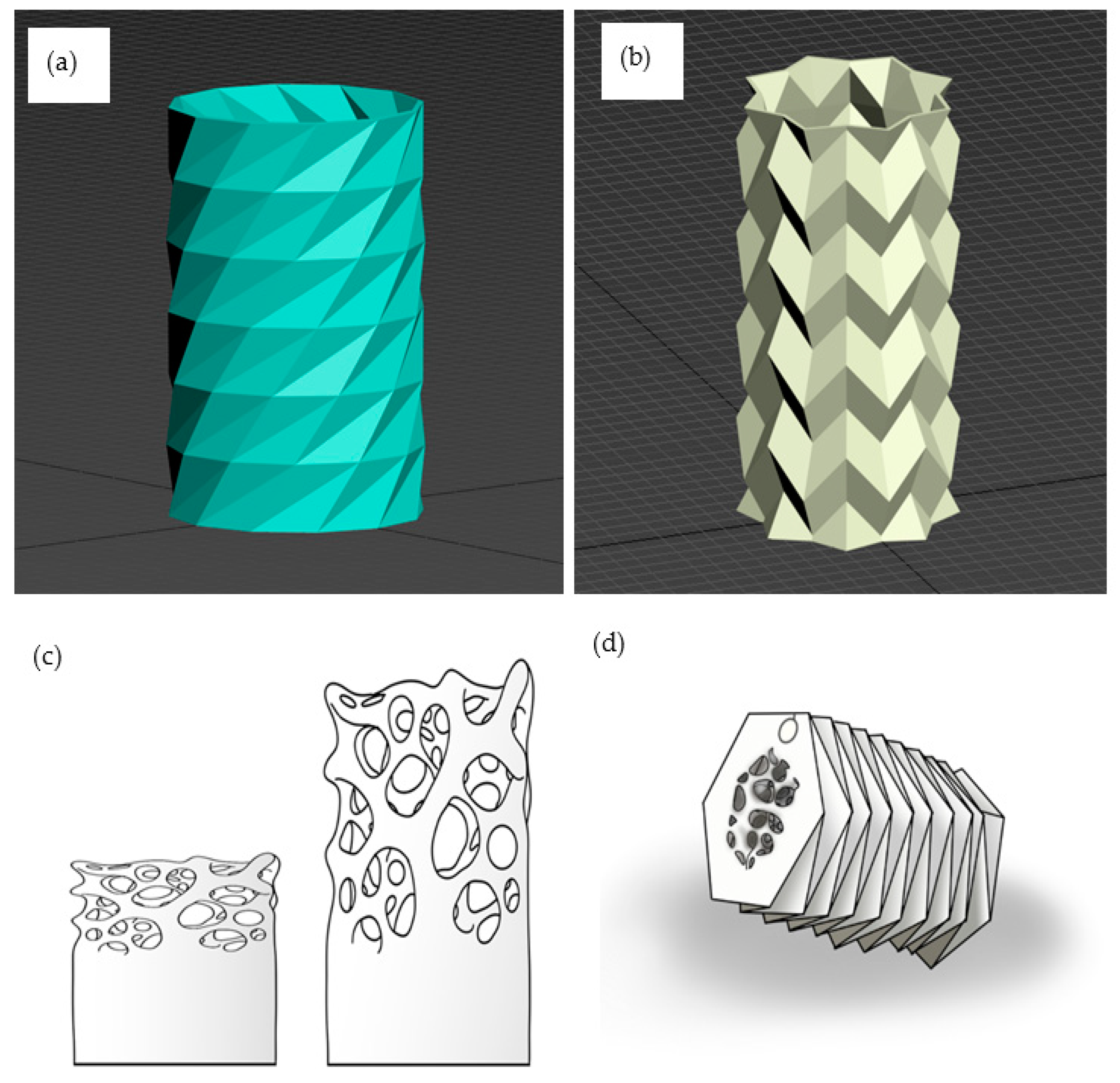
There are multiple types of additive manufacturing and processed materials. However, this study employs FDM as it the most common method to process polylactic acid (PLA). PLA lends itself particularly well to medical applications since it is biodegradable, biocompatible, non-toxic, and an eco-friendly polymer [40]. Therefore, it has full clearance to be used as a material for medical implants by both the European Medical Agency (EMA) and the Federal Drug Administration (FDA). In addition to its ability to be used for implants, it is a shape-memory polymer (SMP), meaning PLA can be 4D printed.

2.1. Origami Design

Origami tessellations are origami-folding patterns that repeat themselves and therefore can be scaled up and down depending on application, with the potential of the fold being infinitely repeated. Different tessellations are enabled for acute management of pre- and post-shape recovery as well as how the polymer would origami-move between the states [41,42]. The design of the scaffolds was split into microstructure and macrostructure design. The microstructure design was concerned with how the scaffold’s pores are shaped, sized, and arranged to promote cell differentiation, migration, and proliferation, whereas the macrostructure was concerned with the design of a recovered scaffold. The primary consideration of the macrostructure was to replicate bone morphology while simultaneously employing origami techniques to exploit the SME of PLA.
Origami herringbone and waterbomb tessellation designs were considered in this study, as shown in Figure 1a,b. The tessellations were curved around on themselves to create a tube. As recovery occurs, the cavity in the middle grows and so accurately represents the medullary cavity found in many long bones. By far the most significant benefit of this design is the substantial difference in volume between recovered and collapsed forms Figure 1c shows how compressing what is already very similar in structure to real cancellous bone will close the gaps between replicated trabeculae, allowing for a smaller geometry before recovery. Almost all bones have a section of compact bone with a cancellous bone interior. Therefore, this kind of scaffold would be highly transferable between different bones within the body. There are two potential problems with this design. First, the size difference between deformed and recovered form is not as significant as in other designs. Secondly, and most importantly, this design does not offer a great solution to reducing the size of the scaffold that needs to substitute for compact bone. The combination of an origami design for the outer edges of the scaffold, which would substitute for compact bone, and the porous replica of cancellous bone to fill the centre, is shown in Figure 1d. This merger of designs eliminates the weaknesses of the individual designs to create a solution that will meet the needs of the patient and surgeon.

2.2. Fabrication and Characterisation

The as-received PLA filaments (PLA, MakerBot, Brooklyn, USA) were tested first using a standard dynamic-mechanical analyser (DMA, New Castle, UK) to investigate the effect of the heating temperature on the storage modulus. Dynamic mechanical analysis (DMA) was generally used to assess the polymer’s viscoelastic properties as they changed from glassy to rubbery-like characteristics. Filaments with 0.7 mm in diameter were cut to a length of 15 cm and attached to the dynamic-mechanical analyser at a frequency of 1 Hz and heated from 25 to 90 °C.
Two properties are associated with shape-memory polymers. These are shape fixity and shape recovery. Shape fixity is the ability of the switching points to fix the temporary shape, whereas shape recovery measures the ability of SMPs to recover their original shape. Many SMPs such as PLA have high shape fixity but poor shape recovery, as the material cannot generate sufficient recovery force. We focused this research to measure the shape recovery of PLA filament to understand the material characteristics independently of the design influence. PLA filament with 1.75 mm diameter was cut into 30 × straight test samples of 100 mm length, Figure 2a. Samples were placed in the slit in threes and heated to the melt temperature of 200 °C. Due to all polymer cross-links breaking at this temperature, the samples straightened out under their weight. Once removed and allowed to cool, samples were ready for the experiment. Samples were heated to just above the Tg of approximately 60–65 °C in a water bath of 70 °C, shown in Figure 2b. The reason for using a water bath with a temperature higher than the Tg was so tested samples would not fall below the glass transition temperature when they were taken out of the water for deformation. Samples were taken out individually and deformed to a range of predetermined angles and allowed to cool. Once cooled back to room temperature, each sample angle was remeasured because it was common that the angle achieved was a few degrees off the intended angle. Samples were then re-submerged in the water bath at 70 °C, and the shape-memory effect was observed. After only a few seconds, the samples would start returning to their original programmed straight form. Within no more than 10 s, the shape-memory effect was over. Once the SME was complete, the samples could cool. The recovery angle of each sample was measured. The difference between the recovered angle and the actual test angle was calculated as a percentage of the actual test angle, Figure 2c,d. This percentage shows how much the geometry recovered..
The tubular and the modified herringbone tessellation origami structures were 3D printed using MakerBot Replicator 2. PLA 1.75 mm filament was used as the feeding stock in the 3D printer. The objects were printed with 0.15 mm layer thickness at 100 mm in height, 60 mm in diameter and with a 2.5 mm wall thickness from PLA to produce the prototypes. Similarly to the SME measurements of the PLA filament, the models were characterised in terms of the deformation and recovery to test how the SME would affect the behaviour of the two origami models. The aim was to realise the most significant and consistent SME possible, but this time within the whole models. Another aspect of the experiment was whether the 61.5% recovery found in PLA filament was a reproducible percentage recovery figure for origami folds.
The printed objects were subject to a compressive force and twisted torque causing deformation by heating to just above the Tg of approximately 60–65 °C in a water bath at 70 °C. The reason for using a water bath with a temperature higher than the Tg was so tested samples would not fall below the Tg when they were taken out of the water for deformation. The prototypes were removed one at a time from the water bath and deformed. Twisted torque and compression load with the aid of a G-clamp were used because they meant that the load could be kept on the prototypes as they were allowed to cool. The deformation amount was determined by when the folds had fully folded in on themselves. Once cooled back to room temperature, each deformed prototype was measured to calculate the ratio between initial print size and deformation size. Samples were then resubmerged in the water bath at 70 °C, and the shape-memory effect was observed. Once the SME was complete, the samples were removed from the bath and allowed to cool. The difference between the recovered geometry and the deformed geometry was calculated as a percentage of the deformed geometry.

3. Results and Discussion

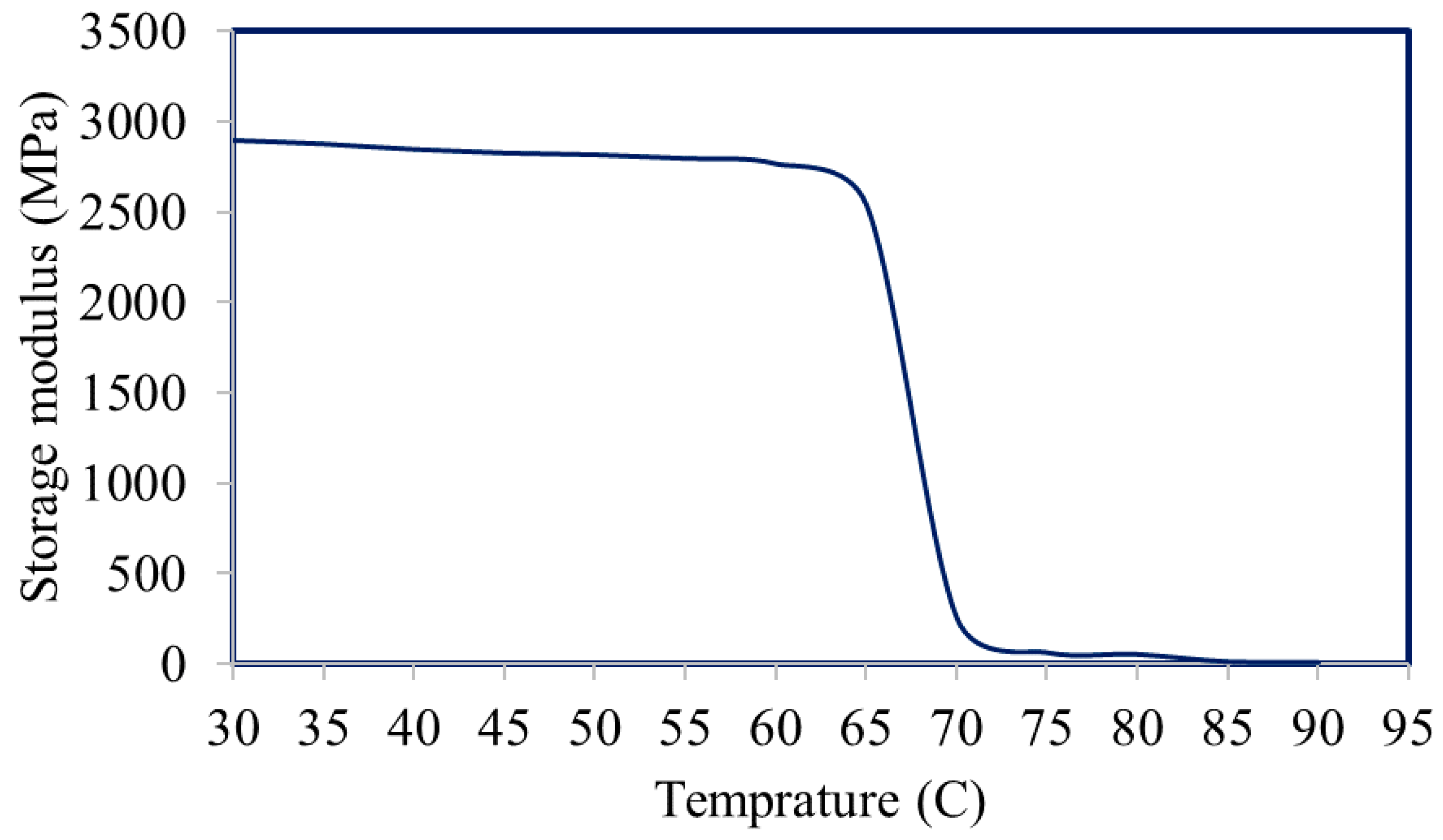
3.1. Dynamic Mechanical Thermal Properties of the PLA Filaments

Figure 3 shows the dynamic mechanical thermal properties of the PLA filaments when heated from 25 to 90 °C. The as-received filaments show a near plateau storage modulus over temperature range from 30 to 65 °C, at which point it dropped sharply afterwards where it changed from the glassy to the rubbery state.

3.2. Deformation and Shape Recovery of the PLA Filaments

The recovery behaviour of the PLA filaments, both the deformed and the recovered, is shown in Table 1, Table 2 and Table 3. There was an expectation that the results would show decreasing rates of recovery as the intended test angle was increased. This expectation was due to higher forces being applied to achieve the greater angle deformations. This expectation was shown to be incorrect, as shown in Table 1 and Table 2. In fact, the results of the experiment showed no correlation between changes in the intended test angle and the percentage recovered. The lack of correlation would have significant implications for future scaffold designs. The result showed that PLA polymer recover around 61.5% with SD of 4.3% regardless of the bending angle.

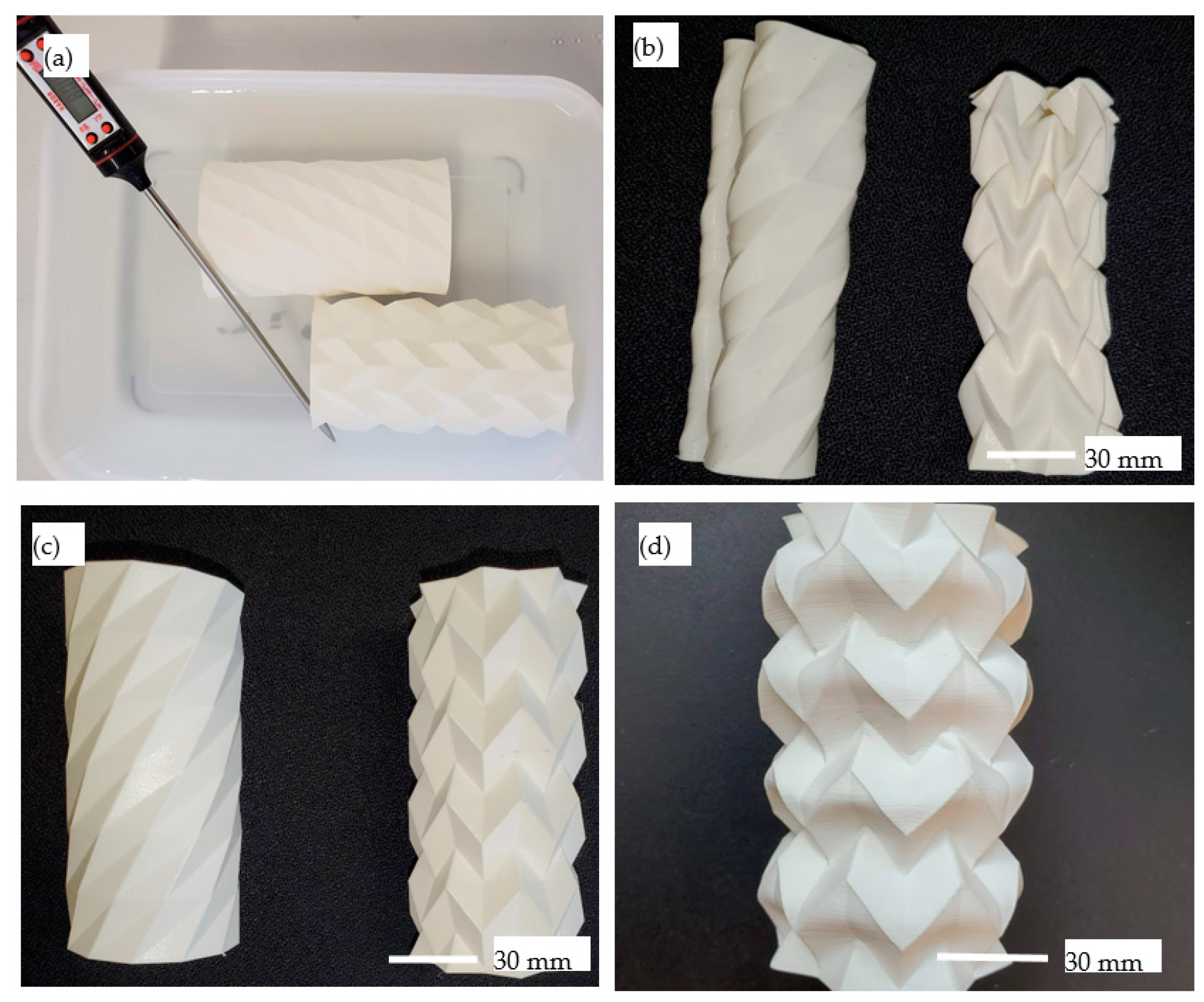
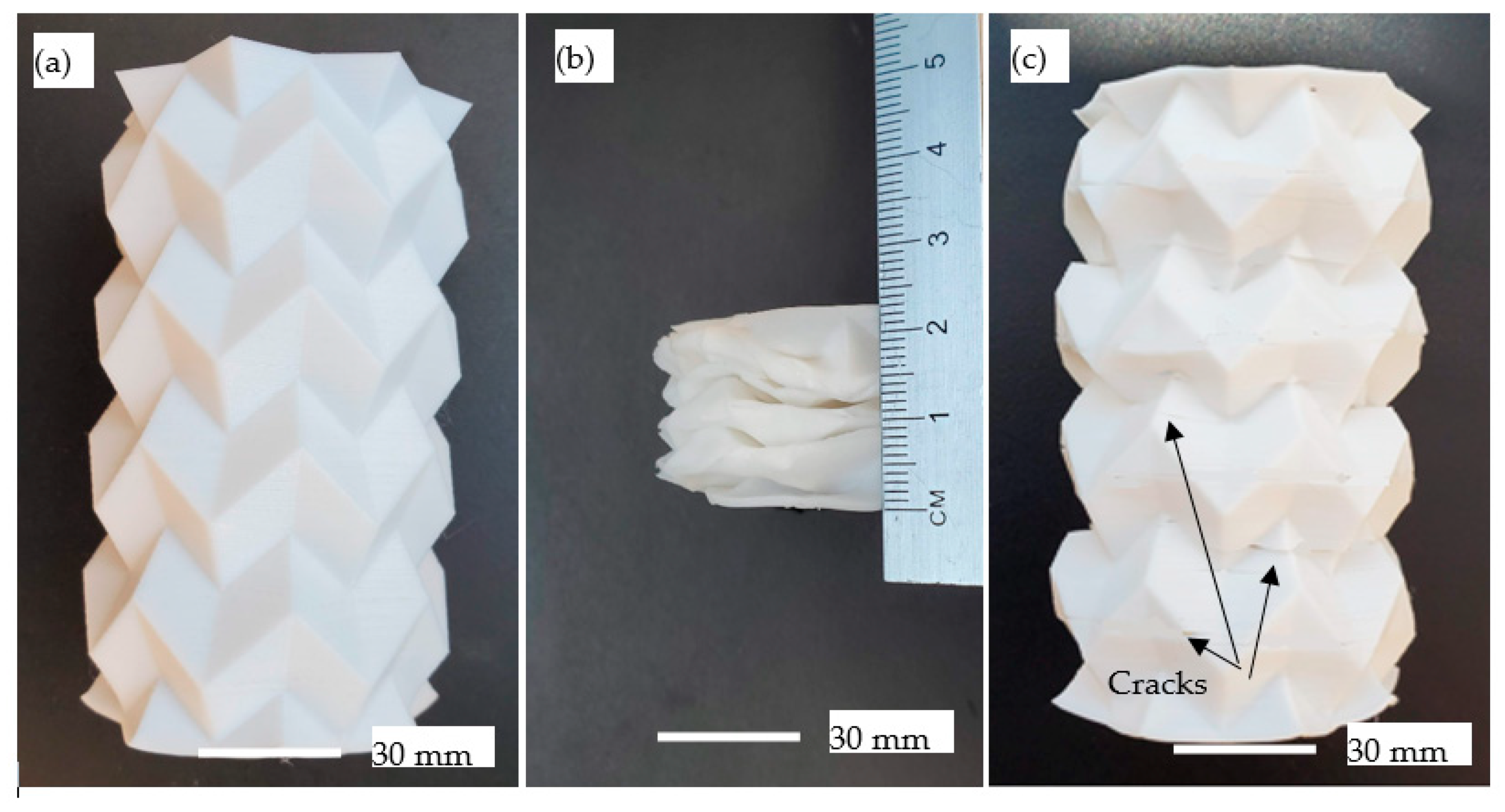
3.3. Deformation and Shape Recovery of the Origami Tessellations

The two herringbone and waterbomb tessellation origami structures after twisting and recovery are shown in Figure 4. The most significant find from the measurement of the deformation and recovery of the two herringbone and waterbomb tessellation origami structures was that the expected recovery of approximately 65.1% of each angular fold, suggested by the results of the PLA filament result, was not exhibited. The angle recovery was far greater than that shown by the filament test samples in the first experiment. Recovery rates had a mean average of 96% for the two test samples. All independent variables have been kept constant, except for the geometry of the test samples. Therefore, it can be deduced that the geometry of the origami induced internal stresses within the two models, which aided the SME and explain why greater recovery rates were observed. The twisted waterbomb tessellation origami structures did not deform in the intended direction. The recovery of the tubular models still achieved a result that was 96% of the initial print geometry; however, because the deformation of the waterbomb tessellation origami structure was unpredictable, it did not meet the requirements of the biomedical scaffold, and so it was discounted as a potential biomedical scaffold to be taken forward. Only the herringbone models were now left as the tessellation type to be taken forward. Figure 4d shows the herringbone models after being deformed and recovered.
To better evaluate how herringbone tessellation origami could deform and be recovered, the experiment was repeated. The difference was that this time the direction of deformation was changed from twisting to compression along the central axis. The amount of deformation observed without structural failure was far more significant. The deformation took the height from 100 to 25 mm. The recovery rate for this test was again 96%, though several cracks were observed. This direction of deformation and recovery was repeated on the same herringbone sample several times, and the rate of recovery remained at 96% each time, causing the tube to decrease in recovered height each time the test was repeated. Edges became softer each time the test was repeated, as shown in Figure 5.
The scaffold interior for substituting cancellous bone was embedded to the herringbone tessellation origami to replicate cancellous bone and to validate its deformation and recovery behaviour. Each thin strand of the scaffold crossing the scaffold core replicates an individual trabecula. Trabeculae have a similar cross-sectional microstructure to osteons; however, Haversian canals do not pass through their centre. Therefore, the central core does not require blood vessels to pass through the replica trabeculae. The requirements of the central core’s macrostructure were near enough the same as the outer compact bone substitute section of the scaffold. The only real difference was that the density of the central core needed to be less to create the large pores visible in cancellous bone. The herringbone tessellation origami was combined with the central core to create the final CAD model, shown in Figure 6a. Figure 6b shows the 3D printed sample with the porous central core. The figure shows how light can pass through the cancellous scaffold substitute, proving that the pores are interconnected.
The same SME procedure was applied to the process using herringbone tessellation origami and substituting the cancellous core, and the results are shown in Figure 7. Unsurprisingly, the amount that the model deformed was considerably less than that of the tubular prototypes shown in Figure 5 due to the substantial increase in stiffness of the central core. Despite this, the scaffold was deformed to 70 mm and then recovered to 95 mm, as shown in Figure 7. All previous experiments had been testing individual aspects of the developed design to optimise the SME for when combined into the final design. Therefore, this was the first test exploring the SME of a full scaffold prototype, and it was relatively successful, though the deformation was less than that of the tubular models. Future investigations will consider the effect of parameters such as layer thickness and building directions on the SME.

4. Conclusions

A novel concept of deployable scaffolds using a combination of origami and 4D printing technologies was introduced. The design strategy applied in the paper is based on the creation of porous origami structures in nearly final shape and deformed into a volume suitable for minimal invasion surgeries. We characterised the shape-memory behaviour of the PLA material and the manufactured designs. We characterised the shape-memory behaviour of the PLA filaments and the manufactured designs. The PLA filaments showed a constant shape recovery of about 61% regardless of the deformation amount. On the other hand, tubular herringbone tessellation origami showed significant deformation capabilities and a high recovery rate of about 96% despite the presence of cracks in the deformed samples. The same recovery rate was achieved when adding porous natural cancellous bone core to the herringbone tessellation origami, though the deformation amount was less significant. Future studies are recommended to characterise the mechanical and biocompatible properties that are needed for the clinical adoption of this approach. The use of 4D printing in situ with origami structures is relatively inexpensive and easy to implement, which makes it also suitable for the development of a wide range of foldable structures.

Author Contributions

Conceptualization, H.H.; methodology, T.L.; validation, H.H. and T.L.; formal analysis, H.H., A.E., K.E. and T.L.; investigation, T.L. and A.M.; writing—original draft preparation, T.L., H.H., and A.M.; writing—review and editing, K.E. and A.E.; supervision, H.H., K.E. and A.E. All authors have read and agreed to the published version of the manuscript.

Funding

This research received no external funding.

Data Availability Statement

Data is contained within the article.

Conflicts of Interest

The authors declare no conflict of interest.

References

  1. Lacroix, D. 4-Biomechanical aspects of bone repair. In Bone Repair Biomaterials; Planell, J.A., Best, S.M., Lacroix, D., Merolli, A., Eds.; Woodhead Publishing: Cambridge, UK, 2009; pp. 106–118. [Google Scholar] [CrossRef]
  2. Hasegawa, K.; Turner, C.H.; Burr, D.B. Contribution of collagen and mineral to the elastic anisotropy of bone. Calcif. Tissue Int. 1994, 55, 381–386. [Google Scholar] [CrossRef]
  3. Elsayed, M.; Ghazy, M.; Youssef, Y.; Essa, K. Optimization of SLM process parameters for Ti6Al4V medical implants. Rapid Prototyp. J. 2019, 25, 433–447. [Google Scholar] [CrossRef] [Green Version]
  4. Essa, K.; Hassanin, H.; Attallah, M.M.; Adkins, N.J.; Musker, A.J.; Roberts, G.T.; Tenev, N.; Smith, M. Development and testing of an additively manufactured monolithic catalyst bed for HTP thruster applications. Appl. Catal. A Gen. 2017, 542, 125–135. [Google Scholar] [CrossRef] [Green Version]
  5. Ngo, T.D.; Kashani, A.; Imbalzano, G.; Nguyen, K.T.Q.; Hui, D. Additive manufacturing (3D printing): A review of materials, methods, applications and challenges. Compos. Part B Eng. 2018, 143, 172–196. [Google Scholar] [CrossRef]
  6. Chaunier, L.; Guessasma, S.; Belhabib, S.; Della Valle, G.; Lourdin, D.; Leroy, E. Material extrusion of plant biopolymers: Opportunities & challenges for 3D printing. Addit. Manuf. 2018, 21, 220–233. [Google Scholar] [CrossRef]
  7. Liu, W.; Wu, H.; Tian, Z.; Li, Y.; Zhao, Z.; Huang, M.; Deng, X.; Xie, Z.; Wu, S. 3D printing of dense structural ceramic microcomponents with low cost: Tailoring the sintering kinetics and the microstructure evolution. J. Am. Ceram. Soc. 2019, 102, 2257–2262. [Google Scholar] [CrossRef]
  8. Zheng, X.; Lee, H.; Weisgraber, T.; Shusteff, M.; DeOtte, J.; Duoss, E.; Kuntz, J.; Biener, M.; Ge, Q.; Jackson, J.; et al. Ultralight, Ultrastiff Mechanical Metamaterials. Science 2014, 344, 1373–1377. [Google Scholar] [CrossRef] [Green Version]
  9. Ha, Y.-M.; Choi, J.-W.; Lee, S. Mass production of 3-D microstructures using projection microstereolithography. J. Mech. Sci. Technol. 2008, 22, 514–521. [Google Scholar] [CrossRef]
  10. Behroodi, E.; Latifi, H.; Najafi, F. A compact LED-based projection microstereolithography for producing 3D microstructures. Sci. Rep. 2019, 9, 19692. [Google Scholar] [CrossRef] [Green Version]
  11. Hassanin, H.; Jiang, K. Multiple replication of thick PDMS micropatterns using surfactants as release agents. Microelectron. Eng. 2011, 88, 3275–3277. [Google Scholar] [CrossRef]
  12. Hassanin, H.; Jiang, K. Net shape manufacturing of ceramic micro parts with tailored graded layers. J. Micromech. Microeng. 2013, 24, 015018. [Google Scholar] [CrossRef]
  13. Hassanin, H.; Jiang, K. Fabrication and characterization of stabilised zirconia micro parts via slip casting and soft moulding. Scr. Mater. 2013, 69, 433–436. [Google Scholar] [CrossRef]
  14. Hassanin, H.; Jiang, K. Functionally graded microceramic components. Microelectron. Eng. 2010, 87, 1610–1613. [Google Scholar] [CrossRef]
  15. Hassanin, H.; Jiang, K. Alumina composite suspension preparation for softlithography microfabrication. Microelectron. Eng. 2009, 86, 929–932. [Google Scholar] [CrossRef]
  16. Hassanin, H.; Jiang, K. Fabrication of Al2O3/SiC Composite Microcomponents using Non-aqueous Suspension. Adv. Eng. Mater. 2009, 11, 101–105. [Google Scholar] [CrossRef]
  17. Hassanin, H.; Jiang, K. Optimized process for the fabrication of zirconia micro parts. Microelectron. Eng. 2010, 87, 1617–1619. [Google Scholar] [CrossRef]
  18. Murr, L.E. Metallurgy principles applied to powder bed fusion 3D printing/additive manufacturing of personalized and optimized metal and alloy biomedical implants: An overview. J. Mater. Res. Technol. 2020, 9, 1087–1103. [Google Scholar] [CrossRef]
  19. Chatham, C.A.; Long, T.E.; Williams, C.B. A review of the process physics and material screening methods for polymer powder bed fusion additive manufacturing. Prog. Polym. Sci. 2019, 93, 68–95. [Google Scholar] [CrossRef]
  20. Bose, S.; Banerjee, D.; Shivaram, A.; Tarafder, S.; Bandyopadhyay, A. Calcium phosphate coated 3D printed porous titanium with nanoscale surface modification for orthopedic and dental applications. Mater. Des. 2018, 151, 102–112. [Google Scholar] [CrossRef]
  21. Shivaram, A.; Bose, S.; Bandyopadhyay, A. Understanding long-term silver release from surface modified porous titanium implants. Acta Biomater. 2017, 58, 550–560. [Google Scholar] [CrossRef]
  22. Balla, V.K.; Das, M.; Bose, S.; Janaki Ram, G.D.; Manna, I. Laser surface modification of 316 L stainless steel with bioactive hydroxyapatite. Mater. Sci. Eng. C 2013, 33, 4594–4598. [Google Scholar] [CrossRef] [PubMed]
  23. Mostafaei, A.; Elliott, A.M.; Barnes, J.E.; Li, F.; Tan, W.; Cramer, C.L.; Nandwana, P.; Chmielus, M. Binder jet 3D printing–Process parameters, materials, properties, and challenges. Prog. Mater. Sci. 2020. [Google Scholar] [CrossRef]
  24. Ziaee, M.; Crane, N.B. Binder jetting: A review of process, materials, and methods. Addit. Manuf. 2019, 28, 781–801. [Google Scholar] [CrossRef]
  25. Lv, X.; Ye, F.; Cheng, L.; Fan, S.; Liu, Y. Binder jetting of ceramics: Powders, binders, printing parameters, equipment, and post-treatment. Ceram. Int. 2019, 45, 12609–12624. [Google Scholar] [CrossRef]
  26. Zhang, Y.; Jarosinski, W.; Jung, Y.-G.; Zhang, J. 2-Additive manufacturing processes and equipment. In Additive Manufacturing; Zhang, J., Jung, Y.-G., Eds.; Butterworth-Heinemann: Oxford, UK, 2018; pp. 39–51. [Google Scholar] [CrossRef]
  27. Mohammed, A.; Elshaer, A.; Sareh, P.; Elsayed, M.; Hassanin, H. Additive Manufacturing Technologies for Drug Delivery Applications. Int. J. Pharm. 2020, 580, 119245. [Google Scholar] [CrossRef]
  28. Goole, J.; Amighi, K. 3D printing in pharmaceutics: A new tool for designing customized drug delivery systems. Int. J. Pharm. 2016, 499, 376–394. [Google Scholar] [CrossRef]
  29. Derby, B. Additive Manufacture of Ceramics Components by Inkjet Printing. Engineering 2015, 1, 113–123. [Google Scholar] [CrossRef] [Green Version]
  30. Derby, B. Inkjet Printing of Functional and Structural Materials: Fluid Property Requirements, Feature Stability, and Resolution. Annu. Rev. Mater. Res. 2010, 40, 395–414. [Google Scholar] [CrossRef]
  31. Qiu, C.; Adkins, N.J.E.; Hassanin, H.; Attallah, M.M.; Essa, K. In-situ shelling via selective laser melting: Modelling and microstructural characterisation. Mater. Des. 2015, 87, 845–853. [Google Scholar] [CrossRef]
  32. Klippstein, H.; Hassanin, H.; Diaz De Cerio Sanchez, A.; Zweiri, Y.; Seneviratne, L. Additive Manufacturing of Porous Structures for Unmanned Aerial Vehicles Applications. Adv. Eng. Mater. 2018, 20, 1800290. [Google Scholar] [CrossRef]
  33. Essa, K.; Khan, R.; Hassanin, H.; Attallah, M.M.; Reed, R. An iterative approach of hot isostatic pressing tooling design for net-shape IN718 superalloy parts. Int. J. Adv. Manuf. Technol. 2016, 83, 1835–1845. [Google Scholar] [CrossRef] [Green Version]
  34. Galatas, A.; Hassanin, H.; Zweiri, Y.; Seneviratne, L. Additive Manufactured Sandwich Composite/ABS Parts for Unmanned Aerial Vehicle Applications. Polymers 2018, 10, 1262. [Google Scholar] [CrossRef] [PubMed] [Green Version]
  35. Hassanin, H.; Finet, L.; Cox, S.C.; Jamshidi, P.; Grover, L.M.; Shepherd, D.E.T.; Addison, O.; Attallah, M.M. Tailoring selective laser melting process for titanium drug-delivering implants with releasing micro-channels. Addit. Manuf. 2018, 20, 144–155. [Google Scholar] [CrossRef] [Green Version]
  36. Li, S.; Hassanin, H.; Attallah, M.M.; Adkins, N.J.E.; Essa, K. The development of TiNi-based negative Poisson’s ratio structure using selective laser melting. Acta Mater. 2016, 105, 75–83. [Google Scholar] [CrossRef] [Green Version]
  37. Sabouri, A.; Yetisen, A.K.; Sadigzade, R.; Hassanin, H.; Essa, K.; Butt, H. Three-Dimensional Microstructured Lattices for Oil Sensing. Energy Fuels 2017, 31, 2524–2529. [Google Scholar] [CrossRef] [Green Version]
  38. Lendlein, A.; Kelch, S. Shape-Memory Polymers. Angew. Chem. Int. Ed. 2002, 41, 2034–2057. [Google Scholar] [CrossRef]
  39. Xu, J.; Song, J. 10-Polylactic acid (PLA)-based shape-memory materials for biomedical applications. In Shape Memory Polymers for Biomedical Applications; Yahia, L.H., Ed.; Woodhead Publishing: Cambridge, UK, 2015; pp. 197–217. [Google Scholar] [CrossRef]
  40. Pawar, R.; Tekale, S.; Shisodia, S.; Totre, J.; Domb, A. Biomedical Applications of Poly(Lactic Acid). Recent Pat. Regen. Med. 2014, 4. [Google Scholar] [CrossRef]
  41. Chen, Y.; Yan, J.; Feng, J. Geometric and Kinematic Analyses and Novel Characteristics of Origami-Inspired Structures. Symmetry 2019, 11, 1101. [Google Scholar] [CrossRef] [Green Version]
  42. Uomini, N.; Lawson, R. Effects of Handedness and Viewpoint on the Imitation of Origami-Making. Symmetry 2017, 9, 182. [Google Scholar] [CrossRef] [Green Version]
Figure 1. CAD drawings of (a) herringbone tessellation origami, (b) waterbomb tessellation origami, (c) natural cancellous bone, and (d) combined tessellation origami and natural cancellous bone design.
Applsci 11 00332 g001
Figure 2. (a) Preparing polylactic acid (PLA) samples; (b) 70 °C water bath heating test samples; (c) one sample’s deformed shape; (d) recovered shape.
Applsci 11 00332 g002
Figure 3. Dynamic mechanical thermal properties of the PLA filaments.
Applsci 11 00332 g003
Figure 4. (a) The 70 °C water bath for heating waterbomb (up) and herringbone (down) tessellation origami structures. (b) After deformation, (c) after recovery, (d) herringbone tessellation after being deformed and recovered for the fourth time.
Applsci 11 00332 g004
Figure 5. (a) As-printed herringbone tessellation origami (b) after compression, and (c) after recovery.
Applsci 11 00332 g005
Figure 6. (a) Design of the central core, and (b) 3D printed of herringbone tessellation origami with substituting cancellous core.
Applsci 11 00332 g006
Figure 7. (a) As-printed herringbone tessellation origami with porous core (b) after compression, and (c) after recovery.
Applsci 11 00332 g007
Table 1. Deformed PLA test samples.
Repeat 1Repeat 2Repeat 3Repeat 4Repeat 5
30° Applsci 11 00332 i001 Applsci 11 00332 i002 Applsci 11 00332 i003 Applsci 11 00332 i004 Applsci 11 00332 i005
60° Applsci 11 00332 i006 Applsci 11 00332 i007 Applsci 11 00332 i008 Applsci 11 00332 i009 Applsci 11 00332 i010
90° Applsci 11 00332 i011 Applsci 11 00332 i012 Applsci 11 00332 i013 Applsci 11 00332 i014 Applsci 11 00332 i015
120° Applsci 11 00332 i016 Applsci 11 00332 i017 Applsci 11 00332 i018 Applsci 11 00332 i019 Applsci 11 00332 i020
150° Applsci 11 00332 i021 Applsci 11 00332 i022 Applsci 11 00332 i023 Applsci 11 00332 i024 Applsci 11 00332 i025
180° Applsci 11 00332 i026 Applsci 11 00332 i027 Applsci 11 00332 i028 Applsci 11 00332 i029 Applsci 11 00332 i030
Table 2. Recovered PLA test samples.
Repeat 1Repeat 2Repeat 3Repeat 4Repeat 5
30° Applsci 11 00332 i031 Applsci 11 00332 i032 Applsci 11 00332 i033 Applsci 11 00332 i034 Applsci 11 00332 i035
60° Applsci 11 00332 i036 Applsci 11 00332 i037 Applsci 11 00332 i038 Applsci 11 00332 i039 Applsci 11 00332 i040
90° Applsci 11 00332 i041 Applsci 11 00332 i042 Applsci 11 00332 i043 Applsci 11 00332 i044 Applsci 11 00332 i045
120° Applsci 11 00332 i046 Applsci 11 00332 i047 Applsci 11 00332 i048 Applsci 11 00332 i049 Applsci 11 00332 i050
150° Applsci 11 00332 i051 Applsci 11 00332 i052 Applsci 11 00332 i053 Applsci 11 00332 i054 Applsci 11 00332 i055
180° Applsci 11 00332 i056 Applsci 11 00332 i057 Applsci 11 00332 i058 Applsci 11 00332 i059 Applsci 11 00332 i060
Table 3. The quantified results of the deformation and recovery of the PLA filaments.
Intended Test Angle30°60°90°120°150°180°
Repeat 1Actual test angle30°53°81°110°133°160°
Angle post-recovery122228425058
Percentage recovered60.0%58.5%65.4%61.8%62.4%63.8%
Repeat 2Actual test angle31°50°80°112°131°158°
Angle post-recovery152227325066
Percentage recovered51.6%56%66.3%71.4%61.8%58.2%
Repeat 3Actual test angle23°52°77°108°136°157°
Angle post-recovery82431375061
Percentage recovered65.2%53.8%59.7%65.7%63.2%61.1%
Repeat 4Actual test angle30°49°79°108°137°156°
Angle post-recovery141828405360
Percentage recovered53.3%63.3%64.6%63.0%61.3%61.5%
Repeat 5Actual test angle34°54°82°106°142°158°
Angle post-recovery132329414860
Percentage recovered61.8%57.4%64.6%61.3%66.2%62.0%
Publisher’s Note: MDPI stays neutral with regard to jurisdictional claims in published maps and institutional affiliations.

