
Textile-Based Coils for Inductive Wireless Power Transmission


1
German Institutes for Textile and Fiber Research Denkendorf, (DITF), 73770 Denkendorf, Germany
2
Institute for Textile and Fiber Technologies (ITFT), University of Stuttgart, 70569 Stuttgart, Germany
*
Author to whom correspondence should be addressed.
Appl. Sci. 2021, 11(9), 4309; https://0-doi-org.brum.beds.ac.uk/10.3390/app11094309
Submission received: 6 April 2021
/
Revised: 6 May 2021
/
Accepted: 7 May 2021
/
Published: 10 May 2021
(This article belongs to the Section Electrical, Electronics and Communications Engineering)
Abstract
:We developed and evaluated different textile-based inductive coils for near-field wireless power transmission. The technology uses electromagnetic induction for the contactless transfer of electrical energy. Therefore, we investigated various methods for the attachment of conductive materials on a textile-based material and the production of textile-based coils based on QI standard. Afterwards, the textile-based coils were examined and evaluated due to their specific quality characteristics. This happens by calculating the transmission quality and the maximum efficiency of the system which enables comparison of different coil systems and indicates the transmission efficiency of the systems.
1. Introduction
Digitization is changing the way we communicate, inform, and consume. This will be one of the reasons for a considerable increase in the demand of smart textiles and wearable computers in the future. The Leibniz Centre for European Economic Research (ZEW) estimated a quadrupling of the market volume of smart textiles is realistic between the years 2017 and 2022 [1]. It can be assumed, that Smart Textiles will be a part of our everyday life, soon. However, at the moment there is a lack of acceptance and trust in these new textiles and clothing. High prices and the laborious handling of the products might be reasons for that. Moreover, the non-textile components, that enable the smart functions to the textiles, can be annoying for the user because all electronic components must be removed before washing the clothing. Other disruptive factors are the higher weight, wear and tear on plug connections, and possible restrictions on movements due to rigid and inflexible elements in the textile, which can be significantly reduced by using textile components. A textile induction coil for contactless energy transmission in wearables can reduce the stiff electric components in the clothing [2,3].
Wireless charging means the contactless transfer of energy by electromagnetic induction over short distances. The functional principle of wireless charging is based on inductive coupling of two coils (L1 and L2). One of the coils acts as a transmitter (L1) and the other as a receiver (L2) [4]. The physical principle behind contactless power transmission is electromagnetic induction. This means that a time-varying current (alternating current, AC) flowing through a primary coil generates a time-varying magnetic field. The magnetic field of the primary coil partially passes through an immediately adjacent secondary coil. The magnetic field of the primary coil generates an induction voltage at the receiver coil and, when loaded, a time-varying current. Koo et al. [5] focused on the analysis of a textile coil sensor and how its position affects the heart rate measurements. An important part of the work was the development and fabrication of the textile inductive coil sensor. It enabled a continuous monitoring of the heart rate without any contacts. The coil was made out of a hybrid yarn of polyester with silver coating and it was stitched onto a non-conductive base material. The coil consisted of ten turns with a distance of 15 mm. The outer diameter of the coil was 66 mm and the inner diameter was 10 mm. The inductance of the coil was 3.5695 µH. The heart rate can be measured by the change of the coil inductance in relation to the change of the impedance inside the body [5].
Sun et al. [6] investigated the electrical characteristics of sewn, embroidered, laser cut, and printed induction coils for wireless power transmission. They used a reference coil design of the Qi standard called WE-WPCC TRASM Qi-A5. The embroidered coil was made of a silver coated yarn. The planned inductance of the coil was 10.47 µH which results in 16 turns. For the laser cut method, a conductive fabric from Kitronik was used, which is made of nylon and has a silver coating on the surface. The final coil had 14 turns, an inner diameter of 20 mm and an inductance of 8.89 µH. As a third variant, an induction coil was printed onto a carrier textile via screen printing. They used an electrically conductive pigment printing paste. According to the planned inductance of 10.52 µH, the coil had 16 turns. Furthermore, it was determined that the printed coil was not suitable for energy transfer due to the high coil resistance and insignificant conductivity. To detect a possible energy transfer, the embroidered coil was used as power receiver and coupled with a transmitter system. At the output they measured a voltage of 4.6 V, which confirmed an energy transfer [6].
Li et al. [7] focused on the development of a textile-based induction coil for contactless energy transfer. They printed various coil geometries on a textile substrate using the screen-printing method. Therefore, they used a thermally curing silver printing paste. The design of the coil geometry was based on the planned inductance and was based on the Qi standard. An inductive energy transfer could be realized. A power of max. 1.2 W power was detected with a voltage of 5 V [7].
There has been no practical implementation of inductive wireless power transmission in smart textiles. In our work, we would like to improve the energy transfer of the coils and examine the influence of the wire resistance of the coil on the possible energy transfer.
2. Materials and Methods
2.1. Materials
The materials need a sufficient electrical conductivity and thereby a low electrical resistance. The first material, ELITEX® I (ELITEX) from Imbut GmbH, is a silver-plated polyamide yarn coated with an insulating PVC coating. The yarn including insulation has a final fineness of about 4000 dtex. Compared to other conductive yarns, the ELITEX yarn has a relatively low electrical resistance of 5 Ω/m. Due to its thickness of the material, it cannot be used as a sewing or embroidery thread and is therefore only suitable for tailored wire placement (TWP) which means a modification of the tailored fiber placement (TFP) [8]. It focuses on depositing cables or wires onto a carrier material instead of fiber materials. In this process, the cable is deposited on the carrier material by an oscillating guide and fixed to the base material by stitching. A particular advantage of this method is the free deposition of wires in circles, arcs, and all directional angles. A three-dimensional deposition of the wires is also possible, which offers the user enormous design freedom [9].
The second yarn is Shieldex 235/36 dtex 2 ply HC+B (Shieldex 235), which is also a silver-coated polyamide yarn with 605 dtex. According to the manufacturer, the yarn has an electrical resistance of 80 Ω/m. The third yarn: Shieldex 117/17 dtex 2 ply HC+B (Shieldex 117), is also a silver-coated polyamide yarn. It has a count of 295 dtex and the electrical resistance is lower than 300 Ω/m. The next used yarn is a multifilament yarn made of polyester. In order to achieve electrical conductivity, the yarn is wound with two very fine copper threads, which are individually insulated with lacquer. Like the ELITEX®, the wrapping yarn is only suitable as a winding material in the TWP (Table 1).
Another possibility which we used for a TWP coil is the use of a lacquer strand out of copper (no. CLI 200/30) from BLOCK TRANSFORMATOREN. The strand consists in total of 30 individual wires, each 0.1 mm in diameter and with a cross-sectional area of 0.236 mm2 and a resistance of 0.07 Ω/m. The lacquer insulation is polyurethane-based. The manufacturer specifies 0.84 A as the current load, as well as a continuous heat resistance of 130 °C [10]. The printing paste no. 200-05 from Creative Materials Inc. is used to print the conductive structures. The silver printing paste consists of 84% silver and has a sheet resistance of 0.010 Ω/mm2.
2.2. Sample Production
Various manufacturing processes have been tested for the production of textile-based coils. For this purpose, a number of textile processes are available. The following methods are used:
- ▪
- tailored-wire placement (TWP),
- ▪
- embroidery with conductive yarns,
- ▪
- printing with conductive printing paste,
- ▪
- hand winding.
The materials ELITEX, the wrapping yarn and the copper strand cannot be used as embroidery yarns due to their rough and brittle structure. Moreover, they are too thick for the embroidery needles, because of its silver coating and the PVC insulation. Instead, the TWP is the more suitable method. In addition, the same materials are also suitable to produce hand-wound coils, because of their higher stiffness and deformable properties. The two Shieldex yarns are used as embroidery threads due to their fineness. The yarns can be used for patterning via various stitch types. The conductive printing paste is used in the screen-printing process.
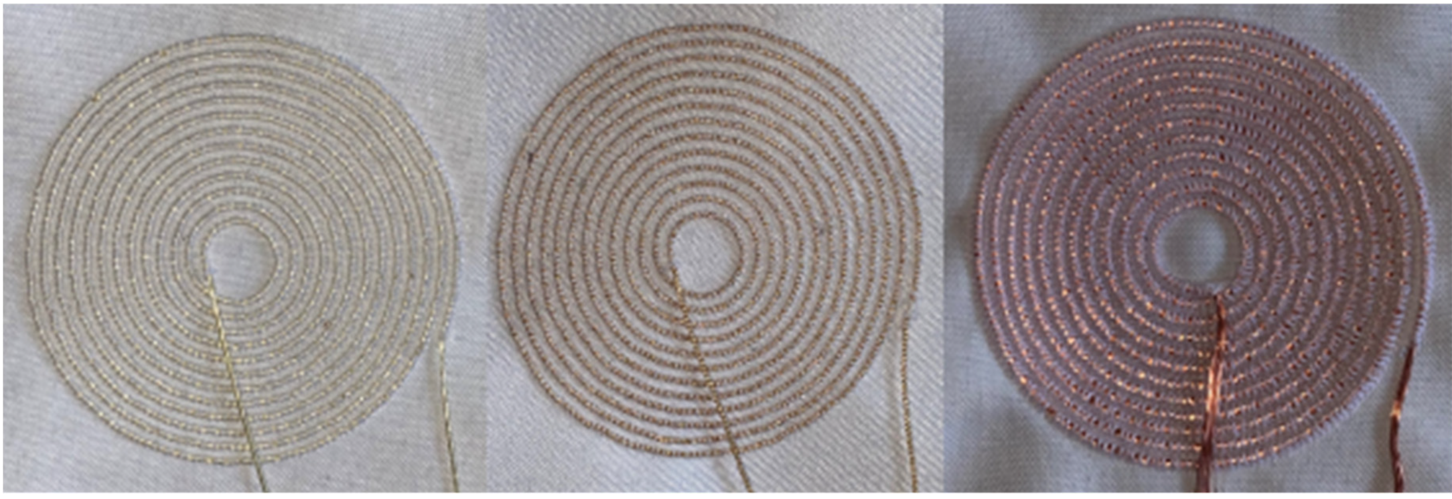
2.2.1. Embroidered Coils with Conductive Yarns
The first coils were embroidered onto a ground textile using a zigzag stitch (test series Z). The difficulty in processing the Shieldex yarns is to design the templates in such a way that a high stitch density can be achieved (Figure 1). At the same time, we have to ensure small gaps between the turns of a coil. However, due to the fact that Shieldex yarns do not have any insulation, the windings must not touch each other, otherwise there would be a short circuit at this point. We examined if there are any short circuits between the windings.
For initial trials five different coil sizes have been stitched, which had a varying number of turns. We also used different yarns and yarn combinations. The first embroidered coil (Z175) made out of Shieldex 235 has an outer diameter of 75 mm and consists of 10 turns. Both, upper thread and lower thread were made of the yarn. The track width of the windings was 2 mm each. The second coil (Z275) out of Shieldex 235 had a diameter of 75 mm and also 10 turns, the track width was 2 mm. The next bobbin (Z375) had an outer diameter of 75 mm, 10 turns. It consisted of Shieldex 117 in the upper thread, a non-conductive polyester yarn of similar fineness was used as the lower thread. The last bobbin (Z455) of this type has a diameter of 55 mm and seven turns with a track width of 1.5 mm. Both the upper thread and the lower thread are made of Shieldex 235. Table 2 provides an overview of all embroidered bobbin geometries made of Shieldex 235 and 117. They are called Z series (Table 2). The distance between the windings differs between 0.5–0.2 mm.
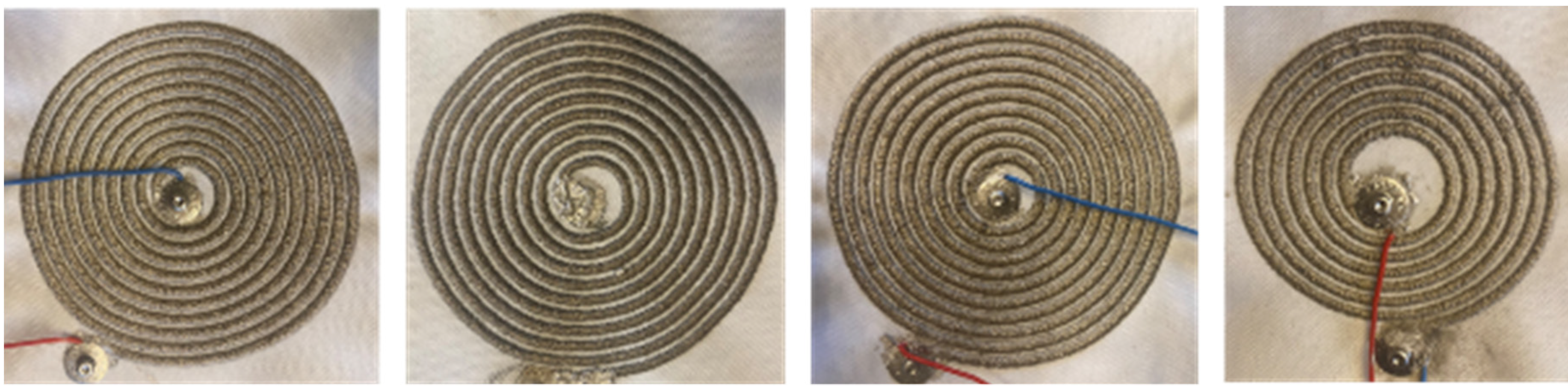
Tailored wire placement is used as a further embroidery method (test series S, Figure 2). A 100% polyester canvas fabric was used as the embroidery base. To prevent the stitches from sinking into the textile, an embroidery stabilizer was attached for the embroidery process. The individual windings cannot be placed arbitrarily close to each other due to the overstitch width, which means a possible loss factor for the power transmission. If the windings of the spiral coil are constructed too close to each other, the conductor may be punctured by a needle. This is also the reason why the TWP coils became slightly larger compared to the reference designs of the Qi coils.
The coils were stitched with an outer diameter of 40, 50, and 60 mm, with the three different conductor materials: ELITEX (E), wrapping yarn (U), and copper strand (L). The first two coils 60E12 and coil 60U12 had an outer diameter of 60 mm and an inner diameter of 11 mm. They each had 12 turns and a space of 1.5 mm between the turns. ELITEX and the wrapping yarn were used as conductor materials. The third stitched coil 60L12 had the same shape, size and number of turns as the previous coils, only the conductor material was replaced by the copper strand. Due to the larger wire diameter, the distance between turns was 0.5 mm and the inner diameter was 9 mm. An overview of the coils is shown in Table 3.
The coils: 50E15, 50U15, and 50L15 had an outer diameter of 50 mm (Figure 3). Coils 50E15 and 50U15 had an inner diameter of 15 mm and their turns had a distance of 0.5 mm to each other. Coil 50L15 had an inner diameter of 11 mm and there was no distance between the windings.
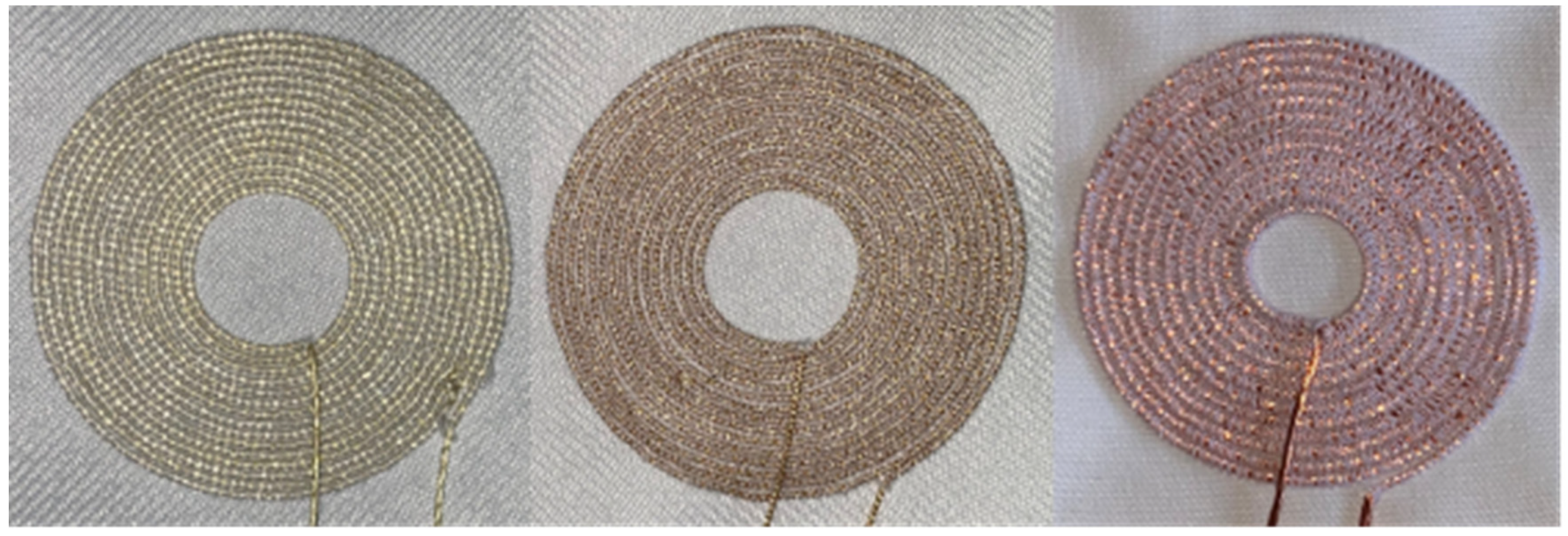
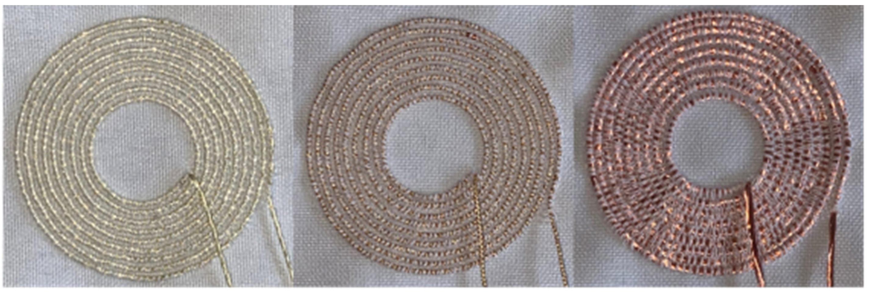
2.2.2. Wound Coils
The coils were wound by hand: test series W (Figure 5). ELITEX and the wrapping yarn were used as coil material. Compared to stitched coils, hand winding had the considerable advantage that any geometry could be implemented without causing significant size deviations. In this context, coil winding technology refers to the winding or forming of an electrical conductor into a coil form. The manufacturing process of coil winding is classified within the DIN 8580 standard [11].
The geometry of the wound coil WPR1 corresponds to the sample coil of the Qi standard power receiver. The coil WPR2 corresponds to Qi sample coil 2, the coil WPR3 corresponds to Qi sample coil 3, coil WPR4 corresponds to Qi sample coil 4, WPR5 corresponds to Qi sample coil 5 (Figure 5). The dimensions can be taken from Table 4.
2.2.3. Printed Coils
The stencil printing process is widely used in textile finishing. The print substrate is pressed through the screen-printing stencil with a rubber squeegee and applied directly to the textile. Before printing, the print design is affixed to the screen. During the printing process, the squeegee brings the print substrate through open screen areas on the print base. In order to achieve a higher application quantity and layer thickness, the squeegeeing process can also be repeated several times [12].
The first geometry D180 had an outer diameter of 80 mm and an inner diameter of 25 mm. The coil had 11 turns, whose track width was 1.5 mm. The distance between the turns was <1 mm. The second print pattern D280 had an outer diameter of 80 mm, an inner diameter of 23 mm and 7 windings. The track width was 3 mm per turn, but there was a deviation of ± 1 mm because the print quality was not constant. Coil D300 had a diameter of 100 mm outside and 30 mm inside. The coil had 7 turns with a track width of 3 mm per turn (Figure 6, Table 5).
2.3. Quality Evaluation of the Coils
In the following section, we will show a method to examine the previously presented textile coils for inductive energy transmission and we will evaluate the difference between the various types. Therefore, we use the coupling factor and the quality factor. The coupling factor merely describes which fraction of a generated magnetic field actually passes through a receiving coil. To obtain a high coupling factor, it would be useful, to couple two identically constructed coils.
In order to compare the transmission characteristics of the textile receiver coil, we use the transmission quality [13]. The transmission quality is a system parameter that can be determined metrologically and analytically and it enables an objective comparison of different systems. It indicates the efficiency which can be achieved under ideal conditions. It also provides information about the drop-in efficiency with variable load resistance. Transmission quality [13]
We can determine the maximum possible efficiency by using the transmission quality of the system
The maximum efficiency is plotted against the transmission quality in Figure 7.
The transmission quality was measured by using a two-port network [14]. Therefore, we developed the following equivalent circuit. The coupled coils are linear, time invariant and reciprocal systems, which can be represented in a T-equivalent circuit diagram diagram (Figure 8). The left side of the equivalent circuit (input) is described by the voltage V1 and the current I1. Similarly, voltage V2 and current I2 describe the output. All indicated voltages and currents are alternating quantities. The impedances Z11, Z22, and Z12 are required.
The impedance is the AC resistance consisting of an active component (ohmic resistance) and a reactive component (reactance). It establishes a relationship between voltage and current and their phase shift.
R represents the ohmic resistance and X represents the reactance, which is often frequency-dependent. For a coil, X with L as inductance is valid
In order to determine the impedances Z11, Z22, and Z12, they are divided into real and imaginary parts according to (4.7). The measurement system feeds the device with a known AC voltage and measures the current in magnitude and phase. Furthermore, the system offers the possibility to convert this result directly into an inductance as well as an ohmic loss resistance according to (4.8).
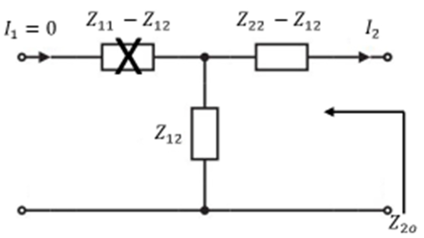
The first measurement corresponds to the impedance of the input, while the output is unloaded (Figure 9). This impedance is henceforth named Z1o. It corresponds to the impedance of the transmitting coil with a coupled receiving coil and open terminals. In this case, the impedance at the input is independent from the series impedance Z22 − Z12.
The procedure is reversed and the impedance at the output is measured with the input open during the second measurement (Figure 10). Z2o is determined analogously to Z1o.
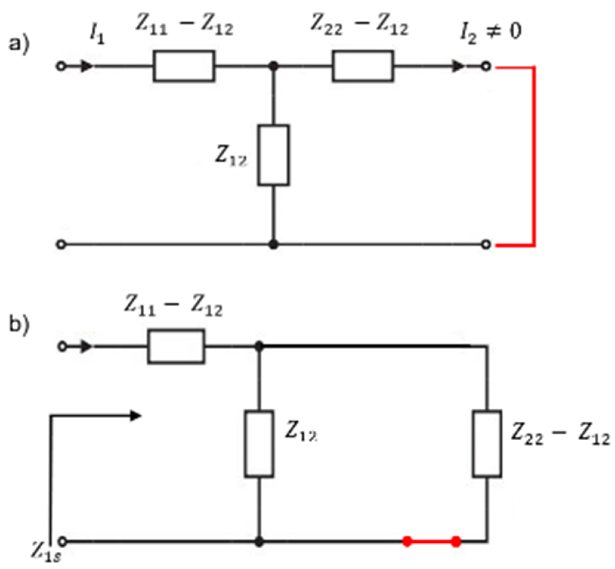
In the third measurement, the impedance at the input is measured again, but this time with a shorted output, which is shown in the following equivalent diagram.
Due to the reciprocity, the previously calculated result can be checked in a fourth measurement. For this purpose, the impedance of the output can be measured when the input is short-circuited.
In order to create a possibility for the qualification of a transmission system, the transmission quality was introduced [13]. It evaluates the qualities of the transmitter and receiver coil as well as the coupling. Thus, it provides a characteristic value for the suitability of energy transmission between the two coils.
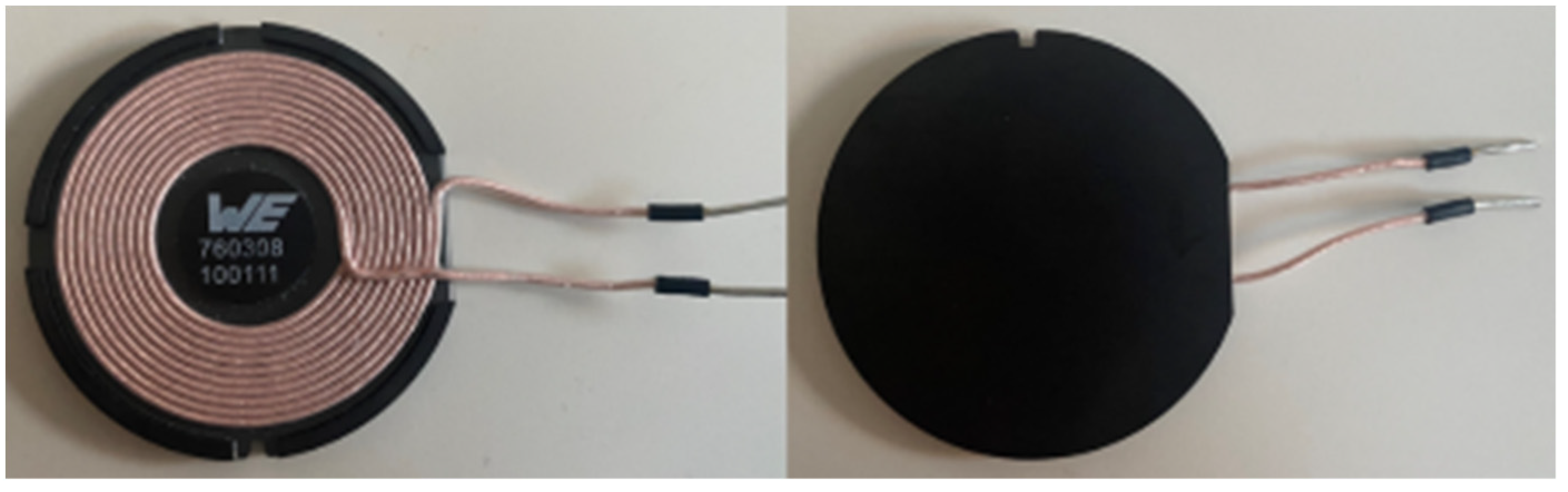
We used a transmitting coil from Würth Electronics (article number 760308100111, Figure 12). It had an outer diameter of 50 mm, was constructed according to reference transmitter design A10 [15] and consists of a ferrite and a copper strand. The inductance of the coil was 24 µH.
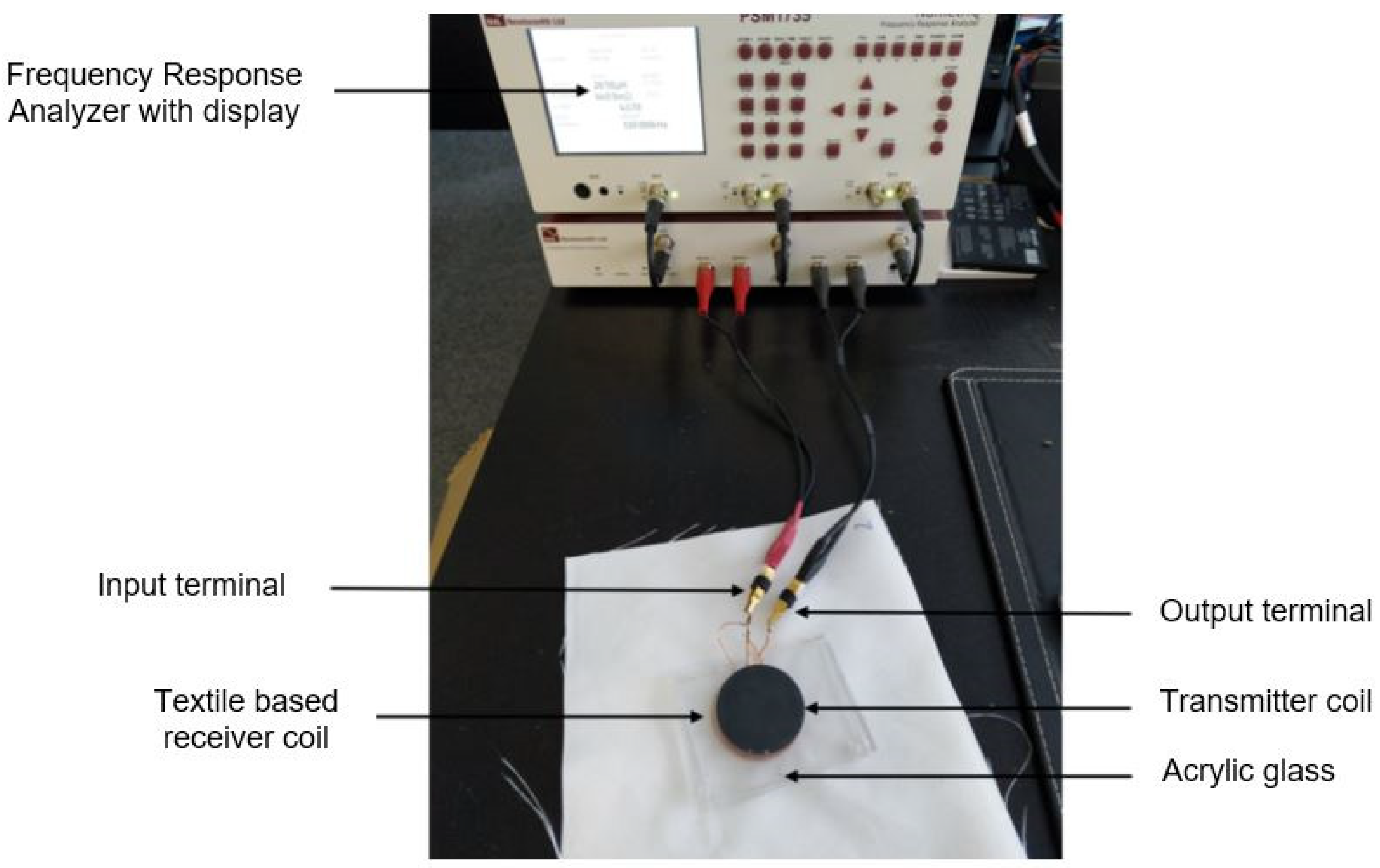
In the test series all textile receiver coils were successively coupled with this transmitter coil. Measurements were taken once with and once without ferrite foil on the back of the textile receiver coils. The influence of the ferrite foil on the transmission characteristics was determined. As already described, the measurements were carried out with a defined distance between the transmitting and receiving coils. A sheet of acrylic glass with a thickness of 3 mm was used for this purpose.
The measurements were performed with the PSM 1735 Frequency Response Analyzer from N4L (Figure 13). With the analyzer, we measured the resistance of the coils. The test frequency was defined with 110 kHz. The frequency is based on the frequency range of the Qi standard [15]. The frequency is used to regulate the power transmission. At low frequency, the greatest power is transmitted. Depending on their manufacturing process, the coils are assigned to a test series, this enables a clearer evaluation of the results. Test series D includes all printed coils, test series S the TWP coils, test series W contains the wound coils, and test series Z includes the stitched coils from Statex.
3. Results
Efficiency is the most important parameter for power transfer, as it is the ratio of output to input. The evaluation criteria are the transmission quality, as well as the maximum achievable efficiency of the test objects (Table 6). All values were measured three times and averaged.
The coils are subdivided according to their manufacturing method and the coil material. The results are listed in the following tables. Table 7 contains the calculated results for the transmission quality Qk and the maximum achievable efficiency η of the stitched coils from test series S, with and without the use of the ferrite foil. In the following, we present the results from coils, which show peculiarities for example by a very good or very bad result.
The 50E15 coil without ferrite has a transmission quality of 5.15 and a max. efficiency of 0.675. Considering the results of the measurements with ferrite, a significant increase of both parameters can be observed. The transmission quality can be increased to 8.02 and the max. efficiency up to 0.780, which means an increase of 10.5%. For the 40E9 coil, we observe a 14% improvement of the max. efficiency from 0.620 to 0.760. While the highest transmission quality of the ELITEX coils with ferrite is 8.02, with a max. efficiency of 0.780 (78%). The coil 50L15 already achieves a transmission quality of 35.5 without ferrite, which even increases to 49.45 with ferrite, which corresponds to a max. efficiency of 0.960 (96%). The other two coils made out of stranded copper wires, (60L12, 40L9) also have a high transmission quality of >40 and a max. efficiency greater than 0.90 with and without ferrite. Coil 60U12 achieves a max. efficiency of 0.76 (76%) and a transmission quality of 7.35. Coil 50U15 was not possible to connect to the measurement system.
Table 8 contains the results of the wound coils of ELITEX and wrapping yarn. Coil WPRE4 achieved a max. efficiency of 0.743 with a transmission quality of 6.81 without the use of the ferrite. In the measurements with ferrite, an increase in max. efficiency to 0.862 (86.2%) was achieved. Hence, this coil achieves the highest possible efficiency with a textile conductor material. This is probably due to the fact that the two inputs and outputs of the coil are connected in parallel, which halves the electrical resistance. WPRU4 achieves the second-highest results (7.01/0.75) with a fully textile structure.
The coil test conditions for the measurements from test series Z (embroidered coils with Shieldex yarns) were slightly different from the others. The test frequency was reduced to 100 kHz and we used a different ferrite foil. The transmission quality was still significantly below those of the other textile coils. Nevertheless, coil Z580 with ferrite foil could achieve the best test result with a transmission quality of 2.6499 and a max. efficiency of 0.452 (Table 9). The printed coils were also tested, but it was not possible to measure inductance. The capacitive component seemed to outweigh the inductive component.
4. Discussion
This paper deals with the development of textile induction coils for contactless energy transfer. For this purpose, three different methods for the possible fabrication of textile coils were investigated. Five varying coil materials were used for this project. The result of the manufacturing process resulted in total of 26 different coils, which differ in their shape and size, number of turns, and starting material. The different coils are critically examined on the base of their transmission properties. After an initial examination of all the results, it is already clear that the 60L12, 50L15, and 40L9 coils deliver significantly higher results. This is mainly due to the fact that the coils 60L12, 50L15, and 40L9 consist of stranded copper wire. These coils deliver the best transmission characteristics, even without ferrite.
Coil 50L15 achieves the best test results of the entire test (ηmax = 0.960). It is clear that textile conductors cannot compete with these electrical properties. Nevertheless, presentable results could be obtained even with the coils made entirely of textile fiber material. The wound WPRE4 coil from test series W achieved the best result of all textile coils with a maximum efficiency of 0.862 (86.2%). This unexpectedly positive result can be attributed to the high number of turns and the small distance between the turns. However, this result can also be significantly improved by using a ferromagnetic material.
The TWP coils became slightly larger compared to the reference designs of the Qi coils This does not mean that the TWP coils should be rated worse than smaller sized coils. Conversely, the size of the transmitting coil should be adjusted to achieve the best possible coupling between the two components.
A closer look at the individual results reveals that, among other things, there are differences between the various geometries. It turns out that the coils with a high number of turns and very small distance between the turns show the highest test results for the max. efficiency within their category (see 50E15, 50L15, WPRE4, WPRU4).
The results of coils made out of wrapping yarn bad regarding ηmax and Qk. Because of its much lower resistance, the fine copper wires around the yarn should result in better transmitting properties than a coated yarn. The wrapped yarns seem to occur eddy current which might negatively influence the magnetic field. Consequently, wrapped yarns are not the best solution for a final application. Furthermore, the contacting of the material is difficult.
The printed coils (test series D) did not provide values for inductances. Rather, capacitances were measured instead of inductances. This could be due to the fact that the inductance of the coils is very low and the capacitive component outweighs the inductive component. For this reason, no results are given for the printed coils. Under these conditions, a suitability of the printed coils cannot be verified. Therefore, we conclude printed coils we produced are not suitable for wireless energy transmission.
The printed coils from test series D, as well as the embroidered coils, proved poor or non-measurable transmission properties. An initial determination of the coil resistance already indicated a considerable low energy transmission. Another problem in the processing of Shieldex yarns is the absence of insulation. Since the windings are close together, it is indispensable to prevent short circuits. For this reason, we do not recommend coils with Shieldex yarns. However, it would be possible to improve the suitability for wireless transmission by increasing the degree of metallization as well as additional insulation. Due to the relatively high resistance, the yarn length should be reduced.
5. Conclusions
The value of the transmission quality is always based on ideal conditions at the input and output. The efficiency of a coil system depends on the power electronic which supplies electric current to the coil. In this paper, coil systems can only be qualitatively compared based on their transmission characteristics. We can compare the suitability of a coil system for energy transmission. The results have proven the possibility of contactless power transmission using various textile materials.
This paper shows and compares inductive energy transfer with textile receiver coils. The achievable transmission efficiencies are comparatively low. The samples show realization possibilities of textile coils, but they are not able to achieve the same results of a copper coil system in terms of efficiency. A lower efficiency can be accepted for low output powers, such as supplying some LEDs or a small sensor. Otherwise, the coils would probably heat up strongly and could cause burns to the user in the worst case. There are some difficulties in processing textile materials and in observing the electrical properties. For example, it is difficult to measure the electrical resistances of textile materials, because there is a lot of variation in the textile material. Selecting a suitable textile coil material, it should be decided whether the textile properties or the electrical properties are more important for the application. We recommend using insulated wires for inductive wireless power transmission. In either case, a ferrite foil should be used. Furthermore, not all coils had the same geometry. Further adjustments could be made in the measurement setup. That might have a positive effect on the transmission characteristics. In addition, the measurements could be carried out with a lateral offset in the x- and y-directions to determine how this affects the achievable efficiency and transmission quality. Before the textile coils can be integrated, further optimization is required. Follow-up investigations should be carried out for this purpose. In addition to the practical construction of actual transmission systems and the maximization of the actual overall efficiency, mechanical load and washability tests must be carried out.
In addition, a way to protect the receiving coil from moisture or dirt should be worked out. Electromagnetic compatibility poses a particular challenge, and it must be examined whether the transmission systems need special shielding.
For the transmission of larger amounts of energy we recommend using copper conductors. They show significantly higher efficiencies than textile conductive yarns, in any configuration. In addition, copper conductors are not significantly inferior to textile conductive yarns in terms of haptics and drapability. Textile conductive yarns can also be used as coil material, when transmitting small amounts of energy and focusing a purely textile setup.
Author Contributions
Conceptualization, S.M. and L.P.; Investigation, L.P.; Writing—original draft preparation, S.M.; Writing—review and editing, M.H.; Supervision G.T.G. All authors have read and agreed to the published version of the manuscript.
Funding
This research received no external funding.
Institutional Review Board Statement
Not applicable.
Informed Consent Statement
Not applicable.
Conflicts of Interest
The authors declare no conflict of interest.
References
- Ohnemus, J.; Rasel, D.F. FashionTech-Smart Textiles: Kurzexpertise im Auftrag des BMWi; ZEW Zentrum für europäische Wirtschaftsforschung: Mannheim, Germany, 2018. [Google Scholar]
- Brauner, P.; van Heek, J.; Schaar, A.K.; Ziefle, M.; Hamdan, N.A.H.; Ossmann, L.; Heller, F.; Borchers, J.; Scheulen, K.; Gries, T.; et al. Towards Accepted Smart Interactive Textiles. In Lecture Notes in Computer Science, Proceedings of the HCI in Business, Government and Organizations, Interacting with Information Systems: 4th International Conference, HCIBGO 2017, Vancouver, BC, Canada, 9–14 July 2017; Nah, F.F.-H., Tan, C.-H., Eds.; Springer: Berlin/Heidelberg, Germany, 2017; Volume 10293, pp. 279–298. [Google Scholar]
- van Heek, J.; Schaar, A.K.; Trevisan, B.; Bosowski, P.; Ziefle, M. User requirements for wearable smart textiles: Does the usage context matter (medical vs. sport)? In Proceedings of the 8th International Conference on Pervasive Computing Technologies for Healthcare, Oldenburg Germany, 20–23 May 2014. [Google Scholar]
- Schraven, S.; Kley, F.; Wietschel, M. Induktives Laden von Elektromobilen—Eine techno-ökonomische Bewertung. Z Energiewirtsch 2011, 35, 209–219. [Google Scholar] [CrossRef] [Green Version]
- Koo, H.R.; Lee, Y.J.; Gi, S.; Khang, S.; Lee, J.H.; Lee, J.H.; Lim, M.G.; Park, H.J.; Lee, J.W. The effect of textile-based inductive coil sensor positions for heart rate monitoring. J. Med. Syst. 2014, 38, 2. [Google Scholar] [CrossRef] [PubMed]
- Sun, D.; Chen, M.; Podilchak, S.; Georgiadis, A.; Abdullahi, Q.S.; Joshi, R.; Yasin, S.; Rooney, J.; Rooney, J. Investigating flexible textile-based coils for wireless charging wearable electronics. J. Ind. Text. 2020, 50, 333–345. [Google Scholar] [CrossRef]
- Li, Y.; Grabham, N.; Torah, R.; Tudor, J.; Beeby, S. Textile-Based Flexible Coils for Wireless Inductive Power Transmission. Appl. Sci. 2018, 8, 912. [Google Scholar] [CrossRef] [Green Version]
- Imbut, Spezialfäden—Imbut: Smart Textiles Solutions. Available online: https://www.imbut.de/de/spezialfaeden (accessed on 27 October 2020).
- ZSK Stickmaschinen GmbH, Tailored Wire & Tube Placement: Funktionalisierung von Textilen Materialien. Available online: https://www.zsk.de/de/branchenloesungen/technische-stickerei/tailored-wire.php (accessed on 24 July 2020).
- Block Transformatoren-Elektronik GmbH, CLI 200/30: Lackisolierte Kupferlitze CLI. Available online: https://www.block.eu/de_DE/produktvariante/cli-20030 (accessed on 7 November 2020).
- Hagedorn, J.; Blanc, F.S.-L.; Fleischer, J. Handbuch der Wickeltechnik für Hocheffiziente Spulen und Motoren: Ein Beitrag zur Energieeffizienz; Springer: Berlin/Heidelberg, Germany, 2016. [Google Scholar]
- Grabowski, B.; Fick, B. Drucktechniken: Das Handbuch zu allen Materialien und Methoden; DuMont: Köln, Germany, 2016. [Google Scholar]
- Huwig, D. Übertragungssysteme Vergleichen. Available online: https://www.etatronix.de/wp-content/uploads/2020/10/etatronix_EE_Kompendium_2014.pdf (accessed on 7 November 2020).
- Freitag, H. Einführung in die Zweitortheorie, 4th ed.; Vieweg+Teubner Verlag: Wiesbaden, Germany, 1984. [Google Scholar]
- Qi Wireless Power Transfer, The Qi Wireless Power Transfer System Power Class 0 Specification: Part 4: Reference Designs, Wireless Power Consortium, p. 54 ff. Available online: http://gbtp.or.kr/wireless_eng/upload//20171110025634271.pdf (accessed on 10 November 2020).
Figure 1.
Embroidered coils with Shieldex yarn (from left to right) Z175, Z275, Z375, Z455.

Figure 2.
Embroidered coils with a diameter of 60 mm (from left to right) 60E12 ELITEX, 60U12 wrapping yarn, 60L12 copper wire.
Figure 2.
Embroidered coils with a diameter of 60 mm (from left to right) 60E12 ELITEX, 60U12 wrapping yarn, 60L12 copper wire.

Figure 3.
Embroidered coils with a diameter of 50 mm (from left to right) 50E12 ELITEX, 50U12 wrapping yarn, 50L12 copper wire.
Figure 3.
Embroidered coils with a diameter of 50 mm (from left to right) 50E12 ELITEX, 50U12 wrapping yarn, 50L12 copper wire.

Figure 4.
Embroidered coils with a diameter of 40 mm (from left to right) 40E12 ELITEX, 40U12 wrapping yarn, 40L12 copper wire.
Figure 4.
Embroidered coils with a diameter of 40 mm (from left to right) 40E12 ELITEX, 40U12 wrapping yarn, 40L12 copper wire.

Figure 5.
Wound coils according to the Qi standard with ELITEX and wrapping yarn: WPR1E, WPR2E, WPR3E, WPR4E, WPR5E, (upper row from left to right) WPR1U, WPR2U, WPR3U, WPR4U, and WPR5U (bottom row from left to right).
Figure 5.
Wound coils according to the Qi standard with ELITEX and wrapping yarn: WPR1E, WPR2E, WPR3E, WPR4E, WPR5E, (upper row from left to right) WPR1U, WPR2U, WPR3U, WPR4U, and WPR5U (bottom row from left to right).

Figure 6.
Printed coils according to the Qi standard: Primer (left), printing stencil (middle) and printed coils (right).
Figure 6.
Printed coils according to the Qi standard: Primer (left), printing stencil (middle) and printed coils (right).

Figure 7.
Quality curve: efficiency vs. transmission.

Figure 8.
T-equivalent circuit diagram.

Figure 9.
First measurement.

Figure 10.
Second measurement.

Figure 11.
(a,b) shows the third measurement.

Figure 12.
Picture of the Transmitter coil 760308100111 from Würth Electronics for the test setup.

Figure 13.
Picture of the test setup.


Table 1.
Material data of the conductive wire/yarn.
| Material | Shieldex 117/17 dtex 2ply HC+B | Shieldex 235/36 dtex 2ply HC+B | ELITEX I PVC_B14/12_235/ f34x4_PA/AG | Wrapped Yarn | Lacquered Copper Strand CLI 200/30 |
| Raw material | polyamide 6.6 | polyamide 6.6 | polyamide | wrapped yarn | 100% copper |
| coating | 99% silver | 99% silver | >99% Silber | lacquered copper | polyurethane. |
| Yarn count | 295 dtex | 605 dtex | 0.236 mm2 | ||
| Electrical resistance | 80 Ω/m | <300 Ω/m | 5 Ω/m 0.5 A at 30 °C | 20 Ω/m | |
| Picture |  |  |  |  |  |
Table 2.
Overview of embroidered coils with Shieldex yarns—test series Z.
| Coil | Z175 | Z275 | Z375 | Z455 |
|---|---|---|---|---|
| Diameter | 75 | 75 | 75 | 55 |
| Windings | 10 | 10 | 10 | 7 |
| Yarn | Shieldex 235/ Shieldex 235 | Shieldex 117 | Shieldex 235 | Shieldex 235/ Shieldex 235 |
| Track width | 2 mm | 2 mm | 2 mm | 1.5 mm |
Table 3.
Different coil geometries–tailored wire placement.
| Outer Diameter (mm) | Inner Diameter (mm) | Windings | Material | |
|---|---|---|---|---|
| S60E12 | 60 | 11 | 12 | ELITEX |
| S60U12 | 60 | 11 | 12 | wrapping yarn |
| S60L12 | 60 | 9 | 12 | braid wire |
| S50E15 | 60 | 15 | 15 | ELITEX |
| S50U15 | 50 | 15 | 15 | wrapping yarn |
| S50L15 | 50 | 11 | 15 | braid wire |
| S40E9 | 40 | 15 | 9 | ELITEX |
| S40U9 | 40 | 15 | 9 | wrapping yarn |
| S40L9 | 40 | 12 | 9 | braid wire |
Table 4.
Structure of the wound coils according to Qi standard.
| WPR1 | WPR 2 | WPR3 | WPR4 | WPR5 | |
|---|---|---|---|---|---|
| Outer diameter | 44.25 × 32.25 mm | 32 mm | 47 mm | 47 mm | 40 mm |
| Inner diameter | 28.75 × 14.75 mm | 21.7 mm | 24.25 mm | 28 mm | 22 mm |
| Windings | 14 | 9 | 12 | 10 | 15 |
| Layers | 1 | 2 | 1 | 2 | 1 |
| Material | ELITEX/wrapping yarn | ELITEX/wrapping yarn | ELITEX/wrapping yarn | ELITEX/wrapping yarn | ELITEX/wrapping yarn |
Table 5.
Structure of the wound coils according to Qi standard.
| D180 | D280 | D300 | |
|---|---|---|---|
| Outer diameter | 80 mm | 80 mm | 100 mm |
| Inner diameter | 25 mm | 23 mm | 30 mm |
| Windings | 11 | 7 | 7 |
| Track width | 1.5 mm | 3 mm | 3 mm |
| Material | Silver printing paste | Silver printing paste | Silver printing paste |
Table 6.
Measurement results of the copper coils.
| Transmitter Coil | Receiver Coil | ||
|---|---|---|---|
| 760308100111 | 760308100111 | 93.84 | 0.9789 |
Table 7.
Results for transmission quality Qk and maximum efficiency ηmax of test series S.
| Name | ||||
|---|---|---|---|---|
| Without ferrite foil | With ferrite foil | |||
| 60E12 | 3.99 | 0.564 | 5.52 | 0.693 |
| 50E15 | 5.15 | 0.675 | 8.03 | 0.778 |
| 40E9 | 4.28 | 0.620 | 7.23 | 0.760 |
| 60U12 | 3.11 | 0.514 | 7.35 | 0.760 |
| 50U15 | No measurement possible | |||
| 40U9 | 2.93 | 0.490 | 5.41 | 0.688 |
| 60L12 | 25.02 | 0.923 | 41.44 | 0.950 |
| 50L15 | 35.5 | 0.945 | 49.45 | 0.960 |
| 40L9 | 29.7 | 0.935 | 42.15 | 0.954 |
Table 8.
Results for transmission quality Qk and maximum efficiency ηmax of test series W.
| Name | ||||
|---|---|---|---|---|
| Without ferrite foil | With ferrite foil | |||
| WPRE1 | 5.61 | 0.697 | 8.07 | 0.780 |
| WPRE2 | 5.09 | 0.670 | 5.68 | 0.701 |
| WPRE3 | 5.85 | 0.708 | 7.32 | 0.759 |
| WPRE4 | 6.81 | 0.743 | 10.51 | 0.862 |
| WPRE5 | 5.57 | 0.695 | 8.21 | 0.780 |
| WPRU1 | No measurement possible | |||
| WPRU2 | 2.92 | 0.490 | 4.10 | 0.608 |
| WPRU3 | 4.24 | 0.619 | 5.23 | 0.680 |
| WPRU4 | 5.17 | 0.676 | 7.01 | 0.750 |
| WPRU5 | 4.39 | 0.629 | 6.92 | 0.748 |
Table 9.
Results for transmission quality Qk and maximum efficiency ηmax of test series Z.
| Name | ||||
|---|---|---|---|---|
| Without ferrite foil | With ferrite foil | |||
| Z175 | 1.1255 | 0.0591 | 1.2511 | 0.1115 |
| Z275 | 1.0642 | 0.0311 | 1.1129 | 0.0534 |
| Z455 | 1.0801 | 0.0385 | 1.1279 | 0.0601 |
| Z580 | 1.0616 | 0.0299 | 2.6499 | 0.4520 |
Publisher’s Note: MDPI stays neutral with regard to jurisdictional claims in published maps and institutional affiliations. |
© 2021 by the authors. Licensee MDPI, Basel, Switzerland. This article is an open access article distributed under the terms and conditions of the Creative Commons Attribution (CC BY) license (https://creativecommons.org/licenses/by/4.0/).
Share and Cite
MDPI and ACS Style
Micus, S.; Padani, L.; Haupt, M.; Gresser, G.T. Textile-Based Coils for Inductive Wireless Power Transmission. Appl. Sci. 2021, 11, 4309. https://0-doi-org.brum.beds.ac.uk/10.3390/app11094309
AMA Style
Micus S, Padani L, Haupt M, Gresser GT. Textile-Based Coils for Inductive Wireless Power Transmission. Applied Sciences. 2021; 11(9):4309. https://0-doi-org.brum.beds.ac.uk/10.3390/app11094309
Chicago/Turabian StyleMicus, Sebastian, Laura Padani, Michael Haupt, and Götz T. Gresser. 2021. "Textile-Based Coils for Inductive Wireless Power Transmission" Applied Sciences 11, no. 9: 4309. https://0-doi-org.brum.beds.ac.uk/10.3390/app11094309
Note that from the first issue of 2016, this journal uses article numbers instead of page numbers. See further details here.