
Central Non-Linear Model-Based Predictive Vehicle Dynamics Control


Chair of Mechatronics, Faculty of Engineering, University of Duisburg-Essen, 47057 Duisburg, Germany
*
Author to whom correspondence should be addressed.
Appl. Sci. 2021, 11(10), 4687; https://0-doi-org.brum.beds.ac.uk/10.3390/app11104687
Submission received: 24 April 2021
/
Revised: 17 May 2021
/
Accepted: 17 May 2021
/
Published: 20 May 2021
(This article belongs to the Special Issue Performance and Safety Enhancement Strategies in Vehicle Dynamics and Ground Contact)
Abstract
:Featured Application
This contribution presents a central predictive control of the vehicle dynamics regarding the roll, self-steering and pitch behavior.
Abstract
Considering automated driving, vehicle dynamics control systems are also a crucial aspect. Vehicle dynamics control systems serve as an important influence factor on safety and ride comfort. By reducing the driver’s responsibility through partially or fully automated driving functions, the occupants’ perception of safety and ride comfort changes. Both aspects are focused even more and have to be enhanced. In general, research on vehicle dynamics control systems is a field that has already been well researched. With regard to the mentioned aspects, however, a central control structure features sufficient potential by exploiting synergies. Furthermore, a predictive mode of operation can contribute to achieve these objectives, since the vehicle can act in a predictive manner instead of merely reacting. Consequently, this contribution presents a central predictive control system by means of a non-linear model-based predictive control algorithm. In this context, roll, self-steering and pitch behavior are considered as control objectives. The active roll stabilization demonstrates an excellent control quality with a root mean squared error of rad averaged over both validation maneuvers. Compared to a vehicle utilizing a conventional control approach combined with a skyhook damping, pitching movements are reduced by %. Furthermore, an understeering behavior is maintained, which corresponds to the self-steering behavior of the passive vehicle. In general, the central predictive control, thus, increases both ride comfort and safety in a holistic way.
1. Introduction
Two major driving factors in vehicle development are increasing the safety and enhancing the ride comfort of the vehicle [1]. Especially in the context of automated driving, where the driver becomes a passenger, the perception of ride comfort changes significantly and at the same time gains in importance [2]. Moreover, a predictive mode of operation of the vehicle is beneficial. The implementation of a central predictive control of the vehicle dynamics addresses the objectives of increasing safety and ride comfort. The central control structure exploits synergies in terms of the control quality [3]. An overview of the state of the art for centralized integrated vehicle dynamics control systems is given in [4]. Furthermore, a predictive mode of operation allows the vehicle to act in a predictive way instead of just reacting [5]. In addition to classical approaches to control vehicle dynamics such as skyhook damping [6] and model-based control algorithms [7], the utilization of artificial intelligence is gaining increased attention. This mainly includes reinforcement learning [8], fuzzy inference systems [9] as well as deterministic artificial intelligence [10]. Due to the current regulation for the use of artificial intelligence in vehicles, a model-based approach is considered in this contribution.
For this purpose, a non-linear model-based predictive control algorithm implements the central predictive control. The control objectives pursued are an active roll stabilization, the manipulation of the self-steering behavior as well as the reduction of pitching movements. Mathematical models are used to predict the system behavior as a function of the manipulated variables [11]. Subsequently, the predicted system behavior is adapted to the desired system behavior in the form of reference trajectories. Furthermore, the manipulated variables can also be taken into account in the cost function to be minimized, so that the energy requirement within the central predictive vehicle dynamics control can likewise be reduced. A further advantage of the model-based predictive control is that it can also consider constraints on the manipulated variables. This enables actuator limits to be respected already during the optimization within the model-based predictive control algorithm [12]. As a result, this class of algorithms exhibits an excellent control quality. In [13], a model-based predictive control is used to stabilize a vehicle at its vehicle dynamics limits. Due to limitations of the side-slip angle and the yaw rate within the control algorithm the safety is enhanced. [14] apply a model-based predictive control algorithm to reduce vertical vehicle body motions. The vehicle is equipped with active suspension elements. Compared to a passive vehicle the ride comfort is significantly increased. A model-based predictive control algorithm is used in [15] to control the semi-active suspensions of a vehicle. This algorithm is validated against classical control approaches such as the skyhook damping presented in [16] and a clipped control strategy presented in [17]. For various road excitations, the model-based predictive control algorithm outperforms the classical control approaches.
This contribution is organized as follows: Section 2 presents the simulation framework, which is used to develop and validate the central predictive vehicle dynamics control. Section 3 introduces the central non-linear model-based predictive control algorithm with respect to the control objectives of roll, self-steering and pitch behavior. The central predictive control is then validated in Section 4. The contribution concludes in Section 5 with a summary as well as an outlook on future research tasks.
2. Simulation Framework
A simulation framework is used to implement the central predictive vehicle dynamics control and its validation. This framework is based on a co-simulation between IPG CarMaker and MATLAB & Simulink. Figure 1 illustrates the simulation framework. The multi-body simulation within the software IPG CarMaker is used for a realistic simulation of the vehicle. In addition to this realistic representation of the vehicle and the vehicle dynamics, IPG CarMaker also offers the possibility to edit and simulate the environment as well as driver models. In the context of the contribution, a vehicle of the sport utility vehicle class, a Lexus RX400h, is utilized. Due to the heightened center of gravity, this class of vehicle features higher tendencies towards movements in terms of rolling and pitching, which ultimately presents a more challenging task for the vehicle dynamics control. In order to accomplish the control and to achieve the control objectives, the vehicle is equipped with active stabilizers and semi-active dampers. The sensor equipment of the vehicle in IPG CarMaker is based on a minimalistic configuration. Available measured quantities are the longitudinal acceleration , the lateral acceleration , the yaw rate , the steering wheel angle , the velocity and the wheel speeds . Further fixed parameters of the vehicle are listed in Table 1.
The implementation of all algorithms is done in MATLAB & Simulink. In addition to the central predictive control, this also includes the generation of reference trajectories representing the control targets, the simulation of the actuators with regard to a realistic mapping, as well as the implementation of state estimators, which estimate the states necessary for the control not determined by sensors. Examples for the implementation of these state estimators are presented in [19,20,21].
In the following, the focus is on the central non-linear model-based predictive control algorithm.
3. Central Predictive Control
The steps of prediction and subsequent optimization characterize the central predictive control based on the non-linear model-based predictive control algorithm [22]. Within this contribution, the integrated model-based predictive control presented in [5] is extended and elaborated with respect to influencing the self-steering behavior. In this context, the control of roll behavior features the highest priority. Influencing the self-steering behavior and reducing pitching movements are subordinate control objectives.
3.1. Prediction
Theoretical modeling is used to generate the prediction models of the vehicle dynamics as a function of the manipulated variables. As a result, three interrelated prediction models are determined, which are presented individually. The split is made in relation to the control objectives of influencing the roll, the self-steering and the pitch behavior. In this context, and represent the manipulated variables of the counter roll torques at the front and rear axles, respectively. The variable is the damping factor of the semi-active damper at the front left, the damping factor of the semi-active damper at the front right, the damping factor of the semi-active damper at the rear left and the damping factor of the semi-active damper at the rear right.
3.1.1. Roll Behavior
To build the prediction model for the roll behavior, the vehicle body is cut free in the plane. Subsequently, the principle of angular momentum is set up around the vehicle’s roll center. The resulting equation can be transformed according to the roll acceleration at a certain time step :
Here, represents the moment of inertia about the -axis, the distance between the center of gravity and the roll center and the mass of the vehicle body. The external input variables are the lateral acceleration and the gravitational acceleration . In addition to the external input variables, the chassis elements also have an effect on the roll motion. Apart from the active stabilizers and the semi-active dampers, the vehicle is equipped with passive springs. These passive springs are characterized by the spring stiffnesses . Furthermore, and indicate the distances of the springs and dampers from the vehicle’s center plane. The index indicates which vehicle axle is concerned.
Using the scheme of the semi-implicit Euler method [23], the roll rate and the roll angle can be predicted as a function of the manipulated variables, starting from the roll acceleration :
Here, denotes the fixed step size.
3.1.2. Self-Steering Behavior
The basis for the prediction of the self-steering behavior is the single-track model [24]. Here, the wheels of an axle are virtually combined for modeling. The single-track model can be used to describe and predict the self-steering behavior and, thus, the response of the vehicle to steering movements [25]. Within the control system, the self-steering gradient is used as the characteristic variable:
The variables and are the slip angles at the front and rear axles, respectively. The slip angles are dependent of the yaw rate , the velocity and the side-slip angle . In addition, the steering angle affects the slip angle at the front axle . The parameters and represent the distance from the center of gravity to the front axle and the rear axle, respectively.
Whereas the steering angle and the velocity are kept constant within the prediction, the yaw rate and the side-slip angle are predicted. For this purpose, both Newton’s principle in the lateral direction and the principle of angular momentum in the plane are applied:
These two equations are solved for and , respectively. , , and represent the lateral forces at the tire front left, front right, rear left and rear right, respectively. The moment of inertia about the vertical axis is denoted as . By applying the scheme of the explicit Euler integration method [26], the time derivative of the side-slip angle and the yaw acceleration are then used to predict the side-slip angle and the yaw rate , respectively:
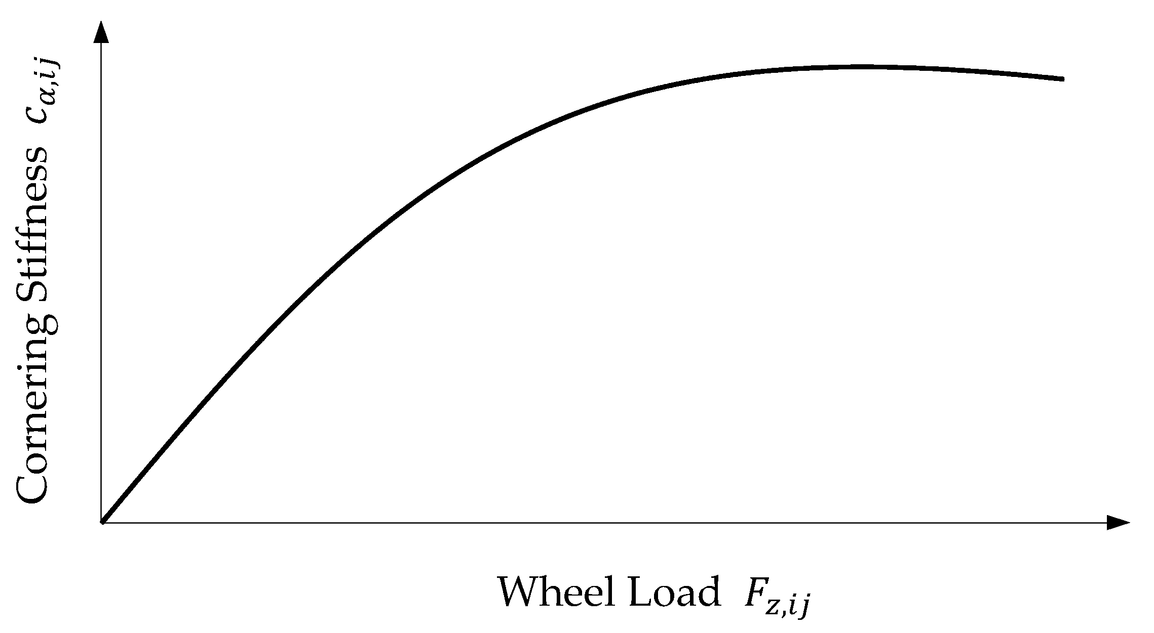
The influence of the chassis elements and, thus, the actuators on the self-steering behavior is exerted indirectly via the lateral tire forces . Here, the index denotes the vehicle side. The lateral tire forces correspond to the product of the slip angles and the respective cornering stiffnesses :
The cornering stiffness depends on the current wheel load . The dependency features a degressive characteristic. This characteristic is illustrated in Figure 2.
This relationship is modeled using a semi-empirical approach according to [27]. The degressive characteristic is described by a mathematical model, which is parameterized by empirical measurements:
The basis for the parameter identification is the tire model used in IPG CarMaker. This results in the parameters and of the semi-empirical tire model. Furthermore, is the nominal wheel load, which is present under static conditions. The influence of the actuators and, thus, of the control is taken into account via the wheel loads . The forces of the chassis elements are determined as a function of the roll behavior. The parameter indicates the distance of the stabilizer force application point from the vehicle’s center plane:
3.1.3. Pitch Behavior
In order to obtain the prediction model for the pitch behavior, the vehicle body is cut free in the plane. Subsequently, the principle of angular momentum is set up around the vehicle’s pitch center. The transformation of the resulting equation to the pitch acceleration yields:
denotes the moment of inertia about the lateral axis of the vehicle. The distance between the center of gravity and the pitch center is defined by . The parameters , and represent the distances between the center of gravity plane and the force application points of the springs, dampers and stabilizers, respectively. Based on the pitch acceleration at time , the pitch rate and the pitch angle for the time are likewise determined using the scheme of the semi-implicit Euler method:
This procedure likewise allows the pitch behavior to be predicted as a function of the manipulated variables.
3.2. Optimization
Following the prediction of the vehicle dynamics as a function of the manipulated variables, the optimization is executed with regard to the control objectives. The optimization is performed using the entire prediction horizon . The prediction horizon equals 0.15 s.
A major advantage of the non-linear model-based control algorithm is that constraints can be taken into account within the optimization. In this contribution, the manipulated variables are constrained. Thus, the physical limits of the actuators can be considered within the optimization. This results in the restriction of the counter roll torques and between a minimum counter roll torque and a maximum counter roll torque
as well as the restriction of the damping factors , , and in between a minimum damping factor and a maximum damping factor
For the description of the manipulated variables, temporal polynomials defined over the prediction horizon are used to take into account the temporal course within the optimization [5]. The definition of the polynomial degree is done with respect to the desired characteristics. The manipulated variables of the counter roll torques at the front and rear axle and , respectively, are defined as cubic polynomials:
The manipulated variables representing the damping factors , , and are specified by quadratic polynomials:
For the further description, the following notation is used:
The manipulated variables are grouped in the vector and the parameters of the polynomials are grouped in the vector . Furthermore, the predicted vehicle dynamic states of the roll angle , the pitch angle and the self-steering gradient are summarized in the vector :
The reference variables of the central predictive control are given in . These result from the generation of the reference trajectories:
A dynamic roll angle specification is used for the control objective of the active roll stabilization. A non-linear roll model with passive chassis elements is used for this purpose:
Here, represents the damping factors of the passive dampers. The passive stabilizers are characterized by the stiffnesses , the effective lengths and the lever arms . The double integration of the passive roll acceleration by the explicit Euler method yields the corresponding roll angle . This passive roll angle is then scaled by a scaling factor in order to determine the dynamic roll angle specification :
This dynamic reference roll angle specification improves comfort and safety overall, since the roll behavior is significantly reduced while still maintaining feedback of the lateral dynamics to the driver. For the pitch and self-steering behavior, static reference values are specified. The pitch angle specification corresponds to the stationary pitch angle of the vehicle. The specification of the self-steering gradient is used to achieve an understeering vehicle behavior corresponding to the passive vehicle behavior.
In addition to maintaining the reference trajectories, the optimization also takes into account the energy requirements of the actuators, which should be set to a minimum. For this reason, the weighting factors are introduced within the optimization. Thus, the focus can be set on the control quality as well as on the energy demand:
During the optimization, the cost function is minimized for the entire prediction horizon by adjusting the parameters of the polynomials . The optimization toolbox using the interior-point algorithm of MATLAB is used to solve the optimization [28,29]:
The result of the optimization is a set of optimal polynomial parameters over the entire prediction horizon, from which optimal manipulated variable trajectories are obtained. Finally, the principle of the receding horizon is applied [22]. Only the manipulated variables for the next time step are taken from the optimal manipulated variable trajectories and passed on to the actuator models. In the next time step, the entire process of prediction and optimization is repeated. This allows the non-linear model-based predictive control to adapt to non-modeled disturbances in an optimal way. Furthermore, the warm-start method is used [30], in which the last determined optimal polynomial parameters are used as a starting point for the optimization in the following time step. As a result, the number of iterations within the optimization can be reduced.
4. Results
In a first step, the validation maneuvers are presented which are used to validate the central predictive vehicle dynamics control. Subsequently, the focus is on the evaluation of the control quality for the individual driving maneuvers. The central predictive control is evaluated against a vehicle using a conventional roll control as well as a skyhook damping according to [16] and a vehicle with passive chassis elements. The conventional roll control is based on a proportional integral derivative controller, which is parameterized by using the control system design toolbox of MATLAB. The section concludes with a summary of the results obtained.
4.1. Validation Maneuvers
In order to validate the central non-linear model-based predictive control algorithm, two driving maneuvers are utilized. First, the double lane change driving maneuver is used [31]. For this purpose, the vehicle is first accelerated from standstill to the target velocity before performing the double lane change at constant velocity. The first lane change is performed counterclockwise. The target velocity within this contribution equals 50 km/h. The track limits for the double lane change are defined in the ISO standard. By combining the acceleration phase and the dynamic lane changes, the central predictive control can be validated with regard to all control objectives. The second driving maneuver for validation is a sinusoidal steering. This maneuver also involves accelerating the vehicle to a velocity of 50 km/h and then performing sinusoidal steering, according to [32]. Three periods with a steering wheel angle amplitude of 68° and a frequency of 1 Hz are performed. In addition, a significantly reduced friction coefficient of 0.4 is used for this driving maneuver.
4.2. Double Lane Change
The evaluation of the control quality for the double lane change is carried out separately for each control objective. The evaluation is done qualitatively and quantitatively.
4.2.1. Roll Behavior
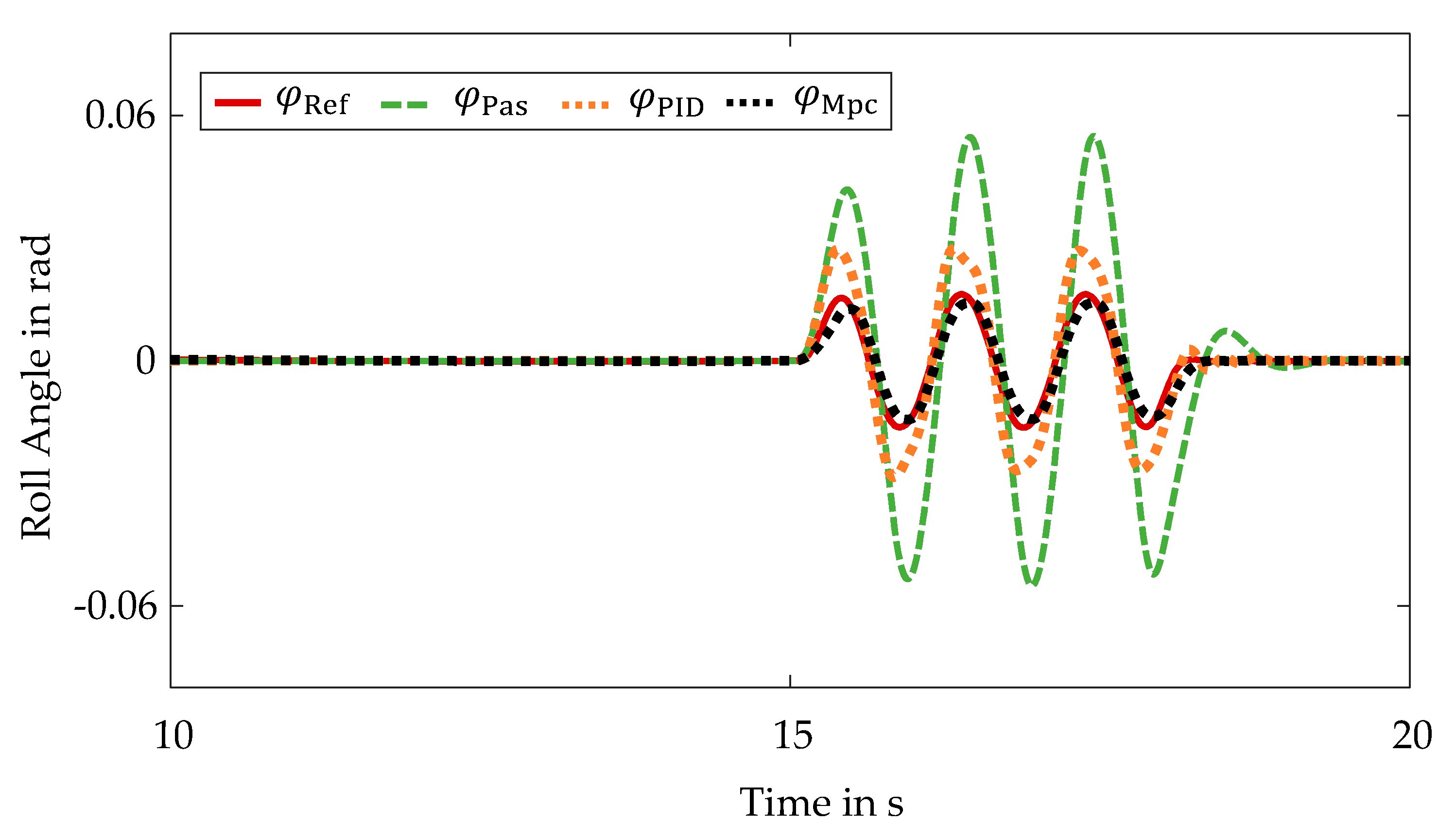
For the qualitative evaluation of the control quality of the non-linear model-based predictive control algorithm with respect to the main control objective, the roll angle is plotted over time for the validation maneuver. This is illustrated in Figure 3. The roll angle resulting from the execution of the non-linear model-based predictive control algorithm is represented by a dotted black line. The dynamic reference variable is represented by a red solid line. Furthermore, a green dashed line illustrates the roll angle curve of the vehicle with passive chassis elements and an orange dotted line illustrates the roll angle curve resulting from the conventional control approach.
The reference variable reduces the roll motion by about 75% compared to the passive vehicle . The roll angle resulting by the central predictive control follows the reference with an excellent accuracy. In contrast, the conventional control approach based on the proportional integral derivate controller and the skyhook damping results in increased control deviations. Thus, with the central predictive control, not only the safety but also the comfort is increased compared to the conventional control approach as well as to the passive vehicle behavior. The rolling movements that the passive vehicle exhibits during acceleration are not present for the vehicle utilizing the central predictive control and the vehicle utilizing the conventional control approach, respectively.
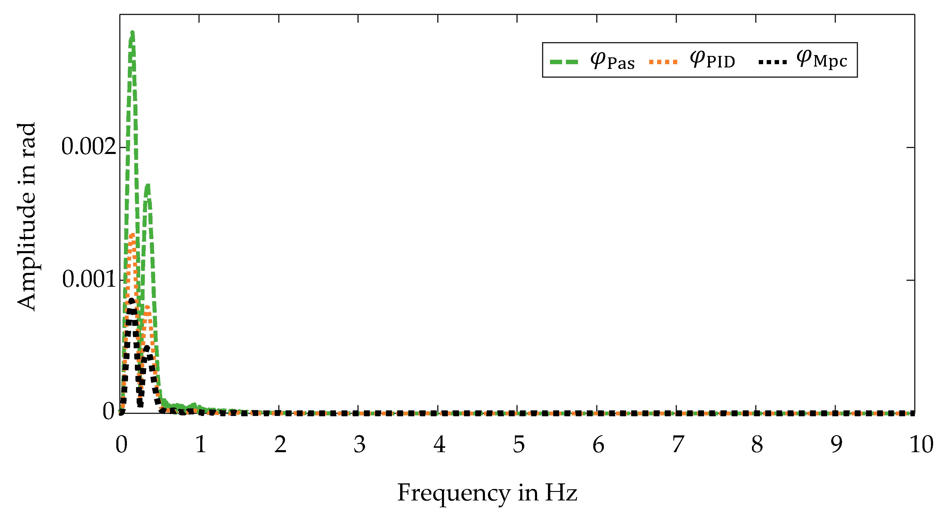
In addition, the impacts of the active roll stabilizations on the comfort are evaluated by examining the resulting frequency spectra. These are illustrated in Figure 4. Due to the use of the central predictive control, a stronger damping within the frequency spectrum is present compared to the passive vehicle. The frequency spectrum of the conventional approach also features a stronger damping than the passive vehicle. Compared to the central predictive control algorithm, however, a weaker damping is present.
Furthermore, the root mean squared errors are determined for the quantitative evaluation:
In relation to the active roll stabilization, the non-linear model-based predictive control exhibits a root mean squared error of rad. This corresponds to °. In contrast, the conventional control approach results in a root mean squared error of rad, which is equivalent to °. The quantitative evaluation, thus, confirms the qualitative analysis. The control quality of the central predictive control is excellent. In general, the central predictive control, thus, outperforms the conventional control approach.
4.2.2. Self-Steering Behavior
In comparison to controlling the roll angle, influencing the self-steering behavior is a subordinate control objective. Here, a constant understeering behavior is pursued, which corresponds approximately to the one of passive vehicle. Because the vehicle is equipped with active stabilizers and semi-active dampers, this control objective can only be pursued to a limited extent. With regard to the representability for the evaluation, the pseudo quantity is introduced:
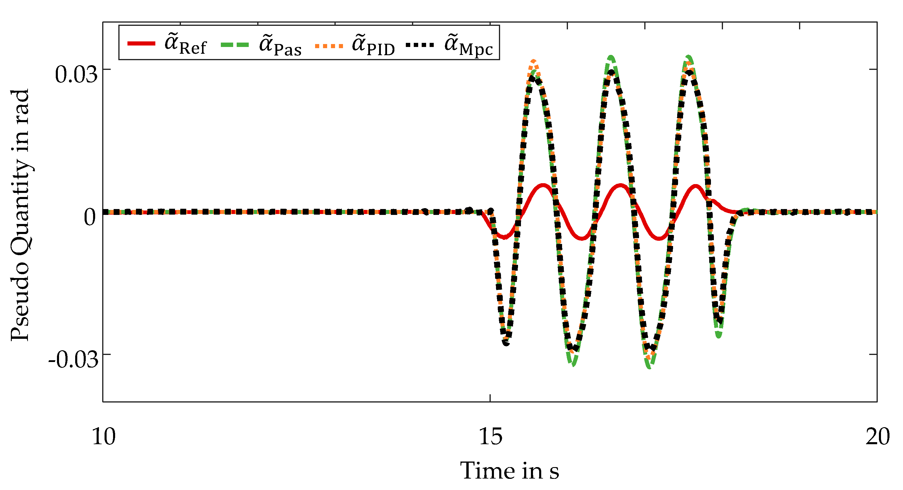
The pseudo quantity represents the difference between the slip angle of the front axle and rear axle and, thus, corresponds to the product of the self-steering gradient and the lateral acceleration . The evaluation is conducted in the following based on the pseudo quantity . The qualitative evaluation is performed using the pseudo quantity courses for the validation maneuver. This is shown in Figure 5.
With regard to the absence of lateral dynamics in the acceleration phase, only the section of the double lane change is considered. The representation of the pseudo quantity suggests a dynamic reference variable . However, this results from the dynamics of the lateral acceleration . With regard to safety, a constant self-steering gradient is used. The representation remains consistent with the evaluation of the roll behavior. The vehicle with the central predictive control shows an almost identical course of the pseudo quantity to the passive vehicle. Due to the weighting of this control target and the limited possibility to manipulate, there is a deviation from the reference variable. Since the conventional control approach does not explicitly consider the influence on the self-steering behavior, only a limited evaluation can be performed. For the validation maneuver of the double lane change, the conventional control exhibits a self-steering behavior corresponding to the passive self-steering behavior, similar to the central predictive control.
In principle, the control objective is satisfied by the central predictive control, since the self-steering behavior corresponds to the behavior of the passive vehicle despite utilizing an active control system. This is confirmed by examining the frequency spectra, which are illustrated in Figure 6.
The frequency spectrum for the vehicle with the central predictive control is almost identical to that of the passive vehicle. The conventional control approach features a similar frequency spectrum.
The quantitative evaluation for the whole validation maneuver results in a root mean squared error for the central predictive control of rad, which is equivalent to °. The conventional control approach yields a root mean squared error of rad, which corresponds to °.
4.2.3. Pitch Behavior
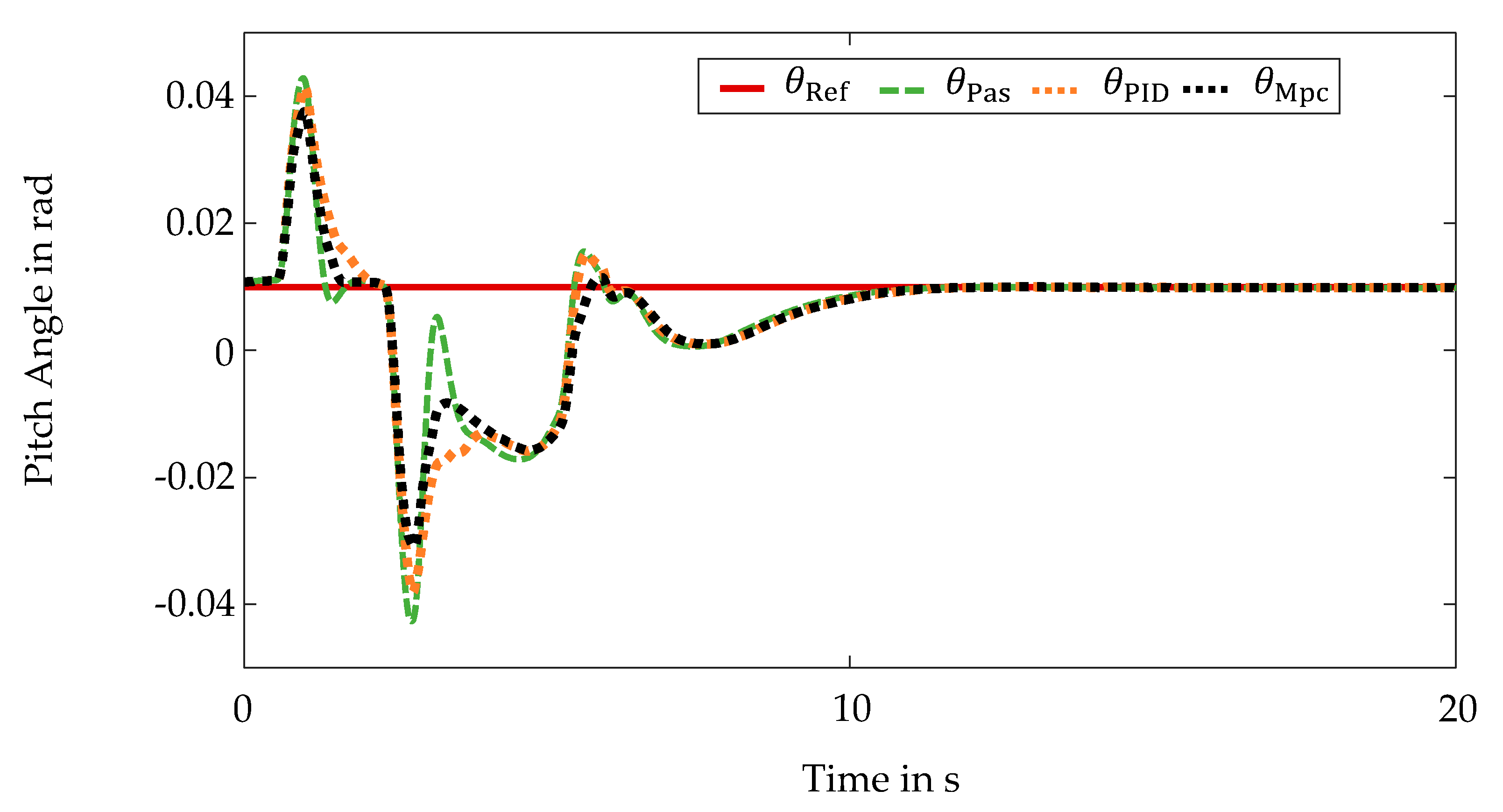
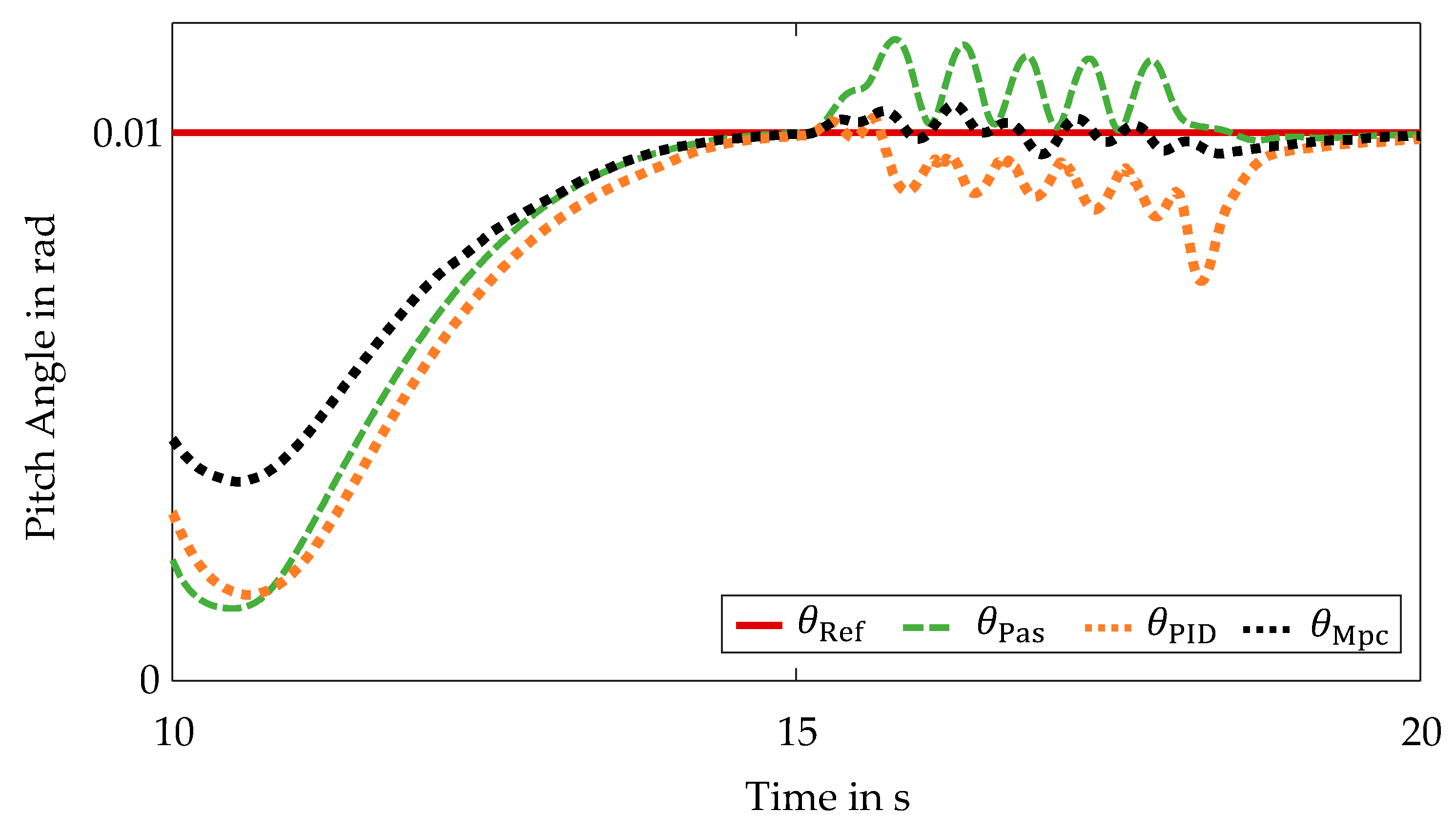
Similar to the manipulation of the self-steering behavior, the reduction of pitching movements is a subordinate control objective within the non-linear model-based predictive control algorithm. Due to the vehicle’s equipment with active stabilizers and semi-active dampers, only a limited influence on the pitch behavior is possible. In order to evaluate the central predictive control in a qualitative way with respect to the control objective of reducing the pitching movements, the pitch angle is plotted over time. The pitch angle curves are shown in Figure 7.
The focus is on the acceleration phase of the validation maneuver, since pitching movements are present here due to the gear changes and the present longitudinal accelerations. The pitching movements during the double lane change in contrast are negligibly small. The representation remains consistent. Analogous to the manipulation of the self-steering behavior, a constant reference variable is used. This reference variable represents the stationary pitch angle of the vehicle, which corresponds to the pitch angle that is present when the vehicle is at standstill. The reference variable cannot be adjusted fully by the present vehicle setup, but it is considered in order to implement the reduction of pitching movements. In comparison to the vehicle with passive chassis elements , pitching movements of the vehicle with the central predictive control are, therefore, reduced. The implementation of the skyhook damping within the conventional control approach also reduces pitching movements compared to the passive vehicle. By exploiting synergies, however, the implementation of the central predictive control results in a greater reduction of pitching movements compared to the conventional control approach.
The corresponding frequency spectra are shown in Figure 8. Here, the positive influence of the central predictive control is also evident. The non-linear model-based predictive control results in greater damping within the frequency spectrum. The amplitudes of the conventional control approach present at very low frequencies are sometimes even greater than those of the passive vehicle. In terms of ride comfort, the central predictive control, thus, provides a significant improvement in comparison to the application of the conventional control approach.
The quantitative evaluation confirms this statement. The non-linear model-based predictive control yields a root mean squared error of rad, which corresponds to °. The conventional control approach results in a root mean squared error of rad corresponding to °. By using the central predictive control, pitching movements are, thus, reduced compared to the conventional control approach as well as compared to the passive vehicle. As a result, the ride comfort is, thus, increased.
4.3. Sinusoidal Steering
The evaluation of the control quality for the sinusoidal steering maneuver is likewise performed qualitatively and quantitatively. The acceleration phase, which is already examined in Section 4.2, is neglected and only the sinusoidal steering phase is considered.
4.3.1. Roll Behavior
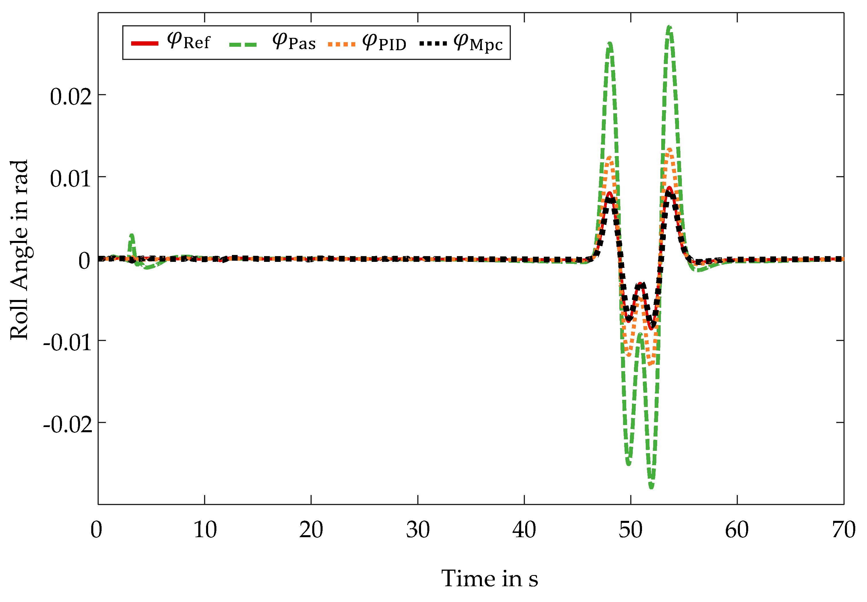
To evaluate the control quality of the central predictive control with a focus on the active roll stabilization, the roll angle curves during the sinusoidal steering are plotted. The present roll angle curves are shown in Figure 9.
As with the double lane change maneuver, the reference variable reduces the rolling motions by approximately 75% compared to rolling motions of the passive vehicle. The central predictive control is able to follow the reference variable despite the minimal friction coefficient. Compared to the results for the validation maneuver of the double lane change, there are slightly larger control deviations due to this low friction coefficient. In comparison to the conventional control approach, the centralized predictive control nevertheless features an improved control quality.
This is confirmed by the evaluation of the root mean squared errors. The non-linear model-based predictive control yields a root mean squared error of rad for the sinusoidal steering, which is equivalent to °. In contrast, the conventional control approach results in a root mean squared error of rad, which corresponds to °. Despite the aggravated road conditions, the control quality of the central predictive control is excellent.
4.3.2. Self-Steering Behavior
For the evaluation of the control quality with respect to the self-steering behavior, the courses of the pseudo quantity are first considered again. The resulting curves are illustrated in Figure 10.
Comparable to the results for the double lane change, the self-steering behavior implemented by the central predictive control system almost corresponds to the passive self-steering behavior . With regard to the reference variable , there are larger deviations due to the very low friction coefficient. Through the limited adjustment possibilities caused by the vehicle equipment and the prioritization of the control objectives, only a limited improvement of the control quality is achieved by the central predictive control compared to the passive vehicle. A similar self-steering behavior is obtained by the conventional control approach, though slightly larger deviations from the reference variable are present.
The non-linear model-based predictive control algorithm results in a root mean squared error of rad corresponding to °. The conventional control approach yields a root mean squared error of rad, which is equivalent to °.
In general, the control objective of influencing the self-steering behavior is achieved as well. A self-steering behavior corresponding to the passive self-steering behavior is present despite the application of the central predictive control system.
4.3.3. Pitch Behavior
The qualitative evaluation for the control objective of reducing pitching movements is likewise realized by examining the pitch angle curves during the sinusoidal steering. The pitch angle curves are shown in Figure 11.
The positive influence of central predictive control is likewise evident during the sinusoidal steering. Compared to the passive vehicle and the conventional control approach, the pitching movements are reduced.
The quantitative evaluation confirms these results. Whereas the vehicle utilizing the conventional control approach deviates from the stationary pitch angle by a root mean squared error of rad, which corresponds to °, the non-linear model-based predictive control results in a root mean squared error of rad, which corresponds to °.
In comparison to the passive vehicle and the application of the conventional control approach, the utilization of the central predictive control system, thus, increases the ride comfort.
4.4. Conclusions
The central predictive vehicle dynamics control fulfills the defined control objectives as desired. A summary of the control quality is given in Table 2. In addition to this, the results are compared with those of a vehicle with passive chassis elements and those obtained by a conventional control approach.
The main control objective of the central predictive vehicle dynamics control, the active roll stabilization, is met with an excellent control quality. In comparison to the conventional control approach, the control quality is improved by approximately %. Likewise, good results are achieved with regard to the further subordinate control objectives. As a result, pitching movements are reduced by approximately % compared to the conventional control approach. Despite the intervention of the control system, the self-steering behavior of the controlled vehicle corresponds to that of the passive vehicle.
The validation demonstrates the advantages of a centralized predictive control structure over a passive vehicle and a vehicle using a conventional control approach comprising a proportional integral derivative controller and a skyhook damping. The improvements in the control quality by of a non-linear model-based predictive control compared to a linear control approach utilizing a skyhook damping for a pure active roll stabilization are also presented in [33].
5. Conclusions and Outlook
This contribution presents a central predictive vehicle dynamics control system. The control objectives of an active roll stabilization, a manipulation of the self-steering behavior as well as a reduction of pitching movements are pursued. The control system is implemented by a non-linear model-based predictive control algorithm. The simulation framework comprising a co-simulation between IPG CarMaker and MATLAB & Simulink is used. The test vehicle utilized is a sport utility vehicle equipped with active stabilizers and semi-active dampers to realize the control. Due to the heightened center of gravity, the sport utility vehicle features an increased challenge in influencing rolling and pitching motions. Here, the implementation of active roll stabilization is the primary control objective. The weighting of the control objectives is done via corresponding weighting factors within the optimization of the non-linear model-based predictive control algorithm. The validation is performed for the driving maneuvers of the double lane change and the sinusoidal steering. In conclusion, the implementation of the central predictive control demonstrates an excellent control quality. The central predictive control increases safety and comfort significantly compared to a vehicle with passive chassis elements and a vehicle utilizing a conventional control approach.
The focus of this contribution is on the presentation of the central predictive vehicle dynamics control based on the non-linear model-based predictive control algorithm and the resulting excellent control quality. However, due to the numerical solution of the optimization problem, an increased computational effort is imposed at the same time. With regard to a future implementation of the central predictive control, a real-time implementation of this central predictive vehicle dynamics control with a reduced computational effort is required. Whereas classical approaches linearize the underlying prediction models and, thus, simplify them, making them analytically solvable, or limit the iteration steps of the optimization, future work will explore the use of artificial intelligence. Initial conceptual research has already shown a particular suitability of neuro-fuzzy inference systems to address and solve this issue [18].
Author Contributions
P.M.S.: conceptualization, methodology, software, validation, formal analysis, investigation, writing and editing, visualization. D.S.: supervision; project administration and critical revision. All authors have read and agreed to the published version of the manuscript.
Funding
This research received no external funding.
Institutional Review Board Statement
Not applicable.
Informed Consent Statement
Not applicable.
Acknowledgments
We acknowledge support by the Open Access Publication Fund of the University of Duisburg-Essen.
Conflicts of Interest
The authors declare no conflict of interest.
References
- Johansson, R. Vision Zero—Implementing a policy for traffic safety. Safety Sci. 2009, 47, 826–831. [Google Scholar] [CrossRef]
- Elbanhawi, M.; Simic, M.; Jazar, R. In the Passenger Seat: Investigating Ride Comfort Measures in Autonomous Cars. IEEE Intell. Transp. Syst. Mag. 2015, 7, 4–17. [Google Scholar] [CrossRef]
- Chen, W.; Xiao, H.; Wang, Q.; Zhao, L.; Zhu, M. Integrated Vehicle Dynamics and Control; John Wiley & Sons Singapore Pte. Ltd.: Singapore, 2016. [Google Scholar]
- Fan, Y.; Dao-Fei, L.; Crolla, D.A. Integrated Vehicle Dynamics Control—State-of-the art review. In Proceedings of the 2008 IEEE Vehicle Power and Propulsion Conference, Harbin, China, 3–5 September 2008; pp. 1–6. [Google Scholar]
- Sieberg, P.M.; Blume, S.; Reicherts, S.; Schramm, D. Nichtlineare modellbasierte prädiktive Regelung der Fahrzeugdynamik in Bezug auf eine aktive Wankstabilisierung und eine Nickreduzierung. In Forschung im Ingenieurwesen; Springer: Berlin/Heidelberg, Germany, 2019; Volume 83, pp. 119–127. [Google Scholar]
- Ikenaga, S.; Lewis, F.L.; Campos, J.; Davis, L. Active suspension control of ground vehicle based on a full-vehicle model. In Proceedings of the 2000 American Control Conference, ACC (IEEE Cat. No.00CH36334), Chicago, IL, USA, 28–30 June 2000; Volume 4016, pp. 4019–4024. [Google Scholar]
- Chang, S.; Gordon, T.J. A flexible hierarchical model-based control methodology for vehicle active safety systems. Veh. Syst. Dyn. 2008, 46, 63–75. [Google Scholar] [CrossRef] [Green Version]
- Bahr, M.; Reicherts, S.; Sieberg, P.; Morss, L.; Schramm, D. Application of Artificial Neural Networks for Active Roll Control Based on Actor-Critic Reinforcement Learning. In Proceedings of the Simulation and Modeling Methodologies, Technologies and Applications, Prague, Czech Republic, 29–31 July 2021; pp. 61–82. [Google Scholar]
- Li, H.-m.; Wang, X.-b.; Song, S.-B.; Li, H. Vehicle Control Strategies Analysis Based on PID and Fuzzy Logic Control. Procedia Eng. 2016, 137, 234–243. [Google Scholar] [CrossRef] [Green Version]
- Sands, T. Development of Deterministic Artificial Intelligence for Unmanned Underwater Vehicles (UUV). J. Mar. Sci. Eng. 2020, 8, 578. [Google Scholar] [CrossRef]
- Camacho, E.F.; Bordons, C.A. Model Predictive Control; Springer: Berlin, Germany, 1998. [Google Scholar]
- Grüne, L.; Pannek, J. Nonlinear Model Predictive Control. In Nonlinear Model Predictive Control: Theory and Algorithms; Grüne, L., Pannek, J., Eds.; Springer: Cham, Switzerland, 2017; pp. 45–69. [Google Scholar] [CrossRef]
- Beal, C.E.; Gerdes, J.C. Predictive control of vehicle roll dynamics with rear wheel steering. In Proceedings of the 2010 American Control Conference, Baltimore, MD, USA, 30 June–2 July 2010; pp. 1489–1494. [Google Scholar]
- Mehra, R.K.; Amin, J.N.; Hedrick, K.J.; Osorio, C.; Gopalasamy, S. Active suspension using preview information and model predictive control. In Proceedings of the 1997 IEEE International Conference on Control Applications, Hartford, CT, USA, 5–7 October 1997; pp. 860–865. [Google Scholar]
- Canale, M.; Milanese, M.; Novara, C. Semi-Active Suspension Control Using “Fast” Model-Predictive Techniques. IEEE Trans. Control Syst. Technol. 2006, 14, 1034–1046. [Google Scholar] [CrossRef] [Green Version]
- Hrovat, D. Survey of Advanced Suspension Developments and Related Optimal Control Applications. Automatica 1997, 33, 1781–1817. [Google Scholar] [CrossRef]
- Giua, A.; Seatzu, C.; Usai, G. Semiactive Suspension Design with an Optimal Gain Switching Target. Veh. Syst. Dyn. 1999, 31, 213–232. [Google Scholar] [CrossRef]
- Sieberg, P.M.; Hürten, C.; Schramm, D. Representation of an Integrated Non-Linear Model-Based Predictive Vehicle Dynamics Control System by a Co-Active Neuro-Fuzzy Inference System. In Proceedings of the 2020 IEEE Intelligent Vehicles Symposium (IV), Las Vegas, NV, USA, 19 October–13 November 2020; pp. 572–577. [Google Scholar]
- Sieberg, P.M.; Blume, S.; Reicherts, S.; Maas, N.; Schramm, D. Hybrid State Estimation—A Contribution towards Reliability Enhancement of Artificial Neural Network Estimators. IEEE Trans. Intell. Transp. Syst. 2021. [Google Scholar] [CrossRef]
- Sieberg, P.M.; Blume, S.; Schramm, D. Side-Slip Angle Estimation by Artificial Neural Networks for Vehicle Dynamics Control Applications. In Proceedings of the AmE 2021—Automotive meets Electronics 12th GMM-Symposium, Online, 10–11 March 2021. [Google Scholar]
- Blume, S.; Sieberg, P.M.; Maas, N.; Schramm, D. Neural Roll Angle Estimation in a Model Predictive Control System. In Proceedings of the IEEE Intelligent Transportation Systems Conference (ITSC)/ITSC 2019, Auckland, New Zealand, 27–30 October 2019; pp. 1625–1630. [Google Scholar]
- Rossiter, J.A. Model-Based Predictive Control—A Practical Approach; CRC Press: Boca Raton, FL, USA, 2004; p. 344. [Google Scholar]
- Cromer, A. Stable solutions using the Euler approximation. Am. J. Phys. 1981, 49, 455–459. [Google Scholar] [CrossRef]
- Schramm, D.; Hesse, B.; Maas, N.; Unterreiner, M. Vehicle Technology—Technical Foundations of Current and Future Motor Vehicles; De Gruyter Oldenbourg: Berlin, Germay; Boston, MA, USA, 2020. [Google Scholar] [CrossRef]
- Schramm, D.; Hiller, M.; Bardini, R. Vehicle Dynamics: Modeling and Simulation, 2nd ed.; Springer: Berlin/Heidelberg, Germany, 2018. [Google Scholar] [CrossRef]
- Butcher, J.C. Numerical Methods for Ordinary Differential Equations, 3rd ed.; John Wiley & Sons, Ltd.: Hoboken, NJ, USA, 2016. [Google Scholar] [CrossRef]
- Pacejka, H.B. Tyre and Vehicle Dynamics, 2nd ed.; Butterworth-Heinemann: Oxford, UK, 2006; p. 1. [Google Scholar]
- Waltz, R.A.; Morales, J.L.; Nocedal, J.; Orban, D. An interior algorithm for nonlinear optimization that combines line search and trust region steps. Math. Program. 2006, 107, 391–408. [Google Scholar] [CrossRef]
- Ypma, T.J. Historical Development of the Newton-Raphson Method. SIAM Rev. 1995, 37, 531–551. [Google Scholar] [CrossRef] [Green Version]
- Yildirim, E.A.; Wright, S.J. Warm-Start Strategies in Interior-Point Methods for Linear Programming. SIAM J. Optim. 2002, 12, 782–810. [Google Scholar] [CrossRef]
- ISO. ISO 3888-1:2018 Passenger Cars—Test Track for a Severe Lane-Change Manoeuvre—Part 1: Double Lane-Change; International Organisation for Standardization (ISO): Geneva, Switzerland, 2018. [Google Scholar]
- ISO. ISO 13674-1:2010 Road Vehicles—Test Method for the Quantification of on-Centre Handling—Part 1: Weave Test; International Organisation for Standardization (ISO): Geneva, Switzerland, 2010. [Google Scholar]
- Sieberg, P.M.; Reicherts, S.; Schramm, D. Nichtlineare modellbasierte prädiktive Regelung zur aktiven Wankstabilisierung von Personenkraftwagen. In Proceedings of the Vierte IFToMM D-A-CH Konferenz 2018, Lausanne, Switzerland, 15–16 February 2018; pp. 1–8. [Google Scholar]
Figure 1.
Simulation Framework, © 2021 IEEE. Reprinted, with permission, from [18].
Figure 1.
Simulation Framework, © 2021 IEEE. Reprinted, with permission, from [18].

Figure 2.
Degressive Characteristic of the Cornering Stiffness Regarding the Wheel Load.

Figure 3.
Control Quality Double Lane Change–Roll Behavior–Roll Angle Curves.

Figure 4.
Control Quality Double Lance Change-Roll Behavior-Frequency Spectra.

Figure 5.
Control Quality Double Lane Change–Self-Steering Behavior–Pseudo Quantity Curves.

Figure 6.
Control Quality Double Lane Change–Self-Steering Behavior–Frequency Spectra.

Figure 7.
Control Quality Double Lane Change–Pitch Behavior–Pitch Angle Curves.

Figure 8.
Control Quality Double Lane Change–Pitch Behavior-Frequency Spectra.

Figure 9.
Control Quality Sinusoidal Steering–Roll Behavior–Roll Angle Curves.

Figure 10.
Control Quality Sinusoidal Steering–Self-Steering Behavior–Pseudo Quantity Curves.

Figure 11.
Control Quality Sinusoidal Steering–Pitch Behavior–Pitch Angle Curves.


Table 1.
Vehicle Parameters.
| Parameter | Value | Unit |
|---|---|---|
| Vehicle Body Mass | 1820 | kg |
| Track Width | 1.538 | m |
| Wheelbase | 2.75 | m |
| Tires | 235/55R18 | - |
| Distance of the Center of Gravity to the Front Axle | 1.343 | m |
| Distance of the Center of Gravity to the Rear Axle | 1.407 | m |
| Height of the Center of Gravity | 0.682 | m |
| Height of the Center of Pitching | 0.3257 | m |
| Height of the Center of Rolling | 0.2826 | m |
| Moment of Inertia about the Lateral Axis | 2654 | kg m2 |
| Moment of Inertia about the Longitudinal Axis | 760 | kg m2 |
| Moment of Inertia about the Vertical Axis | 2774 | kg m2 |
Table 2.
Central Predictive Vehicle Dynamics Control—Root Mean Squared Errors.
| Setup | Driving Maneuver | Vehicle Dynamics | RMSE | Unit |
|---|---|---|---|---|
| Passive Chassis | Double Lane Change | Roll Behavior | rad | |
| Self-Steering Behavior | rad | |||
| Pitch Behavior | rad | |||
| Sinusoidal Steering | Roll Behavior | rad | ||
| Self-Steering Behavior | rad | |||
| Pitch Behavior | rad | |||
| Proportional Integral Derivative Control and Skyhook Damping | Double Lane Change | Roll Behavior | rad | |
| Self-Steering Behavior | rad | |||
| Pitch Behavior | rad | |||
| Sinusoidal Steering | Roll Behavior | rad | ||
| Self-Steering Behavior | rad | |||
| Pitch Behavior | rad | |||
| Central Predictive Control | Double Lane Change | Roll Behavior | rad | |
| Self-Steering Behavior | rad | |||
| Pitch Behavior | rad | |||
| Sinusoidal Steering | Roll Behavior | rad | ||
| Self-Steering Behavior | rad | |||
| Pitch Behavior | rad |
Publisher’s Note: MDPI stays neutral with regard to jurisdictional claims in published maps and institutional affiliations. |
© 2021 by the authors. Licensee MDPI, Basel, Switzerland. This article is an open access article distributed under the terms and conditions of the Creative Commons Attribution (CC BY) license (https://creativecommons.org/licenses/by/4.0/).
Share and Cite
MDPI and ACS Style
Sieberg, P.M.; Schramm, D. Central Non-Linear Model-Based Predictive Vehicle Dynamics Control. Appl. Sci. 2021, 11, 4687. https://0-doi-org.brum.beds.ac.uk/10.3390/app11104687
AMA Style
Sieberg PM, Schramm D. Central Non-Linear Model-Based Predictive Vehicle Dynamics Control. Applied Sciences. 2021; 11(10):4687. https://0-doi-org.brum.beds.ac.uk/10.3390/app11104687
Chicago/Turabian StyleSieberg, Philipp Maximilian, and Dieter Schramm. 2021. "Central Non-Linear Model-Based Predictive Vehicle Dynamics Control" Applied Sciences 11, no. 10: 4687. https://0-doi-org.brum.beds.ac.uk/10.3390/app11104687
Note that from the first issue of 2016, this journal uses article numbers instead of page numbers. See further details here.