
Improvement of a Stitching Operation in the Stitching Linear-Scan Method for Measurement of Cylinders in a Small Dimension


Abstract
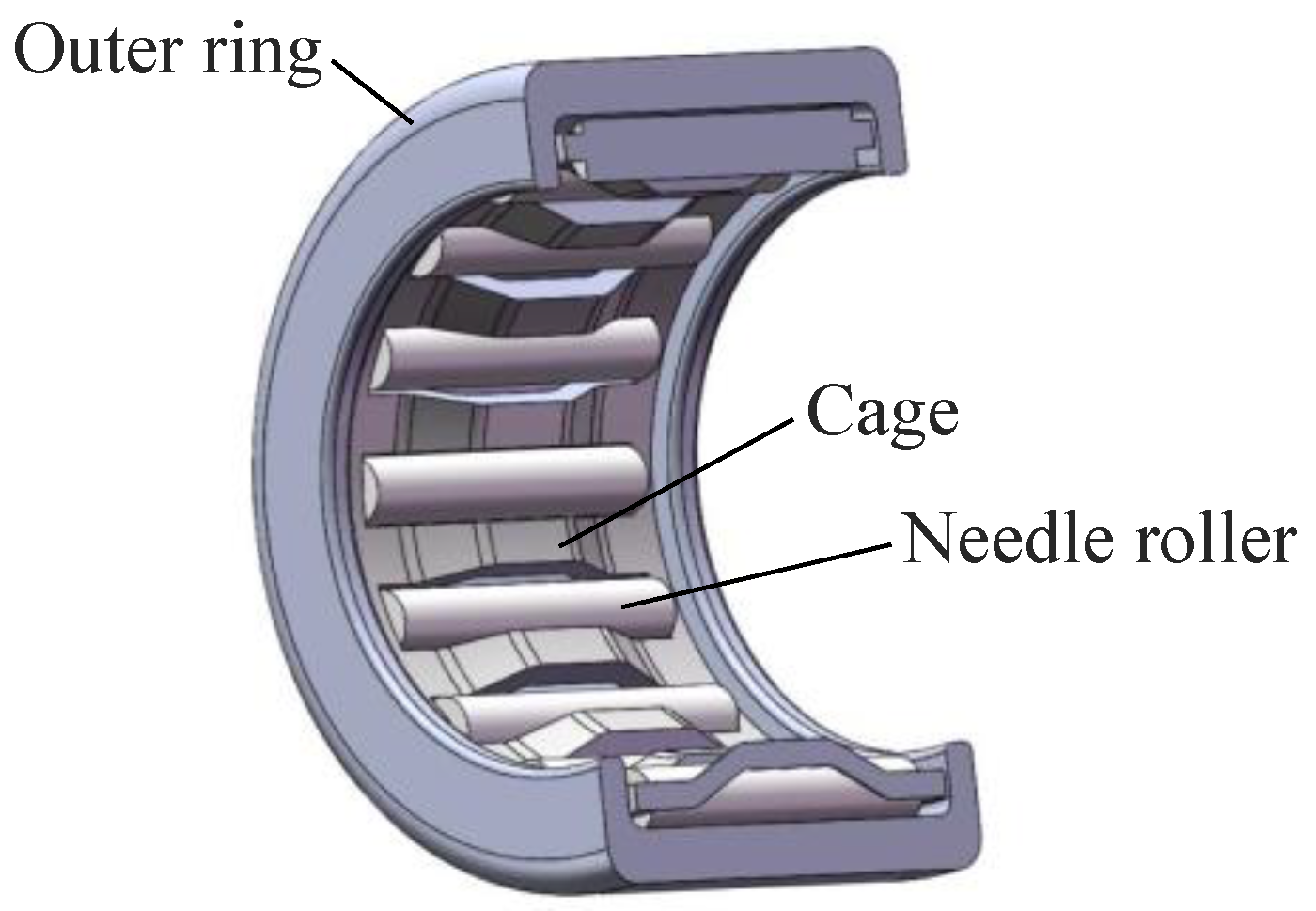
:1. Introduction
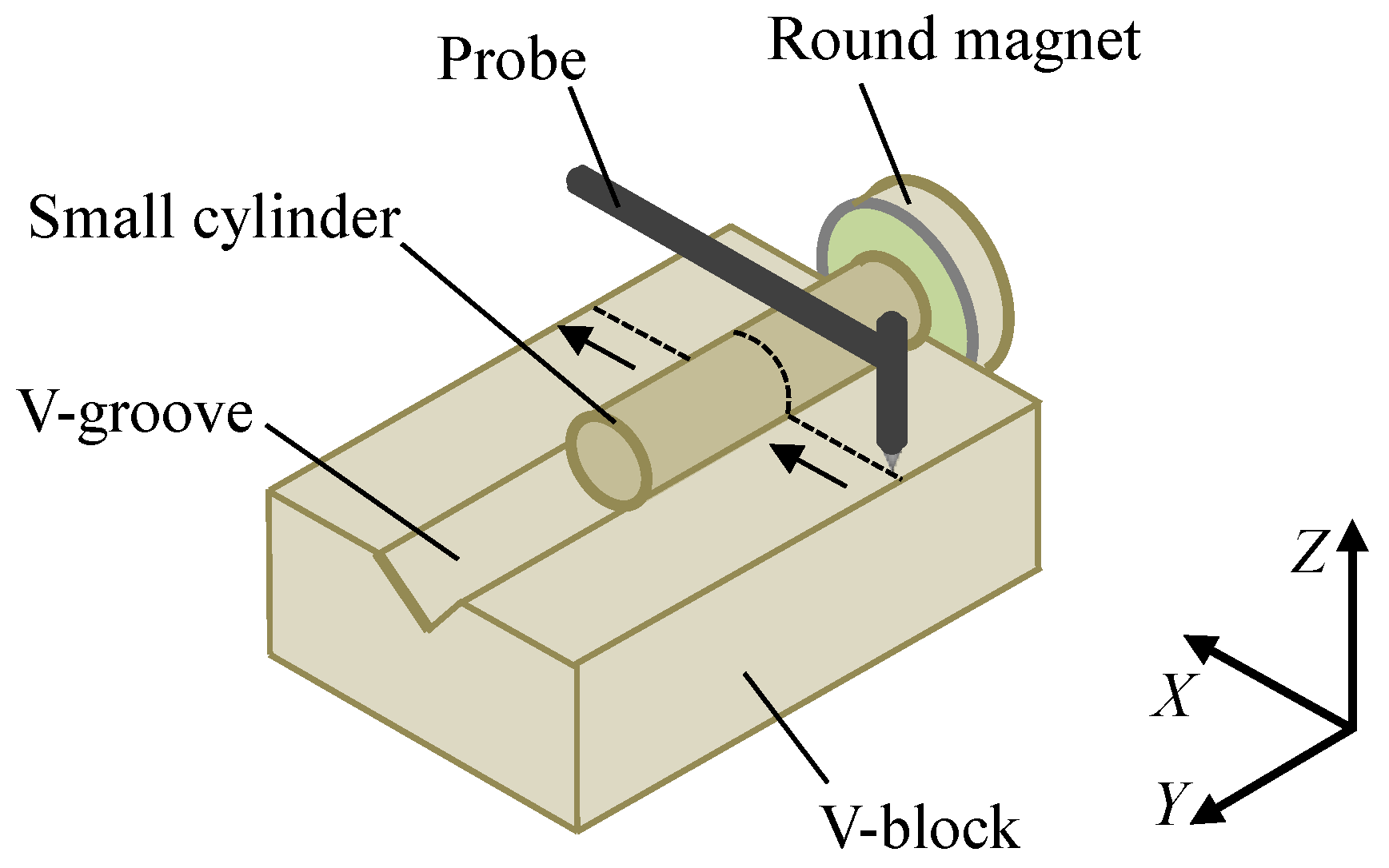
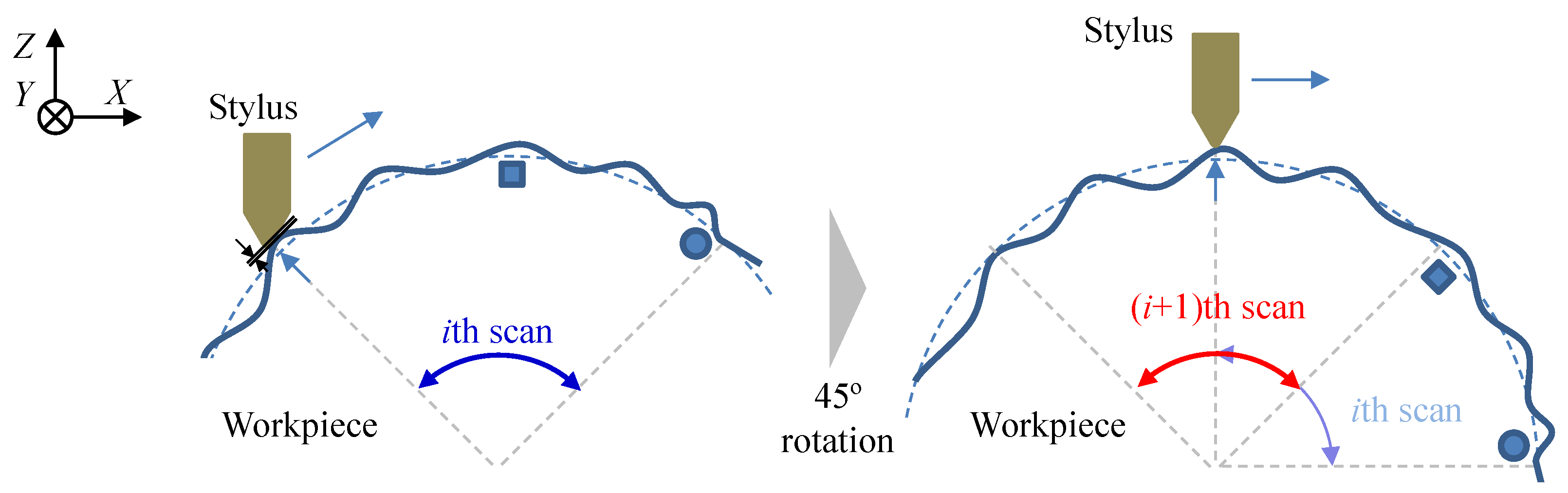
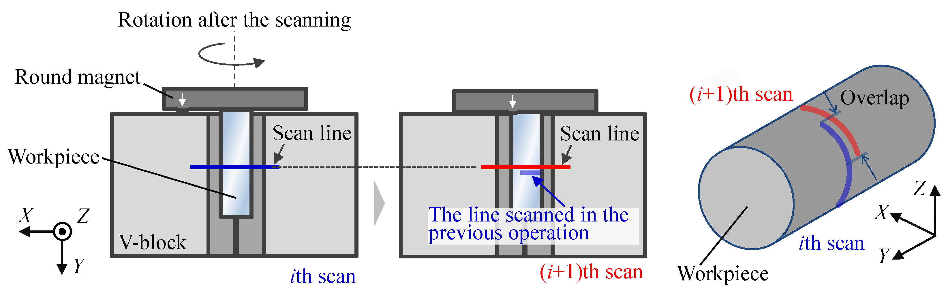
2. Principle of the Stitching Linear-Scan Method
3. Improvement in the Implementation of Stitching Linear-Scan Method
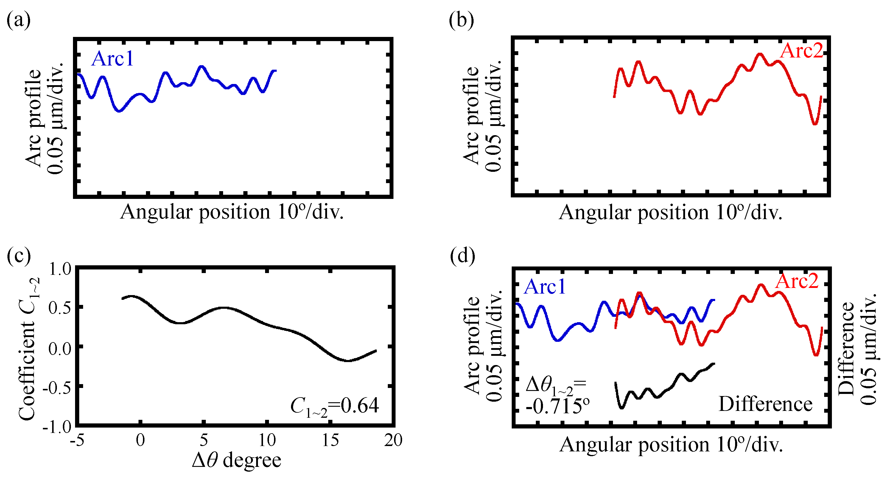
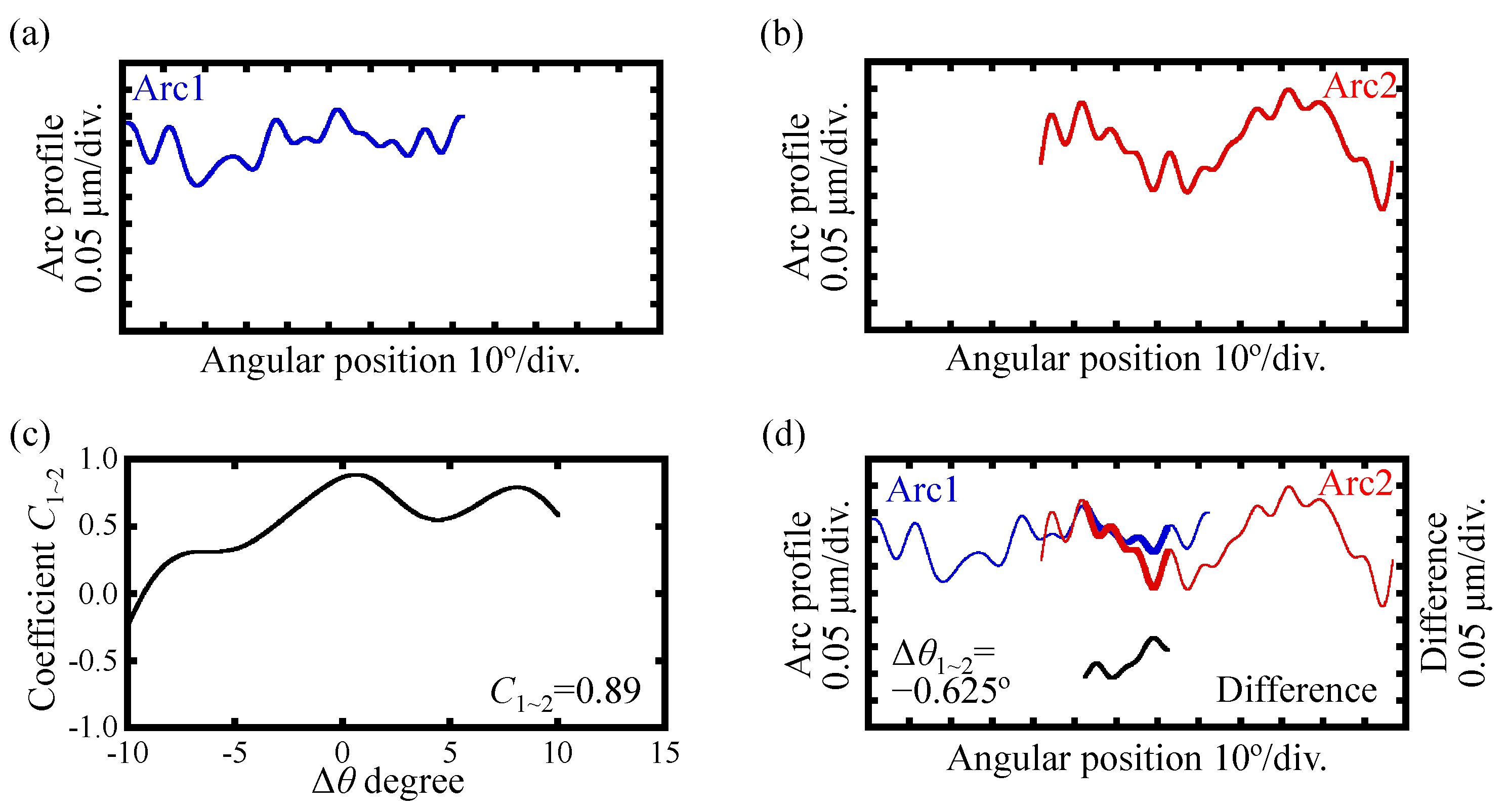
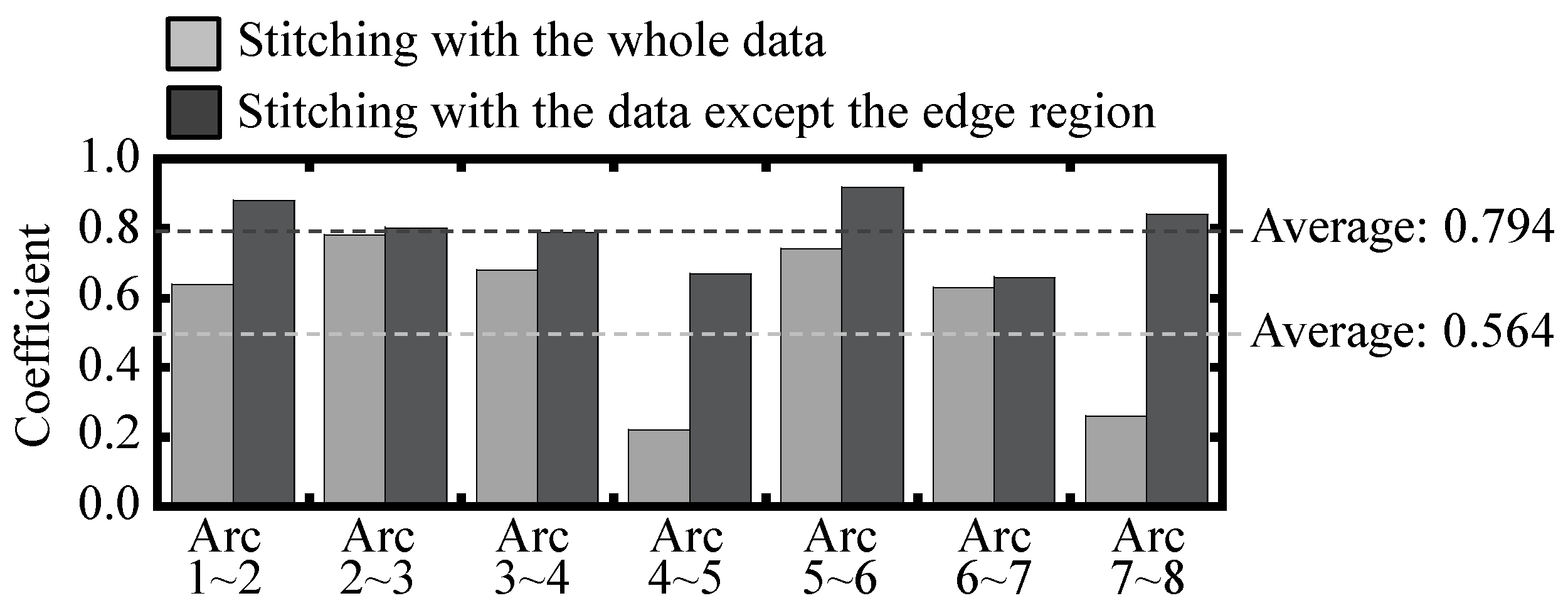
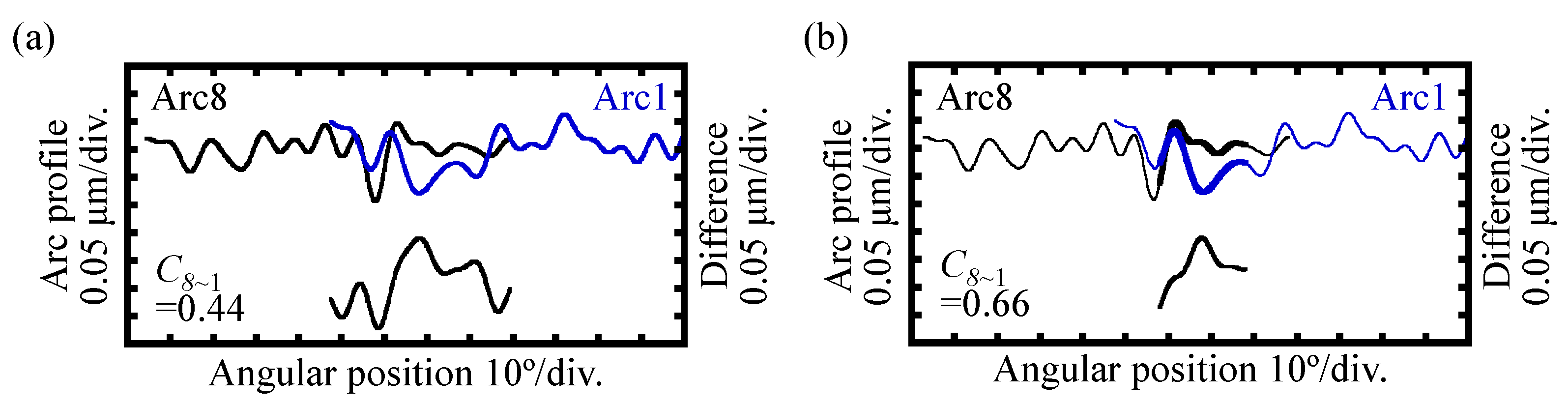
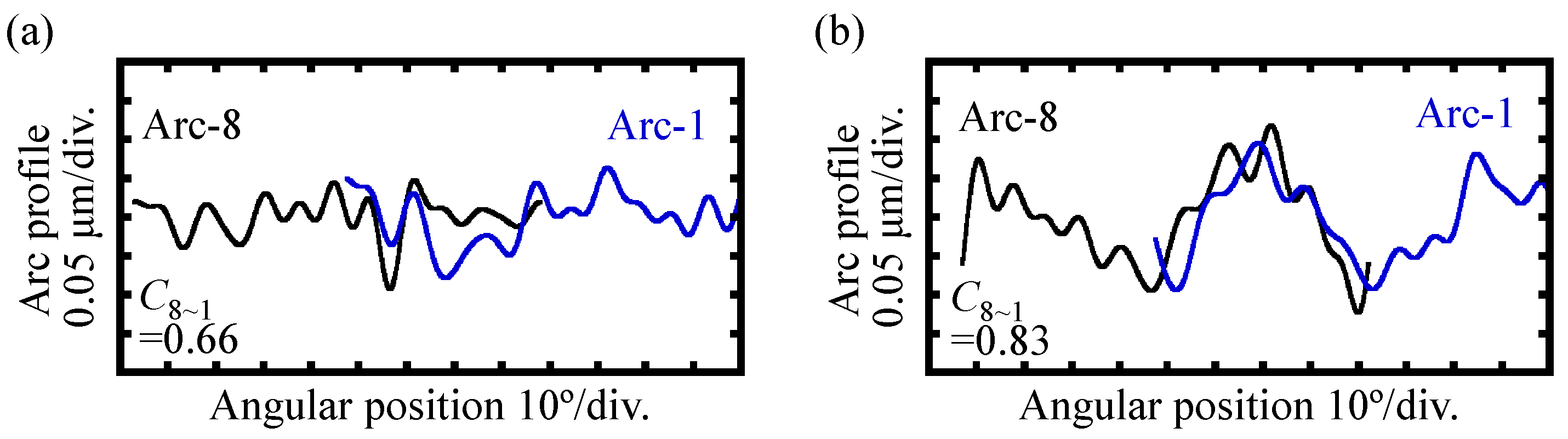
3.1. Improvement of the Cross-Correlation Coefficient in the Circumferential Stitching Process by the Elimination of the Data in the Edge Region of an Arc
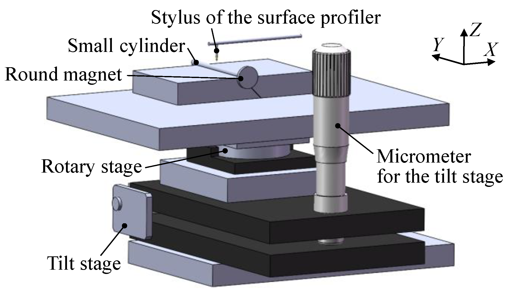
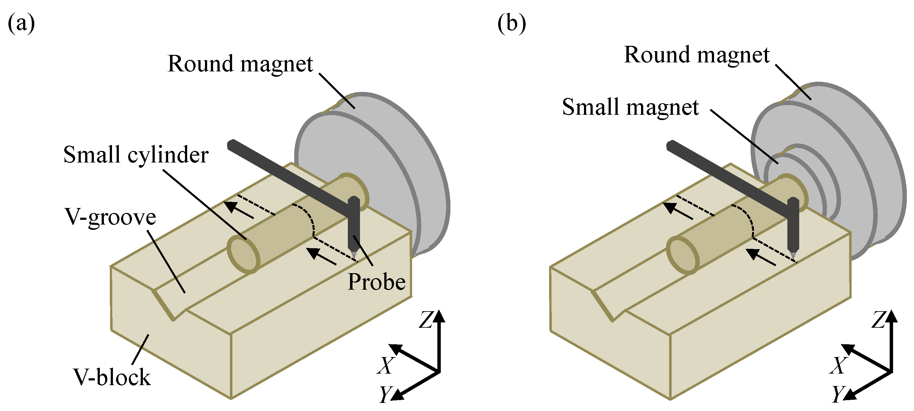
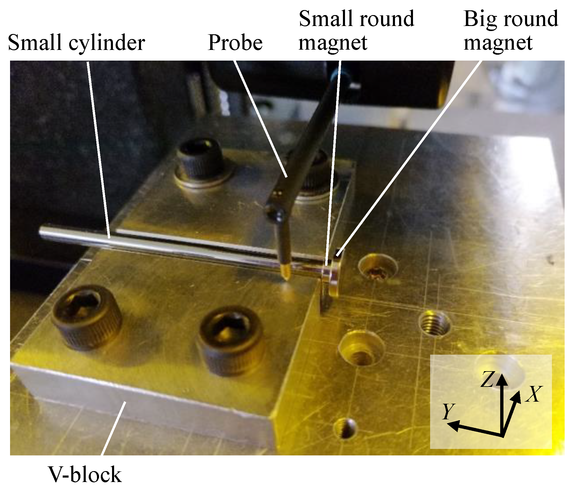
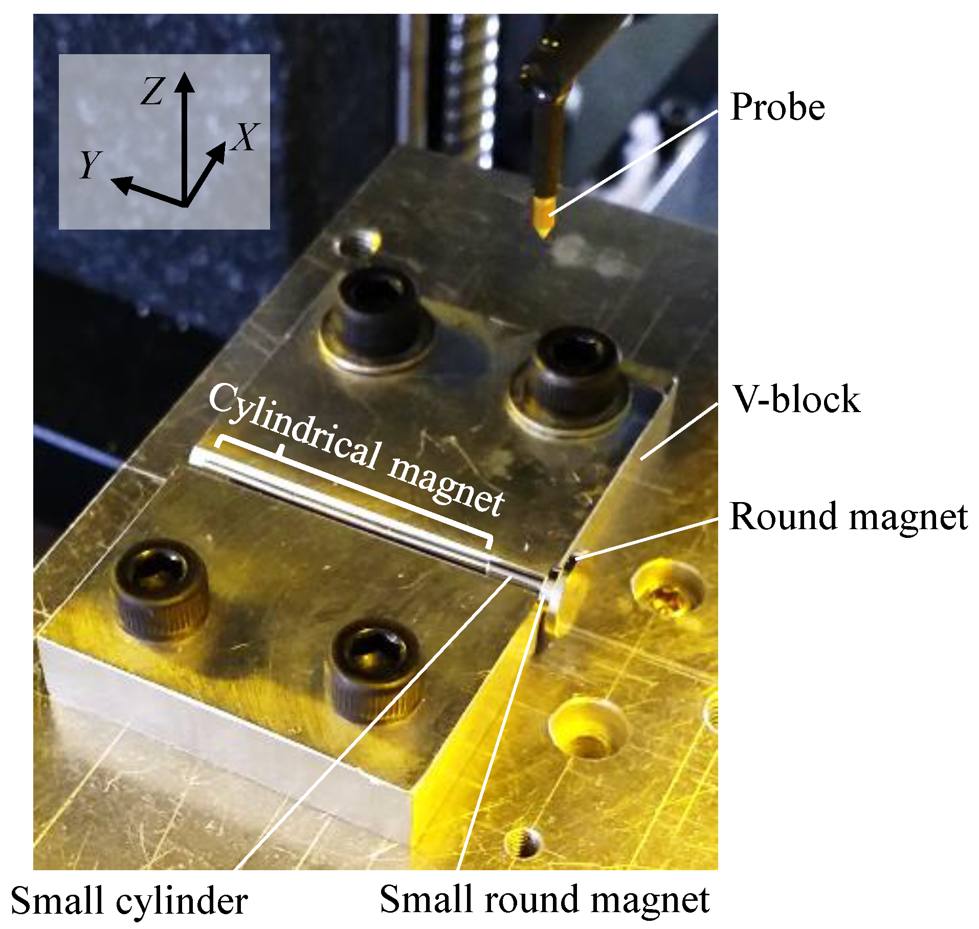
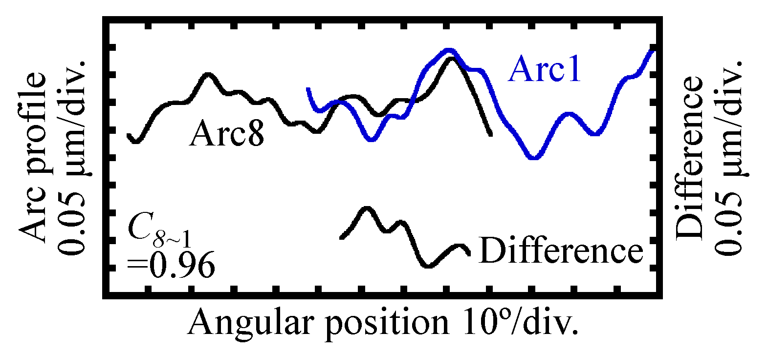
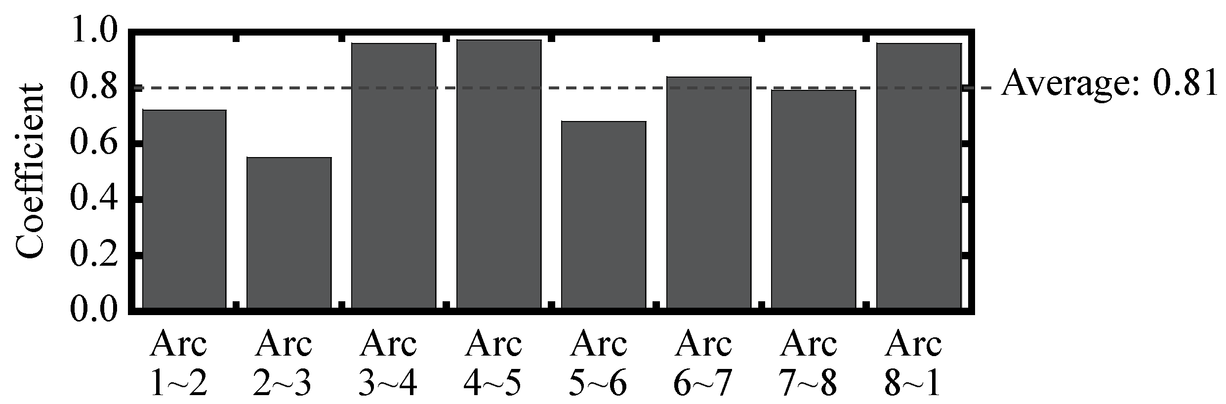
3.2. A Hardware Modification for the Improvement of the Cross-Correlation Coefficient in the Circumferential Stitching Process
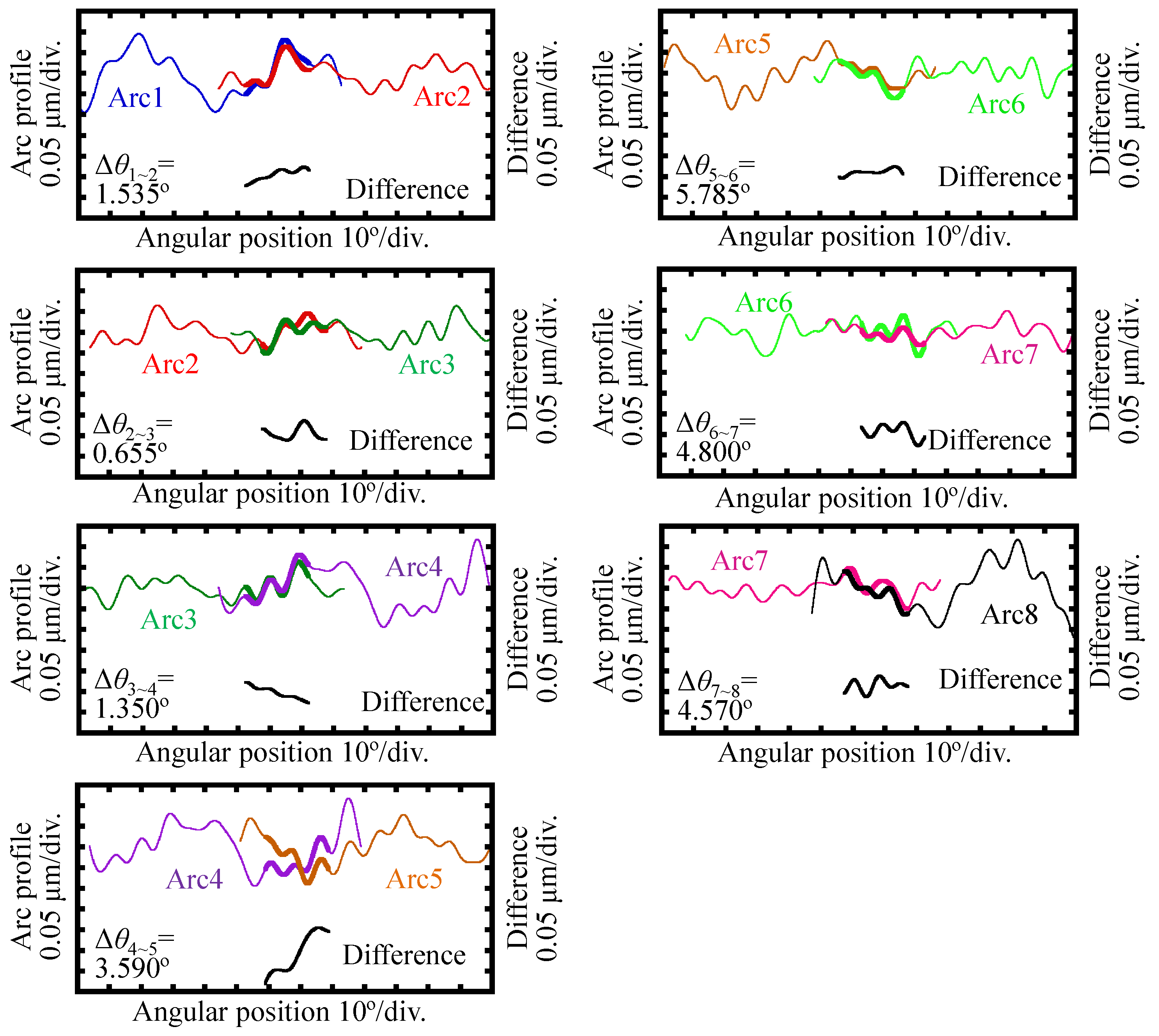
3.3. Implementation of the Stitching Linear-Scan Method for a Workpiece with a Small Dimension
4. Discussion
5. Conclusions
Author Contributions
Funding
Institutional Review Board Statement
Informed Consent Statement
Data Availability Statement
Acknowledgments
Conflicts of Interest
References
- Waghole, V.; Tiwari, R. Optimization of needle roller bearing design using novel hybrid methods. Mech. Mach. Theory 2014, 72, 71–85. [Google Scholar] [CrossRef]
- ISO 12181-1 2003. Geometrical Product Specifications (GPS)-Roundness-Part 1: Vocabulary and Parameters of Roundness; American National Standards Institute: Washington, DC, USA, 2003. [Google Scholar]
- ISO 1206:2001. Rolling Bearings-Needle Roller Bearings, Dimension Series 48, 49 and 69-Boundary Dimensions and Tolerances; American National Standards Institute: Washington, DC, USA, 2001. [Google Scholar]
- Gao, W.; Haitjema, H.; Fang, F.Z.; Leach, R.K.; Cheung, C.F.; Savio, E.; Linares, J.M. On-machine and in-process surface metrology for precision manufacturing. CIRP Ann. 2019, 68, 843–866. [Google Scholar] [CrossRef] [Green Version]
- Haitjema, H.; Bosse, H.; Frennberg, M.; Sacconi, A.; Thalmann, R. International comparison of roundness profiles with nanometric accuracy. Metrologia 1996, 33, 67–73. [Google Scholar] [CrossRef]
- Taylor Hobson Ltd. Roundness Measurement Equipment | Form Measurement | Cylindricity Measuring Instrument | Roundness Tester. Available online: https://www.taylor-hobson.com/products/roundness-form (accessed on 31 March 2021).
- Ding, F.; Luo, X.; Chang, W.; Wang, Z. In Situ Measurement of Spindle Radial and Tilt Error Motions by Complementary Multi-probe Method. Nanomanufacturing Metrol. 2019, 2, 225–234. [Google Scholar] [CrossRef] [Green Version]
- Kühnel, M.; Ullmann, V.; Gerhardt, U.; Manske, E. Automated Setup for Nontactile High-precision Measurements of Roundness and Cylindricity Using Two Laser Interferometers. Meas. Sci. Technol. 2012, 23, 074016. [Google Scholar] [CrossRef]
- Cai, Y.; Xie, B.; Ling, S.; Fan, K.C. On-Line Measurement Method for Diameter and Roundness Error of Balls. Nanomanufacturing Metrol. 2020, 3, 218–227. [Google Scholar] [CrossRef]
- Donaldson, R.R. A simple method for separating spindle error from test ball roundness error. CIRP 1972, 21, 125–126. [Google Scholar]
- Zhang, G.X.; Wang, R.K. Four-Point Method of Roundness and Spindle Error Measurements. CIRP Ann. Manuf. Technol. 1993, 42, 593–596. [Google Scholar] [CrossRef]
- Gao, W.; Kiyono, S.; Sugawara, T. High-accuracy roundness measurement by a new error separation method. Precis. Eng. 1997, 21, 123–133. [Google Scholar] [CrossRef]
- Adamczak, S.; Zmarzły, P.; Janecki, D. Theoretical and practical investigations of V-Block waviness measurement of cylindrical parts. Metrol. Meas. Syst. 2015, 22, 181–192. [Google Scholar] [CrossRef]
- Weckenmann, A.; Bruning, J.; Patterson, S.; Knight, P. Grazing incidence interferometry for high precision measurements of cylindrical form deviations. CIRP Ann. Manuf. Technol. 2001, 50, 381–384. [Google Scholar] [CrossRef]
- Gao, W. Surface Metrology for Micro- and Nanofabrication; Elsevier: Oxford, UK, 2021; ISBN 9780128178508. [Google Scholar]
- Chen, Y.-L.Y.L.; Machida, Y.; Shimizu, Y.; Matsukuma, H.; Gao, W. A stitching linear-scan method for roundness measurement of small cylinders. CIRP Ann. 2018, 67, 535–538. [Google Scholar] [CrossRef]
- Li, Q.; Shimizu, Y.; Saito, T.; Matsukuma, H.; Gao, W. Measurement uncertainty analysis of a stitching linear-scan method for the evaluation of roundness of small cylinders. Appl. Sci. 2020, 10, 4750. [Google Scholar] [CrossRef]
- Helleseth, T. A note on the cross-correlation function between two binary maximal length linear sequences. Discrete Math. 1978, 23, 301–307. [Google Scholar] [CrossRef]
- Pan, B. Bias error reduction of digital image correlation using Gaussian pre-filtering. Opt. Lasers Eng. 2013, 51, 1161–1167. [Google Scholar] [CrossRef]
- Helleseth, T. Some results about the cross-correlation function between two maximal linear sequences. Discrete Math. 1976, 16, 209–232. [Google Scholar] [CrossRef] [Green Version]
- Joint Committee for Guides in Metrology. Evaluation of Measurement Data Guide to the Expression of Uncertainty in Measurement. Available online: https://www.bipm.org/documents/20126/2071204/JCGM_100_2008_E.pdf/cb0ef43f-baa5-11cf-3f85-4dcd86f77bd6 (accessed on 17 May 2021).


| Item | Value | Unit |
|---|---|---|
| Straightness | μm | |
| Measurement range | 0.1–120 | mm |
| Resolution | 0.125 | μm |
| Tip angle of the stylus | 60 | degree |
| Tip radius of the stylus | 2 | μm |
| Scanning speed | 0.1 | mm/s |
| Diameter | Out-of-Roundness | |
|---|---|---|
| Nominal value | 1.500 mm | <0.15 μm |
| Measured value | 1.497 mm | 0.12 μm |
Publisher’s Note: MDPI stays neutral with regard to jurisdictional claims in published maps and institutional affiliations. |
© 2021 by the authors. Licensee MDPI, Basel, Switzerland. This article is an open access article distributed under the terms and conditions of the Creative Commons Attribution (CC BY) license (https://creativecommons.org/licenses/by/4.0/).
Share and Cite
Li, Q.; Shimizu, Y.; Saito, T.; Matsukuma, H.; Cai, Y.; Gao, W. Improvement of a Stitching Operation in the Stitching Linear-Scan Method for Measurement of Cylinders in a Small Dimension. Appl. Sci. 2021, 11, 4705. https://0-doi-org.brum.beds.ac.uk/10.3390/app11104705
Li Q, Shimizu Y, Saito T, Matsukuma H, Cai Y, Gao W. Improvement of a Stitching Operation in the Stitching Linear-Scan Method for Measurement of Cylinders in a Small Dimension. Applied Sciences. 2021; 11(10):4705. https://0-doi-org.brum.beds.ac.uk/10.3390/app11104705
Chicago/Turabian StyleLi, Qiaolin, Yuki Shimizu, Toshiki Saito, Hiraku Matsukuma, Yindi Cai, and Wei Gao. 2021. "Improvement of a Stitching Operation in the Stitching Linear-Scan Method for Measurement of Cylinders in a Small Dimension" Applied Sciences 11, no. 10: 4705. https://0-doi-org.brum.beds.ac.uk/10.3390/app11104705