
Vision-Based Path Guidance to Achieve Dies-Free Roller Hemming Process


_Chang.jpg)
1
Mechanical and Mechatronics Systems Research Labs, Industrial Technology Research Institute, Chutung, Hsinchu 31057, Taiwan
2
Department of Power Mechanical Engineering, National Tsing Hua University, Hsinchu 30013, Taiwan
*
Author to whom correspondence should be addressed.
Appl. Sci. 2021, 11(12), 5741; https://0-doi-org.brum.beds.ac.uk/10.3390/app11125741
Submission received: 31 May 2021
/
Revised: 16 June 2021
/
Accepted: 18 June 2021
/
Published: 21 June 2021
(This article belongs to the Special Issue Metal Forming)
Abstract
:Due to its high production flexibility, roller hemming has become the mainstream process for forming and joining metal sheets in the automotive industry. The traditional roller hemming process requires specific dies to support sheet metal parts and repeated offline manual adjustment of hemming routes, resulting in high die costs, high time consumption, and excessive labor inputs. The universal platform presented in this paper could replace specific dies to effectively reduce costs and expand production flexibility. To reach this objective, a vision-based automatic compensation path to achieve a dies-free roller hemming process is proposed and investigated in this paper. Hand–eye sensor modules assisted by multi-coordinate synchronization calibration for the roller hemming were designed to reconstruct three-dimensional (3-D) shape data of the incoming materials. Results from the proposed system were validated with experimental measurements for the sheet offset and the compensation of the arm hemming position, showing that the single-axis error can be reduced to ≤0.1 mm.
1. Introduction
Sheet metal is the most commonly used component in automobiles, for which stamping is the main forming process. Recently, due to increasing demand for lightweight vehicles, automakers have introduced aluminum alloys or high-strength steels to replace traditional steels. With the inclusion of the new materials, many innovative metal forming processes have been derived. Hot/warm forming processes proposed and investigated by Maeno et al. [1], Talebi-Anaraki et al. [2], and Talebi-Anaraki et al. [3] are innovative forming processes to solve the problems of insufficient ductility of aluminum alloys and spring-back of high-strength steels.
Hemming on the other hand is a sheet metal forming and joining process used in the automotive industry to join inner and outer closure panels and components. Such panels or components include hoods, doors, trunk-lids, tailgates, etc. This hemming processing is the process of bending/folding the edge of the outer part (skin) over the reinforcing inner one, which largely represents and determines the external quality of the final automotive products. Common hemming equipment can be catalogized into classical hemming (hem die-central), table-top hemming, robotic roller hemming, etc. In recent years, in order to achieve cost reduction and increase manufacturing flexibility, the industry has been phasing out expensive technologies, such as classical hemming, and transforming into the use of more economical means of production. Due to the high production flexibility of robotic roller hemming, it has become the mainstream process for joining metal sheets in the automotive industry.
In the past, most hemming studies focused on simulating and analyzing the properties of materials, the complex interactions between geometric shapes and process parameters, or predicting the final quality and defects of parts. The approach used in the literature mainly includes finite element (FE) simulation of the roll hemming process. For instance, Thuillier et al. [4] utilized FE to investigate the roller hemming process on an Al-Mg alloy. Arroyo et al. [5] used FE simulation to accurately predict the geometry of the part before hemming, and also the required forces for the hemming operation. Hu et al. [6] conducted numerical analysis of the roller hemming process; they found that evolution of the load on the roller, resulting in plane strain bending of the part, varied during the course of the hemming process. Gürgen [7] studied the influence of hemming parameters, such as bending angle, thickness, and roll diameter, on the hemming force and final quality of the products. Other researchers proposed some novel strategies for hemming. For an example, Jimbert et al. [8] used electromagnetic forming (EMF) for an aluminum sheet hemming process. Laser heating to assist the roller hemming process was proposed by Kleeh et al. [9,10] who discussed the effect of increasing heat in the hemming process on aluminum sheet metal after forming. Dewang and Sharma [11] presented a systematic review of the sheet metal hemming processes.
Due to increasing market demand and the trend fo small-volume, large-variety production, saving costs while increasing productivity has become a common research and development focus in the automotive industry. However, in present practice, even the highly flexible robotic roller hemming still requires specific dies to support the sheet metal parts. In the present robotic roller hemming, the repeated and offline manual adjustment of the robot planning route is required, which has been found to result in high die costs, time consumption, and labor costs. The goal of the research presented in this paper was to solve this issue. With the proposed method of vision-based automatic compensation path guidance that is discussed in detail in the following sections, a universal fixed platform replacing specific dies is feasible, which allows for a dies-free roller hemming process that further reduces costs and expands production flexibility.
2. Experimental Apparatuses and Methodology
2.1. Experimental Apparatuses
A universal fixed platform was designed to replace a specific die, which is used to support and fix parts in the hemming process. As shown in Figure 1, the platform consists of an aluminum extrusion frame, rotating motor, and multiple pneumatic clamps and vacuum chucks, which together allow for changes in the fix position and angles to fit different types of parts.
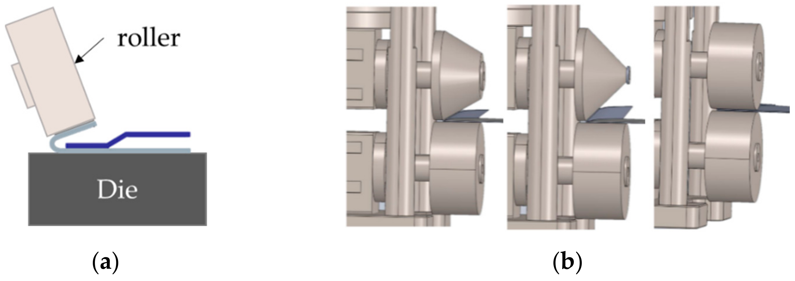
As there is no special die to serve as the underneath supporting surface when the sheet metal part is hemmed by rollers, the traditional hemming tool such as the single roller as shown in Figure 2a has to be redesigned and transformed into the active double-roller as shown in Figure 2b. In the active double-roller design, the lower roller or wheel serves as the supporting structure whereas the upper roller can be actively controlled pneumatically to open and close against the lower roller to exert force onto the sheet metal. The shape of the upper roller can be changed to meet the needs of different forming angles.
2.2. Hand–Eye Sensor Module
It is well known that if the rollers can correctly follow the curve of the work piece and keep good and stable contact with the sheet metal surface during the hemming process, most of the defects caused by improper force can be effectively eliminated or at least minimized. For this reason, it is very important to eliminate position deviation that is introduced and caused by manufacturing tolerances, the sheet metal deflection deformation, and the assembling tolerances of the working platform, especially when there is no special die to offer data for aligning the parts in the system. In order to overcome the above-mentioned problems, the compensation of the hemming path must depend on reconstruction and analysis of the three-dimensional (3D) data after the work piece is positioned. Obtaining reconstruction data and coordinate accuracy will affect the final product quality, mainly in the rolled-over edges, i.e., the roll-in, roll-out, warp, and recoil by the rollers. Therefore, we proposed and designed a hand–eye sensor module for roller hemming to achieve the purpose of reconstructing the 3D shape data of the incoming materials.
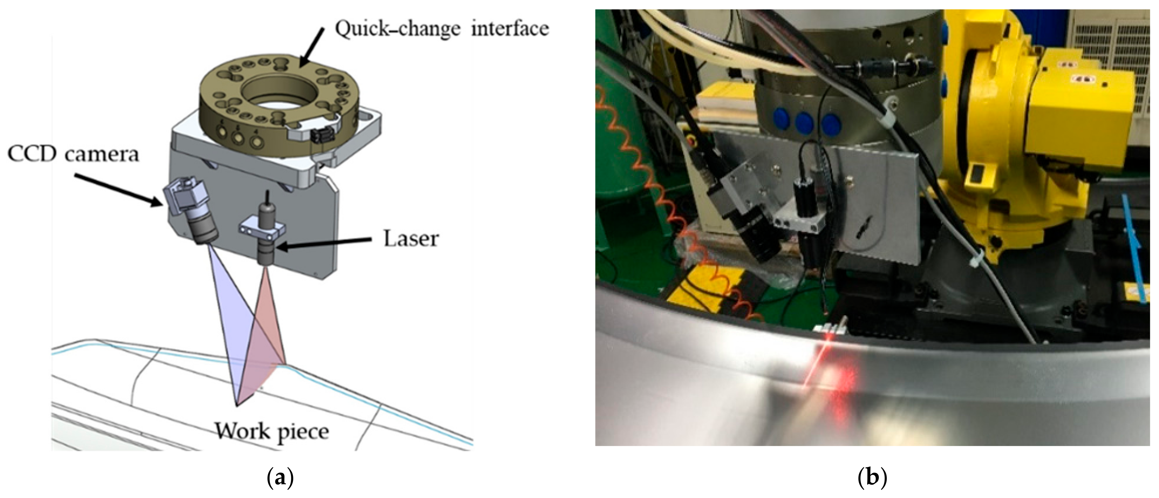
In 2013, Swillo [12] designed a new portable vision-based measurement system for the hemming process. It was demonstrated that quick and accurate analysis of the geometry and deformation of hemmed samples can be achieved. Following Swillo’s original design, an enhanced vision measurement module, namely the quick-change sensor module as shown in Figure 3, was proposed and constructed. This quick-change sensor module can be easily installed onto and released from the robotic arm through the quick-change interface. Once it is installed on to the robotic arm, this sensor module can be used to scan over time to determine the position and posture of the sheet metal work piece. The sensor module consists of a laser emitter and a CMOS image receiver. The laser emitter projects a line pattern onto object surface, from which the reflecting light of the projected pattern on the contour of work piece can then be captured by the CMOS image receiver to determine and estimate coordinates of the projected line. A series of coordinates are acquired by simultaneously scanning over the hemming path, and thus forming the 3D model of the metal sheet around the hemming path.
The quick-change sensor module has a built-in battery to avoid the process of module restart and reinitializing due to lack of power each time it is disconnected and reconnected to the robot arm. The quick-change interface as illustrated in Figure 4 not only serves as the interface for the sensor module but also for the hemming tool. It is divided into two parts, namely the main plate and the tool plate. The main plate is installed on the flange surface of the robot arm, and the tool plate is installed on the top of the sensor module and the hemming tool. With this quick-change interface, the robot arm can quickly replace the hemming tool or sensing module within 5 s through the combination and separation function of the main board and the tool board.
2.3. 3D Surface Reconstruction and Coordinate Calibration Methodology
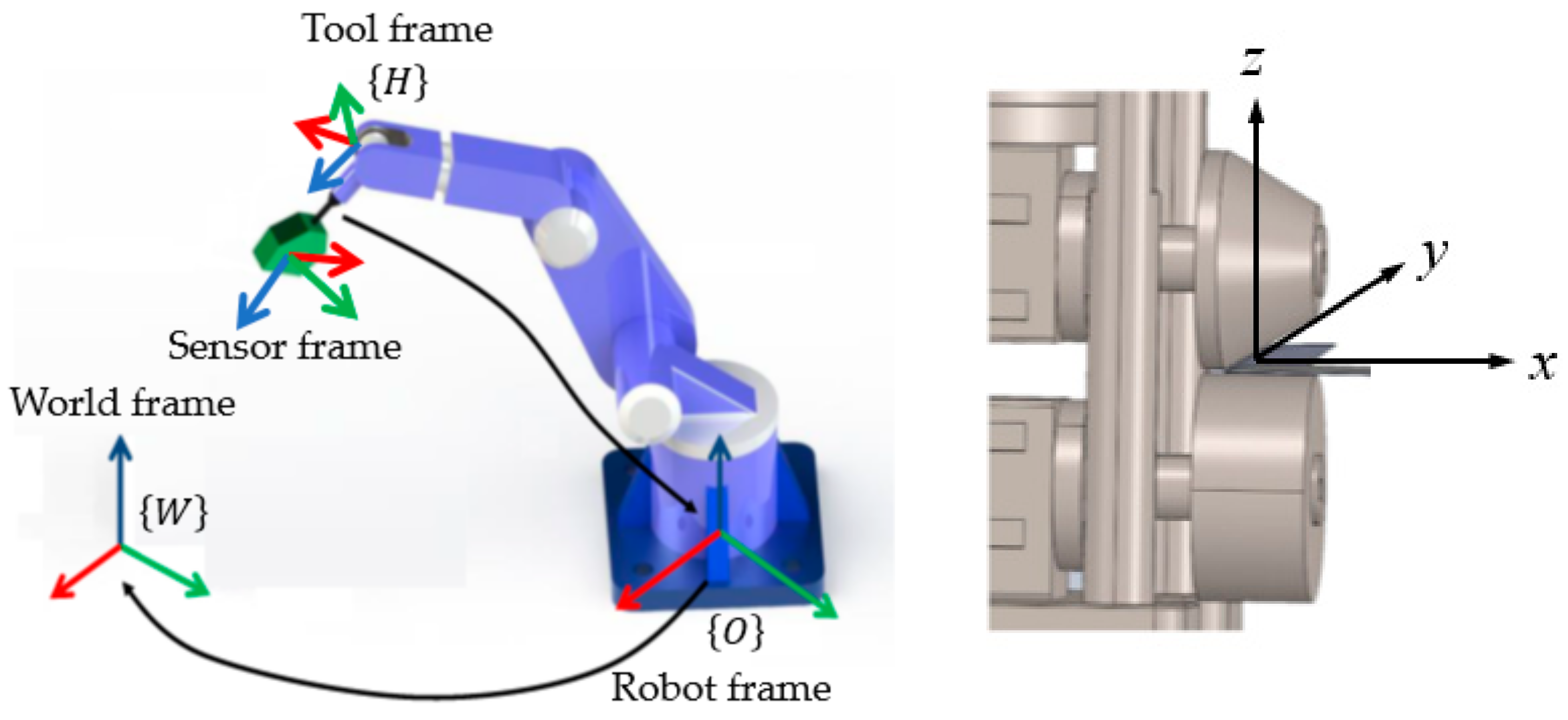
In order to estimate the 3D coordinates from the sensor module, the poses, including positions and orientations of the image receiver and the laser emitter, are calibrated relative to the hemming tool using the hand–eye calibration method [13,14]. As shown in Figure 5, the hand–eye coordinate system includes the world frame (also called the user frame), the sensor frame, the tool frame, and the robot frame. The location of the sensor frame is placed at the matching point of the two rollers with its y-axis pointing along the roller’s circumferential direction, with the z-axis being perpendicular to the lower roller’s surface and the x-axis being perpendicular to the y-axis and z-axis. In order to transform the measured coordinates from the sensor frame into the world frame, a multi-frame transformation is performed to solve the rotation and translation relation between the robot and the sensor module. This operation uses a transformation matrix, which contains a rotation matrix and a translation vector in the form of
where is the rotation matrix of the frame {A} to {B}, is the translation vector of {A} to {B}, and the rotation matrix adopts X-Y-Z fixed angles to calculate the rotation angles α, β, and γ, respectively. This rotation matrix can then be expressed as
By using the above conversion matrix to convert each layer, the coordinates converted from the world frame {W} to the sensor frame {L} are calculated by the conversion calculation process as shown in Figure 6. The conversion relationship between the robot coordinate and end-effector coordinate is known through the built-in encoder of the robot arm. The relationship between the world frame {W} and the robot frame {O} and the hand-to-eye relationship can be calculated by the size of the sensor and the connector, although it can easily be affected by manufacturing tolerances and assembly errors leading to poor accuracy. Therefore, the relationship between the world frame {W} and the robot frame {O} and the hand–eye relationship need to go through the calibration procedure to achieve better accuracy.
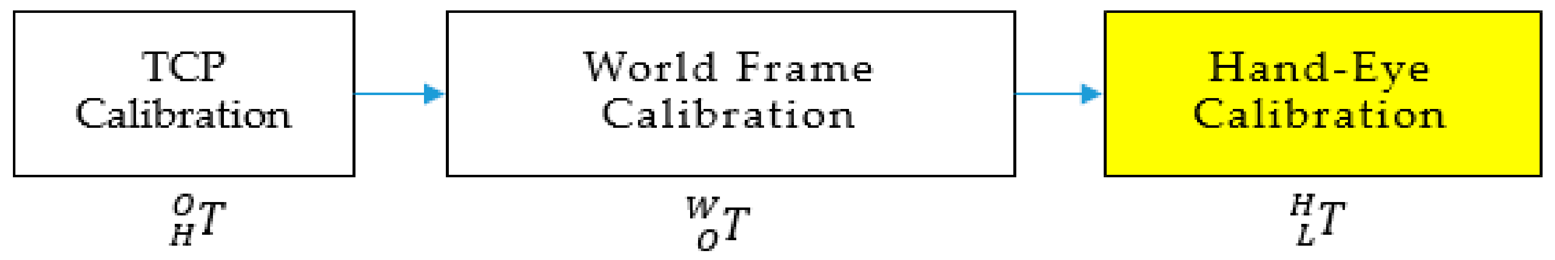
Figure 7 shows the calibration procedure used in this research. Firstly, calibration is conducted for the robot tool frame to find out the conversion relationship between the tool center point (TCP) of the robot and the default tool frame. This calibration allows the robot arm to calculate the position and orientation of the end-effector, which means the conversion relationship between the end frame and the robot frame. Then, the conversion relationship between the world frame and the robot frame is calibrated by the known . Finally, through and , the hand–eye relationship can be calibrated and established to obtain the conversion relationship between the sensor frame, the eye, the end-effector frame, and the hand of the robot arm.
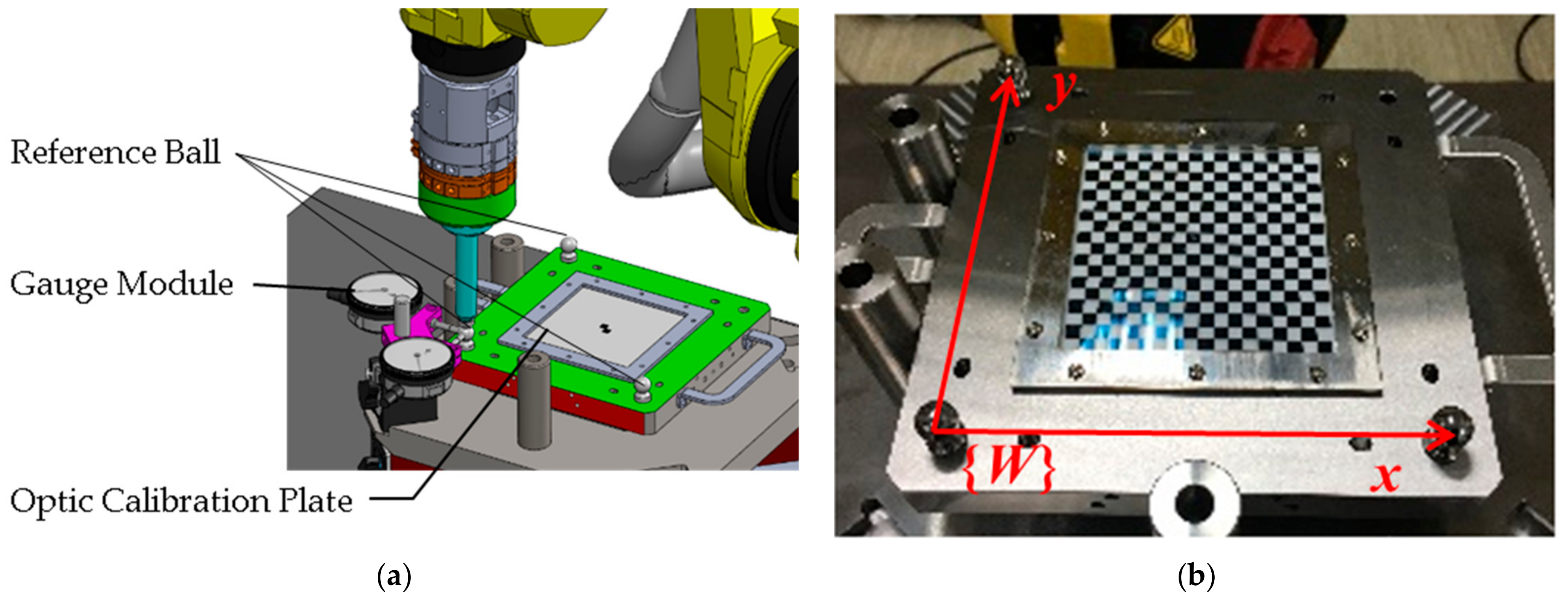
In order to perform the above calculation and proceed with the calibration, a calibration device as shown in Figure 8 was designed and used for establishing the references of the sensor. This device is composed of three modules, namely an optic calibration plate, the reference ball used to establish the robot reference, and the scale block used to identify the XYZ position of the robot TCP.
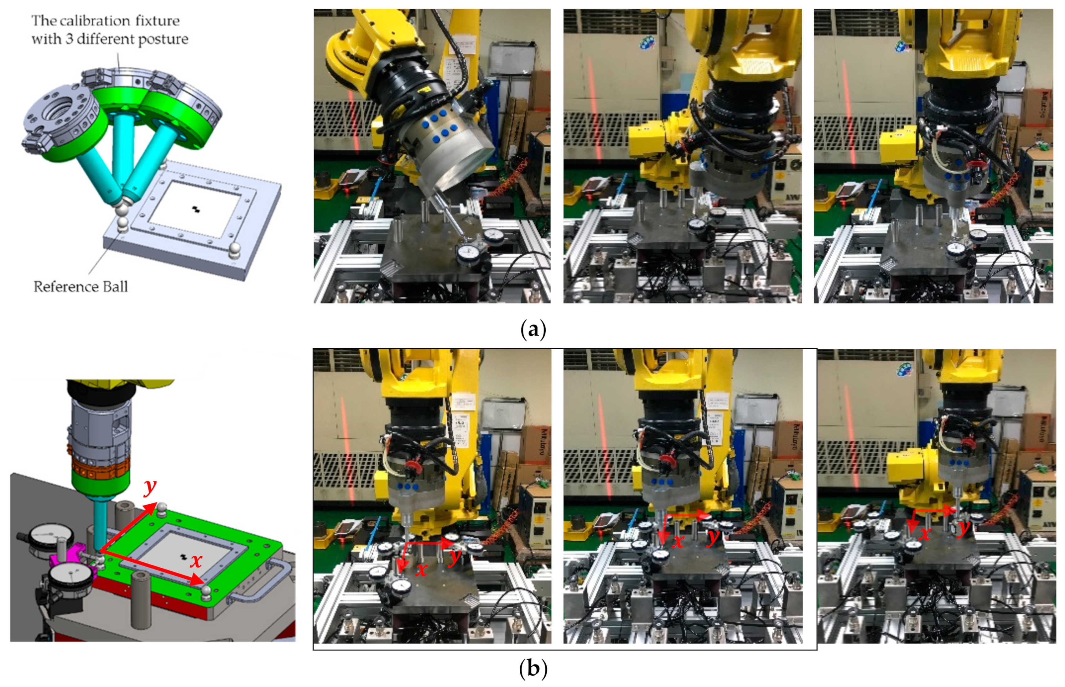
The conversion relationship from the robot arm frame {O} to the robot arm end frame {H} is calibrated using the following steps. First, the calibration jig is installed to the original TCP of the robot arm as a hemming tool. Since the designed fixture size is the same as the actual hemming tool, the end-effector frame {H} can be calibrated by aligning the hemming tool frame. Secondly, the robot arm is manipulated with the calibration jig to the origin of the calibration module at three or more different angles as illustrated in Figure 9a. In this step, one needs to let the spherical device on the front of the jig lightly touch the meter module to make the meter module produce displacement readings. According to the changes of the readings, the endpoint of the calibration fixture with different postures can be adjusted to the same position, thereby reducing the influence of the gap within the robot itself on the calibration accuracy. When multiple postures are recognized, the last step is to calculate the conversion relationship between the end frame and the original robot arm TCP frame to obtain the transformation matrix from the robot arm frame {O} to the end-effector frame {H}.
The calibration procedure for the world frame is similar to the above-mentioned TCP calibration process. After installing the calibration fixture on the end of the robot, one needs to manipulate the robot to touch the origin’s X-direction point and Y-direction point of the world frame {W} with the same posture as shown in Figure 9b. According to the readings of the gauge module, one then proceeds to fine-tune the end position of the robot arm to confirm the alignment with the calibration module. After which process, the transformation matrix describing the transformation from the world frame {W} to the robot frame {O} can then be derived from the current posture of the robot arm.
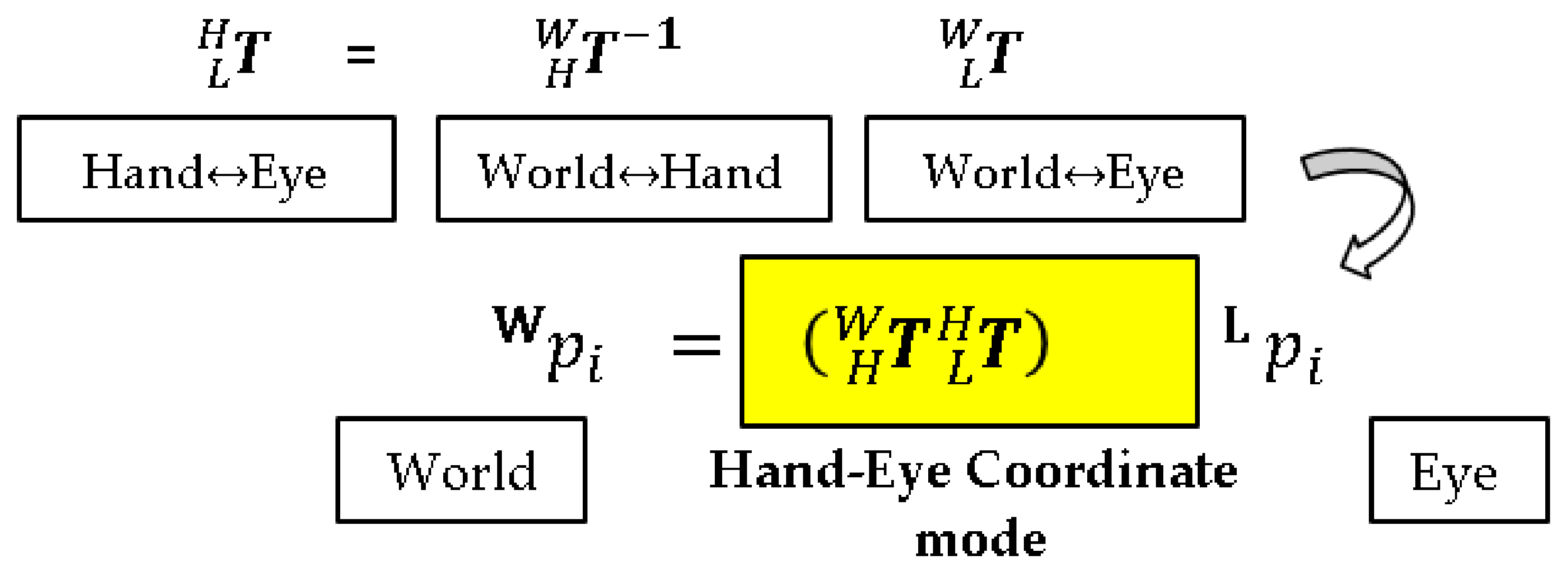
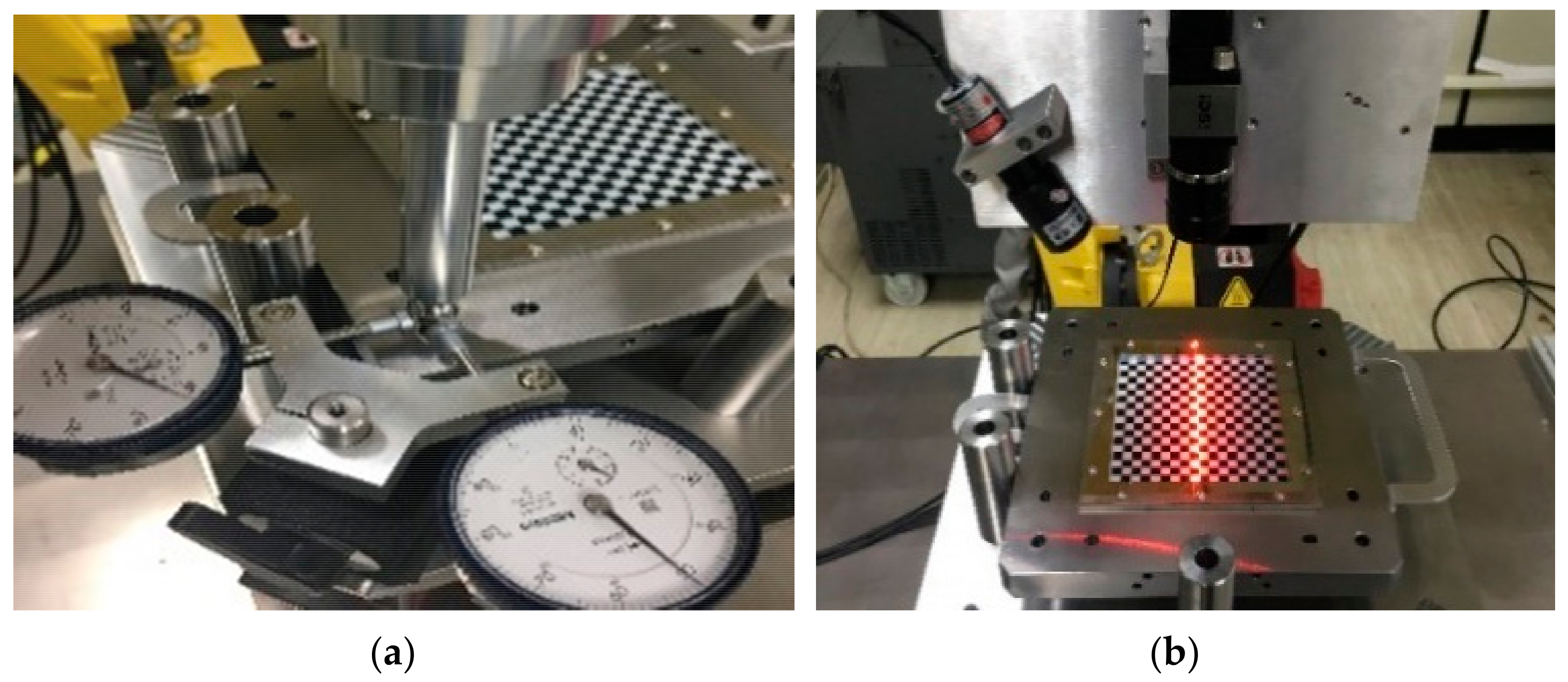
The last step is the calibration of the hand–eye relationship. The purpose of this is to calibrate the conversion relationship between the sensors and the end frame of the robot, so that in the future, the data can be directly converted into the world frame through the robot’s posture during the sensing process. As shown in Figure 10, the calibration method of this item needs to align the sensor module with the optic calibration plate in the center of the calibration device, and it uses the device’s black and white checkerboard grid points to perform vision correction and calculate the 3D conversion relationship with the optic calibration plate. Next, through the known position of the optic calibration plate in the world frame, the conversion relationship of the sensor relative to the world frame can be derived. In the meantime, not only are the postures of the robot recorded, but the conversion relationship of the end-effector of the robot under the world frame is calculated and obtained at the same time. Using the following formula, the hand–eye relationship can then be further derived. After calibrating the hand–eye relationship, the points scanned by the sensor can be transformed from the sensor frame into the world frame.
2.4. Hemming Path Adjustment
After completing the above-mentioned calibration procedure, the 3D surface model of the actual workpiece can be reconstructed by the scanned data. Because a general working platform instead of a special die was used in this study, there is no supporting surface for the reference or alignment point under the sheet metal. In this situation, the working posture theoretically is non-ideal. As such, if an ideal hemming path that is generated from the ideal CAD model is used, hemming failure and defects will certainly occur. On the other hand, the real hemming path that will adapt to such deviations can be generated and obtained through the 3D reconstructed surface model. This real hemming path, which apparently is different from the ideal hemming path generated by the CAD model, can be used to overcome the position deviation caused by the manufacture tolerances, the sheet metal deflection deformation, and position errors introduced by loading-unloading of the work pieces.
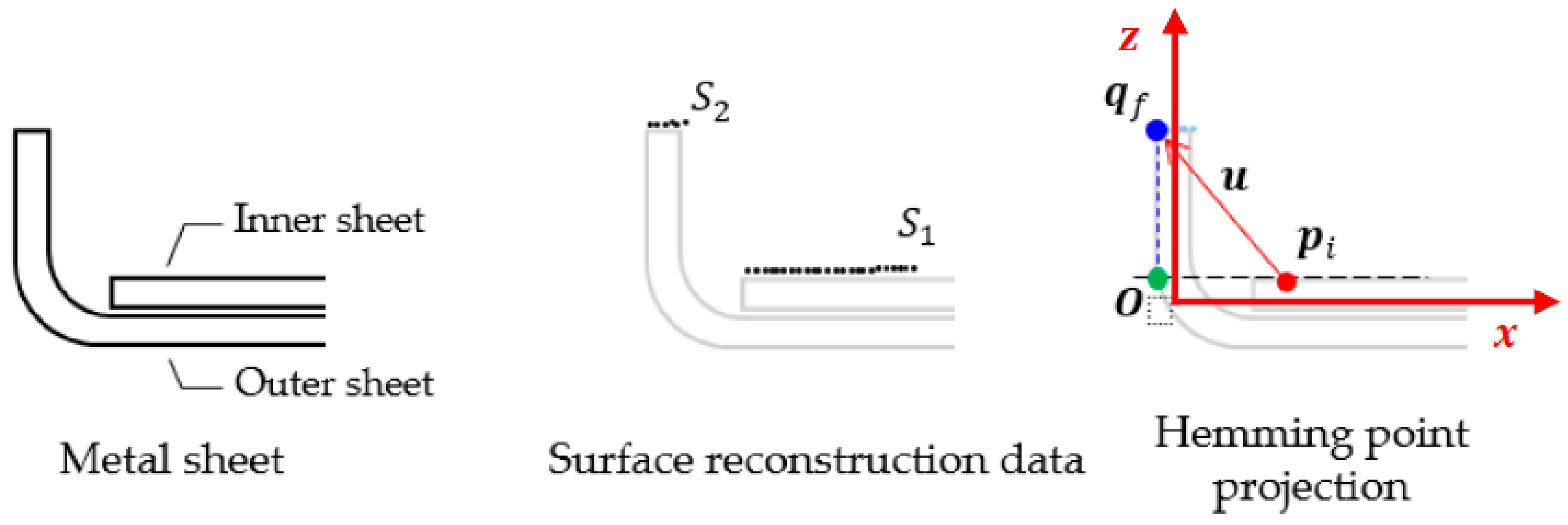
For an illustrated example to explain how the actual hemming point can be estimated, please see Figure 11: Take the surface model of the inner sheet S1 as a reference line, the projection point, marked by , of the tip of the outer sheet S2, denoted as , on this reference line can be calculated to obtain the actual hemming point O. Since the sensor coordinate {L} is only on the X-Z plane, each slice of the 3D surface model can certainly be reduced to a two-dimensional plane.
The reference line equation is defined as
where are the horizontal and vertical coordinates of the point in S1, respectively, and the cost function is expressed as
where n is the amount of 3D points . To obtain the parameters a and b so as to minimize , a partial derivative is performed on with the following calculation.
Through singular value decomposition (SVD), the optimal x can be obtained from the minimal eigenvector of matrix . When a and b are obtained, by calculating the flange point from the 3D model , and subtracting any point on the reference line to obtain vector , the hemming point O can then be solved by projection of onto the vector . After each path point is calculated from the scanned data cloud, that is the data points that form a cloud, the hemming path is in fact the collection of all the path point coordinates that are calculated through the above process.
3. Verification and Results
3.1. Hand–Eye Relationship Calibration Results
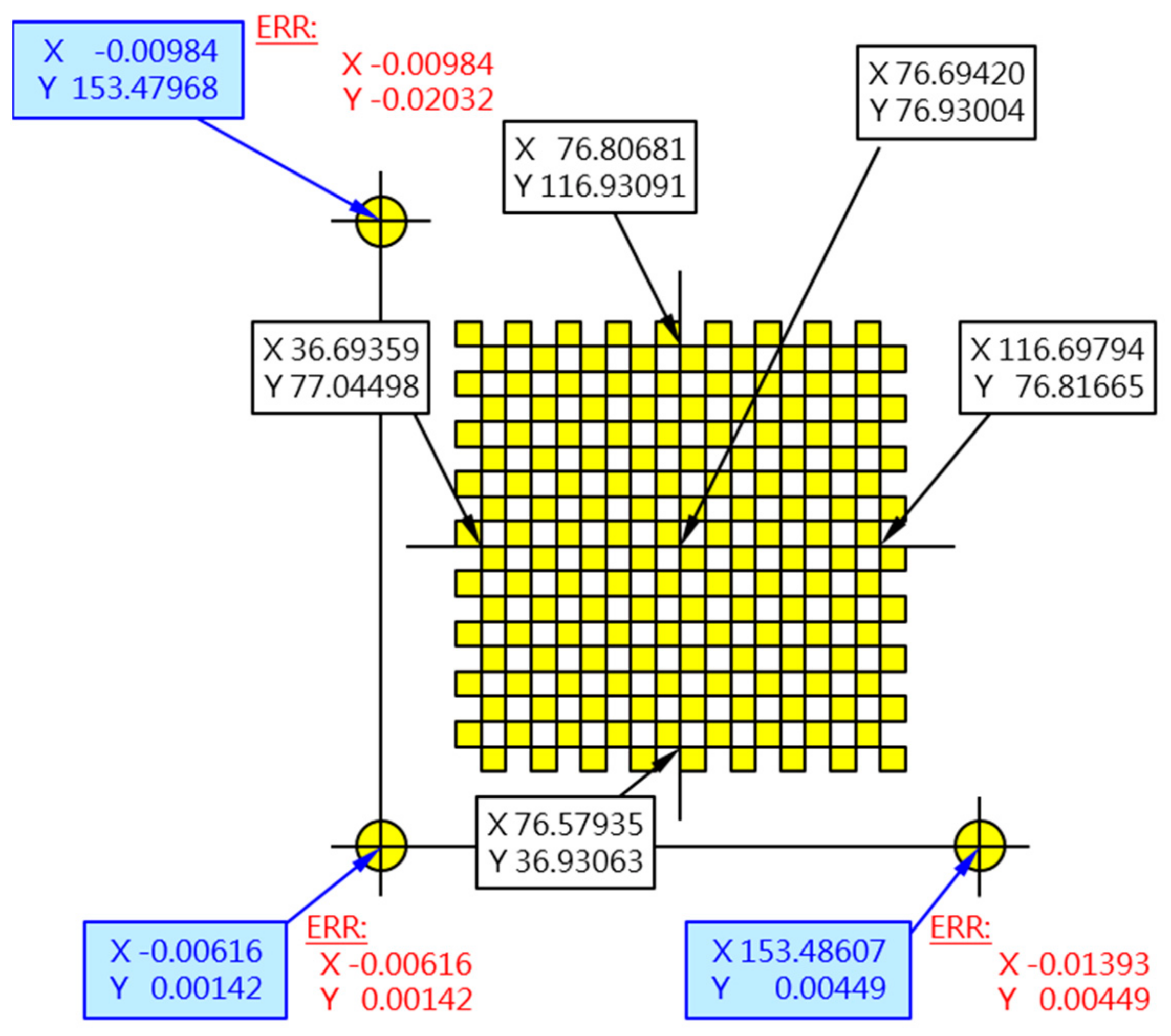
Before conducting the hand–eye relationship correction, the device employed for the correction must be sent to the TAF-approved mechanical characteristic testing laboratory (TAF0039) for measurement, to check the geometric accuracy and to confirm the correctness of the reference frame. The measurement results of the optic calibration plate and the reference ball coordinate are shown in Figure 12. Some of these measurement values will be used for calibration calculation to improve calibration accuracy.
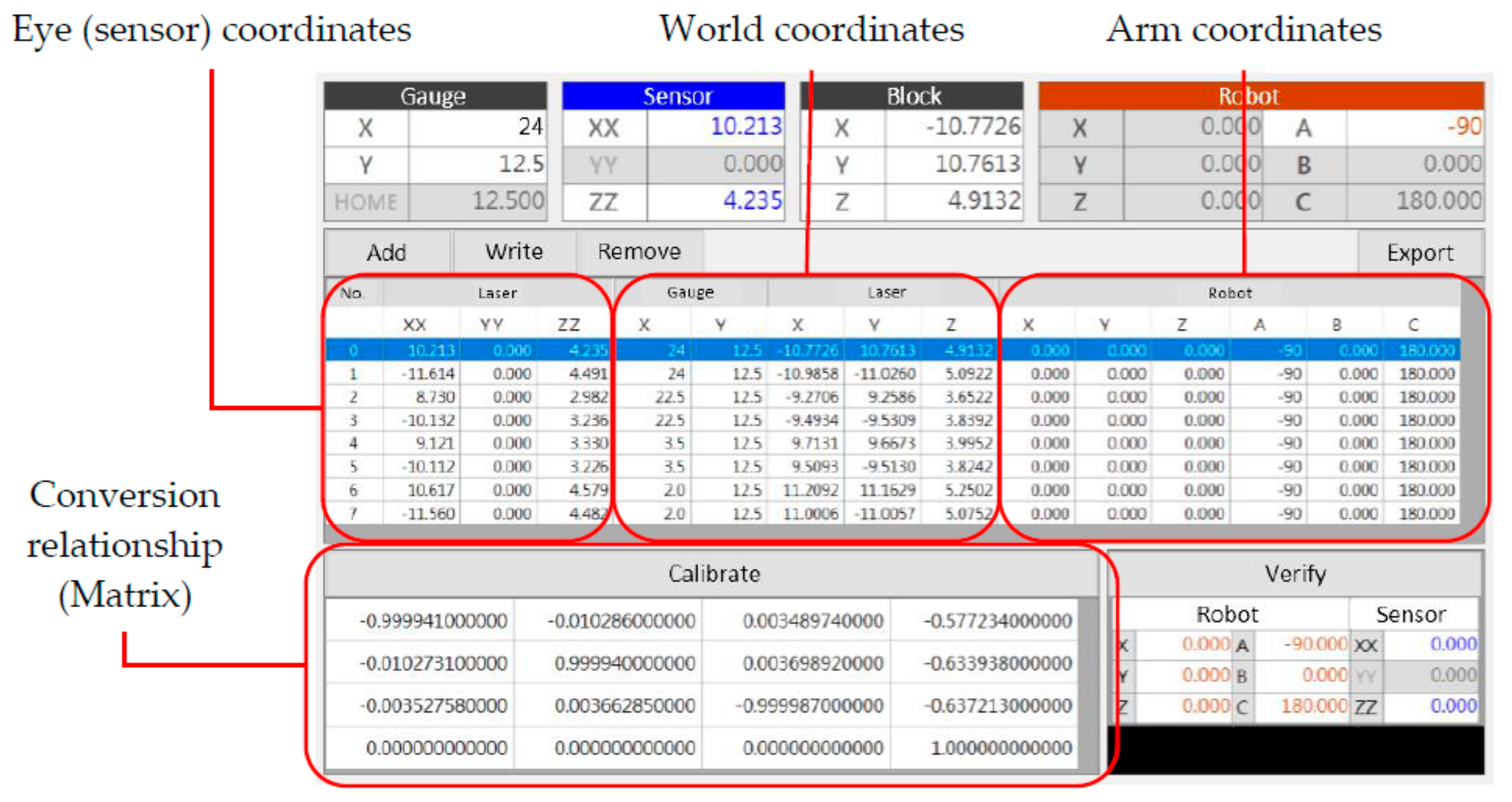
Following to the coordinate calibration methodology as described in Section 2.3, a self-developed hand–eye relationship calibration software is used in this work to perform matrix and coordinate conversion calculations. Such calibration software is outlined in Figure 13. After the coordinate conversion calculation, the conversion relationship between the world frame and the robot frame can be calibrated.
3.2. Sensing Accuracy Verification
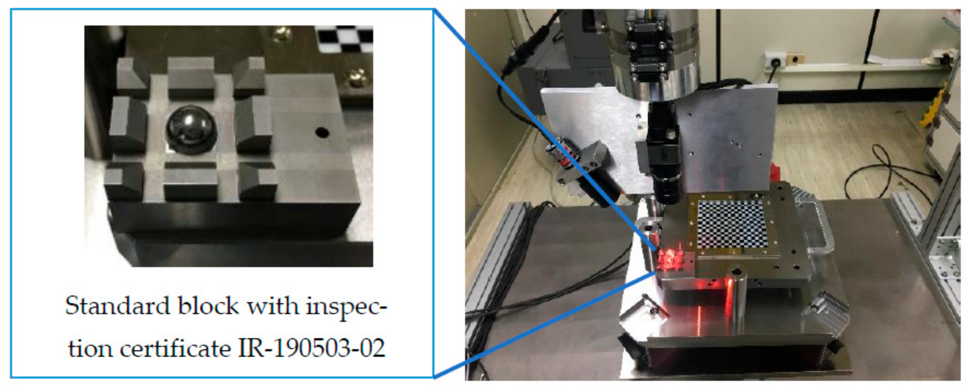
After the calibration is completed, the accuracy of the visual sensor also needs to be verified. A standard block with inspection certificate IR-190503-02 is designed, manufactured, and employed to verify the accuracy of the vision sensor. This verified standard block as shown in Figure 14 is placed on the calibration module to serve as the sensing object. The verification method is to visually detect the position of the standard block after moving and calculating the relative relationship between the robot arm and the standard block. The error between the calculated result and the actual value is the sensing accuracy error. The sensing module can calculate the relative relationship in real time after scanning. Figure 15 outlines the steps and show the actual test values of the accuracy of the visual sensor. For instance, when the standard block moves 1.0 mm, the position measured by the vision module is 1.04 mm. That is, an error of 0.04 mm is obtained from the calibration calculation. For the present engineering application, the allowable accuracy is 0.1 mm. From the test data, it was confirmed that the accuracy error after calibration is well below the targeted specification.
3.3. Hemming Experiment and Results
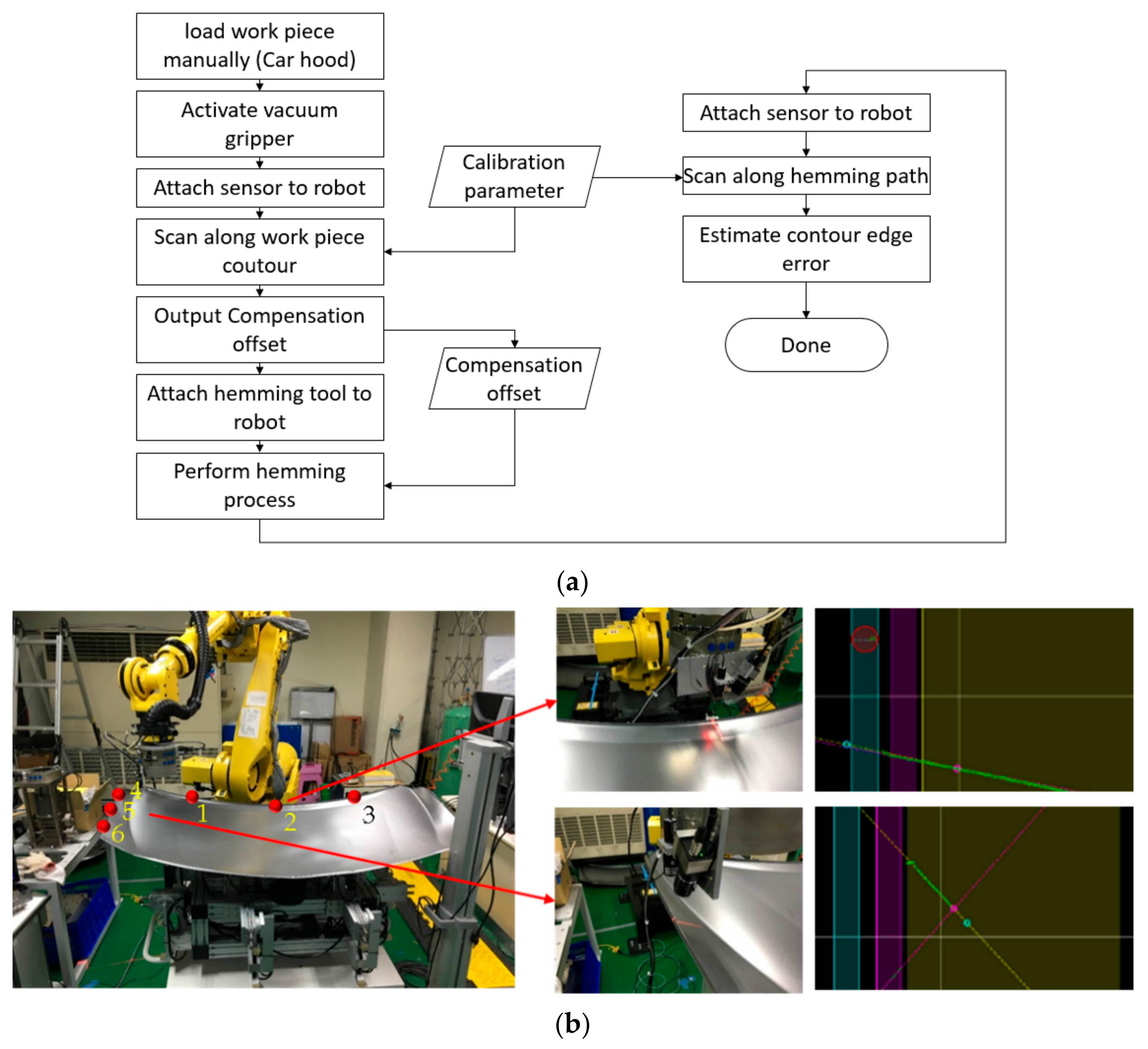
In order to understand how much positional deviation of the sheet metal work piece exists without a specific die, experiments using three car hood sheet metal parts of the same model were conducted. In each test, as illustrated in Figure 16, the sheet metal part was uploaded, aligned, and fixed on the universal platform, followed by manipulation of the robot arm to allow for the sensing module to scan three positions on the two edges of the sheet metal. Positions and orientations of the six points, as shown in Figure 16, were measured and are listed in the “Robot Pose” columns in Table 1. Here, X, Y, and Z are the absolute positions of the robot’s sensor frame with respect to the world frame and W, P, and R are the sensor frame’s orientation values. These measured values were used to estimate the hemming positions of the car hood sheet metal parts, that is Part A, B, and C as indicated in Table 1. Through this estimation, the desired sheet metal hemming positions were obtained, thereby the deformation and displacement of the sheet metal could be estimated. Through this experimental investigation, the position errors denoted as dX, dY, and dZ from Parts A, B, and C, respectively, were derived, and each of them corresponded to the maximum offset among Parts A, B, and C of the car hood along its Cartesian axis. The displacement offset error, the distance error ε in Table 1, is defined as the square root of the sum of squared dX, dY, and dZ. It is observed from the experiment that the offset error was found to be up to 3.695 mm, and the distance error ε was up to 4.461 mm, both of which far exceed the general sheet metal tolerance requirement of within 0.5 mm when fixed or when a specific die was used to support the sheet metal parts. On the other hand, should such offsets and distance errors be well controlled, they can be treated as calibration information for error compensation. The scanned data and the derived accuracy errors, namely the displacement offset and the distance error, for each of the car hood sheet metal parts are tabulated in Table 1.
For visualization of real-time compensation of the hemming path, relevant software has been developed, and a screenshot of the software is shown in Figure 17. In this software, the 3D surface reconstruction and position correction functions of the sheet metal are based on random sample consensus (RANSAC) [15], in which iterative closest points (ICP) [16] are used for point cloud features. The algorithm is adopted to match the reconstructed 3D surface of the sheet metal with the point cloud of the CAD model as a position correction.
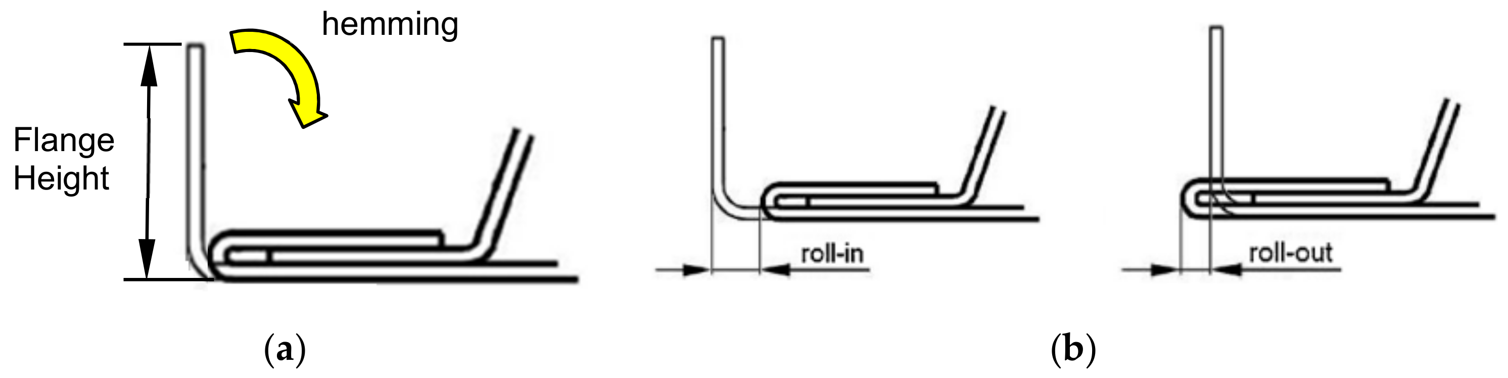
To demonstrate how the hemming process is performed, two 180 mm wide, 0.8 mm thick galvanized steel (SS41) flat metal sheets with either a 9 mm or 10 mm flange height were used for the hemming test as schematically illustrated in Figure 18a. With the previously described calibration process, the robot follows the path generated by the proposed visual path guidance model to perform hemming of these two flat steel sheets. The flange is progressively hemmed from to and then from to finally , during which process the upper rollers with different taper angles, as shown in Figure 2b, are interchanged.
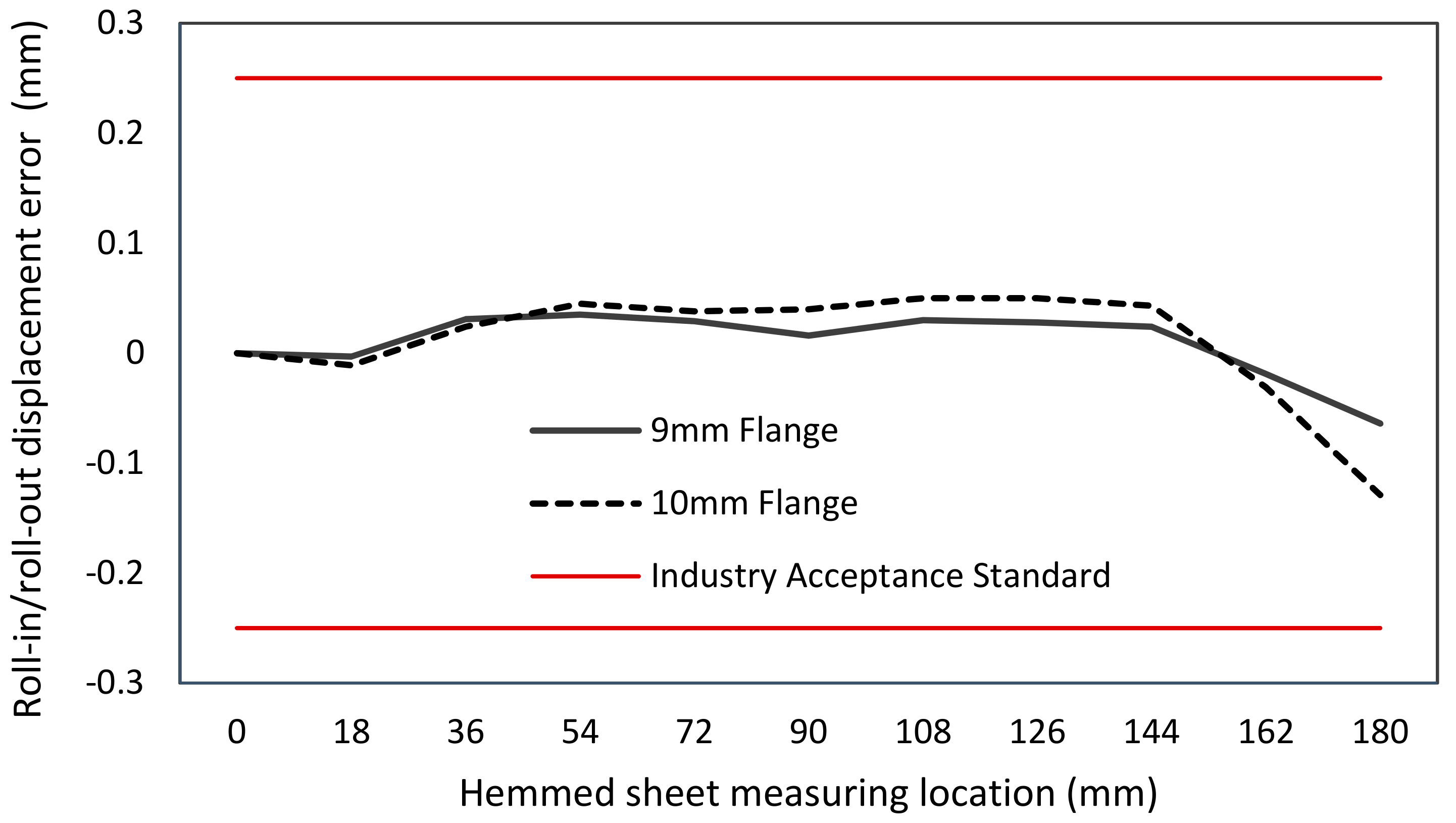
After the flange was hemmed, measurements of the roll-in/roll-out displacement error and the surface flatness, which are the two key measures of concern in the automobile industry, were conducted. The definition of the roll-in/roll-out displacement error is best illustrated in Figure 18b. As shown in Figure 18b, this displacement error is positive when the hemmed sheet’s contour edge is left off or out of the original vertical flange. On the other hand, the roll-in error gives a negative value as the hemmed sheet’s contour edge is in the right-hand side or inside the region where the original vertical flange was being hemmed to. In engineering practice, to ensure the hemmed sheet metal plate will provide suitable force onto the inner sheet metal, this roll-in/roll-out displacement error actually is the key design factor when sheet metal parts are connected through the hemming process. The roll-in/roll-out displacement error of the 9 mm and 10 mm flange height steel sheets after the hemming process are plotted in Figure 19, where the measuring location is along the hemmed part’s out-of-the-plane direction in Figure 18. With the proposed vision-based path guidance and the calibration method, one can observe that the roll-in/roll-out displacement errors are well within the ±0.25 mm specification (red lines) set by industry acceptance standards. The error becomes a little bigger around 170–180 mm, probably caused by the unbalanced force between the roller and the metal sheet when the robot reached the end of the 180 mm wide metal sheet.
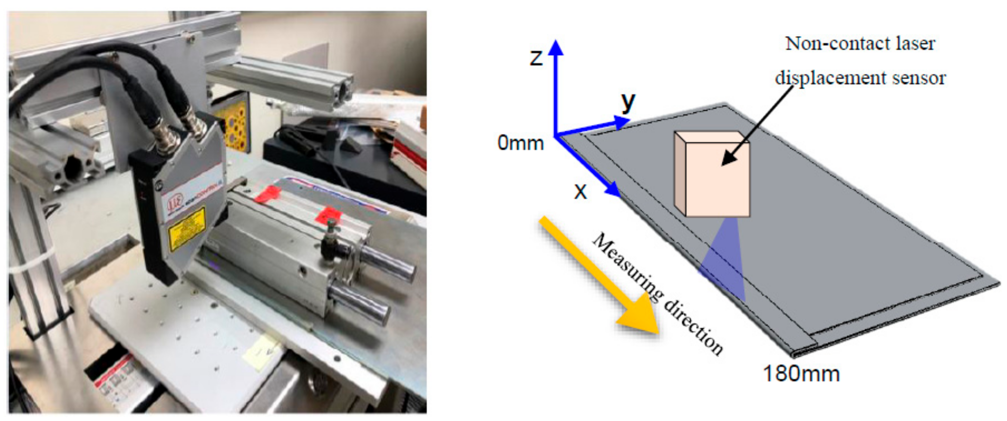
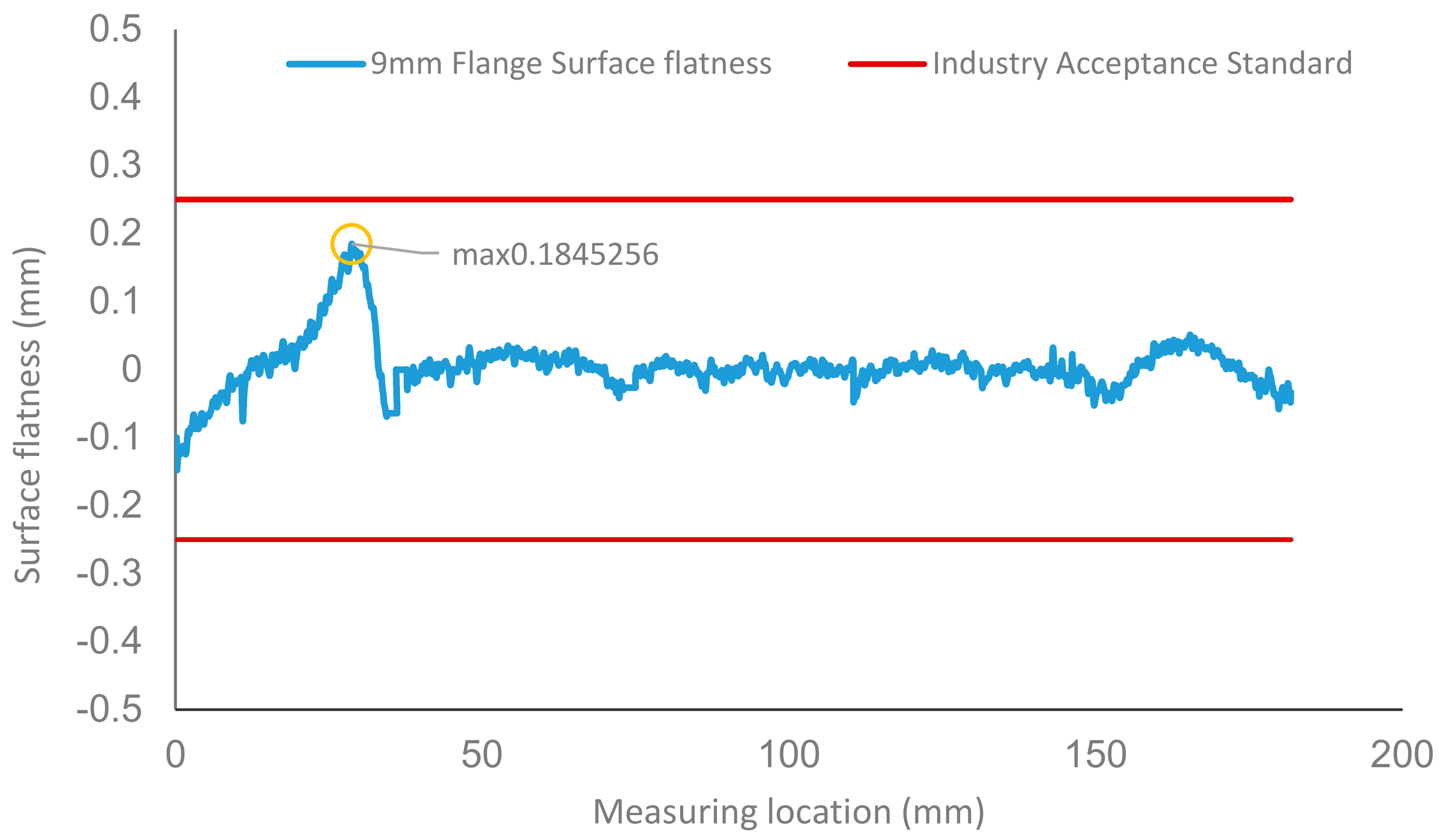
For the surface flatness measurement, as show in Figure 20, a non-contact laser displacement sensor, the Micro-Epsilon scan CONTROL 2900-10/BL, with out-of-plane accuracy of 0.02 mm was used to scan along the x-axis of the sheet at intervals of 0.05 mm. Results of surface flatness of the hemmed edge surface from the 9 mm flange height flat sheet metal through the forward hemming is shown in Figure 21. It is observed that the surface flatness of the hemmed sheet is well below the industry acceptance standard of ±0.25 mm. The maxima surface flatness of the sheet, being not very flat, is in the starting location when the hemming process takes place. Such non-flatness can be eliminated when the robot is undertaking backward hemming after forward hemming is completed. In general, the surface flatness of the hemmed sheets can be below ±0.05 mm by using the proposed method and system.
4. Conclusions
In the present industry application of robotic hemming, the sheet metal part is commonly supported by a large and bulky die to minimize positioning errors of the sheet metal part in the hemming process. Such positioning errors have been found to be the primary errors contributed by the robot arm when loading the part onto the die before the hemming process. Such errors are determined by robot arm’s accuracy and can be controlled within 0.1 mm, which is certainly below the industry requirement of 0.5 mm for hemming. To increase productivity and to allow small-volume large-variety production, dies-free robot hemming is thought to be the next manufacturing method in hemming sheet metal parts. As shown in Section 3.3 in this paper, without the support die to define and minimize the positioning error, errors of up to 4.4 mm can easily be found if the hemming path is generated solely from the CAD model, which does not meet the industry requirement.
To overcome the problem and to fill the technology gap, the work presented in this paper proposed a vision-guided positioning method to optimize the hemming path for the robot arm on the sheet metal part. Design of the quick-change sensor module and the hemming tool with an active double roller module were proposed, investigated, and validated in this research. As no clear data can be found in the dies-free robot roller hemming, a hand–eye calibration method was proposed for the robotic system to eliminate all the possible tolerances and position and orientation errors from the robot arm, the sensor module, the hemming tool, and the sheet metal part of the dies-free support. The proposed methods and system described in this paper were carefully validated through calibrated experiments with actual sheet metal parts. It was found that a single-axis error can be down to less than 0.1 mm with the proposed methods and system. The studies also indicate that the roll-in/roll-out error and surface flatness of the hemmed metal sheet are well below 0.2 mm, satisfying the industry acceptance standard of 0.5 mm. Through the investigation presented in this paper, it was concluded that a dies-free robotic hemming process can be achieved and is feasible with the proposed methods and system. The quick-change sensor module not only can provide critical information for hemming path compensation, but it can also be used to provide online measurement to ensure quality of the hemmed parts.
The work presented in this paper has archival values for research and development of dies-free robotic hemming. From the methods and system described and the reported results, one can further investigate topics such as active hemming tools that are more flexible yet automatically controllable and verifications and limitations of the dies-free roller hemming on complex curved surface sheet metal parts.
Author Contributions
Conceptualization, Y.-P.H. and B.-T.J.; methodology, Y.-P.H. and B.-T.J.; software, B.-T.J.; validation, Y.-P.H., B.-T.J., and C.-H.W.; formal analysis, Y.-P.H., B.-T.J., and C.-H.W..; investigation, Y.-P.H. and B.-T.J.; resources, Y.-P.H.; data curation, B.-T.J. and C.-H.W.; writing—original draft preparation, Y.-P.H.; writing—review and editing, Y.-P.H. and B.-T.J.; visualization, Y.-P.H.; supervision, J.-Y.C.; project administration, Y.-P.H. All authors have read and agreed to the published version of the manuscript.
Funding
This research was funded by Industrial Technology Research Institute (ITRI) with grant # K301AR3200.
Institutional Review Board Statement
Not applicable.
Informed Consent Statement
Not applicable.
Data Availability Statement
Not applicable.
Conflicts of Interest
The authors declare no conflict of interest.
References
- Maeno, T.; Mori, K.; Sakagami, M.; Nakao, Y.; Talebi-Anaraki, A. Minimisation of heating time for full hardening in hot stamping using direct resistance heating. J. Manuf. Mater. Process. 2020, 4, 80. [Google Scholar] [CrossRef]
- Talebi-Anaraki, A.; Chougan, M.; Loh-Mousavi, M.; Maeno, T. Hot gas forming of aluminum alloy tubes using flame heating. J. Manuf. Mater. Process. 2020, 4, 56. [Google Scholar] [CrossRef]
- Talebi-Anaraki, A.; Maeno, T.; Ikeda, R.; Morishita, K.; Mori, K. Quenchability improvement and control simplification by ice mandrel in hot stamping of ultra-high strength steel hollow parts. J. Manuf. Process. 2021, 64, 916–926. [Google Scholar] [CrossRef]
- Thuillier, S.; Le Maoût, N.; Manach, P.Y.; Debois, D. Numerical simulation of the roll hemming process. J. Mater. Process. Technol. 2008, 198, 226–233. [Google Scholar] [CrossRef]
- Arroyo, A.; Pérez, I.; Gutierrez, M.; Bahillo, J.; Toja, H. Roller hemming: A new simulation model for the automotive industry. In Proceedings of the 36th International MATADOR Conference, London, UK, 14–16 July 2010; pp. 83–86. [Google Scholar]
- Hu, X.; Zhao, Y.; Huang, S.; Li, S.; Lin, Z. Numerical analysis of the roller hemming process. Int. J. Adv. Manuf. Technol. 2012, 62, 543–550. [Google Scholar] [CrossRef]
- Gürgen, S. A parametric investigation of roller hemming operation on a curved edge part. Arch. Civ. Mech. Eng. 2019, 19, 11–19. [Google Scholar] [CrossRef]
- Jimbert, P.; Perez, I.; Eguia, I.; Daehn, G.S. Straight hemming of aluminum sheet panels using the electromagnetic forming technology: First approach. Key Eng. Mater. 2007, 344, 365–372. [Google Scholar] [CrossRef]
- Kleeh, T.; Merklein, M.; Roll, K. Modeling laser heating for roller hemming applications. Key Eng. Mater. 2011, 473, 501–508. [Google Scholar] [CrossRef]
- Kleeh, T.; Merklein, M.; Roll, K. Laser heat treatment effects on roller hemming in aluminum alloys. Key Eng. Mater. 2012, 504–506, 711–716. [Google Scholar] [CrossRef]
- Dewang, Y.; Sharma, V. A study on sheet metal hemming process. Mater. Today Proc. 2020, 27, 2091–2095. [Google Scholar] [CrossRef]
- Świłło, S. Experimental apparatus for sheet metal hemming analysis. Comp. Mater. Sci. 2013, 13, 326–332. [Google Scholar]
- Hang, Z.; Zhang, L.; Yang, G.Z. A computationally efficient method for hand–eye calibration. Int. J. Comput. Assist. Radiol. Surg. 2017, 12, 1775–1787. [Google Scholar]
- Koide, K.; Menegatti, E. General hand–eye calibration based on reprojection error minimization. IEEE Robot. Autom. Lett. 2019, 4, 1021–1028. [Google Scholar] [CrossRef]
- Fischler, M.A.; Bolles, R.C. Random sample consensus: A paradigm for model fitting with applications to image analysis and automated cartography. Commun. ACM 1981, 24, 381–395. [Google Scholar] [CrossRef]
- Besl, P.J.; McKay, N.D. A method for registration of 3-D shapes. IEEE Trans. Pattern Anal. Mach. Intell. 1992, 14, 239–256. [Google Scholar] [CrossRef]
Figure 1.
A universal fixed platform for a hemming process: (a) front view; (b) enlarged view of upper part.
Figure 1.
A universal fixed platform for a hemming process: (a) front view; (b) enlarged view of upper part.

Figure 2.
The hemming tool: (a) the traditional single roller; (b) an active double-roller with different shapes of upper rollers.
Figure 2.
The hemming tool: (a) the traditional single roller; (b) an active double-roller with different shapes of upper rollers.

Figure 3.
The design of the proposed quick-change sensor module: (a) schematic illustration; (b) photograph of the module on a robot arm.
Figure 3.
The design of the proposed quick-change sensor module: (a) schematic illustration; (b) photograph of the module on a robot arm.

Figure 4.
Schematic illustration of the quick-change sensor module and the quick-change interface.

Figure 5.
Schematic drawing of the hand–eye coordinate system and location of the sensor frame.

Figure 6.
Hand–eye conversion calculation process.

Figure 7.
The calibration procedure.

Figure 8.
(a) A schematic drawing and (b) photograph showing the hand–eye calibration device used in this study.
Figure 8.
(a) A schematic drawing and (b) photograph showing the hand–eye calibration device used in this study.

Figure 9.
Photographs showing the calibration procedure by manipulating the robot to calibrate (a) the tool center point (TCP) with different postures and (b) the world frame with the same posture.
Figure 9.
Photographs showing the calibration procedure by manipulating the robot to calibrate (a) the tool center point (TCP) with different postures and (b) the world frame with the same posture.

Figure 10.
Photographs showing the (a) robot arm reference point calibration with the reference ball and (b) hand–eye relationship calibration with the optic calibration plate.
Figure 10.
Photographs showing the (a) robot arm reference point calibration with the reference ball and (b) hand–eye relationship calibration with the optic calibration plate.

Figure 11.
Illustrated example of estimating the actual hemming point.

Figure 12.
The optic calibration plate and reference ball coordinate measurement results.

Figure 13.
The calibration data displayed by the self-developed hand–eye relationship calibration software.
Figure 13.
The calibration data displayed by the self-developed hand–eye relationship calibration software.

Figure 14.
The verified standard block and its location on the calibration module.

Figure 15.
Steps for the verification and values of the accuracy of the visual sensor.

Figure 16.
Workflow (a) and photographs illustrating the manipulation of the robot arm for the sensing module to capture positions and orientations at the six points of the car hood sheet metal (b).
Figure 16.
Workflow (a) and photographs illustrating the manipulation of the robot arm for the sensing module to capture positions and orientations at the six points of the car hood sheet metal (b).

Figure 17.
Screenshoot of the software to visualize the real-time compensation path for hemming.

Figure 18.
Schematic drawings showing (a) the sheet metal hemming experiment and (b) the definition of the contour edge roll-in/roll-out displacement error.
Figure 18.
Schematic drawings showing (a) the sheet metal hemming experiment and (b) the definition of the contour edge roll-in/roll-out displacement error.

Figure 19.
Measured roll-in/roll-out displacement error of after being hemmed.

Figure 20.
Photography and schematics for surface flatness measurement of the hemmed edge.

Figure 21.
Measured surface flatness of the hemmed edge.


Table 1.
The scanned data and errors of the car hood sheet metal parts.
| Unit: mm | |||||||||||
|---|---|---|---|---|---|---|---|---|---|---|---|
| Robot Pose | Part A | Part B | Part C | XYZ Offset among 3 Parts | Distance Error ε | ||||||
| P1 | X | 1215.305 | W | −179.887 | X | −10.073 | −8.826 | −7.456 | dX | 2.617 | 3.017 |
| Y | −393.498 | P | −0.474 | Y | 0.222 | 0.220 | 0.220 | dY | 0.002 | ||
| Z | 589.524 | R | −9.634 | Z | −4.278 | −4.517 | −5.780 | dZ | 1.502 | ||
| P2 | X | 1300.716 | W | −179.886 | X | −9.779 | −8.975 | −7.712 | dX | 2.067 | 2.729 |
| Y | 103.561 | P | −0.473 | Y | 0.222 | 0.220 | 0.212 | dY | 0.010 | ||
| Z | 550.759 | R | 20.929 | Z | −4.396 | −4.379 | −2.614 | dZ | 1.782 | ||
| P3 | X | 1275.583 | W | −179.887 | X | −10.160 | −9.843 | −9.186 | dX | 0.974 | 2.171 |
| Y | −451.610 | P | 0.475 | Y | 0.219 | 0.219 | 0.222 | dY | 0.003 | ||
| Z | 568.554 | R | 32.942 | Z | −3.095 | −3.594 | −5.035 | dZ | 1.940 | ||
| P4 | X | 1377.169 | W | −179.888 | X | 0.177 | 0.178 | 0.183 | dX | 0.006 | 4.245 |
| Y | −560.232 | P | 0.473 | Y | −1.192 | −1.892 | −3.282 | dY | 2.090 | ||
| Z | 641.432 | R | −77.453 | Z | 2.664 | 1.646 | −1.031 | dZ | 3.695 | ||
| P5 | X | 1517.209 | W | −179.888 | X | 0.192 | 0.192 | 0.197 | dX | 0.005 | 4.461 |
| Y | −568.234 | P | 0.473 | Y | −2.170 | −2.619 | −4.676 | dY | 2.506 | ||
| Z | 641.432 | R | −76.687 | Z | −3.375 | −3.734 | −7.066 | dZ | 3.691 | ||
| P6 | X | 1659.402 | W | −179.888 | X | 0.191 | 0.191 | 0.197 | dX | 0.006 | 4.278 |
| Y | −565.426 | P | 0.473 | Y | −1.530 | −1.781 | −3.754 | dY | 2.224 | ||
| Z | 627.715 | R | −73.193 | Z | −2.539 | −2.678 | −6.193 | dZ | 3.654 | ||
Publisher’s Note: MDPI stays neutral with regard to jurisdictional claims in published maps and institutional affiliations. |
© 2021 by the authors. Licensee MDPI, Basel, Switzerland. This article is an open access article distributed under the terms and conditions of the Creative Commons Attribution (CC BY) license (https://creativecommons.org/licenses/by/4.0/).
Share and Cite
MDPI and ACS Style
Huang, Y.-P.; Jiang, B.-T.; Wu, C.-H.; Chang, J.-Y. Vision-Based Path Guidance to Achieve Dies-Free Roller Hemming Process. Appl. Sci. 2021, 11, 5741. https://0-doi-org.brum.beds.ac.uk/10.3390/app11125741
AMA Style
Huang Y-P, Jiang B-T, Wu C-H, Chang J-Y. Vision-Based Path Guidance to Achieve Dies-Free Roller Hemming Process. Applied Sciences. 2021; 11(12):5741. https://0-doi-org.brum.beds.ac.uk/10.3390/app11125741
Chicago/Turabian StyleHuang, Yi-Ping, Bor-Tung Jiang, Chia-Hung Wu, and Jen-Yuan Chang. 2021. "Vision-Based Path Guidance to Achieve Dies-Free Roller Hemming Process" Applied Sciences 11, no. 12: 5741. https://0-doi-org.brum.beds.ac.uk/10.3390/app11125741
Note that from the first issue of 2016, this journal uses article numbers instead of page numbers. See further details here.