
A Wireless Hand Grip Device for Motion and Force Analysis
by
 , and
, and
Victor Becerra
1, 
Francisco J. Perales
2,*,
Miquel Roca
3,
José M. Buades
2 and
Margaret Miró-Julià
2 1
Ilunion, E-28527 Madrid, Spain
2
Mathematics and Computer Science Department, Universitat de les Illes Balears, E-07122 Palma, Spain
3
Industrial Engineering and Construction Department, Electronic Technology, Universitat de les Illes Balears, E-07122 Palma, Spain
*
Author to whom correspondence should be addressed.
Appl. Sci. 2021, 11(13), 6036; https://0-doi-org.brum.beds.ac.uk/10.3390/app11136036
Submission received: 5 May 2021
/
Revised: 23 June 2021
/
Accepted: 24 June 2021
/
Published: 29 June 2021
(This article belongs to the Topic Extended Reality (XR): AR, VR, MR and Beyond)
Abstract
:A prototype portable device that allows for simultaneous hand and fingers motion and precise force measurements has been. Wireless microelectromechanical systems based on inertial and force sensors are suitable for tracking bodily measurements. In particular, they can be used for hand interaction with computer applications. Our interest is to design a multimodal wireless hand grip device that measures and evaluates this activity for ludic or medical rehabilitation purposes. The accuracy and reliability of the proposed device has been evaluated against two different commercial dynamometers (Takei model 5101 TKK, Constant 14192-709E). We introduce a testing application to provide visual feedback of all device signals. The combination of interaction forces and movements makes it possible to simulate the dynamic characteristics of the handling of a virtual object by fingers and palm in rehabilitation applications or some serious games. The combination of these above mentioned technologies and open and portable software are very useful in the design of applications for assistance and rehabilitation purposes that is the main objective of the device.
1. Introduction
Currently, new paradigms of natural interactions with computer are explored. One of the most used is hand gestures as control input in Human–Computer Interaction (HCI) [1,2]. Hand movements are a means of non-verbal communication and can take the form of either simple actions or more complex ones. Therefore, it stands to reason that using the hands can be an intuitive method for communication with computers [1,2]. New Virtual Reality [3] systems need, not only information about hand position, but also force values from the controlled input device. There is a need for kinematic and kinetic information in real time. Additionally, the combination of these above mentioned technologies are very useful in design applications for assistance and rehabilitation purposes, which is our main objective.
Hands can be considered as a complex biomechanical structure with a high number of degrees of freedom (DOF) [4]. Therefore, it should be possible to use the hands as a high DOF control device in a wide range of applications (ludic or medical) [1,2,3,4]. Two major types of technology for HCI can be identified, namely contact-based and vision-based devices. Contact-based devices (CBD) rely on physical interaction with the user. On the other hand, vision-based devices (VBD) analyze one or more video streams for determining hand motions. VBD technology can measure the motion of the end-effectors (fingers and the whole hand), but not the force done to catch an object. A large number of contact-based data gloves have been developed over the last thirty years [5], whereas vision-based tracking of the hands has been in development for about two decades [6]. We are aware of the complex challenges in hand gesture vision recognition and also of their limitations. Thus, we are more oriented to consider new low-cost contact-based systems, less invasive than the traditional gloves. Furthermore, the CBD can fill in the data gap that occurs with VBD during camera occlusions.
An interesting subset of CBD is the wireless microelectromechanical based sensors (WMES). These systems use a set of interconnected sensors for motion and force measurements. Different aspects of fingers and hand motion are considered, and the combined data is used for higher-level feature extraction in gesture recognition and force performance [7].
To our knowledge, very few low-cost, wireless systems for hand tracking and force measurement are proposed in the literature. In [8], an interesting system to evaluate upper link task in Parkinson disease is proposed. This system considers a low-cost RGB-Depth camera using a monitor for visual feedback of the hand movements of the patient. The user’s equipment is a pair of black silk gloves with imprinted color markers, which are used for the gestural control of the system and for task assessments. In the paper, a comparison between the offered solution and consumer devices is provided. In a precise qualitative evaluation, the system has been compared favorably with popular consumer alternatives. If we consider the system as a VBD, the forces done by the end user cannot be measured.
A study using a data fusion approach is presented in [9]. The system combines the Nimble VR vision-based system, using the Kinect camera, with the contact based 5DT Data Glove. This is an approach that uses the fusion of vision and contact, increasing the data completeness, and thus providing substantial advantage over the sole use of one device. In this system, the hands are detected using infrared depth information obtained from the Kinect camera. Using a previous hand’s skeletal model, an estimation of the orientation and position of the hand and fingers is calculated. The 5DT Data Glove was added to this setup, allowing for a double validation of the system. In the first method, a wooden articulated manikin hand model hand was used. The second method used dynamic hand movements with three human hands of different sizes to assess the robustness of the Kalman filter output. From the results observed in the paper, the application of the Kalman filter for fusing vision-based data with contact-based tracking data provided substantial improvements in precision and to a lesser extent improvement in accuracy. This method allows the system to mitigate the visual self-occlusion of the fingers and data completeness is obtained. On the other hand, the system is a little bit invasive and unable to measure the force done by hand and fingers.
Another Data Glove approach is presented in [10]. The main idea is to obtain an accurate measurement of thumb carpometacarpal (CMC). The CMC-joint movement is still a challenge due to crosstalk between the multi-sensor outputs required to measure the degrees of freedom. In order to properly measure CMC-joint configurations, sensor locations that minimize sensor crosstalk must be identified. This work presents a novel approach in identifying optimal sensor locations. Although the proposed method improves the accuracy of the sensing system, from the pictures provided we can conclude that it is very invasive and user’s preparation time can be very high.
The research ideas most similar to our proposal are considered in [11]. A full evaluation of motor task performance during grasp movements requires, besides kinematic, also kinetic measures. An emerging microelectromechanical system (MEMS) for HCI purposes is proposed. The instrumentation setup consists of 3D accelerometers and gyroscopes embodied in a single chip (ST LSM330DLC), which are distributed along the dorsal side of the hand. The system attached to the hand is robust, flexible and low-cost. The system’s evaluation is done measuring kinematic and kinetic sensor data simultaneously, applying orientation filters and subsequently applying a recursive system identification algorithm. The system offers an approach for measuring pressure sensing and gesture recognition in a combined manner. This solution opens the ability to gather profound insights into interaction optimization between the human body and its environment, in particular for VR applications. Another interesting and novel haptic exoskeleton device is presented in [12]. The device can measure the user’s hand motion and assist hand motion while remaining portable and lightweight. The device consists in a five-finger mechanism actuated with miniature DC motors through antagonistically routed cables at each finger, which act as both active and passive force actuators. The glove can be wirelessly linked to a computer for displaying and recording the hand status through 3D Graphical User Interface (GUI) in real-time. A positive aspect of this system is its portability (wireless) and its adaptability to a wide variety of finger sizes. The user’s fatigue is low, the system is inexpensive, and over one hour of continuous operation is reached without the need for recharging. Unfortunately, this version of the glove does not include an inertial measurement unit and it is also highly invasive. The SAFE Glove needs mechanical refinement directed towards the use of smaller and stronger components to reduce bulkiness and improve comfort for the wearer.
Another important aspect to note is the advancement in the area of sensors and actuators. Papers [13,14,15] explore the advances in tactile sensing technologies. The three abovementioned papers show different surveys about various technologies and transduction methods. The work done in [16] shows a survey of hand exoskeleton technologies for rehabilitation and assistive engineering, from basic hand biomechanics to actuator technologies. The main requirements of these hand exoskeleton devices are also identified, and the mechanical designs of existing devices are classified. The paper is oriented to the world’s aging society and an increased demand for the practical application of assistance and rehabilitation technologies.
The low cost of the final device proposed for human motion and force measurement is an important factor in order to achieve future commercialization. In papers [17,18], the authors propose a cost-effective three-finger exoskeleton hand motion-capturing device [17] or a sensor glove with vibrotactile feedback and multiple finger joints and hand motion sensing [18]. The first device provides 12 DOFs data of finger motion by a unique bevel-gear structure as well as the use of six 3D magnetic sensors. The system enables feasibility of object manipulation as far as the needs go in various tasks in virtual environment. The second glove allows separate measurements of proximal and distal finger joint motions as well as position/orientation detection with an inertial measurement unit (IMU). These sensors and tactile feedback induced by coin vibration motors at the fingertips are integrated within a wireless, easy-to-use, and open-source system. The main advantages of this system are an easy-to-use and low-cost system with wireless connection to the host computer.
From a holistic point of view, we can analyze the human motion with multisensorial information. This perspective is proposed in [19]. The author presents a generalized framework integrating multiple modules: sensor integration, signal preprocessing, correlation study of sensory information, and motion identification. Three types of sensors are integrated to simultaneously capture the finger angle trajectories, the hand contact forces, and the forearm electromyography (EMG) signals. The paper shows accurate results and effective solutions for motion capturing, data synchronization and segmentation, correlation study of the sensory information, and motion recognition. The proposed framework integrates the state-of-the-art sensor technology, mature machine learning methods, and signal processing algorithms.
Along the same lines, Ref. [20] shows a complete review of multimodal human hand motion sensing and analysis. The work is current and includes the most recent data gloves available in the market. Additionally, clear figures and diagrams show all multimodal force-based and vision-based sensing information flow and signal processing.
The work done in [21] offers a new review on multimodal human hand motion sensing. In this novel paper, a summary of hand motion analysis methods, including contact and non-contact devices, is presented. Additionally, surface electromyography (EMG) is analyzed as a tool for evaluation of the biofeedback of muscle movements by measuring the EMG signal on the surface of the skin. In Ref. [22], another data glove solution for hand motion tracking and gesture recognition is proposed. The KHU-l data glove consists in three tri-axis accelerometer sensors, one controller, and one Bluetooth module. The system can send full information to the PC through wireless communication using Bluetooth. The implemented 3-D digital hand model is based on the kinematic chain theory utilizing ellipsoids and joints. Due to the sensor’s technical specification, we conclude that the system is highly intrusive. Furthermore, the number of hand gesture recognition possibilities are very limited (scissor, rock and paper). The system needs faster computation to reduce the time delay between actions recognition. The optoelectronic approach is an alternative for the evaluation of motor and cognitive capabilities. In Ref. [23], a method to capture motion of a pen through a mo-cap optoelectronic system was developed. Four IR passive markers were placed on a pen cap. Once a pen was equipped with the cap, track of tip was computed through a numeric algorithm using the 3D coordinates of markers provided by the optoelectronic system. The system is oriented to evaluate precisely the writing and drawing techniques on a tablet using this pen cap. The contribution is the new acquisition protocol using a new marker’s configuration of the system. In this situation, the marker was not placed on the pen but on a surmounting cap, in order to allow a free and as natural as possible grasp of the pen. This new solution allows for a very accurate reconstruction of the pen tip coordinates and had the advantage to be suitable for handwriting and movement acquisition for pathologic subjects. The system does not measure any force done by subject over the pen tip. Additionally, the system requires higher costs than a computerized tablet and a dedicated room with trained staff.
A hand tracking perspective based on magnets attached to fingers and an electronic wristband is presented in [24]. This system exploits advanced design of magnetic flux sensors and recent research on hand-based communication. It is wireless, portable, unobstructive and convenient. The proposed method considers two computational steps. The first step estimates the locations and orientations of the magnets and the fingertips from the measured flux densities; and the second step reconstructs the finger postures from the locations and orientations of the fingertips based on a geometric model of the fingers. The system is validated against a Vicom motion tracking system. In general, the estimation based on magnetic data was reasonably consistent with the direct measurement of the joint angles. Unfortunately, problems arise in the magnetic flux measurements when the system is operated near objects constructed of magnetic materials.
To present the most important contribution of wearable sensing gloves, we consider the work done in [25,26]. The first contribution presents a wearable sensing glove with embedded hetero-core fiber-optic nerve sensors that detect finger flexion to achieve unconstrained hand motion monitoring. The hetero-core fiber sensor is suited to the wearable sensing glove because it is capable of optical intensity-based measurements with excellent stability and repeatability using single-mode transmission fibers and is unaffected by temperature fluctuations. The system has been validated using a virtual reality application and the sensitivity and accuracy in the detected flexion angles are small. In paper [26], a data glove equipped with force sensors is presented. The force sensor is made of a steel plate substrate where the commercial strain gauges are attached. The plate is attached to the thumb. The system has a sensor calibrated to measure between 0 and 100 N, with a resolution of 0.38N and excellent repeatability. In any case, we consider that the system is obtrusive and needs direct connection to a PC.
All of the above presented systems include wearable sensors with applications in human biomechanical and health monitoring. In order to summarize the progress and challenges in fabrication of wearable sensors, recent work done in [27] was reviewed. A similar practical application using wearable thermal sensors was presented in [28].
In tune with the above mentioned state of the art, a summary of the main objectives and research contributions of this work follows below.
- (a).
- The proposed hand grip device uses sensors, not influencing natural hand and finger movements.
- (b).
- A wireless, portable and flexible prototype hand grip device that allows simultaneous hand and fingers precise motion and force measurements is presented.
- (c).
- The device design is oriented for its use in medical rehabilitation applications or serious games, but it is it can also be considered in ludic VR applications.
- (d).
- The software is plain and simple to use, and integrates easily in all platforms with standard communications protocols.
- (e).
- The cost of all electromechanical parts used in the device have been carefully analyzed in order to fit the final cost. In addition, hardware architecture is defined in such a way to easily incorporate extensions of new wearable sensors (EMG, EEG, Heart Rate, etc.).
The rest of the paper is organized as follows: first, the materials and methods of the system are described, along with the details of its HCI in Section 2. Next, in Section 3, the experimental setup for every device is detailed, and the main results presented including an exhaustive validation testing for 3D hand position tracking evaluation and force error evaluation against several commercial devices is presented. Finally, Section 4 summarizes the main contribution of our proposed device and future improvements.
2. Materials and Methods
In this section, the main requirement of the system’s design is introduced and the different electronic devices and their layout are described. The minimum requirements or functionalities that the wireless hand device needs to satisfy in order to be useful as a rehabilitation system are proposed. These main requirements are:
- Gauges or linear potentiometers to obtain the magnitude of the hand’s force;
- Accelerometer and Gyroscope (9DOF) to obtain device’s 3D position and orientation;
- Resistive pressure sensors FSR for the fingers;
- Self-contained device with incorporation of batteries;
- A PIC to convert the A/D data and send it by RF to the PC;
- Wireless communication, RF module (Bluetooth).
Considering the previous functional requirements and taking into account portability and low-cost, we opted for items with the following mechanical properties: tensile strength and sufficient compression to withstand the grip force exerted by the hand without deforming or breaking apart. For all these reasons, the material used was polyvinyl chloride (PVC).
The device has two blocks. The first block contains all electronic components, such as, sensors, battery, microcontroller and the communication module. This block is subdivided in three parts: the main body and two covers, the block was put together using 4 screws in each cover. The second block is responsible for transmitting the force exerted by the hand to the two force sensors. This block is attached to the main body with 4 screws; sufficient clearance is provided as to not affect the force measurements. Additionally, the central part of the main body is reinforced using a 4 mm × 140 mm aluminum sheet. Three-dimensional shaders of the prototype are shown below in Figure 1.
The original PVC block was milled using an industrial CNC Odisea milling machine and all data and coordinates was introduced using the machine’s front panel. In the case of commercial industrial production, a mechanical design using plastic injection will be considered in order to decrease final costs.
2.1. Hardware Implementation
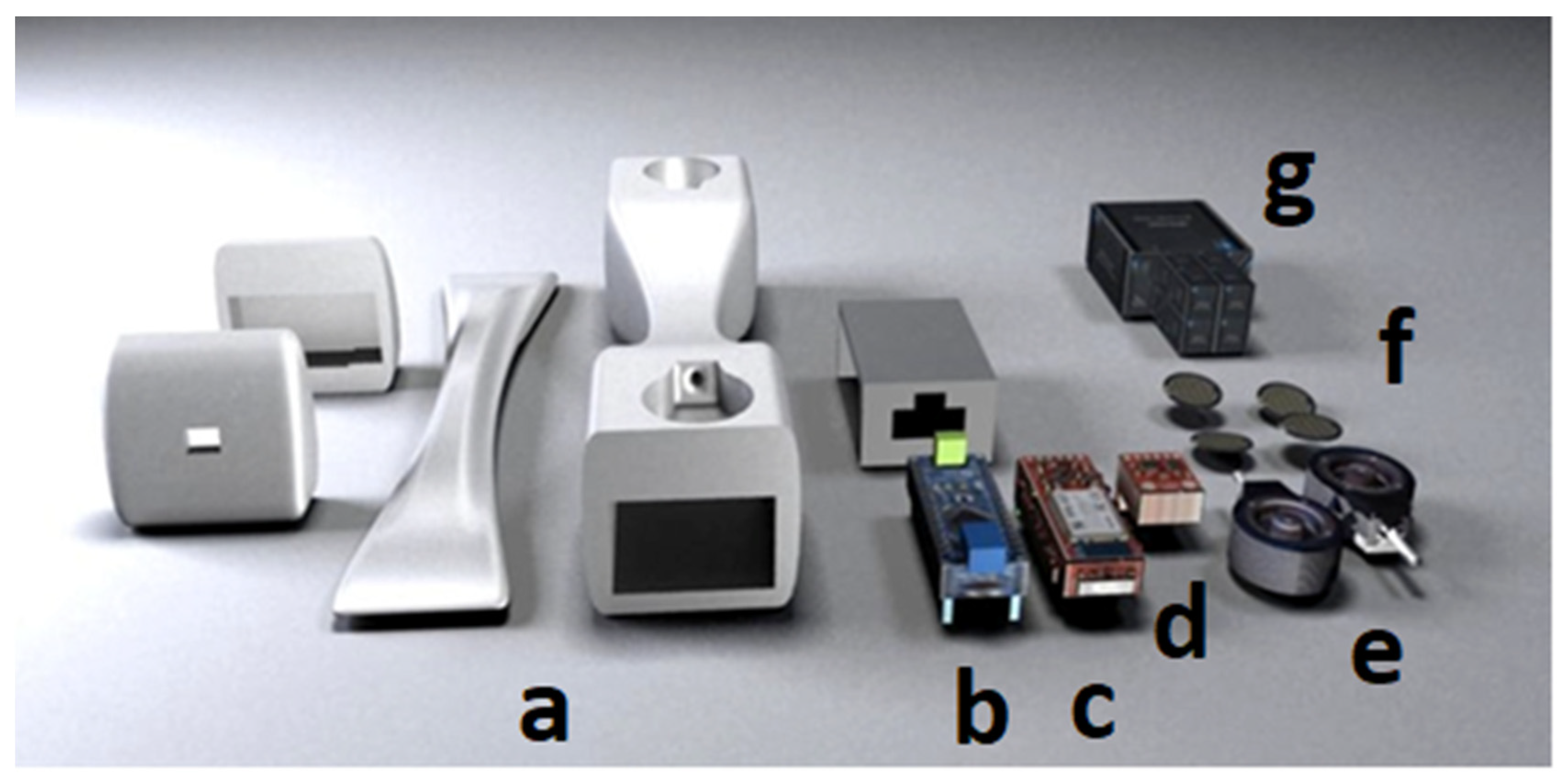
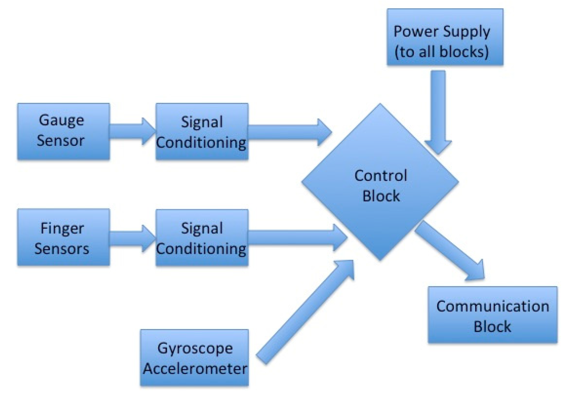
Figure 2 depicts the hardware components of the device, which are briefly described below.
- Power of the system: This part includes a battery that provides a 3V voltage, which is converted to 5V through a DC/DC regulator.
- Sensors: This block contains a gauge that measures the force made by the user’s hand; four sensors are able to detect the pressure of the fingers; a gyroscope and an accelerometer measures hand movements (velocity and acceleration) in order to detect user’s tremors.
- Control of the system: A microcontroller circuit is in charge of controlling the system. This circuit presents A/D converters at some inputs, and then analog inputs are presented to the microcontroller. These inputs are necessary since the output of some of the considered sensors is analog and they must be processed by the full system.
- Communications block: The hardware also includes a RF circuit that is able to communicate with a laptop. This feature allows data presentation on the laptop’s screen. It is a desirable element in the design of games with ludic or rehabilitation therapy objectives.
One of the most important sensors is dedicated to the measurement of the force that is applied by the user’s hand. In this prototype, a force cell based on a Wheatstone bridge composed by four gauges has been considered. In particular, two identical cells are placed at both ends of the device. Each cell is capable of measuring a force up to 45.35 kg, thus the total force is the sum of the forces applied two both cells, that is 90.7 kg.
Based on experimental studies performed in [29,30,31,32] that show the development of a normative data table for hand grip and pinch strength and a summary of grip strength measurements obtained recently, we propose several electromechanically devices that allow the capture of hand motion and force. We also propose a comparative evaluation of our solution against the commercial dynamometer used in [32]. Another important contribution is related to the ergonomically evaluation of biomechanical hand function presented in [33]. Ref. [34] presents a review of the measurement of grip strength in clinical and epidemiological studies, whereas this paper proposes a standardized method for a more consistent grip strength measurement.
These cells give us an output of 16–24 mV depending on the applied force. An instrumentation amplifier (AD627) is used for signal conditioning to obtain a voltage range compatible with the control block (analog inputs of the microcontroller). This instrumentation amplifier is rail-to-rail, presents a low consumption (85 microamperes), and the gain can be controlled by using a resistor between pins 1 and 8 of the chip. The response time is 135 microseconds. All these features are adequate and comply with the device requirements. Figure 3 shows a picture of the sensor used.
Another component of the sensor block is dedicated to the detection of hand movement. In this part, an inertial measurement unit (IMU), which includes a gyroscope (ITG-3200 model) and an accelerometer (ADXL345 model), has been considered. This unit, produced by SparkFun Corporation, allows for six measurements (Roll, Pitch, Yaw, X, Y, Z). With this data, we can estimate the movements of the hand in terms of position, velocity and acceleration. This information is very important in the detection of tremors. The two chips (accelerometer and gyroscope) are placed on a PCB with reduced dimensions and incorporated to the device. The communication between these sensors and the control block is done through I2C protocol. The last set of sensors is resistive force sensors. These sensors control the adequate positioning of the fingers. In this case, a high precision sensor is not necessary. The use of these sensors, based on a polymer film (PTF) that shows a reduction of its resistance value when a force is applied, is acceptable. For ludic applications of the device, only finger position will be required; for therapeutic applications, the system would also detect changes in the force generated by the patient. These force sensors are connected to the inputs of the control block in a pull up configuration, where each sensor is connected between the power supply and a 10K grounded resistor. A good comparative study of the performance evaluation of five commercially available low-cost piezo resistive sensors with potential application in compression therapy is provided in [35].
The microcontroller considered in the control block is the ATmega328. A PCB Arduino Nano, which contains the ATmega328 microcontroller, has been used. This platform has 8 analog inputs, which are enough to read the voltage values of the analog outputs of sensors.
The communication between the microcontroller and the computer is done at two levels:
- USB: This option is only used to upload the software into the Arduino Nano PCB. Once the program is loaded, this communication is no longer needed. This communication is not necessary when the device is performing ludic or therapeutic tasks since it works as a real wireless device. The device’s application will be defined in the program design. In general, the microcontroller will read data from the different sensors and, depending on the data, will perform different actions. These actions include data visualization, data storage, data analysis or its interaction with ludic or therapeutic games.
- RF communication: This is a new part of the device complying with the communication block mentioned above. It is composed by a BlueSMIRF Silver V2 Bluetooth wireless modem by SparkFun Corporation. The communication range is 18 m, good enough for the specifications of the device. The modem is placed on a PCB with reduced dimensions that could be integrated inside the device.
The last part of the hardware is the power supply. Considering the wireless requirement of the device, the main element of the power supply is a battery. We have considered a rechargeable 3.75V ion-lithium battery with a capacity of 2.2 Ah. The rechargeable circuit is the MAX1811 integrated circuit, which is compatible with the battery used and can be charged via USB connection. The dimensions of the battery are 69 mm × 21 mm × 18.5 mm, and its weigh is 55g. All the circuits are biased between 0–5 V (note that the instrumentation amplifier is a rail-to-rail 0–5 V), and this facilitates the power supply implementation. The last component of the power supply is a DC/DC converter, which converts the 3.75 V of the battery to 5 V. The MAXIM683 chip is considered. This circuit is based on a charge pump, has a yield of 85%, a fixed output voltage of 5 V and a current output of about 150mA. All these parameters are adequate for the complete device.
All PCBs, designed and fabricated for the device, must satisfy the following requirements:
- Reduced size: in order to be placed inside the device allowing for a comfortable and useful prototype;
- Easy connectability between them;
- Noise reduction techniques must be considered.
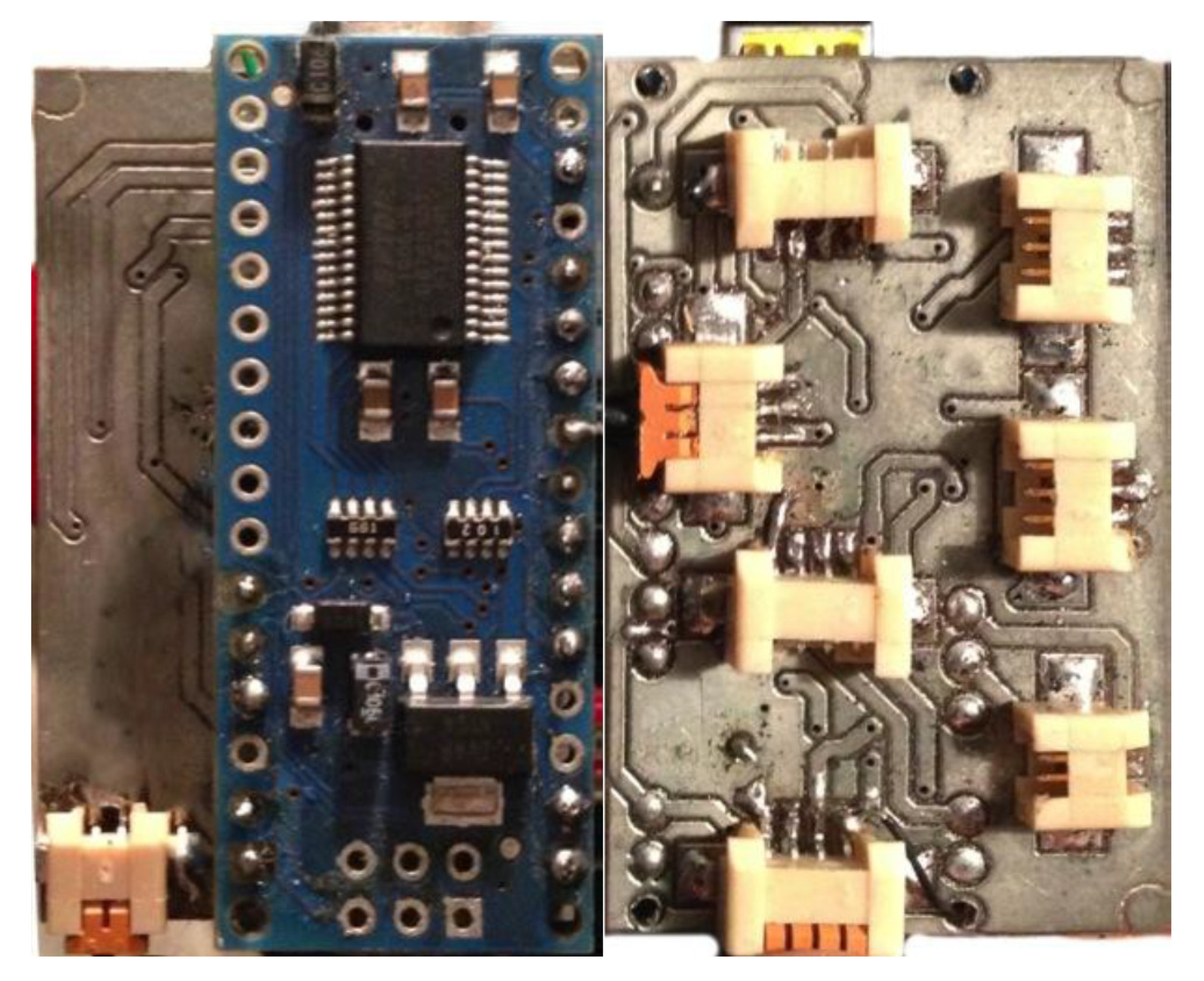
In Figure 4, we show a view of the PCB (printed circuit board) implemented. The motion sensor communicates with the microcontroller using the I2C protocol is connected to pins 4 and 5, corresponding to the SDA and SCL lines, respectively. For wireless communication, Bluetooth is connected to the RX and TX lines of the Arduino Nano that correspond to TX and RX, respectively.
The pressure sensors, resistors that depend on the pressure made, are connected in series with a resistance and act as a retainer splitter. This signal is read by pin 0 (analogue inputs to SI) up to pin 3 for the other sensors. The final device with all the mechanical and electronic elements has a weight of 390 g. A standard empty cup of coffee weighs 370–375 g. The grip of the device is similar to that of taking a cup. Other types of grips are possible, but the device is designed for grips that imply a certain strength rather than fine wean. In any case, the sensors allow to perceive fine variations of the orientation (tremors) that can be very useful in the diagnosis of neurodegenerative diseases.
2.2. Software Implementation
The software architecture used to offer service to different applications is presented. The prototype offers on-line device data to as many applications as needed, both locally and remotely. Data is sent from the device to the server using the Bluetooth component. Server application is responsible for distributing the data to any connected application. For force evaluation, we compare the data generated by the proposed device against two commercial devices dynamometer (Takei model 5101 TKK, Constant 14192-709E). We show the linearity of the three devices and the mean error for each device is calibrated.
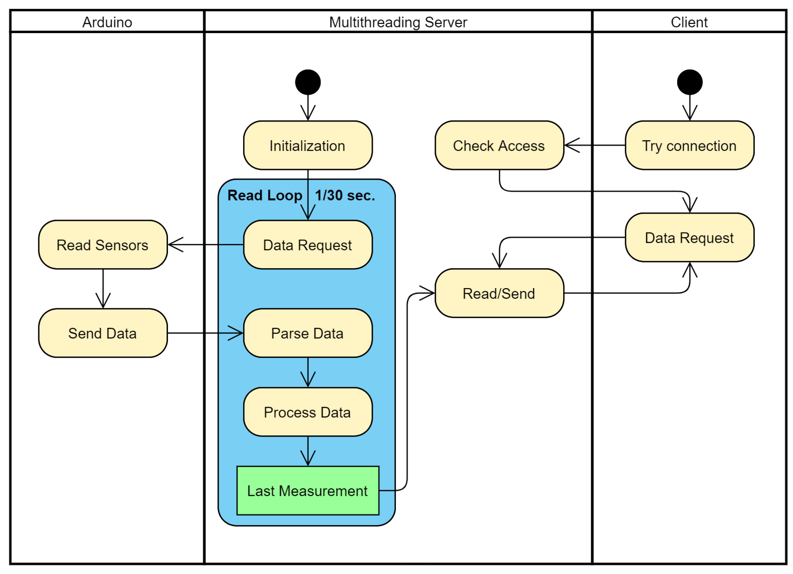
The server has been implemented using multithreading. One thread is in charge of communication with Arduino: data request, parsing, processing and storing. At the same time, it receives client’s requests. For each client, a thread is created. Figure 5 shows a simplified UML Communication Diagram between Arduino, server and client.
2.2.1. Sending Data from Control to Server
Data collected by the sensors is sent by the Arduino component via Bluetooth component. CSV format has been chosen among the different transmission package formats. Initially, CSV format was used for visual inspection, and it provides an easily readable format. With CSV format, debugging has been an easy job. Once the initial development tasks were completed, other binary formats were evaluated. After performance testing, we concluded that Bluetooth connection bandwidth, even low band rates, is enough to transmit in CSV text format. For this reason, even though CSV format was only considered for debugging and testing, the decision to maintain it as final transmission protocol was taken.
Data sent from device looks like:
RotationX, RotationY, RotationZ, Pressure1, Pressure2, Pressure3, Pressure4, Force1, Force2
15.2,4.52,7.236,0.01,0.9567,0,0,0.4599,0.2387# (1)
Rotation (angle) is expressed in degrees, while Pressure and Force measurements are values scaled between 0 and 1. At the end of each data package, a control character (#) has been added to mark the end of package.
2.2.2. Server Data Processing
Data is received in a computer that will carry out server tasks. The computer will provide this data to any clients as needed. Different operations are offered by the application that is running as service:
- GetDeviceConfiguration: returns information about the configuration: list of devices available for connection, device used to receive data, status of the device (searching, connecting or connected), and retry-time between connections.
- SetDeviceConfiguration: enables changes in service configuration, such as name of the device to connect to, and time between connection attempts.
- Connect: an asynchronous method to connect to the default device.
- Refresh: provides an updated list of available devices.
- GetData: returns the last device data obtained by the server.
The server runs permanently and is configurable. Data is provided to the application using WCF protocol. In addition to the data received from the controller, useful data is added: a frame identifier and a timestamp.
Any application that wishes to connect to the device must go through the server that acts as a gateway. An authentication layer to prevent unauthorized access can be added.
2.2.3. Client Application
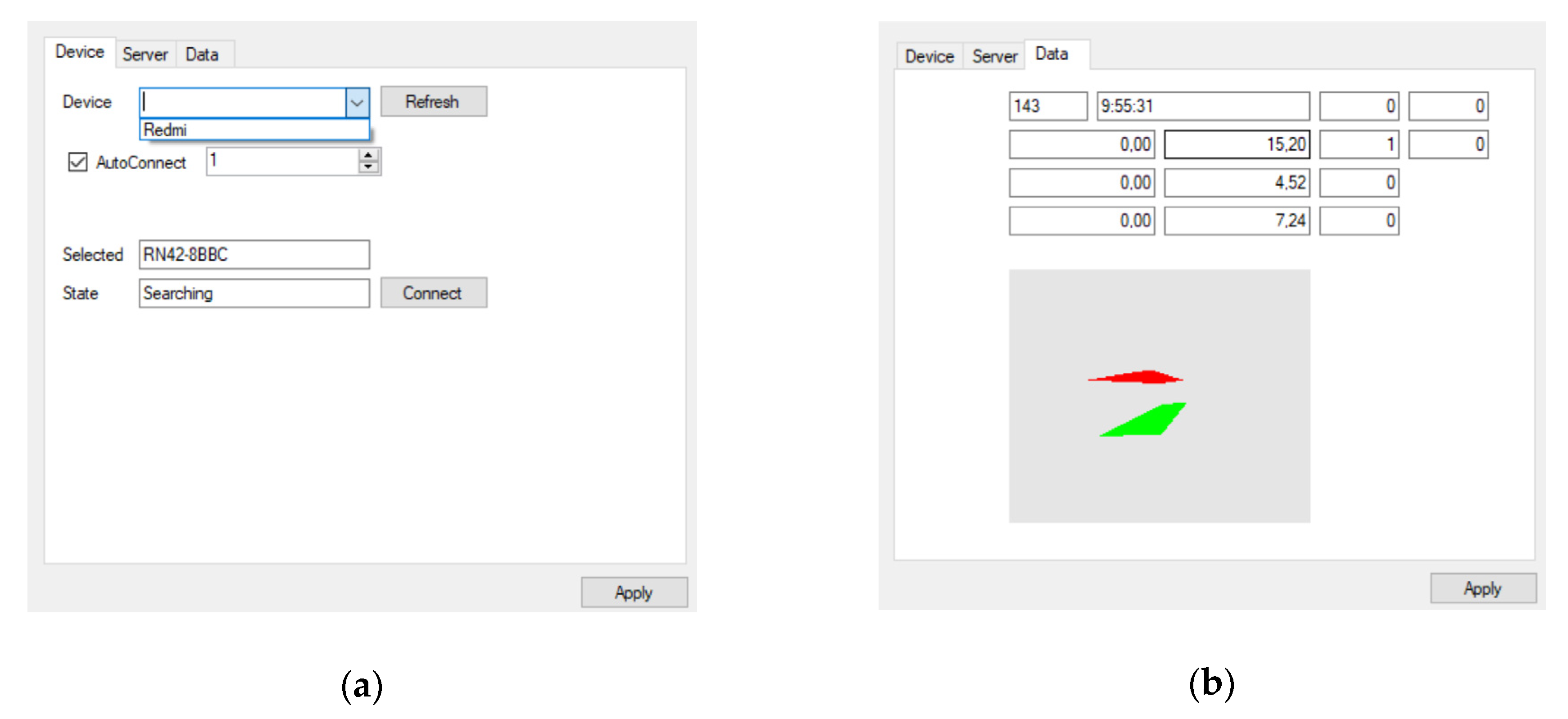
A client application, that verifies service and develops applications, has been developed in NET Framework 4.5. This test application allows the user to change server configuration by selecting the device between lists of available devices. The test client application displays the data numerically, a renderization that verifies the controller’s orientation has been included. Figure 6 shows two tabs of the application.
To better visualize the physical features, a graphical interface with 6 columns has been created. The first two columns correspond to the force gauges, and shows the maximum force exerted (kg) and the current force (kg), the average values are also indicated. The other four columns belong to the SFR sensors data and indicate the grip being exerted by the fingers in a uniform way. A cube is used to represent all the movements. In the upper part, a graph that represents the force exerted by the gauges is depicted.
3. Results and Validation
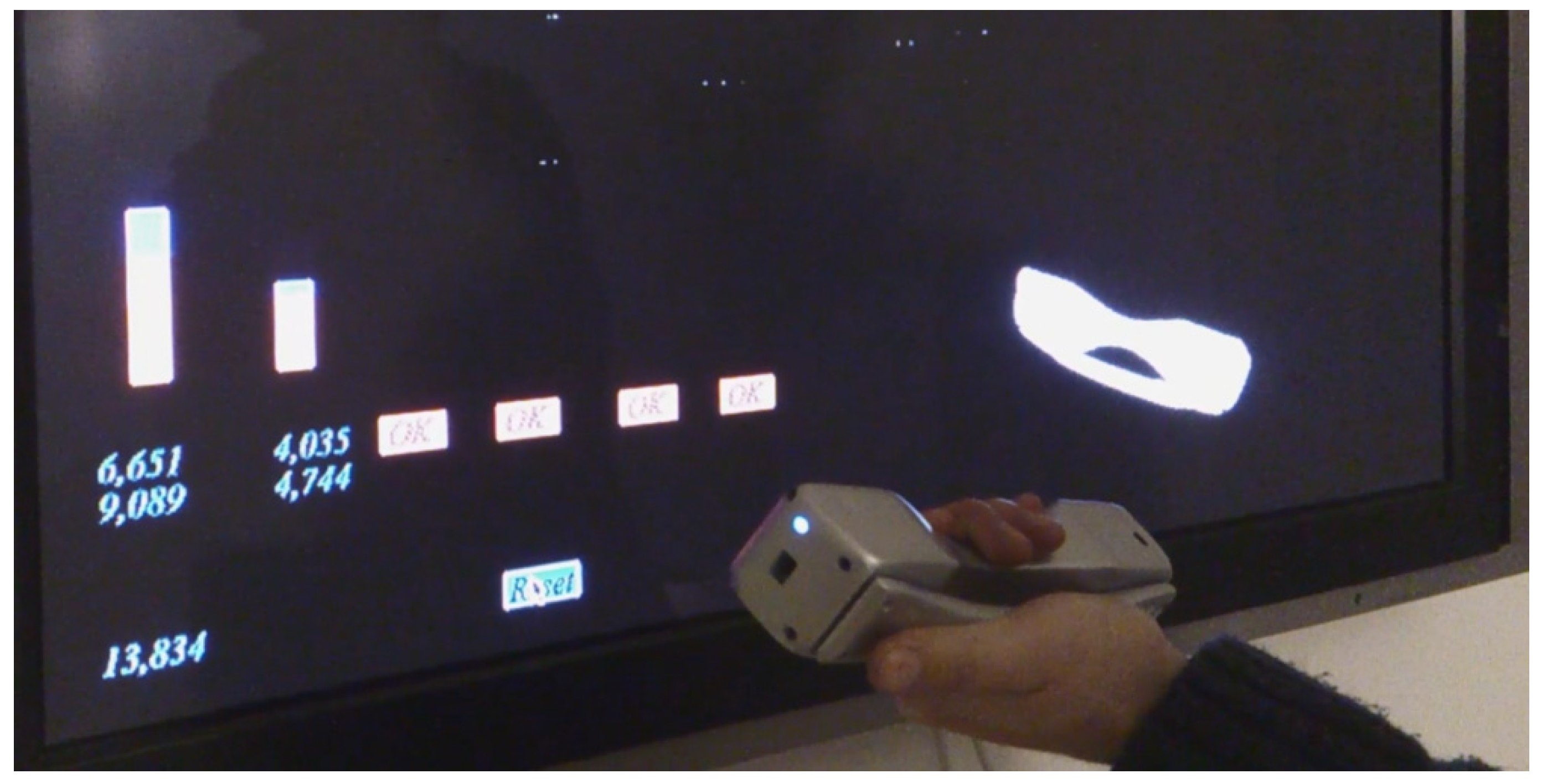
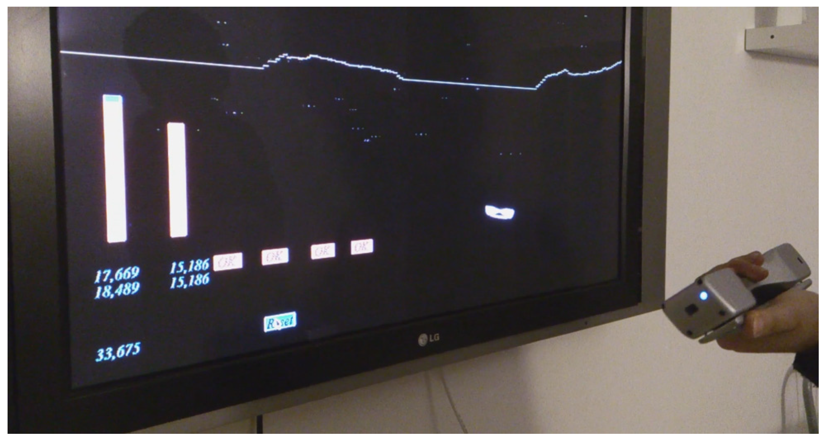
In this section, the main results of the work are presented. First of all, an example of execution of the testing application in Figure 7 and Figure 8. In this example, all parameters of the device are visualized in the screen. The force visual feedback given to the user includes force done and finger sensors activation. The virtual object changes position and orientation depending on hand and force values. In order to include visual variation of force sensors, a timeline is also provided. Furthermore, in every medical rehabilitation therapy the visual feedback will be adapted to specific objectives. An introductory video showing device performance is available online as additional information (http://ugivia.uib.es/video/ (accessed on 28 June 2021) or see Supplementary Materials). As a security measure, and in order to avoid the dropping or throwing of the device, a “velcro” band (similar to those in Valve Index Controllers) is included. This band guarantees that the hand grip is always in contact with the hand even when the user completely opens the hand.
3.1. Orientation Degree Error Measurement
The ITG-3200 datasheets specify that the maximum rotation speed is 2000°/s. This limitation does not pose a problem for the rehabilitation applications, for which the controller has been developed. The error made in the measurements due to noise must be considered. This error is not indicated in the specifications of the remote control, so an experiment to bound it has been carried out.
In order to measure noise, we have computed the probability of getting a measurement with an error higher than one degree.
The control has been immobilized for different orientations and the noise of the orientation measurement has been measured for 1000 records. A total of 35 recordings have been made in arbitrary orientations. The measurement results for the highest noise are shown below. They corresponded to the orientation yaw = −176.8162, pitch = −17.0508 and roll = 109.87212.
To carry out the statistical analysis, the orientations with the higher error (high mean error) have been selected. This set of measurements is called .
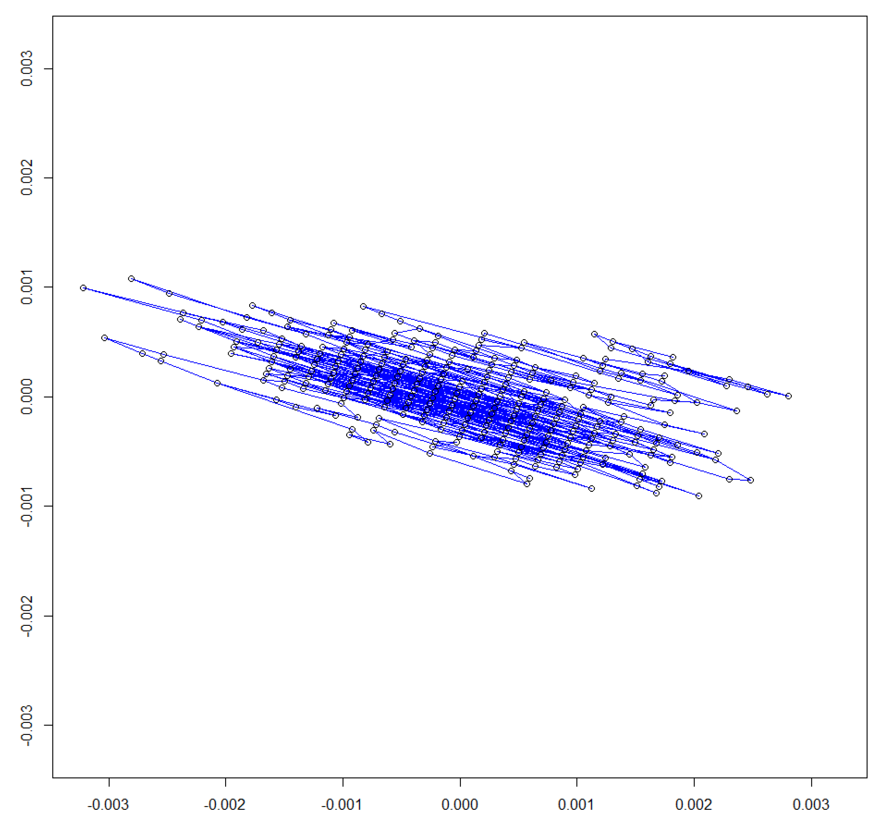
Figure 9 presents the graphical evolution of the orientation signal. Point (0, 0) corresponds to the average orientation (yaw = −176.8162, pitch = −17.0508 and roll = 109.87212). The error measurement is defined as the vector from the unitary orientation vector to the mean center orientation line.
For each orientation, we have stationary measurements, called . For each measurement, its error vector is computed as the 2D vector from the orientation to the mean orientation. The greatest scalar error is . In the worst scenario, 1.135321 × 10⁻⁵, which corresponds to a difference between measurement and mean measurement orientations of 0.1930557 degrees (). Furthermore, this is the maximum error obtained in the 35 arbitrary sets of measurements.
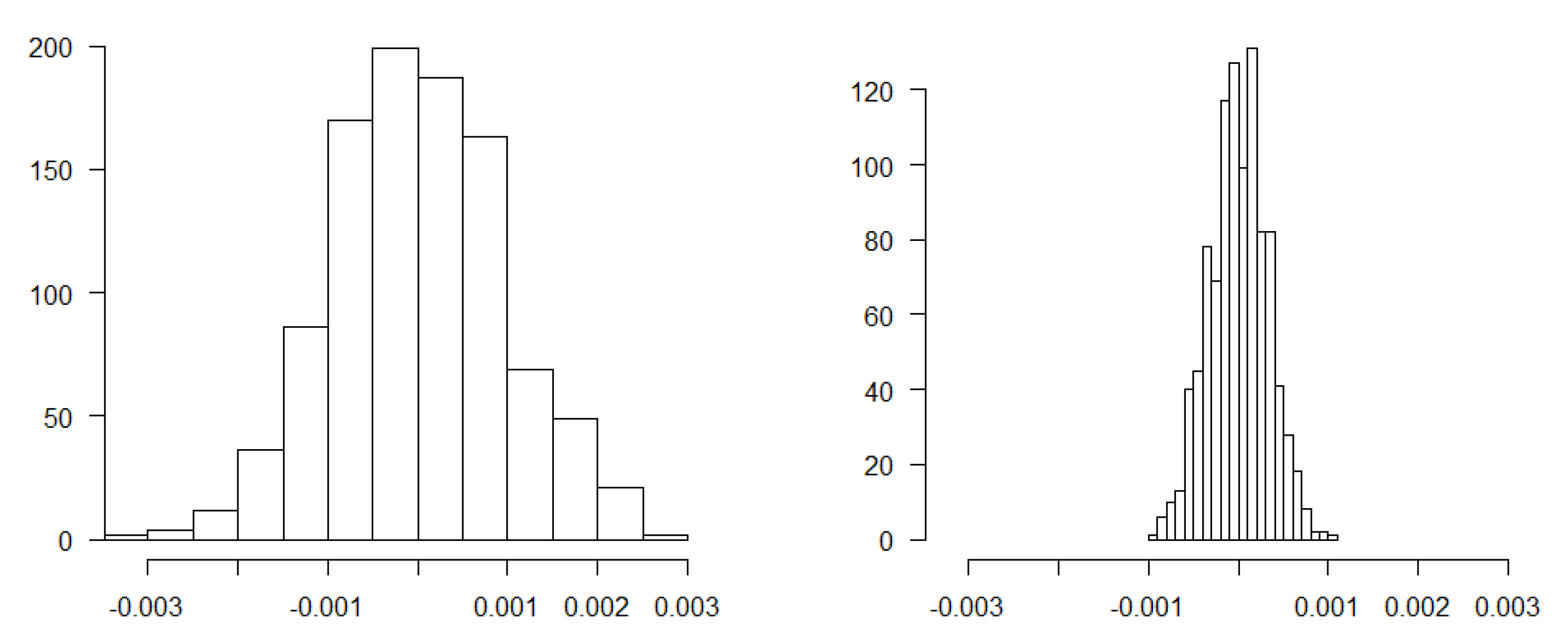
An analysis of error vectors set {, concludes that there is Gaussian noise along both axes. Therefore, this noise will be modelled as a bidimensional Gaussian noise. This noise has a correlation of −0.62904 according to the Pearson test. The noise error is split into two independent random variables, R1, obtained from the direction of greatest dispersion, and R2, the noise in the normal direction.
The Shapiro test has yielded p-values of 0.2827 and 0.5851 for R1 and R2, respectively. The parameters obtained are
R1 = N(μ1, σ1) = N(−3.141921 × 10⁻¹⁷, 0.000958003)
R2 = N(μ2, σ2) = N(1.134786 × 10⁻¹⁶, 0.0003242265)
Figure 10 shows the sample histograms for R1 and R2. The non-zero parameterization of the mean is due to lack of precision, but it can be assumed to be zero.
From this noise parameterization, which corresponds to the orientations with the higher error, the probability of obtaining noise greater than one degree is calculated as
The probability obtained from (1) is lower than 1 × 10⁻³⁵. From this study, we conclude that noise is less than one degree, which indicates that the data obtained can be used in a rehabilitation environment where orientation measurement errors less than one degree are acceptable [36].
3.2. Accuracy and Precision of the Force Measurements
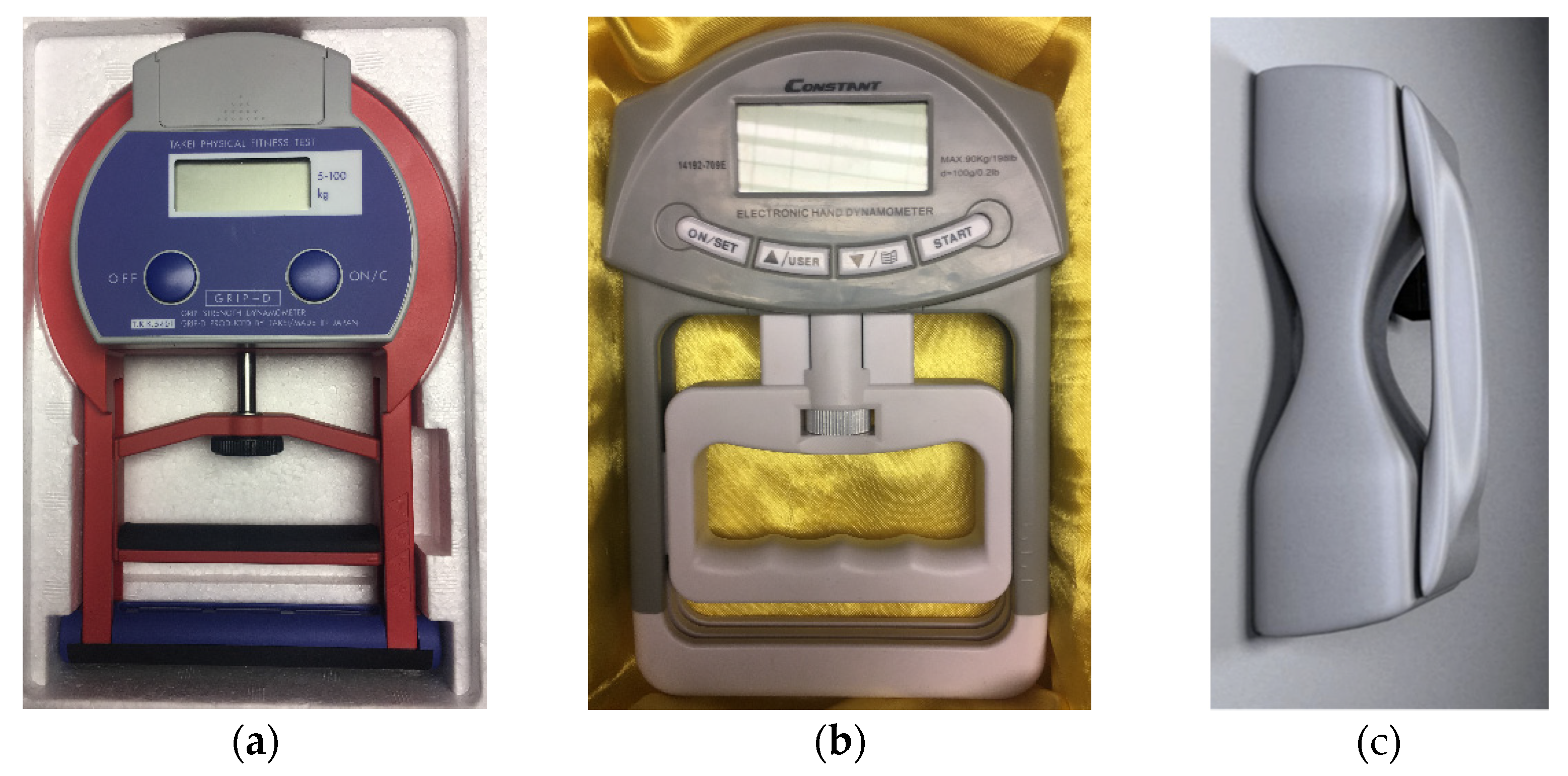
The analysis of the precision and accuracy of measurements was conducted with the dynamometers Takei® model 5101 TKK, (Figure 11a), Constant 14192-709E® (Figure 11b) and the Wireless Hand Grip device System of UIB (Figure 11c), the dynamometer Takei model 5101 TKK®® has a load limit between 0 and 100 kgf (980.66 newton), digital display, minimum reading of 0.5 kgf (4.9 newton), and rectified adjustable and complacent handle. The dynamometer Constant 14192-709E® has a load limit of 0 to 90 kgf (882.59 newton), digital display, minimum reading of 0.2 kgf (1.96 newton), and rigid and adjustable anatomical handle. The Wireless Hand Grip device System of UIB has a load limit between 0 and 90.7 kgf (888.86 newton), and was computerized with a minimum reading of 0.2 kgf (1.96 newton) with modified rigid and adjustable handle.
Each dynamometer was statically calibrated with the gradual application of factual loads (washers) in the center of their handles, as recommended by [32]. Other previous work to validate grip strength in normal population are presented in [37]. The weights pattern (average mass of 5.00 ± 0.0153 kgf, 49.033 ± 0.15 newton) were added one by one until they reached the final load of 60 kgf (588.39 newton), the highest force measurement limit assumed for a standard user among the three analyzed dynamometers. Figure 12 shows a scheme of the placement of the dynamometers in the cargo system, where calibration readings after the addition of each load and stabilization of the system were performed. For each load increase, the strength of the four values indicated on the dial or registration program of each dynamometer was registered.
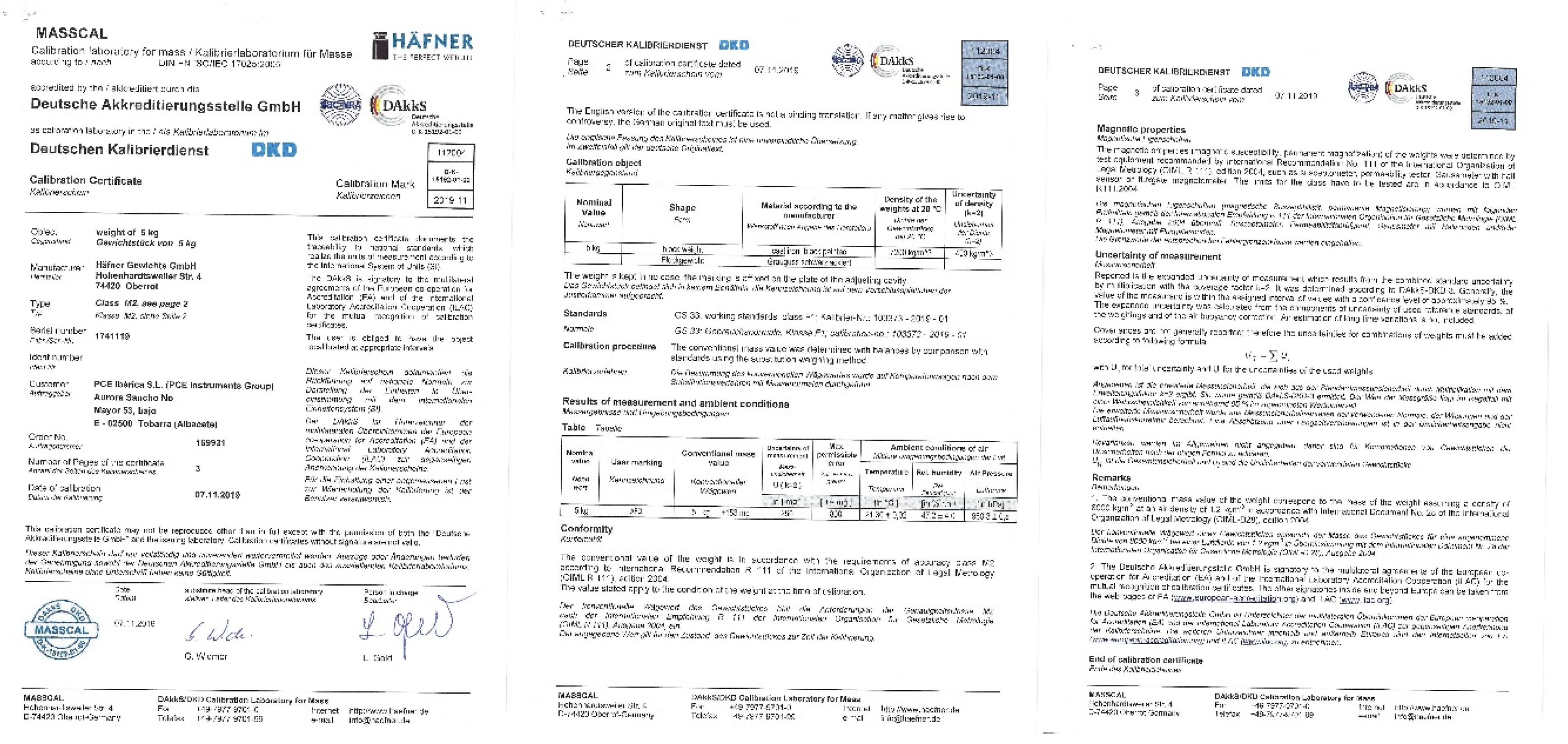
Figure 13 also shows the weights used to reach the maximum load. All weights possess the calibration certificate document that guarantees the traceability to national standards according to the International System Units (SI). Appendix A exhibits an example of the official certificate.
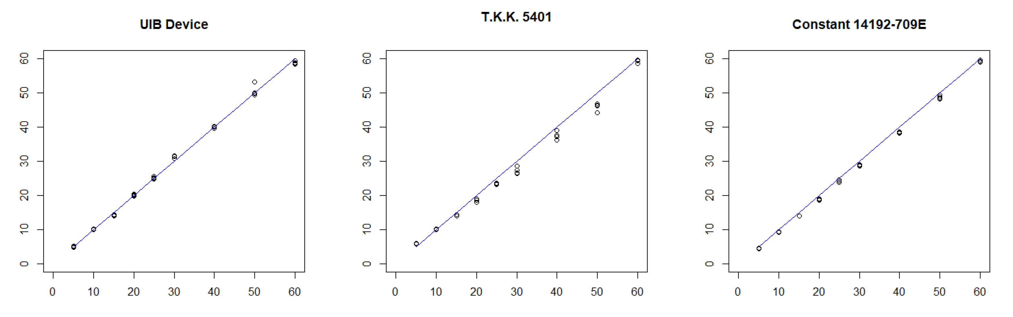
Calibration curves were obtained based on the relationship between the application of loads and the reading of the three dynamometers. These curves were constructed using simple linear regression by the method of minimal squares and analyzed according to the following procedure: (1) scatterplots of dynamometer versus calibrator loads for each device; (2) estimation of the respective linear regression models and determination of residuals; (3) calculation of the r2 value and verification of model’s assumptions; and (4) application of a covariance analysis model (ANCOVA), since the data provides Yd (load predicted value for a given dynamometer during the calibration process) and predictor x (the actual load value/washers). With this type of analysis, it was possible to model Yd as a linear function of x, where the coefficients of the regression line vary according to the device used. In this manner, the calibration was represented numerically by a table and graphically by a line described by the Equation (2):
where is the value predicted for a load for a given dynamometer, is the angular coefficient of the equation of regression (calibration factor), is the linear coefficient of the regression equation and (predictor) is the factual load value (washers).
Table 1 compares the measurements of the three dynamometers. The homogeneity of the variances has been analyzed using the Bartlett test, obtaining p-values of 0.9911, 0.7674 and 0.9718, respectively, for the three dynamometers. The necessary homoscedasticity condition is fulfilled, the regression model assumptions are satisfied, and the regression line coefficients are estimated (see Table 2). In all three cases, the p-value obtained accepts the model’s hypothesis, and the error obtained is acceptable. Figure 14 shows the representation of the three regression lines. This analysis shows that the controller presented (UIB Device) has similar measurements error to the Takei model, and is below the Constant model. The Takei model is used in several studies [38] as a standard force measurement device with good performance.
4. Discussion, Conclusions and Future Work
We have presented a novel wireless device that allows for the simultaneous measurement of motion and hand forces and analyzed its performance. The system has been tested against commercial force dynamometers (Takei model 5101 TKK, Constant 14192-709E) obtaining similar precision. The position and orientation have also been evaluated. Several statistical parameters are computed in order to verify the correct performance of device.
According to the values measured by the three goniometers considered and the analyses performed, we can affirm that the proposed UIB system performs adequately with precision comparable to those of the two commercial systems considered. The graphs presented show similar accuracy and precision.
These issues reflect the quality of the estimated parameters. The intention of this paper is to show the feasibility of the system. To improve the quality of the output data, further sensitivity analyses of different subsystems are required. A collection of serious games that validate the real interaction between a controlled user and real patients in a hospital environment are being developed. A possible application in the medical rehabilitation field of the proposed prototype is the classification and quantification of various hand motor tasks (specially grasping exercises for patients with neurological diseases).
In conclusion, this paper presents a new hand grip device designed for human–machine interaction developed for rehabilitation applications. The device combines 9-DoF kinematic sensing for hand and all fingers, hand position/orientation acquisition and force measurement. These aspects are integrated in an easy-to-use and low-cost system with wireless connection to the host computer. The key components are five finger contact sensors, which separately measure the contact or non-contact of fingers over the device. An inertial measurement unit facilitates hand position detection and orientation. Finally, two precise force sensors deliver, in real time, the hand force displayed by the user. In spite all of these improvements, the overall cost of the system is less than 300€. Preliminary validation experiments have been performed to examine quantitative features of the device. The proposed system is robust and low-cost; moreover, data is transmitted using standard wireless communication. This device goes beyond pressure sensing and gesture recognition and, therefore, opens up the possibility of gathering profound insights in the field. In particular, interaction optimization between the human body and its environment, virtual or augmented reality systems, have been examined. We have visual user feedback to virtual objects inside the application or to physical parameters. Furthermore, a new device, similar to the system presented in this paper, that also includes EMG, heart rate and skin conductance (EDA) biosignals synchronized with hand force and motion is being developed. Future work will focus on improving the electronics and software to increase the operating frequency. In addition, a validation process with control and real users is being considered. We have developed a set of Maze applications in order to control objects and reach objectives for some therapies.
5. Patents
The device presented in this paper is protected by Spanish Patent number 201330260. Mando Portátil Para Detección De Movimiento y Fuerza De Prensión. N/Ref.: MU17304ES00/F.
Supplementary Materials
The following are available online at https://0-www-mdpi-com.brum.beds.ac.uk/article/10.3390/app11136036/s1, Demo video of the Wireless Hand Device for Motion and Force Analysis.
Author Contributions
V.B. designed the whole device and performed the experiments. F.J.P. and M.R. assisted in conceiving of the principles, devices selection, wrote and proofread the paper. J.M.B. performed the testing, analyzed the data and validation. M.M.-J. reviewed and edited the paper. All authors have read and agreed to the published version of the manuscript.
Funding
This research was funded by the Ministerio de Economía, Industria y Competitividad (MINECO), the Agencia Estatal de Investigación (AEI) and the European Regional Development Funds (ERDF, EU) for its support to the project TIN2015-67149-C3-2-R (MINECO/AEI/ERDF, EU) and PERGAMEX RTI2018-096986-B-C31 (MINECO/AEI/ERDF, EU), PID2019-104829RA-I00/AEI/10.13039/501100011033 (MICINN).
Institutional Review Board Statement
Not applicable.
Informed Consent Statement
Not applicable.
Conflicts of Interest
The authors declare no conflict of interest.
Appendix A
The appendix includes an example file of the official calibration certificate document for the reference weight use in the experiment for UIB hand grip validation (Figure A1).
Figure A1.
Calibration Certificate Document.

References
- Suarez, J.; Murphy, R.R. Hand gesture recognition with depth images: A review. In Proceedings of the RO-MAN, Paris, France, 9–13 September 2012; pp. 411–417. [Google Scholar]
- Palacios, J.; Sagüés, C.; Montijano, E.; Llorente, S. Human-computer interaction based on hand gestures using RGB-D sensors. Sensors 2013, 13, 11842. [Google Scholar] [CrossRef]
- Zhou, F.; Duh, H.B.; Billinghurst, M. Trends in augmented reality tracking, interaction and display: A review of ten years of ISMAR. In Proceedings of the 2008 7th IEEE/ACM International Symposium on Mixed and Augmented Reality, Cambridge, UK, 15–18 September 2008. [Google Scholar] [CrossRef] [Green Version]
- Pitarch, E.; Yang, J.; Abdel-Malek, K. SANTOS™ Hand: A 25 Degree-of-Freedom Model; SAE Technical Paper 2005-01-2727; SAE: Warrendale, PA, USA, 2005. [Google Scholar] [CrossRef]
- Dipietro, L.; Sabatini, A.M.; Dario, P. A survey of glove-based systems and their applications. IEEE Trans. Syst. Man Cybern. Part C Appl. Rev. 2008, 38, 461–482. [Google Scholar] [CrossRef]
- Rautaray, S.S.; Agrawal, A. Vision based hand gesture recognition for human computer interaction: A survey. Artif. Intell. Rev. 2015, 43, 1–54. [Google Scholar] [CrossRef]
- Khaleghi, B.; Khamis, A.; Karray, F.O.; Razavi, S.N. Multisensor data fusion: A review of the state-of-the-art. Inf. Fusion 2013, 14, 28–44. [Google Scholar] [CrossRef]
- Ferraris, C.; Nerino, R.; Chimienti, A.; Pettiti, G.; Cau, N.; Cimolin, V.; Azzaro, C.; Albani, G.; Priano, L.; Mauro, A. A Self-Managed System for Automated Assessment of UPDRS Upper Limb Tasks in Parkinson’s disease. Sensors 2018, 18, 3523. [Google Scholar] [CrossRef] [Green Version]
- Arkenbout, E.A.; de Winter, J.C.; Breedveld, P. Robust Hand Motion Tracking through Data Fusion of 5DT Data Glove and Nimble VR Kinect Camera Measurements. Sensors 2015, 15, 31644–31671. [Google Scholar] [CrossRef] [PubMed]
- Kim, D.H.; Lee, S.W.; Park, H.-S. Improving Kinematic Accuracy of Soft Wearable Data Gloves by Optimizing Sensor Locations. Sensors 2016, 16, 766. [Google Scholar] [CrossRef] [PubMed] [Green Version]
- Kortier, H.G.; Schepers, H.M.; Veltink, P.H. Identification of Object Dynamics Using Hand Worn Motion and Force Sensors. Sensors 2016, 16, 2005. [Google Scholar] [CrossRef] [PubMed] [Green Version]
- Ben-Tzvi, P.; Ma, Z. Sensing and force-feedback exoskeleton (safe) robotic glove. IEEE Trans. Neural Syst. Rehabil. Eng. 2015, 23, 992–1002. [Google Scholar] [CrossRef] [PubMed]
- Tiwana, M.; Redmond, S.; Lovell, N. A review of tactile sensing technologies with applications in biomedical engineering. Sens. Actuators A Phys. 2012, 179, 17–31. [Google Scholar] [CrossRef]
- Dahiya, R.; Metta, G.; Valle, M.; Sandini, G. Tactile sensing—From humans to humanoids. IEEE Trans. Robot. 2010, 26, 1–20. [Google Scholar] [CrossRef]
- Puangmali, P.; Althoefer, K.; Seneviratne, L.; Murphy, D.; Dasgupta, P. State-of-the-art in force and tactile sensing for minimally invasive surgery. IEEE Sens. J. 2008, 8, 371–381. [Google Scholar] [CrossRef]
- Heo, P.; Gu, G.; Lee, S.; Rhee, K.; Kim, J. Current hand exoskeleton technologies for rehabilitation and assistive engineering. Int. J. Precis. Eng. Manuf. 2012, 13, 807–824. [Google Scholar] [CrossRef]
- Lee, Y.H.; Kim, M.; Kim, H.Y.; Lee, D.; You, B.J. CHICAP: Low-cost hand motion capture device using 3D magnetic sensors for manipulation of virtual objects. In Proceedings of the SIGGRAPH ‘18 Emerging Technologies, Vancouver, BC, Canada, 12–16 August 2018. ACM 978-1-4503-5810-1/18/08. [Google Scholar] [CrossRef]
- Weber, P.; Rueckert, E.; Calandra, R.; Peters, J. A Low-cost Sensor Glove with Vibrotactile Feedback and Multiple Finger Joint and Hand Motion Sensing for Human-Robot Interaction. In Proceedings of the IEEE International Symposium on Robot and Human Interactive Communication (RO-MAN), New York, NY, USA, 26–31 August 2016. [Google Scholar] [CrossRef]
- Ju, Z.; Liu, H. Human Hand Motion Analysis with Multisensory Information. IEEE/ASME Trans. Mechatron. 2014, 19, 456–466. [Google Scholar] [CrossRef]
- Shah, K.N.; Rathod, K.R.; Agravat, S.J. A survey on Human Computer Interaction Mechanism Using Finger Tracking. Int. J. Comput. Trends Technol. 2014, 7, 174–177. [Google Scholar] [CrossRef] [Green Version]
- Xue, Y.; Ju, Z.; Xiang, K.; Chen, J.; Liu, H. Multimodal Human Hand Motion Sensing and Analysis—A Review. IEEE Trans. Cogn. Dev. Syst. 2018, 11, 162–175. [Google Scholar] [CrossRef]
- Kim, J.H.; Thang, N.D.; Kim, T.S. 3-D Hand Motion Tracking and Gesture Recognition Using a Data Glove. In Proceedings of the IEEE International Symposium on Industrial Electronics (ISlE 2009), Seoul Olympic Parktel, Seoul, Korea, 5–8 July 2009. [Google Scholar]
- Ancillao, A.; Galli, M.; Vimercati, S.; Albertinia, G. An optoelectronic based approach for handwriting capture. Comput. Methods Programss Biomed. III 2013, 111, 357–365. [Google Scholar] [CrossRef]
- Ma, Y.; Mao, Z.; Jia, W.; Li, C.; Yang, J.; Sun, M. Magnetic Hand Tracking for Human-Computer Interface. IEEE Trans. Magn. 2011, 47, 970–973. [Google Scholar] [CrossRef]
- Nishiyama, M.; Watanabe, K. Wearable Sensing Glove With Embedded Hetero-Core Fiber-Optic Nerves for Unconstrained Hand Motion Capture. IEEE Trans. Instrum. Meas. 2009, 58, 3995–4000. [Google Scholar] [CrossRef]
- Tarchanidis, K.N.; Lygouras, J.N. Data glove with a force sensor, IMTC 2001. In Proceedings of the 18th IEEE Instrumentation and Measurement Technology Conference. Rediscovering Measurement in the Age of Informatics (Cat. No.01CH 37188), Budapest, Hungary, 21–23 May 2001; Volume 1, pp. 380–385. [Google Scholar] [CrossRef]
- Nasiri, S.; Khosravani, M.R. Progress and challenges in fabrication of wearable sensors for health monitoring. Sens. Actuators A Phys. 2020, 312, 112105. [Google Scholar] [CrossRef]
- Nižetić, S.; Pivac, N.; Zanki, V.; Papadopoulos, A.M. Application of smart wearable sensors in office buildings for modelling of occupants’ metabolic responses. Energy Build. 2020, 226, 110399. [Google Scholar] [CrossRef]
- Camilla, C.L.; Zhan, Y. Development of an updated normative data table for hand grip and pinch strength: A pilot study. Comput. Biol. Med. 2017, 86, 40–46. [Google Scholar]
- Wang, Y.-C.; Bohannon, R.W.; Li, X.; Yen, S.-C.; Sindhu, B.; Kapellusch, J. Summary of grip strength measurements obtained in the 2011–2012 and 2013–2014 National Health and Nutrition Examination Surveys. J. Hand Ther. 2018, 32, 489–496. [Google Scholar] [CrossRef]
- Edgren, C.S.; Radwin, R.G.; Irwin, C.B. Grip Force Vectors for Varying Handle Diameters and Hand Sizes. Hum. Factors J. Hum. Factors Ergon. Soc. 2004, 46, 244–251. [Google Scholar] [CrossRef] [PubMed]
- Amaral, J.F.; Mancini, M.; Novo Junior, J.M. Comparison of three hand dynamometers in relation to the accuracy and precision of the measurements. Rev. Bras. Fisioter. 2012, 16, 216–224. [Google Scholar] [CrossRef] [PubMed]
- Lee, K.S.; Jung, M.C. Ergonomic evaluation of biomechanical hand function. Saf. Health Work. 2014, 6, 9–17. [Google Scholar] [CrossRef] [Green Version]
- Roberts, H.C.; Denison, H.J.; Martin, H.J.; Patel, H.P.; Syddall, H.; Cooper, C.; Sayer, A.A. A review of the measurement of grip strength in clinical and epidemiological studies: Towards a standardised approach. Age Ageing 2011, 40, 423–429. [Google Scholar] [CrossRef] [PubMed] [Green Version]
- Parmar, S.; Khodasevych, I.; Troynikov, O. Evaluation of Flexible Force Sensors for Pressure Monitoring in Treatment of Chronic Venous Disorders. Sensors 2017, 17, 1923. [Google Scholar] [CrossRef]
- Zhang, L.; Li, J.; Cui, Y.; Dong, M.; Fang, B.; Zhang, P. Design and performance analysis of a parallel wrist rehabilitation robot (PWRR). Robot. Auton. Syst. 2020, 125, 103390. [Google Scholar] [CrossRef]
- Bellace, J.V.; Healy, D.; Besser, M.P.; Byron, T.; Hohman, L. Validity of the Dexter Evaluation System’s Jamar dynamometer attachment for assessment of hand grip strength in a normal population. J. Hand Ther. 2000, 13, 46–51. [Google Scholar] [CrossRef]
- Gatt, I.; Smith-Moore, S.; Steggles, C.; Loosemore, M. The Takei Handheld Dynamometer: An Effective Clinical Outcome Measure Tool for Hand and Wrist Function in Boxing. Hand 2018, 13, 319–324. [Google Scholar] [CrossRef] [PubMed]
Figure 1.
Shaders prototype and their components: (a) controller case, (b) Arduino, (c) Instrumentation Amplifier (AD627), (d) IMU sensor, (e) force sensors, (f) Interlink FSR sensor, and (g) battery.
Figure 1.
Shaders prototype and their components: (a) controller case, (b) Arduino, (c) Instrumentation Amplifier (AD627), (d) IMU sensor, (e) force sensors, (f) Interlink FSR sensor, and (g) battery.

Figure 2.
Hardware components of the device.

Figure 3.
Force sensors, IMU sensor, and Interlink FSR sensor.

Figure 4.
PCB prototype.

Figure 5.
UML communication diagram. Server is running in multithread. Main thread communicates with Arduino, and one thread runs for each client.
Figure 5.
UML communication diagram. Server is running in multithread. Main thread communicates with Arduino, and one thread runs for each client.

Figure 6.
(a) Tab that provides the user with a list of available devices. (b) Tab that provides the user with data obtained from service.
Figure 6.
(a) Tab that provides the user with a list of available devices. (b) Tab that provides the user with data obtained from service.

Figure 7.
Force and motion of wireless hand device.

Figure 8.
Virtual object on the screen.

Figure 9.
Stability measurement for orientation yaw = −176.8162, pitch = −17.0508 and roll = 109.87212. The difference between orientations has been measured by the L2 norm of the projection of the orientation on the unit sphere. The maximum error obtained is 1.135321 × 10⁻⁵, which is equivalent to a maximum error in degrees of 0.1930557 in degrees.

Figure 10.
Histogram of measurements around its mean. On the left, the histogram of the measurements in the loudest direction. On the right side, the histogram of measurements in the normal direction.
Figure 10.
Histogram of measurements around its mean. On the left, the histogram of the measurements in the loudest direction. On the right side, the histogram of measurements in the normal direction.

Figure 11.
(a) Takei 5101 TKK, (b) Constant 14192-709E, (c) hand grip device UIB.

Figure 12.
Dynamometers cargo system. (a) Takei 5101 TKK, (b) Constant 14192-709E, (c) hand grip device UIB
Figure 12.
Dynamometers cargo system. (a) Takei 5101 TKK, (b) Constant 14192-709E, (c) hand grip device UIB

Figure 13.
Calibrated weight set (Type: Class M2, calibration date 07/11/2019).

Figure 14.
Measurements and linear regression.


Table 1.
Measurement table with calibration load and display dynamometer value.
| Weight | UIB Device | T.K.K. 5401 | Constant 14192-709E | |||||||||
|---|---|---|---|---|---|---|---|---|---|---|---|---|
| Kgs | Measure 1 | Measure 2 | Measure 3 | Measure 4 | Measure 1 | Measure 2 | Measure 3 | Measure 4 | Measure 1 | Measure 2 | Measure 3 | Measure 4 |
| 5 | 5.1 | 5.0 | 4.9 | 4.8 | 6.0 | 5.9 | 5.8 | 5.8 | 4.5 | 4.4 | 4.5 | 4.5 |
| 10 | 10.0 | 10.1 | 10.1 | 9.9 | 10.1 | 10.0 | 10.0 | 9.9 | 9.2 | 9.2 | 9.4 | 9.2 |
| 15 | 14.1 | 14.3 | 13.9 | 14.0 | 14.3 | 14.4 | 14.4 | 14.0 | 13.9 | 14.0 | 13.9 | 14.0 |
| 20 | 20.4 | 19.8 | 20.2 | 20.0 | 17.9 | 19.0 | 18.5 | 18.5 | 18.5 | 18.9 | 18.8 | 18.6 |
| 25 | 24.8 | 24.9 | 25.1 | 25.5 | 23.5 | 23.2 | 23.2 | 23.3 | 24.5 | 23.8 | 24.1 | 23.8 |
| 30 | 31.5 | 30.8 | 31.3 | 30.8 | 28.6 | 26.5 | 26.4 | 27.3 | 28.7 | 28.7 | 28.5 | 29.0 |
| 40 | 40.2 | 40.2 | 39.9 | 39.5 | 36.1 | 37.6 | 37.1 | 38.9 | 38.6 | 38.4 | 38.1 | 38.1 |
| 50 | 49.8 | 53.3 | 49.5 | 50.1 | 46.5 | 44.2 | 46.2 | 46.8 | 48.4 | 49.4 | 48.3 | 48.9 |
| 60 | 58.8 | 59.5 | 58.6 | 58.5 | 58.6 | 58.7 | 59.5 | 59.6 | 59.1 | 59.3 | 59.7 | 59.1 |
Table 2.
Linear regression results . The linear model’s coefficients, value, and p-value for each device.
Table 2.
Linear regression results . The linear model’s coefficients, value, and p-value for each device.
| UIB Device | T.K.K. 5401 | Constant | |
|---|---|---|---|
| 0.996872 | 0.94814 | 0.99374 | |
| 0.066212 | −0.03886 | −0.87826 | |
| 0.9976 | 0.9942 | 0.9995 | |
| -value | <2.2 × 10⁻¹⁶ | <2.2 × 10⁻¹⁶ | <2.2 × 10⁻¹⁶ |
Publisher’s Note: MDPI stays neutral with regard to jurisdictional claims in published maps and institutional affiliations. |
© 2021 by the authors. Licensee MDPI, Basel, Switzerland. This article is an open access article distributed under the terms and conditions of the Creative Commons Attribution (CC BY) license (https://creativecommons.org/licenses/by/4.0/).
Share and Cite
MDPI and ACS Style
Becerra, V.; Perales, F.J.; Roca, M.; Buades, J.M.; Miró-Julià, M. A Wireless Hand Grip Device for Motion and Force Analysis. Appl. Sci. 2021, 11, 6036. https://0-doi-org.brum.beds.ac.uk/10.3390/app11136036
AMA Style
Becerra V, Perales FJ, Roca M, Buades JM, Miró-Julià M. A Wireless Hand Grip Device for Motion and Force Analysis. Applied Sciences. 2021; 11(13):6036. https://0-doi-org.brum.beds.ac.uk/10.3390/app11136036
Chicago/Turabian StyleBecerra, Victor, Francisco J. Perales, Miquel Roca, José M. Buades, and Margaret Miró-Julià. 2021. "A Wireless Hand Grip Device for Motion and Force Analysis" Applied Sciences 11, no. 13: 6036. https://0-doi-org.brum.beds.ac.uk/10.3390/app11136036
Note that from the first issue of 2016, this journal uses article numbers instead of page numbers. See further details here.