
Accuracy and Feasibility of a Zero-Setup Implant Guide System Made of a Light-Cured Composite Resin with Simultaneous Flapless Sinus Augmentation: A Pilot Study

 , , and
Abstract
:1. Introduction
2. Materials and Methods
2.1. Study Design and Patient Selection
2.1.1. Inclusion Criteria
2.1.2. Exclusion Criteria
2.2. Treatment Protocol
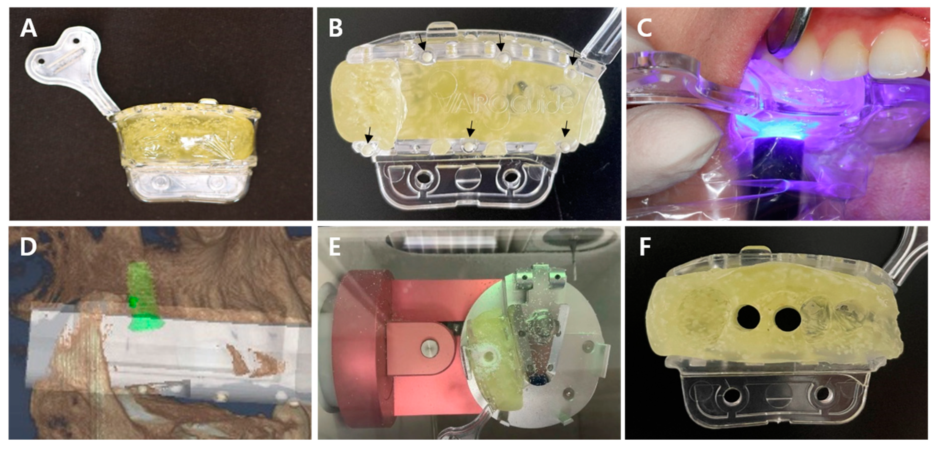
2.2.1. VARO Guide Fabrication
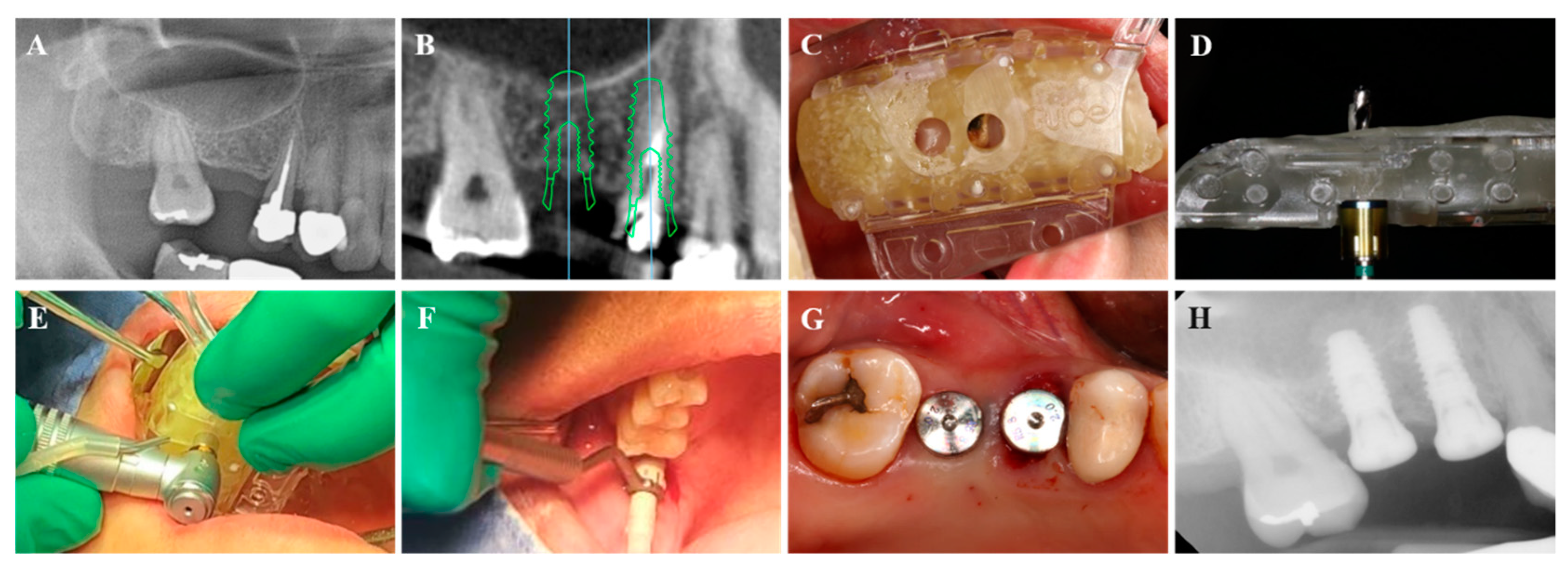
2.2.2. Fully-Guided Implant Placement with Flapless Crestal Sinus Augmentation
2.3. Outcomes
2.3.1. Clinical Observation
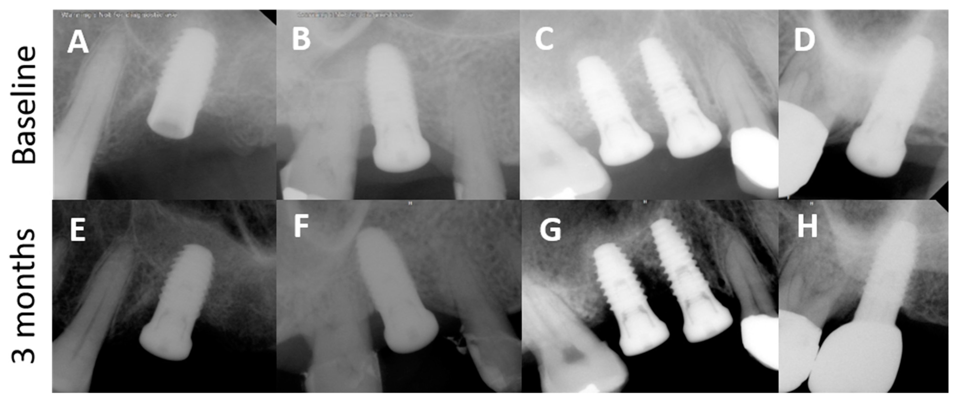
2.3.2. Radiographic Observation
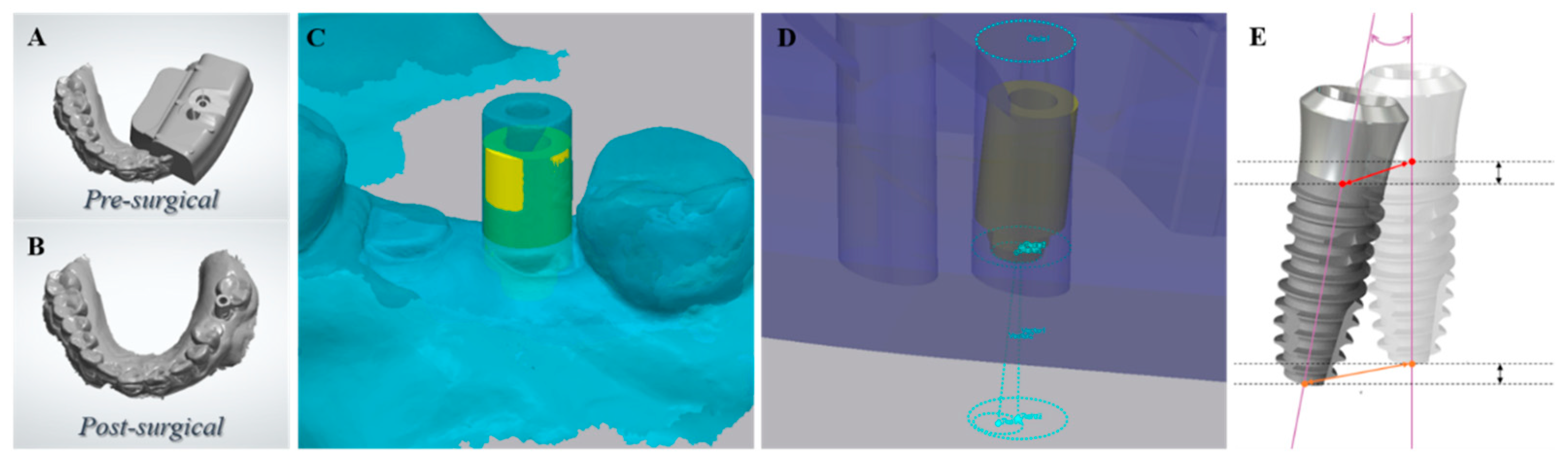
2.3.3. Accuracy of Implant Placement
Superimposition of the Virtually Planned Implant and the Actually Placed Implant
Parameters for Accuracy of Implant Placement
- Vertical deviation (mm): the vertical distance between the planned and placed fixture apices.
- Angular deviation (°): the angle between the axes of planned and placed fixtures.
- Horizontal platform deviation (mm): the horizontal distance between the planned and placed fixtures at the base of the transmucosal component of the tissue level implants.
- Horizontal apex deviation (mm): the horizontal distance between the planned and placed fixture apices.
2.3.4. Implant Stability
3. Results
3.1. Clinical Observation
3.2. Radiographic Observation
3.3. Accuracy of Implant Placement Using the VARO Guide
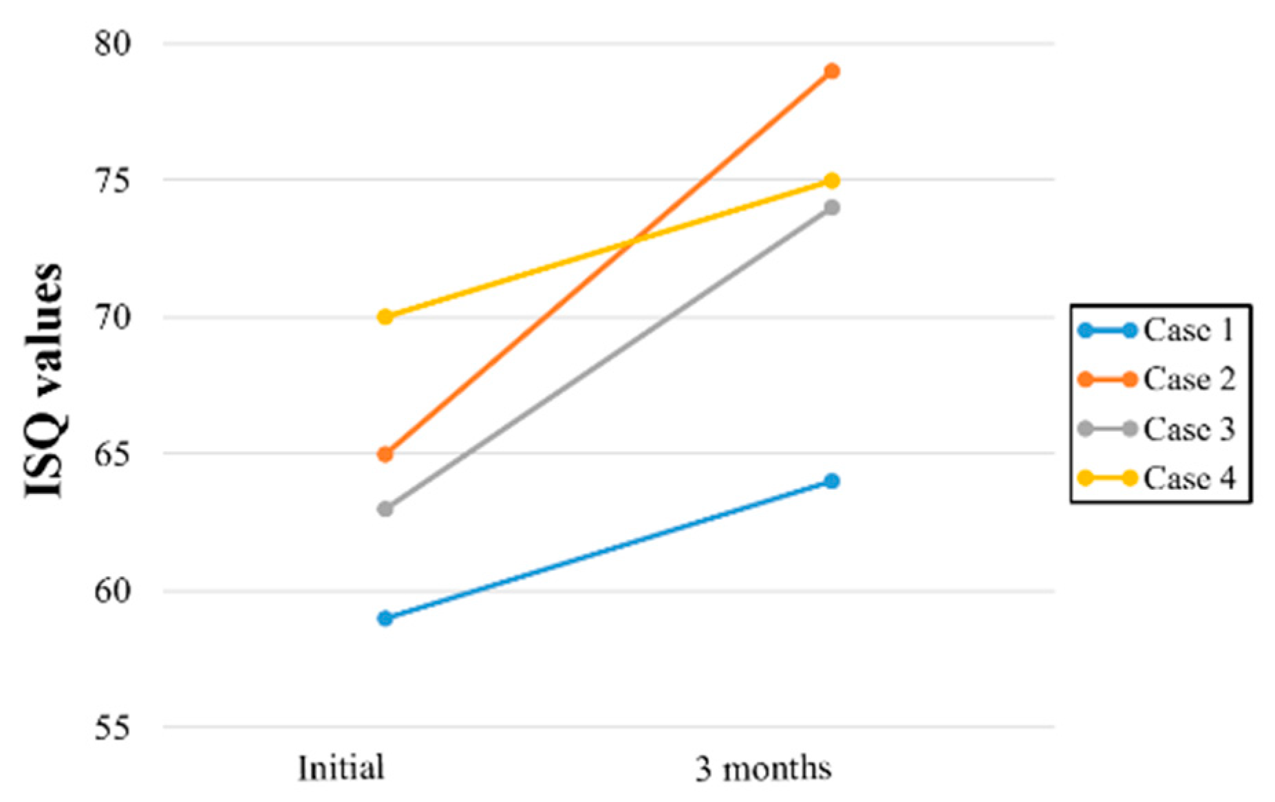
3.4. Implant Stability
4. Discussion
5. Conclusions
Author Contributions
Funding
Institutional Review Board Statement
Informed Consent Statement
Data Availability Statement
Conflicts of Interest
References
- Testori, T.; Weinstein, T.; Scutellà, F.; Wang, H.-L.; Zucchelli, G. Implant placement in the esthetic area: Criteria for positioning single and multiple implants. Periodontology 2000 2018, 77, 176–196. [Google Scholar] [CrossRef]
- D’Haese, J.; Ackhurst, J.; Wismeijer, D.; De Bruyn, H.; Tahmaseb, A. Current state of the art of computer-guided implant surgery. Periodontol 2000 2017, 73, 121–133. [Google Scholar] [CrossRef] [PubMed]
- Romanos, G.E.; Delgado-Ruiz, R.; Sculean, A. Concepts for prevention of complications in implant therapy. Periodontology 2000 2019, 81, 7–17. [Google Scholar] [CrossRef]
- Choi, W.; Nguyen, B.C.; Doan, A.; Girod, S.; Gaudilliere, B.; Gaudilliere, D. Freehand Versus Guided Surgery: Factors Influencing Accuracy of Dental Implant Placement. Implant Dent. 2017, 26, 500–509. [Google Scholar] [CrossRef]
- Smitkarn, P.; Subbalekha, K.; Mattheos, N.; Pimkhaokham, A. The accuracy of single-tooth implants placed using fully digital-guided surgery and freehand implant surgery. J. Clin. Periodontol. 2019, 46, 949–957. [Google Scholar] [CrossRef] [PubMed]
- Park, J.Y.; Song, Y.W.; Park, S.H.; Kim, J.H.; Park, J.M.; Lee, J.S. Clinical factors influencing implant positioning by guided surgery using a nonmetal sleeve template in the partially edentulous ridge: Multiple regression analysis of a prospective cohort. Clin. Oral Implants Res. 2020, 31, 1187–1198. [Google Scholar] [CrossRef]
- Velasco-Ortega, E.; Jiménez-Guerra, A.; Ortiz-Garcia, I.; Moreno-Muñoz, J.; Núñez-Márquez, E.; Cabanillas-Balsera, D.; López-López, J.; Monsalve-Guil, L. Immediate Loading of Implants Placed by Guided Surgery in Geriatric Edentulous Mandible Patients. Int. J. Environ. Res. Public Health 2021, 18, 4125. [Google Scholar] [CrossRef]
- Kan, J.Y.K.; Rungcharassaeng, K.; Deflorian, M.; Weinstein, T.; Wang, H.-L.; Testori, T. Immediate implant placement and provisionalization of maxillary anterior single implants. Periodontology 2000 2018, 77, 197–212. [Google Scholar] [CrossRef]
- Marra, R.; Acocella, A.; Rispoli, A.; Sacco, R.; Ganz, S.D.; Blasi, A. Full-mouth rehabilitation with immediate loading of implants inserted with computer-guided flap-less surgery: A 3-year multicenter clinical evaluation with oral health impact profile. Implant Dent. 2013, 22, 444–452. [Google Scholar] [CrossRef] [PubMed]
- Pozzi, A.; Tallarico, M.; Marchetti, M.; Scarfò, B.; Esposito, M. Computer-guided versus free-hand placement of immediately loaded dental implants: 1-year post-loading results of a multicentre randomised controlled trial. Eur. J. Oral Implantol. 2014, 7, 229–242. [Google Scholar] [PubMed]
- Song, Y.; Kim, J.; Kim, J.-H.; Park, J.-M.; Jung, U.-W.; Cha, J.-K. Accuracy of Dental Implant Placement by a Novel In-House Model-Free and Zero-Setup Fully Guided Surgical Template Made of a Light-Cured Composite Resin (VARO Guide®): A Comparative In Vitro Study. Materials 2021, 14, 4023. [Google Scholar] [CrossRef]
- Siqueira, R.; Chen, Z.; Galli, M.; Saleh, I.; Wang, H.; Chan, H. Does a fully digital workflow improve the accuracy of computer-assisted implant surgery in partially edentulous patients? A systematic review of clinical trials. Clin. Implant. Dent. Relat. Res. 2020, 22, 660–671. [Google Scholar] [CrossRef]
- Tallarico, M.; Kim, Y.-J.; Cocchi, F.; Martinolli, M.; Meloni, S.M. Accuracy of newly developed sleeve-designed templates for insertion of dental implants: A prospective multicenters clinical trial. Clin. Implant. Dent. Relat. Res. 2019, 21, 108–113. [Google Scholar] [CrossRef] [Green Version]
- Castillo-De-Oyague, R.; Sanchez-Turrion, A.; Lopez-Lozano, J.; Albaladejo, A.; Torres-Lagares, D.; Montero, J.; Suarez-Garcia, M. Vertical misfit of laser-sintered and vacuum-cast implant-supported crown copings luted with definitive and temporary luting agents. Medicina Oral Patología Oral y Cirugia Bucal 2012, 17, e610–e617. [Google Scholar] [CrossRef] [Green Version]
- Castillo-Oyagüe, R.; Lynch, C.D.; Turrión, A.S.; López-Lozano, J.F.; Torres-Lagares, D.; Suárez-García, M.-J. Misfit and microleakage of implant-supported crown copings obtained by laser sintering and casting techniques, luted with glass-ionomer, resin cements and acrylic/urethane-based agents. J. Dent. 2013, 41, 90–96. [Google Scholar] [CrossRef]
- Pereira, L.M.S.; Sordi, M.B.; Magini, R.S.; Duarte, A.R.C.; Souza, J.C. Abutment misfit in implant-supported prostheses manufactured by casting technique: An integrative review. Eur. J. Dent. 2017, 11, 553–558. [Google Scholar] [CrossRef]
- El Kholy, K.; Janner, S.F.M.; Schimmel, M.; Buser, D. The influence of guided sleeve height, drilling distance, and drilling key length on the accuracy of static Computer-Assisted Implant Surgery. Clin. Implant. Dent. Relat. Res. 2019, 21, 101–107. [Google Scholar] [CrossRef] [Green Version]
- Kaisarly, D.; Gezawi, M.E. Polymerization shrinkage assessment of dental resin composites: A literature review. Odontology 2016, 104, 257–270. [Google Scholar] [CrossRef] [PubMed]
- Sclar, A.G. Guidelines for Flapless Surgery. J. Oral Maxillofac. Surg. 2007, 65 (Suppl. 1), 20–32. [Google Scholar] [CrossRef]
- Staffileno, H. Significant Differences and Advantages Between the Full Thickness and Split Thickness Flaps. J. Periodontol. 1974, 45, 421–425. [Google Scholar] [CrossRef]
- Becker, W.; Goldstein, M.; Becker, B.E.; Sennerby, L. Minimally Invasive Flapless Implant Surgery: A Prospective Multicenter Study. Clin. Implant. Dent. Relat. Res. 2005, 7 (Suppl. 1), s21–s27. [Google Scholar] [CrossRef]
- Rocci, A.; Dds, M.M.; Gottlow, J. Immediate Loading in the Maxilla Using Flapless Surgery, Implants Placed in Predetermined Positions, and Prefabricated Provisional Restorations: A Retrospective 3-Year Clinical Study. Clin. Implant. Dent. Relat. Res. 2003, 5 (Suppl. 1), 29–36. [Google Scholar] [CrossRef]
- Becker, W.; Goldstein, M.; Becker, B.E.; Sennerby, L.; Kois, D.; Hujoel, P. Minimally invasive flapless implant placement: Follow-up results from a multicenter study. J. Periodontol. 2009, 80, 347–352. [Google Scholar] [CrossRef]
- Fortin, T.; Bosson, J.L.; Isidori, M.; Blanchet, E. Effect of flapless surgery on pain experienced in implant placement using an image-guided system. Int. J. Oral Maxillofac. Implant. 2006, 21, 298–304. [Google Scholar]
- Oh, T.-J.; Shotwell, J.L.; Billy, E.J.; Wang, H.-L. Effect of flapless implant surgery on soft tissue profile: A randomized controlled clinical trial. J. Periodontol. 2006, 77, 874–882. [Google Scholar] [CrossRef]
- Chen, Z.; Li, J.; Sinjab, K.; Mendonca, G.; Yu, H.; Wang, H.-L. Accuracy of flapless immediate implant placement in anterior maxilla using computer-assisted versus freehand surgery: A cadaver study. Clin. Oral Implant. Res. 2018, 29, 1186–1194. [Google Scholar] [CrossRef]


| Case | Sex | Age | Implant Placement Site | Size of Implant Fixture (Diameter × Length mm) | Initial Torque/ * Bone Quality/* Bone Quantity | Remaining Ridge Height (mm) |
|---|---|---|---|---|---|---|
| 1 2 3 4 | F F F F | 76 78 52 60 | 26 16 16 27 | 5.0 × 8.5 5.0 × 10 4.5 × 8.5 5.0 × 10 | 40 N/D2/B 50 N/D2/B 50 N/D2/B 30 N/D3/B | 3.6 8.19 5.85 8.39 |
| Case | Hp (mm) | Ha (mm) | A (°) | V (mm) |
|---|---|---|---|---|
| 1 | 1.85 | 2.82 | 6.39 | 0.96 |
| 2 | 1.62 | 2.18 | 5.45 | 1.53 |
| 3 | 0.87 | 1.41 | 4.71 | 0.54 |
| 4 | 0.75 | 0.97 | 2.49 | 0.31 |
| Mean ± SD | 1.27 ± 0.47 | 1.85 ± 0.71 | 4.76 ± 1.44 | 0.84 ± 0.46 |
| Median (Min, Max) | 1.25 (0.75, 1.85) | 1.80 (0.97, 2.82) | 5.08 (2.49, 6.39) | 0.75 (0.31, 1.53) |
Publisher’s Note: MDPI stays neutral with regard to jurisdictional claims in published maps and institutional affiliations. |
© 2021 by the authors. Licensee MDPI, Basel, Switzerland. This article is an open access article distributed under the terms and conditions of the Creative Commons Attribution (CC BY) license (https://creativecommons.org/licenses/by/4.0/).
Share and Cite
Park, J.-Y.; Lee, J.-Y.; Kim, J.-N.; Paik, J.-W.; Lee, J.-S.; Jung, U.-W.; Choi, S.-H.; Cha, J.-K. Accuracy and Feasibility of a Zero-Setup Implant Guide System Made of a Light-Cured Composite Resin with Simultaneous Flapless Sinus Augmentation: A Pilot Study. Appl. Sci. 2021, 11, 8085. https://0-doi-org.brum.beds.ac.uk/10.3390/app11178085
Park J-Y, Lee J-Y, Kim J-N, Paik J-W, Lee J-S, Jung U-W, Choi S-H, Cha J-K. Accuracy and Feasibility of a Zero-Setup Implant Guide System Made of a Light-Cured Composite Resin with Simultaneous Flapless Sinus Augmentation: A Pilot Study. Applied Sciences. 2021; 11(17):8085. https://0-doi-org.brum.beds.ac.uk/10.3390/app11178085
Chicago/Turabian StylePark, Jin-Young, Joo-Yeon Lee, Joo-Nyeon Kim, Jeong-Won Paik, Jung-Seok Lee, Ui-Won Jung, Seong-Ho Choi, and Jae-Kook Cha. 2021. "Accuracy and Feasibility of a Zero-Setup Implant Guide System Made of a Light-Cured Composite Resin with Simultaneous Flapless Sinus Augmentation: A Pilot Study" Applied Sciences 11, no. 17: 8085. https://0-doi-org.brum.beds.ac.uk/10.3390/app11178085