
Resistance and Consumption Reduction Mechanism of Bionic Vibration and Verification of Field Subsoiling Experiment


 , , and
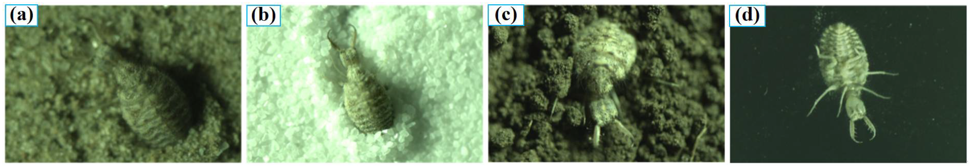
Abstract
:1. Introduction
2. Theoretical and Computational Models
2.1. Theoretical Model Establishment Method
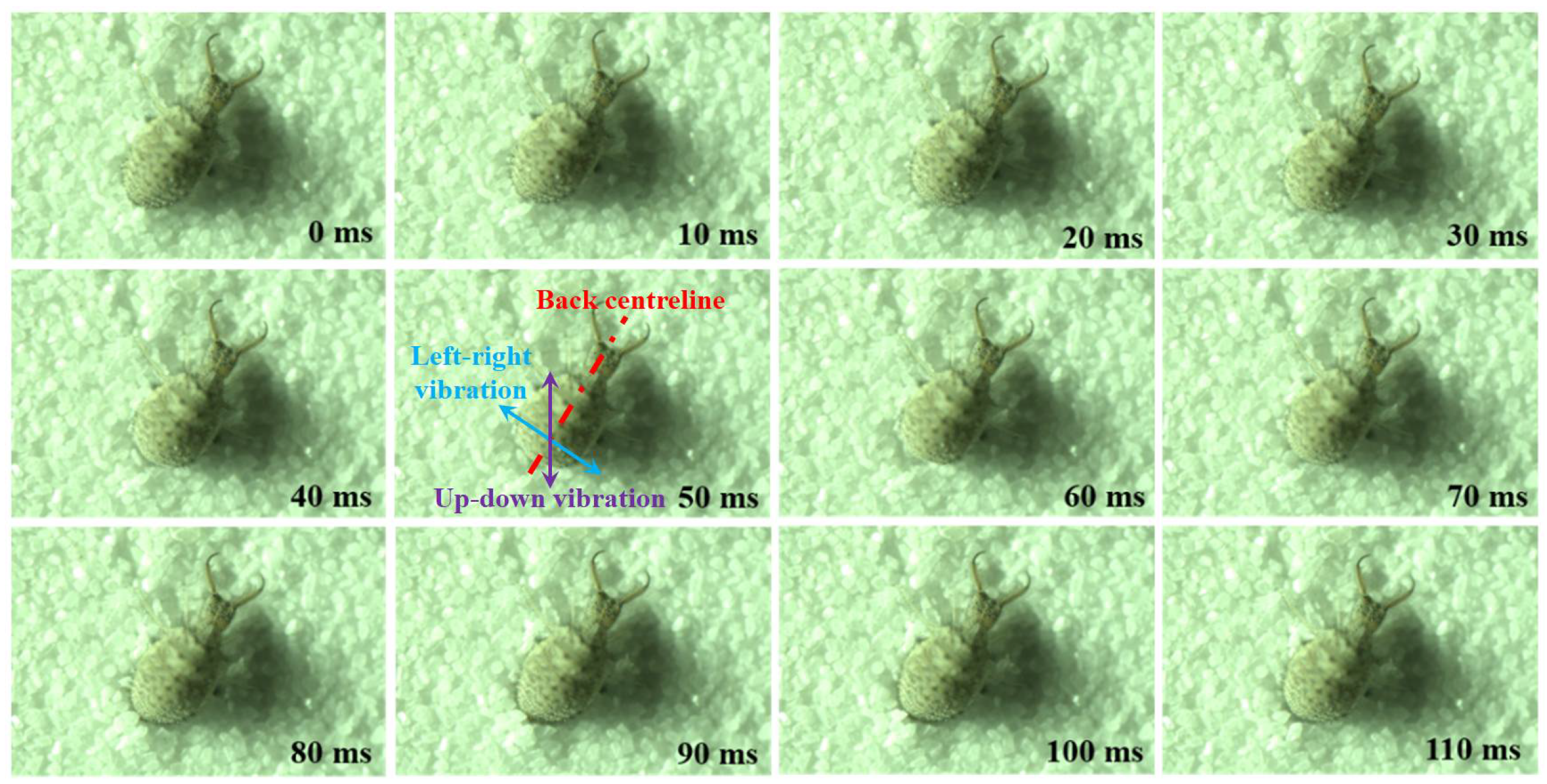
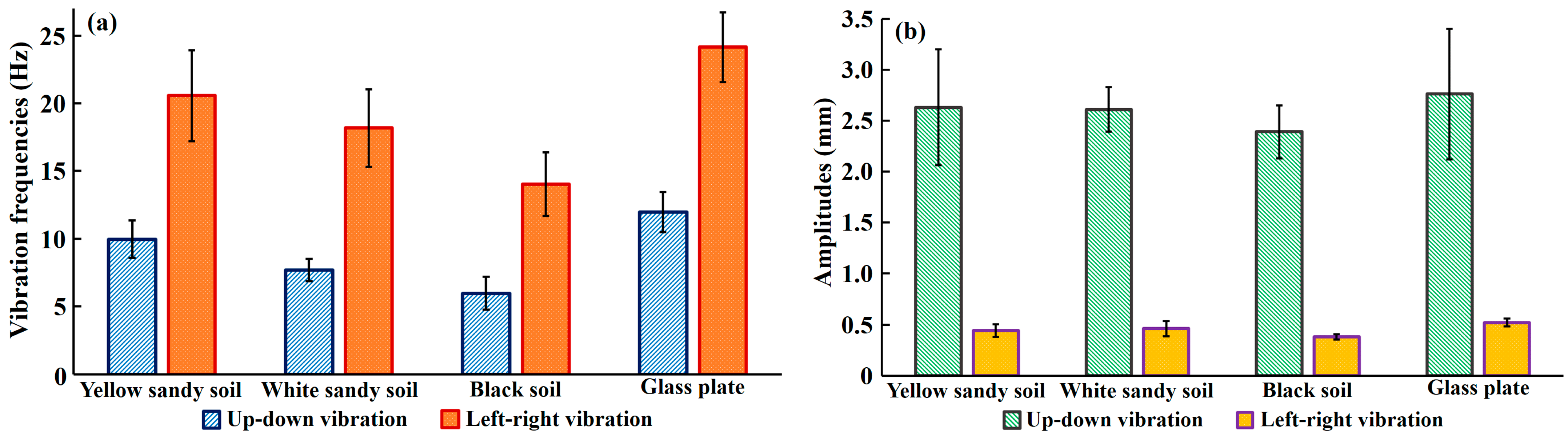
2.2. Antlions Vibration Digging Feature Acquisition
2.3. Principle and Application of Antlions Digging Resistance Reduction
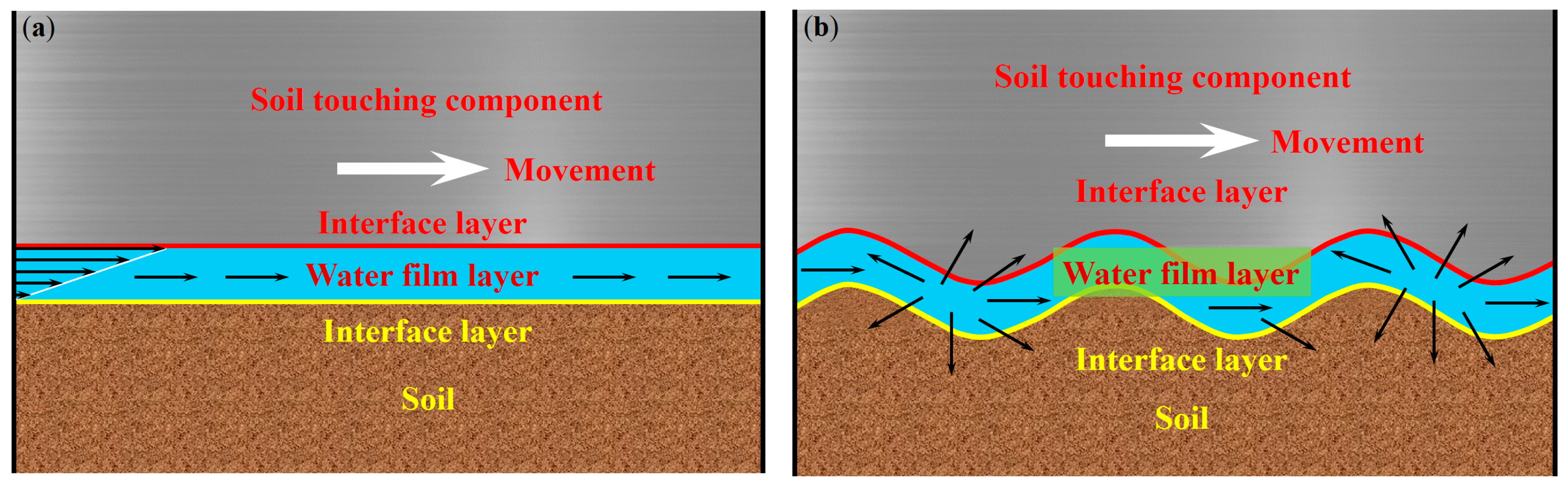
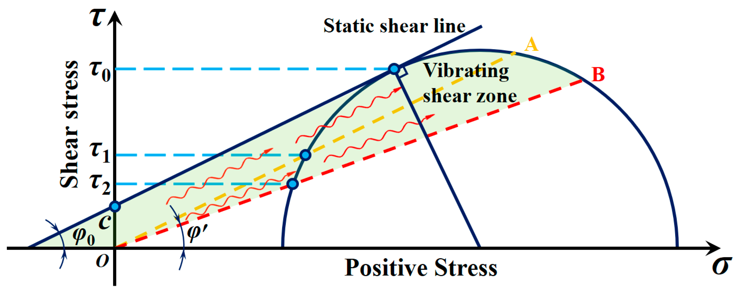
2.3.1. Non-Smooth Surfaces and Vibration Resistance Reduction Mechanism
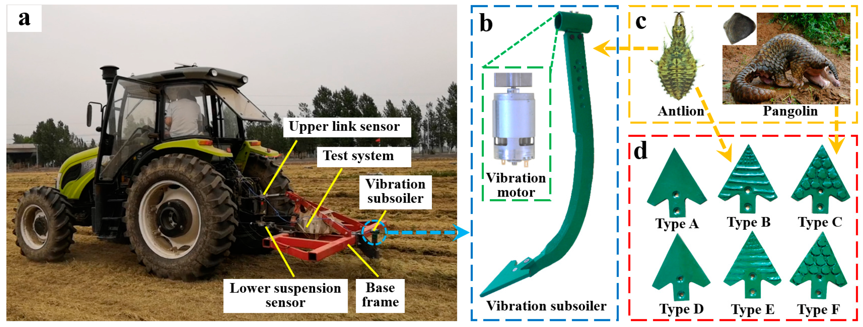
2.3.2. Bionic Drag Reduction Subsoiler Design
3. Field Experiment
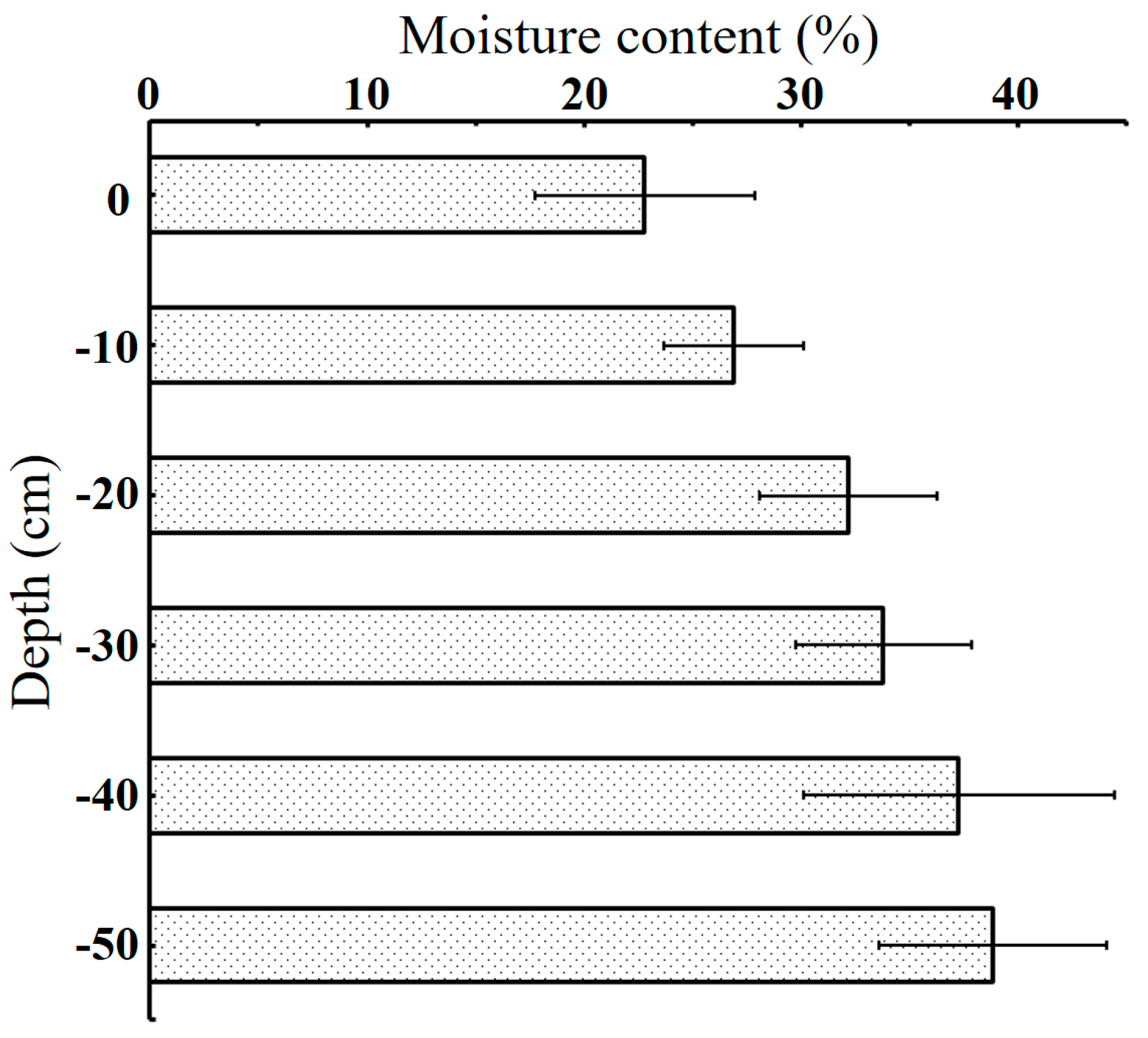
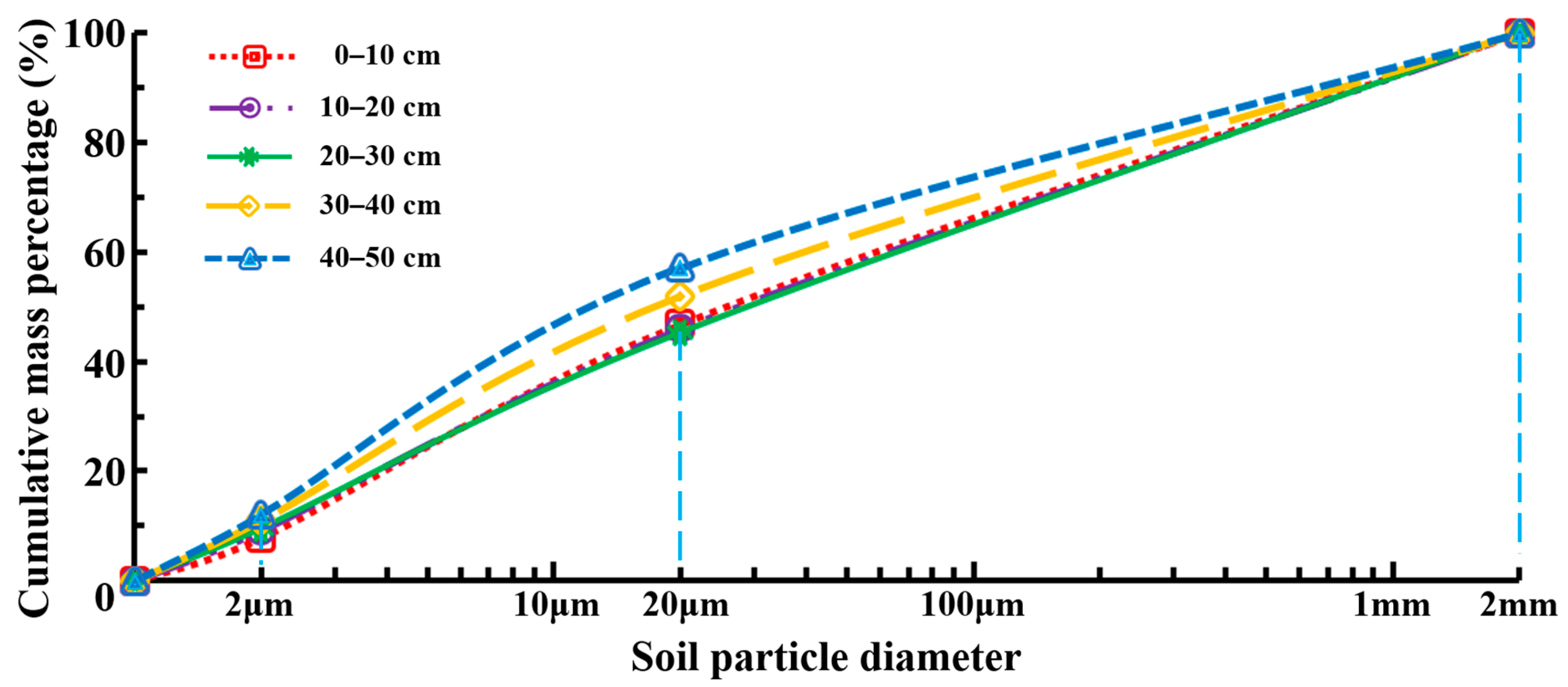
3.1. Soil Testing
3.2. Experimental Testing
3.3. Measured Values
3.3.1. Subsoiling Resistance
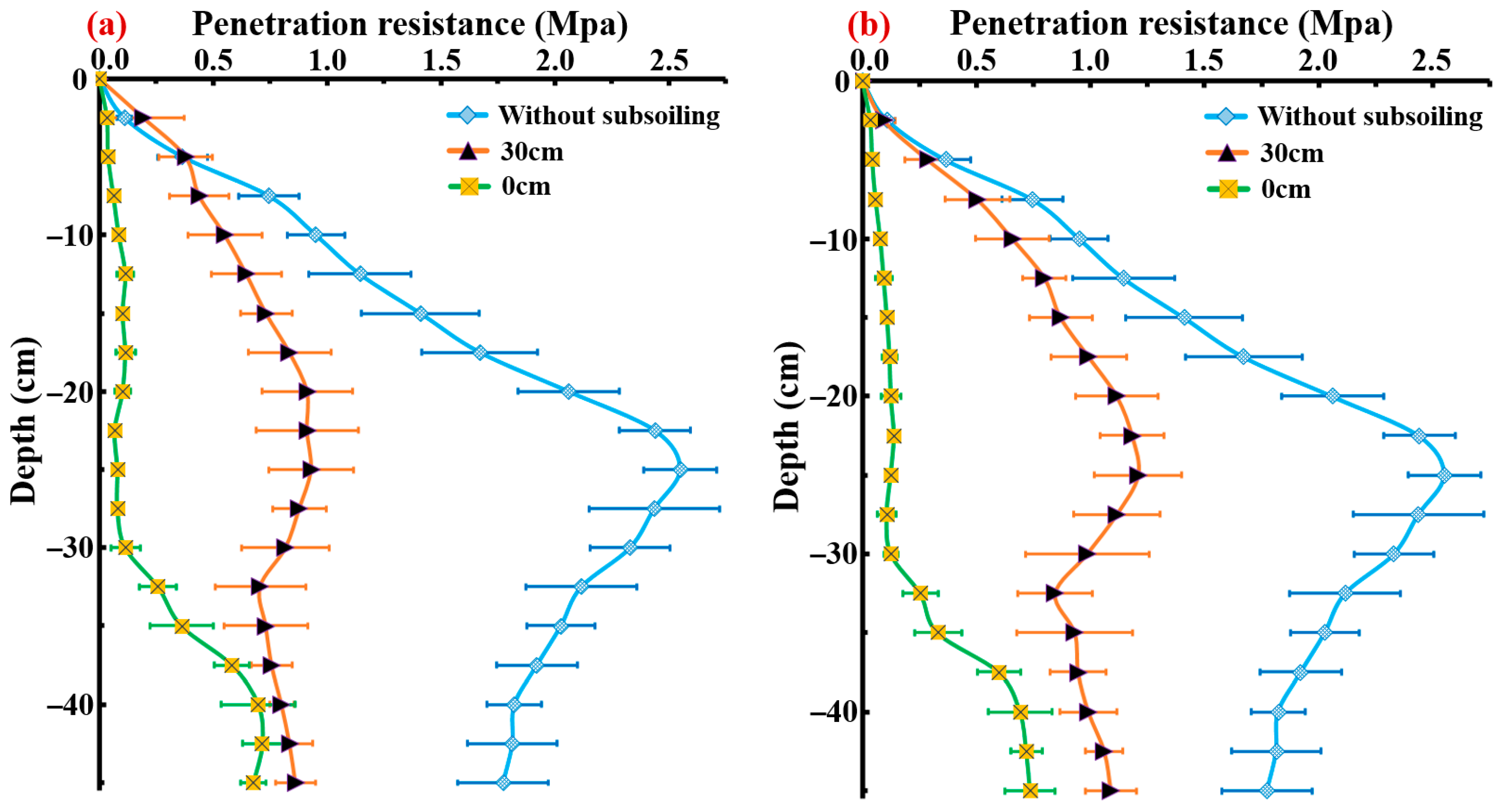
3.3.2. Soil Firmness
4. Results and Discussion
4.1. Analysis of the Subsoiling Resistance
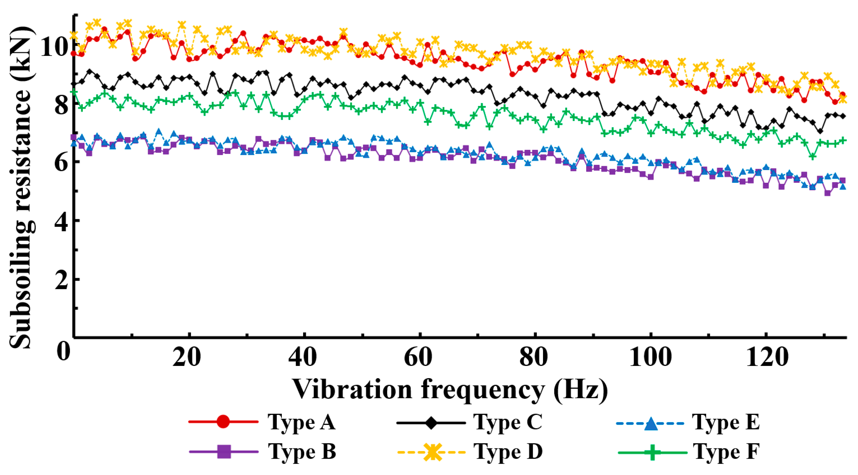
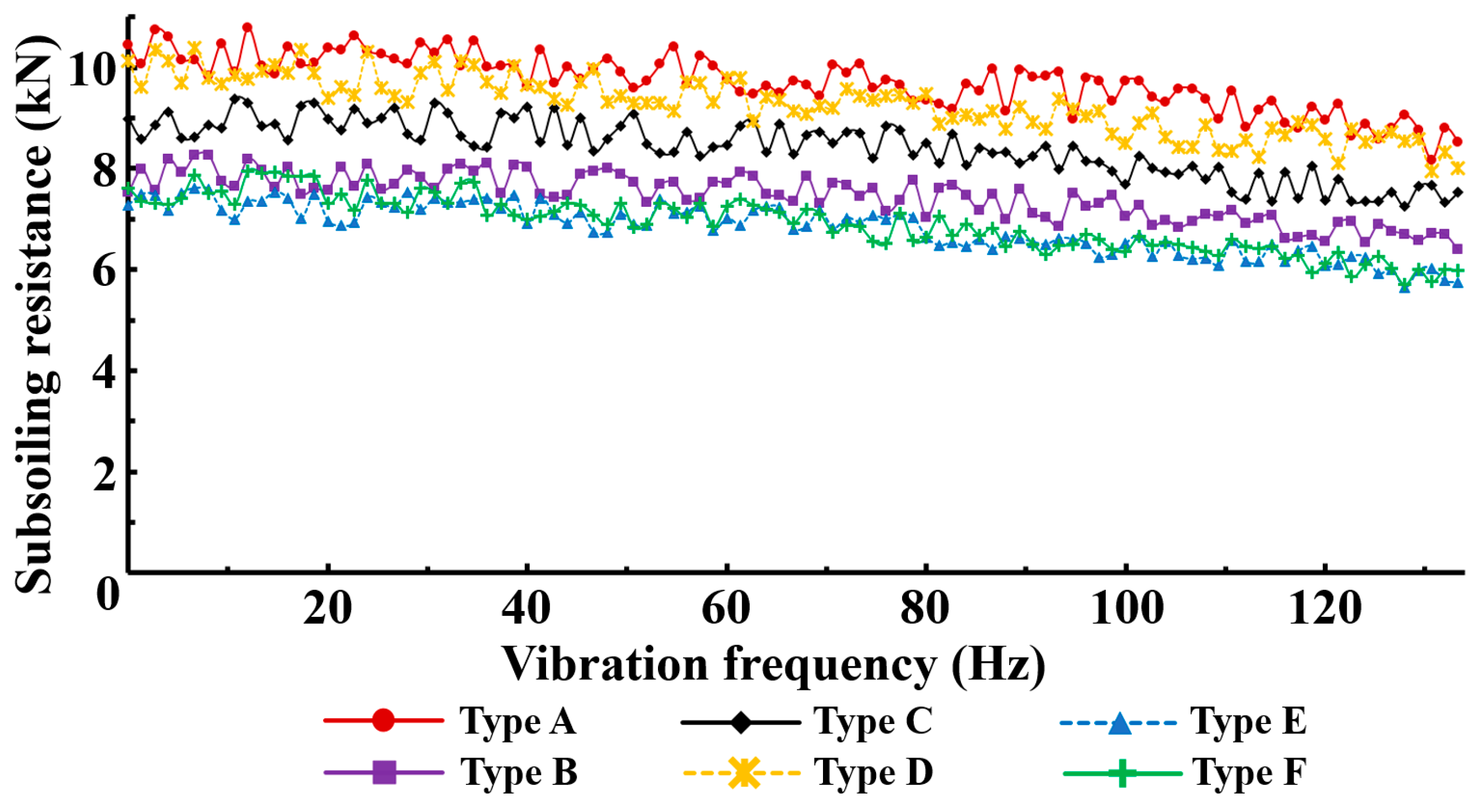
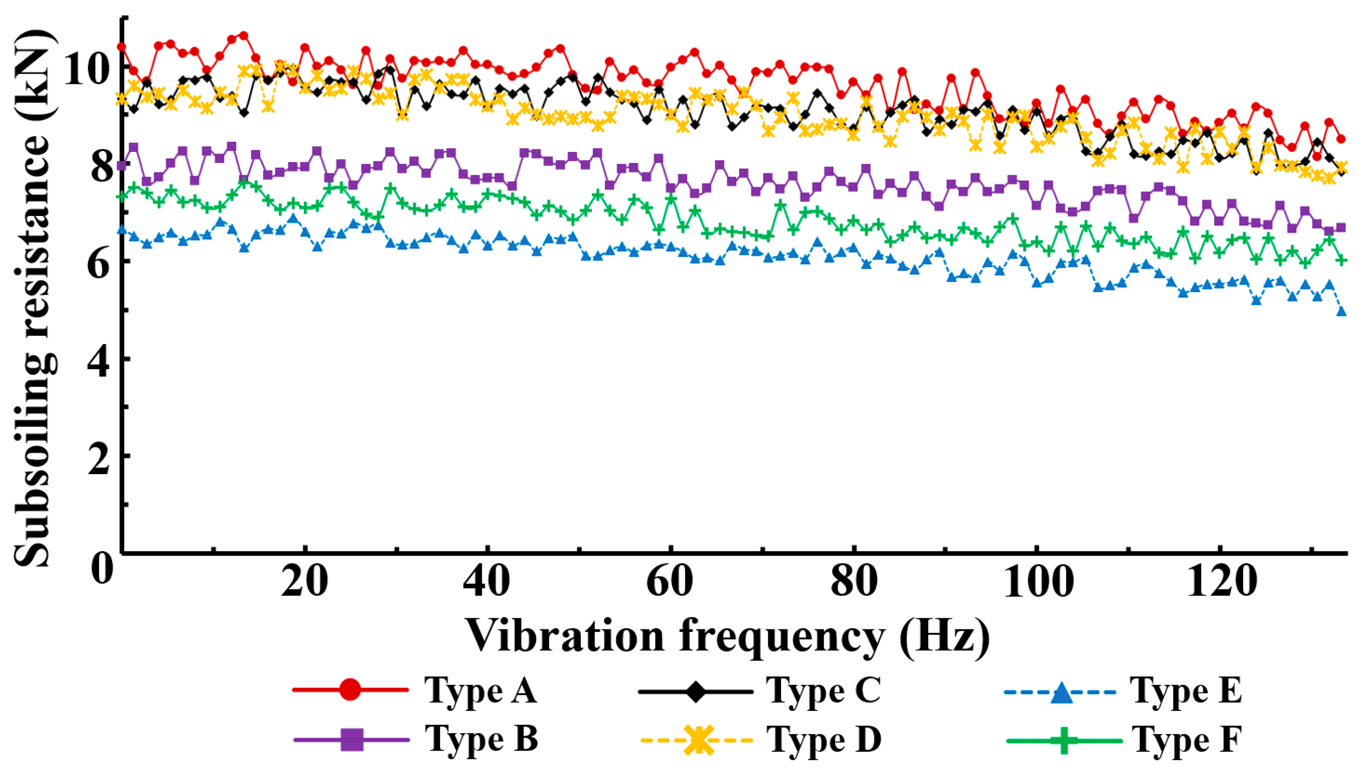
4.1.1. The Effect of Vibration Frequency on Subsoiling Resistance
4.1.2. The Effect of Subsoiler Tip Type on Subsoiling Resistance
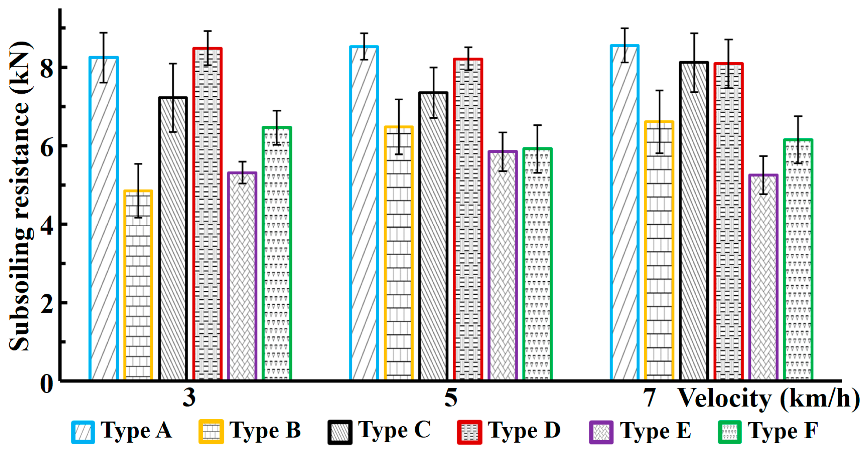
4.1.3. The Effect of Operation Speed on Subsoiling Resistance
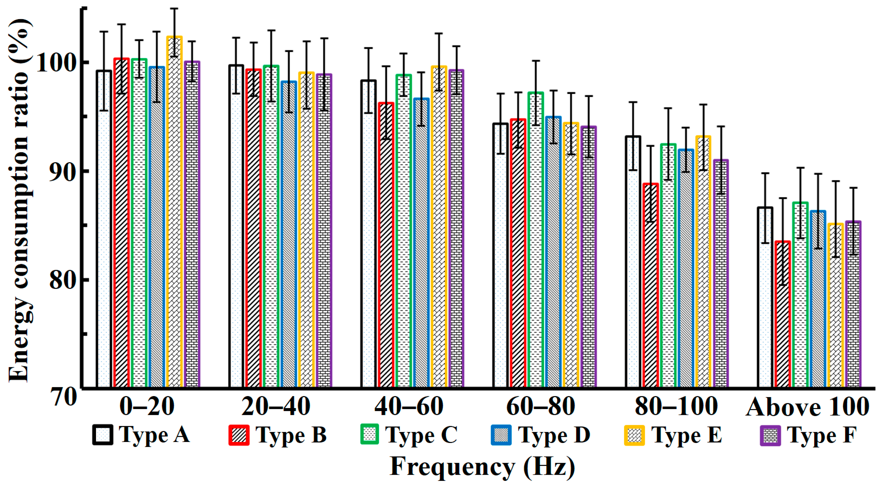
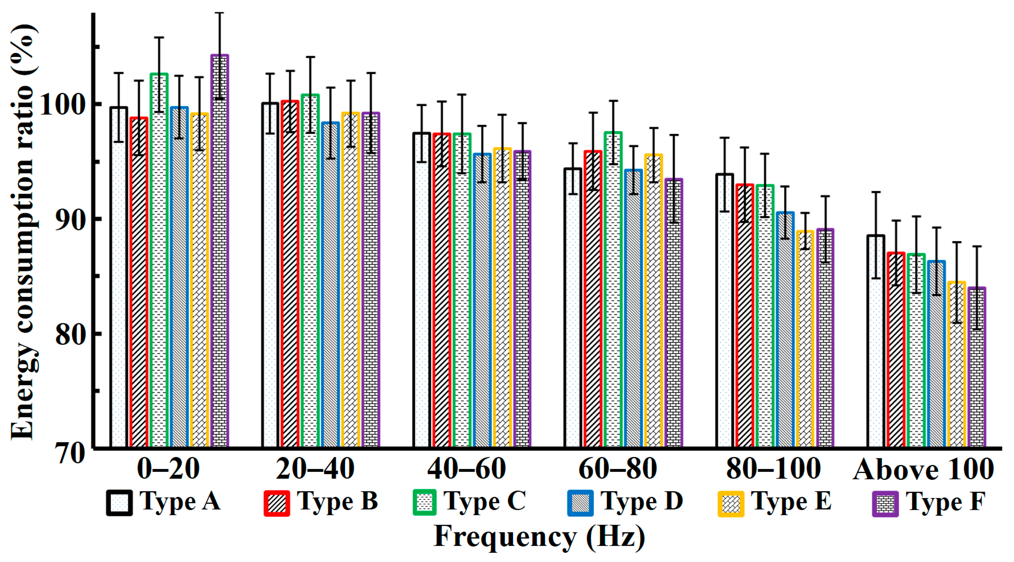
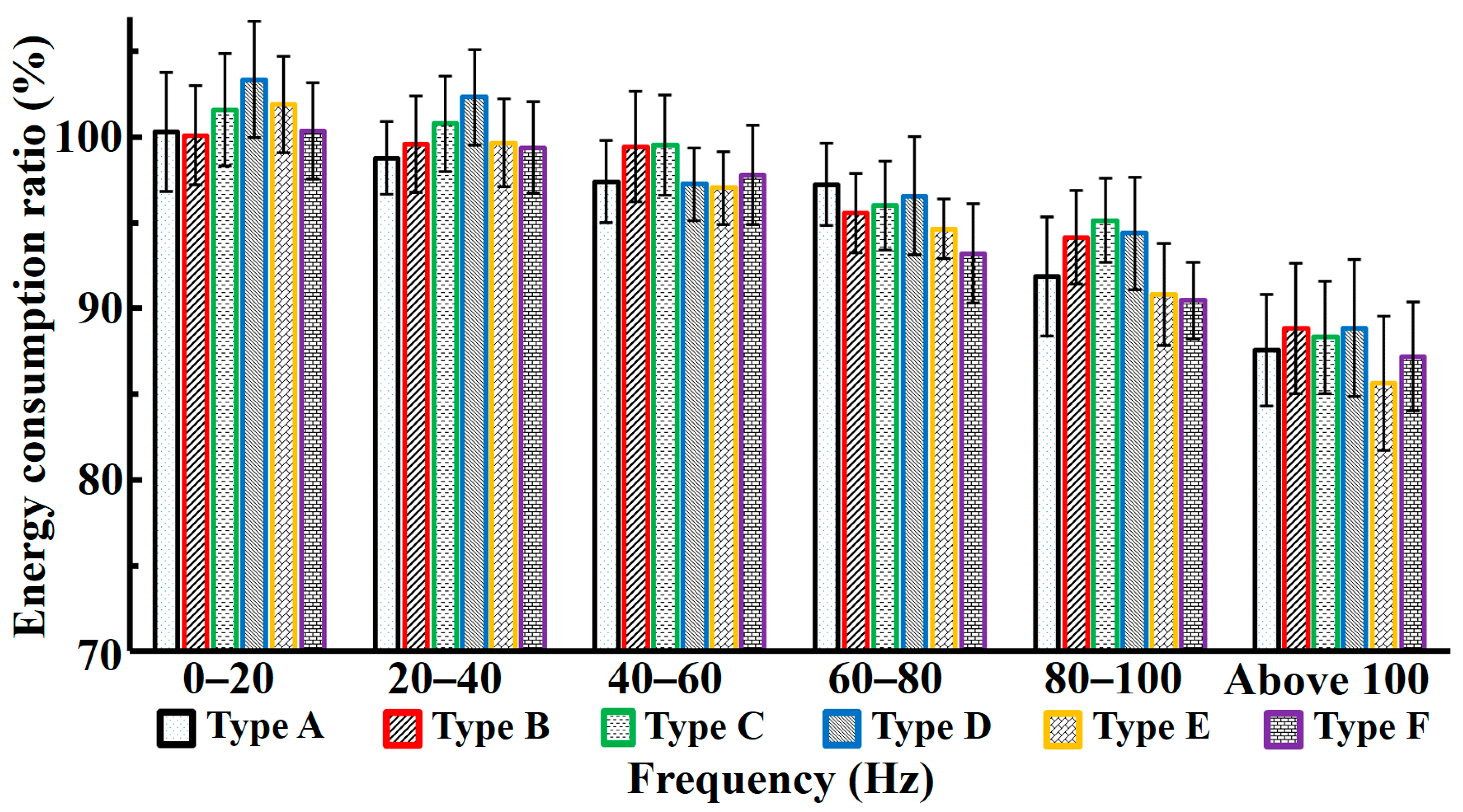
4.2. Energy Consumption Analysis of Forced Vibration Subsoiling
4.3. Changes of Soil Firmness before and after Subsoiling
5. Conclusions
Author Contributions
Funding
Conflicts of Interest
References
- Yue, L.; Wang, Y.; Wang, L.; Yao, S.; Cong, C.; Ren, L.; Zhang, B. Impacts of soil compaction and historical soybean variety growth on soil macropore structure. Soil Tillage Res. 2021, 214, 105166. [Google Scholar] [CrossRef]
- Cherubin, M.R.; Franchi, M.R.A.; Lima, R.P.; Moraes, M.T.; Luz, F.B. Sugarcane straw effects on soil compaction susceptibility. Soil Tillage Res. 2021, 212, 105066. [Google Scholar] [CrossRef]
- Forgó, Z.; Tolvaly-Roșca, F.; Pásztor, J.; Kovari, A. Energy Consumption Evaluation of Active Tillage Machines Using Dynamic Modelling. Appl. Sci. 2021, 11, 6240. [Google Scholar] [CrossRef]
- Schneider, F.; Don, A.; Hennings, I.; Schmittmann, O.; Seidel, S.J. The effect of deep tillage on crop yield—What do we really know? Soil Tillage Res. 2017, 174, 193–204. [Google Scholar] [CrossRef]
- Zhang, Q.; Yu, L.L.; Jia, H.L.; Liu, X.J.; Zhang, L. Design and Experiments of a Bionic Hook-Shape Subsoiler. Appl. Mech. Mater. 2013, 461, 50–56. [Google Scholar] [CrossRef]
- Orzech, K.; Załuski, D. Chemical properties of soil and occurrence of earthworms in soil in response to soil compaction and different soil tillage in cereals. J. Elem. 2020, 25, 153–168. [Google Scholar] [CrossRef]
- Li, H.; Zhang, Y.; Zhang, Q.; Ahmad, N.; Liu, P.; Wang, R.; Li, J.; Wang, X. Converting continuous cropping to rotation including subsoiling improves crop yield and prevents soil water deficit: A 12-yr in-situ study in the Loess Plateau, China. Agric. Water Manag. 2021, 256, 107062. [Google Scholar] [CrossRef]
- Lal, R. Minimum Tillage Systems; Lewis Publishers: London, UK, 1994. [Google Scholar]
- Wang, Y.; Li, N.; Ma, Y.; Tong, J.; Pfleging, W.; Sun, J. Field experiments evaluating a biomimetic shark-inspired (BioS) subsoiler for tillage resistance reduction. Soil Tillage Res. 2020, 196, 104432. [Google Scholar] [CrossRef]
- França, J.S.; Reicher, J.M.; Holthusen, D.; Rodrigues, M.F.; Araújo, E.F. Subsoiling and mechanical hole-drilling tillage effects on soil physical properties and initial growth of eucalyptus after eucalyptus on steeplands. Soil Tillage Res. 2021, 207, 104860. [Google Scholar] [CrossRef]
- Wang, H.; Bai, W.; Han, W.; Song, J.; Lv, G. Effect of subsoiling on soil properties and winter wheat grain yield. Soil Use Manag. 2019, 35, 643–652. [Google Scholar] [CrossRef]
- Zhang, X.C.; Guo, J.; Ma, Y.F.; Yu, X.F.; Hou, H.Z.; Wang, H.L.; Fang, Y.J.; Tang, Y.F. Effects of vertical rotary subsoiling with plastic mulching on soil water availability and potato yield on a semiarid Loess plateau, China. Soil Tillage Res. 2020, 199, 104591. [Google Scholar] [CrossRef]
- Zhang, Y.; Wang, S.; Wang, H.; Wang, R.; Wang, X.; Li, J. Crop yield and soil properties of dryland winter wheat-spring maize rotation in response to 10-year fertilization and conservation tillage practices on the Loess Plateau. Field Crop Res. 2018, 225, 170–179. [Google Scholar] [CrossRef]
- Scarpare, F.V.; Quirijn, D.J.V.L.; De, C.L.; Pires, R.C.M.; Ruiz-Corrêa, S.T.; Bezerra, A.H.F.; Gava, G.J.C.; Dias, C.T.S. Tillage effects on soil physical condition and root growth associated with sugarcane water availability. Soil Tillage Res. 2019, 187, 110–118. [Google Scholar] [CrossRef]
- Wang, Y.; Osman, A.; Zhang, D.; Yang, L.; Cui, T.; Zhong, X. Optimized design and field experiment of a staggered vibrating subsoiler for conservation tillage. Int. J. Agric. Biol. Eng. 2019, 12, 59–65. [Google Scholar] [CrossRef]
- Sun, J.; Wang, Y.; Ma, Y.; Tong, J.; Zhang, Z. DEM simulation of bionic subsoilers (tillage depth > 40 cm) with drag reduction and lower soil disturbance characteristics. Adv. Eng. Softw. 2018, 119, 30–37. [Google Scholar] [CrossRef]
- Ma, X.; Wang, S.; Wang, H. Vibration Soil Crushing Mechanism of Self-excited Vibration Subsoiler in Coastal Area. J. Coast. Res. 2020, 103, 426–430. [Google Scholar] [CrossRef]
- Li, J.; Jiang, X.; Ma, Y.; Tong, J.; Hu, B. Bionic Design of a Potato Digging Shovel with Drag Reduction Based on the Discrete Element Method (DEM) in Clay Soil. Appl. Sci. 2020, 10, 7096. [Google Scholar] [CrossRef]
- Wang, Y.; Xue, W.; Ma, Y.; Tong, J.; Liu, X.; Sun, J. DEM and soil bin study on a biomimetic disc furrow opener. Comput. Electron. Agric. 2019, 156, 209–216. [Google Scholar] [CrossRef]
- Sun, J.; Wang, Y.; Zhang, S.; Ma, Y.; Tong, J.; Zhang, Z. The mechanism of resistance-reducing/anti-adhesion and its application on biomimetic disc furrow opener. Math. Biosci. Eng. 2020, 17, 4657–4677. [Google Scholar] [CrossRef]
- Wang, Y.; Zhang, D.; Yang, L.; Cui, T.; Jing, H.; Zhong, X. Modeling the interaction of soil and a vibrating subsoiler using the discrete element method. Comput. Electron. Agric. 2020, 174, 105518. [Google Scholar] [CrossRef]
- Hilal, Y.Y.; Al-rajabo, S.A.J.; Dahham, G.A. The effects of vibrating wings subsoiler plow on driver’s seat of agricultural tractors and mechanization performance. Soil Tillage Res. 2021, 205, 104806. [Google Scholar] [CrossRef]
- Zheng, K.; McHugh, A.; Li, H.; Wang, Q.; Lu, C.; Hu, H.; Liu, W.; Zhang, Z.; Liu, P.; He, J. Design and experiment of anti-vibrating and anti-wrapping rotary components for subsoiler cum rotary tiller. Int. J. Agric. Biol. 2019, 12, 47–55. [Google Scholar] [CrossRef]
- Wang, Y.; Zhang, D.; Yang, L.; Cui, T.; Zhang, W.; Qi, B.; Li, Y.; Zhong, X. Field performance of an electric–hydraulic control system for vibrating subsoiler with flexible tines. Comput. Electron. Agric. 2020, 172, 105377. [Google Scholar] [CrossRef]
- Zhang, X.; Wang, C.; Chen, Z.; Zeng, Z. Design and experiment of a bionic vibratory subsoiler for banana fields in southern China. Int. J. Agric. Biol. 2016, 9, 75–83. [Google Scholar]
- Ma, X.; Wang, S. Design and Study on Vibration Characteristics of Self-excited Vibration Layered Subsoiler for Coastal Soil. J. Coastal Res. 2020, 103, 318–322. [Google Scholar] [CrossRef]
- Büsse, S.; Büscher, T.H.; Gorb, S.N.; Stutz, H.H. Sand-throwing behaviour in pit-building antlion larvae: Insights from finite-element modelling. J. R. Soc. Interface 2021, 18, 1742–5662. [Google Scholar] [CrossRef]
- Farji-Brener, A.G.; Juncosa-Polzella, A.S.; Tejada, D.M.; Centeno-Alvarado, D.; Hernández-Soto, M.; Soto-Huaira, M.; Gutiérrez-Cruz, S. Disadvantages of living in a populous neighborhood for sit-and-wait predators: Competition for space reduces pit-trap size in antlion larvae. Ethology 2020, 126, 1031–1037. [Google Scholar] [CrossRef]
- Miler, K.; Yahya, B.; Czarnoleski, M. Substrate moisture, particle size and temperature preferences of trap-building larvae of sympatric antlions and wormlions from the rainforest of Borneo. Ecol. Entomol. 2019, 44, 488–493. [Google Scholar] [CrossRef]
- Tong, J.; Wu, B.; Song, Z.; Gao, Z.; Sun, J.; Ma, Y.; Zhuang, J. Research on the Drag Reduction Mechanism of Antlion (Myrmeleon Sagax) Larvae Nonsmooth Structural Surface. Microsc. Res. Tech. 2020, 83, 338–344. [Google Scholar] [CrossRef]
- Wu, A.X.; Sun, Y.Z.; Liu, X.P. Basic Physical and Mechanical Properties of Granules; Metallurgical Industry Press: Beijing, China, 2002. [Google Scholar]
- Ren, L.Q. Soil Adhesion Mechanics; Machinery Industry Press: Beijing, China, 2011. [Google Scholar]
- Rafiei Renani, H.; Martin, C.D. Slope Stability Analysis using Equivalent Mohr–Coulomb and Hoek–Brown criteria. Rock Mech. Rock Eng. 2020, 53, 13–21. [Google Scholar] [CrossRef]
- Moran, D.A.; Pantelides, C.P. Elliptical and circular FRP-confined concrete sections: A Mohr–Coulomb analytical model. Int. J. Solids Struct. 2012, 49, 881–898. [Google Scholar] [CrossRef] [Green Version]
- Wu, B.G. Research of Forced Vibration and Structure Coupling Biomimetic Subsoiler for Energy Saving and Drag Reduction. Ph.D. Thesis, Jilin University, Cangchun, China, 2020. [Google Scholar]
- FAO, IUSS. World Reference Base for Soil Resources 2014. International Soil Classification System for Naming Soils and Creating Legends for Soil Maps; FAO, IUSS: Rome, Italy, 2015; p. 203. [Google Scholar]


Publisher’s Note: MDPI stays neutral with regard to jurisdictional claims in published maps and institutional affiliations. |
© 2021 by the authors. Licensee MDPI, Basel, Switzerland. This article is an open access article distributed under the terms and conditions of the Creative Commons Attribution (CC BY) license (https://creativecommons.org/licenses/by/4.0/).
Share and Cite
Zhou, D.; Hou, P.; Xin, Y.; Wu, B.; Tong, J.; Yu, H.; Qi, J.; Zhang, J.; Zhang, Q. Resistance and Consumption Reduction Mechanism of Bionic Vibration and Verification of Field Subsoiling Experiment. Appl. Sci. 2021, 11, 10480. https://0-doi-org.brum.beds.ac.uk/10.3390/app112110480
Zhou D, Hou P, Xin Y, Wu B, Tong J, Yu H, Qi J, Zhang J, Zhang Q. Resistance and Consumption Reduction Mechanism of Bionic Vibration and Verification of Field Subsoiling Experiment. Applied Sciences. 2021; 11(21):10480. https://0-doi-org.brum.beds.ac.uk/10.3390/app112110480
Chicago/Turabian StyleZhou, Deyi, Pengfei Hou, Yuelin Xin, Baoguang Wu, Jin Tong, Haiye Yu, Jiangtao Qi, Jinsong Zhang, and Qiang Zhang. 2021. "Resistance and Consumption Reduction Mechanism of Bionic Vibration and Verification of Field Subsoiling Experiment" Applied Sciences 11, no. 21: 10480. https://0-doi-org.brum.beds.ac.uk/10.3390/app112110480