Article

Characterizing the Mechanical Performance of a Bare-Metal Stent with an Auxetic Cell Geometry

by
Sukhwinder K. Bhullar
1,2,3,4,*,†,
Huseyin Lekesiz
1,
Ahmet Abdullah Karaca
1,
Yonghyun Cho
2,3,4,
Stephanie Michelle Willerth
2,3,4 and
Martin B. G. Jun
2,3,4,5
1
Department of Mechanical Engineering, Bursa Technical University, 16310 Bursa, Turkey
2
Department of Mechanical Engineering, University of Victoria, Victoria, BC V8W 2Y2, Canada
3
Division of Medical Sciences, University of Victoria, Victoria, BC V8W 2Y2, Canada
4
Centre for Advanced Materials and Technology, University of Victoria, Victoria, BC V8W 2Y2, Canada
5
School of Mechanical Engineering, Purdue University, West Lafayette, IN 47907, USA
*
Author to whom correspondence should be addressed.
Current affiliation and address: Institute of Cardiovascular Sciences, St. Boniface Hospital Albrechtsen Research Centre, University of Manitoba, Winnipeg, MB R3T 2N2, Canada.
Submission received: 1 December 2021 / Revised: 1 January 2022 / Accepted: 10 January 2022 / Published: 17 January 2022

Abstract

:
This study develops and characterizes the distinctive mechanical features of a stainless-steel metal stent with a tailored structure. A high-precision femtosecond laser was used to micromachine a stent with re-entrant hexagonal (auxetic) cell geometry. We then characterized its mechanical behavior under various mechanical loadings using in vitro experiments and through finite element analysis. The stent properties, such as the higher capability of the stent to bear upon bending, exceptional advantage at elevated levels of twisting angles, and proper buckling, all ensured a preserved opening to maintain the blood flow. The outcomes of this preliminary study present a potential design for a stent with improved physiologically relevant mechanical conditions such as longitudinal contraction, radial strength, and migration of the stent.

1. Introduction

Diseases, including atherosclerosis, hypertension, diabetes, genetic defects, and aging, result in alterations in the mechanics of arteries, such as the development of artery blockage, contraction, twisting, elongation, tortuosity, kinking, and curving. These changes cause several cardiovascular diseases, such as coronary heart disease and peripheral artery disease, which reduce the ability of the heart to pump enough blood within the vessels and arteries, leading to heart failure. Coronary artery disease occurs from plaque build-up on an artery’s inner surface, which becomes significantly narrowed and blocked in advanced stages of the disease [1,2,3,4,5,6]. This process consisting of the hardening of the arteries is called atherosclerosis. About 17.6 million people in the United States suffer from narrow heart vessel disease, causing 450,000 deaths each year due to heart attacks caused by fully obstructed arteries.
Balloon angioplasty followed by the placement of a stent is the most common therapy used to open these blocked arteries [7,8,9,10,11]. This procedure utilizes a catheter to place a stent in blood vessels narrowed by plaque build-up. It was first introduced to reduce the risks of elastic recoiling and restenosis while strengthening the artery wall so it remains open [12]. The chances of restenosis reduced to 25% in stenting procedures while compared to angioplasty [13]. Early permanent metal stents were known as first-generation bare-metal stents. In 1986, the first metal stent was implanted into a human coronary artery. These bare metal stent almost eliminated the chances of an artery collapsing, but had other issues. Subsequently, first-generation drug-eluting, and second- and third-generation biodegradable polymer-based drug-eluting stents were developed [11,13,14,15,16,17,18,19,20,21,22]. Drug-eluting stents also reduced early and delayed complications with stenting, as well as restenosis rate by 80% [23]. Bioresorbable vascular scaffolds are also being developed. This category of stents disappears after treating diseased blood vessels by creating a thin and all-natural cell layer inside the artery [24]. In this second-and third-generation drug-eluting stent era, a large body of evidence has demonstrated a significant improvement in coronary stent safety and efficacy in most clinical situations [25]. However, the bare-metal stent (BMS) still remains an option for percutaneous coronary intervention (PCI). Particularly for patients who cannot complete the recommended duration of dual antiplatelet therapy because of noncompliance, the avoidance of cardiac surgery, or increased risk for bleeding, especially if the accused lesion is present in large coronary vessels, PCI is recommended. It is suggested for patients who are at high risk of bleeding that the duration of dual antiplatelet therapy be reduced to a minimum of one month with BMS placement or three months with a drug-eluting stent [26]. These first-generation BMS are considered most effective in preventing acute occlusion and reducing late restenosis, and 20% of patients in the USA and 19.6% of patients in Australia are treated with BMS implantation every year [12,13,27,28,29]. Over the past 40 years, research and clinical trials in this regard have resulted in different stent designs comprising diverse materials include metals, metal alloys, platinum, polymer, plastics, coated or uncoated in balloon-expandable and self-expandable forms.
Depending on the appropriate choice of a stent depends on the patient’s symptoms—the local deposition of plaque, fatty substances, and the potential side effects [12,18,30,31]. During the last decade, the quantity and quality of life of patients suffering from heart attacks due to arterial blockages have improved immensely through stent implantation interventions, which are a suitable replacement for surgery. However, there are still patients suffering from stent failure, thrombosis, or restenosis. The inefficiency of stent designs is causing the high failure rate of arterial stenting [27,32,33,34,35,36]. Thus, stents still have significant research potential for optimization despite being used clinically for decades. Stent optimization can be accomplished based on the design, choice of materials, fabrication method, surface functionalization, and implantation procedure [37].
Since the mechanical behaviors of the stent are of critical importance for efficient functional recovery of blood vessels, auxetic designs have recently been proposed for mechanically tunable stents [38,39,40,41,42] to enhance the radial expansion ability while reducing the axial expansion [43,44,45,46]. Briefly, compared to most conventional materials, auxetics are mechanical metamaterials artificially designed to exhibit negative Poisson’s ratios that contract in transverse directions upon being compressed uniaxially. Auxetics presents enhanced mechanical properties such as indentation resistance, fracture toughness, and shear stiffness, which greatly facilitate a range of applications, including biomedical applications [47,48,49,50]. Different auxetic designs, including chiral, rigid node rotational, re-entrant, and elastic instability for stent designs, have been presented a potential for optimization between strut thickness, mechanical capacity, and deformation ability [38,39,40,51,52,53,54,55,56,57,58,59]. Studies also consider that arterial endothelium subjected to both wall shear stresses and a cyclic circumferential strain due to pulsatile blood flow exhibits concurrent axial and transverse expansion (contraction) similarly to an auxetic structure [59]. Thus, an auxetic stent could likely better integrate with native tissues. In this regard, plastic and polymer auxetic stents were evaluated mechanically, numerically, and analytically [32,33,60,61]. To the authors’ knowledge, bare metal auxetic design stents for mechanical performance have not been studied in the literature. Thus, in our paper, we have presented a 316 L stainless steel stent with an auxetic cell geometry fabricated with high precision femtosecond micromachining and laser welding. Stents are a permanent implants and according, they experience various mechanical loadings such as bending, longitudinal compression, buckling, and torsion on the implantation site either in delivery or implantation (Figure 1) from the pulsation of the heart or body movement or pressures of the surrounding vessels and blood flow [8,62,63,64,65,66,67]. Thus, here we performed analysis of the mechanical capacity of the stent under mechanical loadings (Figure 1) combined with in vitro mechanical/finite element analysis (FEA) to understand the performance of this design. The novelty of the paper not just lies in studying extensive mechanical loadings representing realistic conditions, but also in the production methodology of the stent produced from stainless steel sheets by femtosecond laser cutting. This combination brings different mechanical aspects compared to the auxetic structures studied in the literature. Some of the mechanical issues such as stability of struts were already discussed in the author’s previous work for auxetic plates [51], but this work extends these discussions for the tube form. Mechanical evaluations are conducted for both experimental and FE simulations to verify the assumptions in mechanical modeling in simulations. This study focused on evaluating the mechanical potential of cylindrical auxetic stent design, which was modeled and analyzed in the cylindrical state as the final shape produced by laser cutting and welding, and was not crimped nor expanded, which should be noted.

2. Materials and Methods

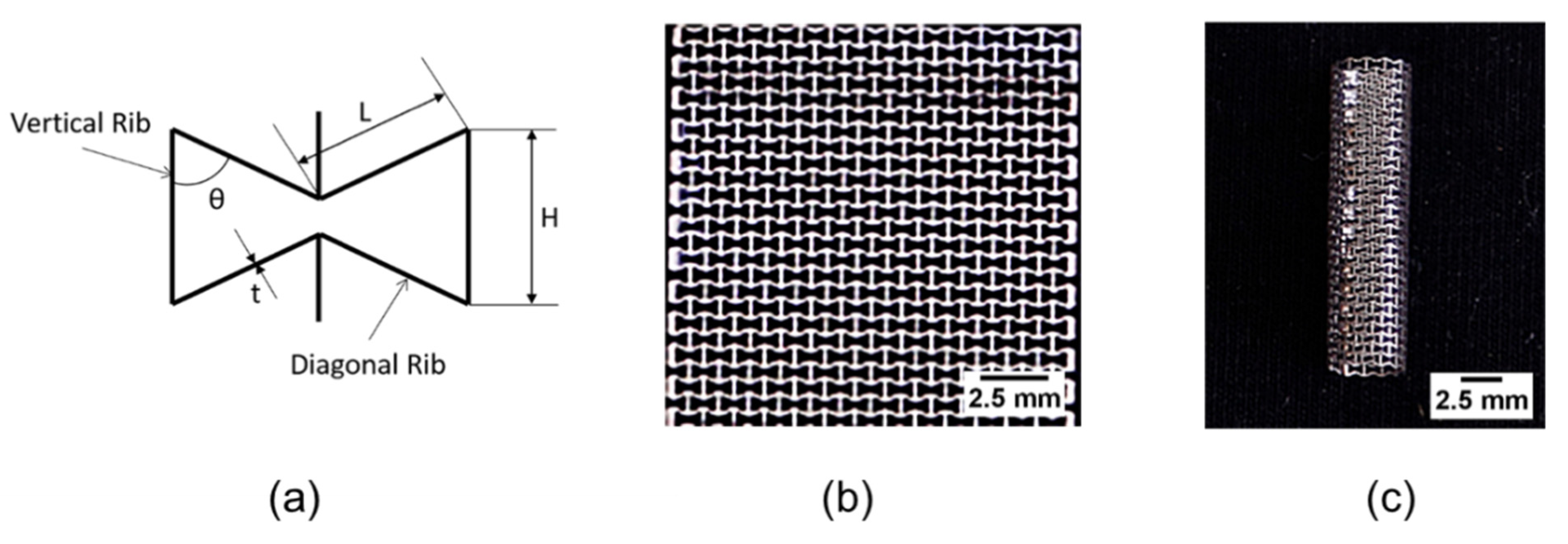
2.1. Production of the Stents

In this study, stents were produced in two stages: First, 316 L (Sigma Aldrich, St. Louis, MO, USA) stainless steel sheets with 100 μm thickness were cut by femtosecond laser using a cut-out geometry. In the second step, tailored plates were rolled into a cylinder and laser spot welded at the joining line. For cut-out geometry, an optimized unit-cell geometry was determined based on previous work by Lekesiz et al. (2017) in [51], shown in Figure 2a. Here, the dimensions were: height of vertical rib (H) is 0.69 mm; the length of diagonal rib (L) 0.56 mm; the angle between vertical and diagonal ribs (θ) 66.35 degrees and rib thickness (t) 0.1 mm. These dimensions were determined to prevent out-of-plane buckling of struts and provide sufficient radial and longitudinal stiffness. After preparing unit-cell geometry in SolidWorks design software, Victoria, Canada, (Figure 2a), the geometrical pattern was machined on stainless steel 316 L sheets (Figure 2b) using femtosecond laser cut-out. Tailoring the auxetic design was made by using a Ti:Sapphire femtosecond laser with 1 kHz repetition rate, 120 vfs pulse duration, and 800 nm central wavelength. The laser beam was directed into a microscope, and then it was focused by 20× objective lenses with 0.42 numerical aperture (Mitutoyo, Victoria, Canada). The beam diameter was reduced to 3 mm using an iris diaphragm to achieve a thin cut-out. Turning on and off the laser beam was made possible by a computer-controlled electronic shutter. The final micromachined width and length of the plates were 15 mm and 20 mm, respectively. These plates were rolled and then were laser welded to fabricate the stent (Figure 2c). Thus, the diameter of the produced stents was approximately 5 mm (4.77 mm), the length is 20 mm.

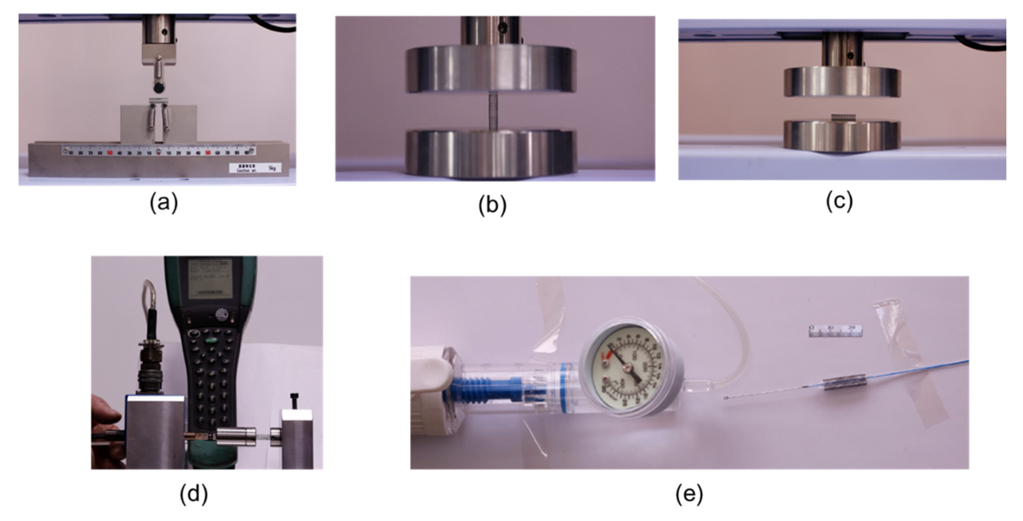
2.2. Mechanical Testings

Since stents undergo various combined loadings during both insertion and in-service conditions, loadings, including three-point bending, torsion, longitudinal buckling, and radial expansion, were tested with a Shimadzu universal tester with 1 kN maximum capacity in Bursa Technical University’s mechanical engineering laboratories using procedures as explained below.

2.2.1. Three-Point Bending

As shown in Figure 3a, three samples were tested under three-point bending conditions with a 12 mm span between 4 mm-diameter supporting pins and a 10 mm-diameter loading pin located in the middle of the sample., Force-displacement values, linear, nonlinear behaviors, flexibility on the linear region were plotted and evaluated graphically by applying a cross-head speed of 3 mm/min and force-displacement values saved for every 0.02 s. The test recorded on video and deformed shape and points on force-displacement graphs coincided for proper mechanical evaluation. The test was terminated when an almost complete fold was observed around 6.8 mm.

2.2.2. Radial Strength

Three stents were compressed between two compression plates (Figure 3c) for radial strength testing. The specimen was placed laterally on the bottom plate. The cross-head speed of 3 mm/min (50 µm/s) for the upper plate was selected to avoid any dynamic effect and to create quasistatic conditions. The test was performed and continued until the stent became completely folded and total displacement reached 4.5 mm. Saved force and displacement values at every 0.02 s were depicted in force-displacement graphs to quantify physical changes during lateral compression. A similar method was employed for a longitudinal buckling until displacement reached 5 mm, by placing the specimen on the bottom plate vertically.

2.2.3. Torsion

For torsional loading, a custom-made apparatus consisting of a frame, torque sensor and fixators was designed as shown in Figure 3d. The main idea of the design was to hold the torque measurement sensor and fixators in a straight direction to apply torque on the axis of the stent. To measure rotation, an angleCrane®, Bursa, Turkey torque measurement sensor with 1% accuracy was used. With a moment arm attached to the torque sensor (Figure 3d), two stent specimens were twisted manually up to 200 degrees of rotation. Three millimeters of both ends of the stents were fixed to the torsional shafts using setting screws. With the help of a digital display attached to the sensor we took measurements. Values for torque and rotation angle captured simultaneously with a high-resolution camera (Canon® 5D Mark III, Bursa, Turkey). Deformations up to a point where cylindricality remained apparent, and complete irreversible warping of the stent were recorded. Torque versus twisting angles for both specimens were plotted on a graph to evaluate stages of deformation and failure.

2.2.4. Radial Expansion Testing

A balloon-catheter procedure was employed using the devices used in actual operations under in vitro conditions for radial expansion analysis. Pressure values were measured by pressure valve, while stent diameter and length changes were measured using a high-resolution camera (Canon® 5D Mark III) placed and fixed on a top angle. A length scale was taped near the stent and used as a reference for diameter and length measurements (Figure 3e). The pictures for the pressure valve and the stent were taken every second throughout the test to depict the pressure values versus stent diameter values and stent length values using image processing to characterize the auxetic stent radial expansion behavior. Tests terminated automatically when the pressure balloon was inflated.

2.3. Finite Element Analysis-Simulations
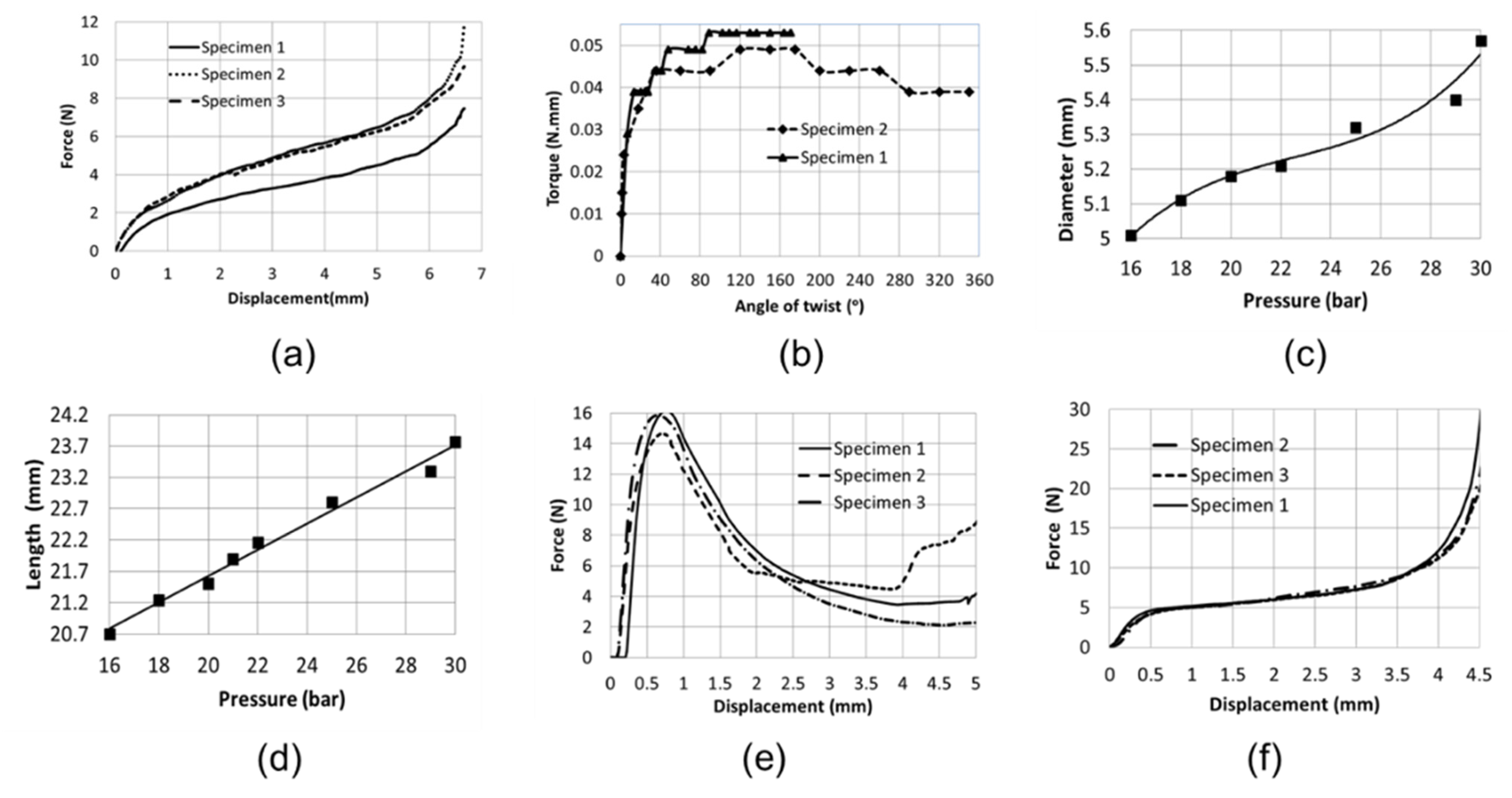
The simulations were conducted with finite element analysis (FEA) for the above-mentioned mechanical tests except for balloon expansion. The stent design (Figure 2c) created using SolidWorks®, Bursa, Turkey was exported to HyperMesh®, Bursa, Turkey for meshing. A quad-shape shell mesh with 100-micron thickness was defined, dividing each cell wall of the stent into two elements. In their previous work, Lekesiz et al. [51] demonstrated mesh convergence, and a comparison between tests and simulations for tensile testing validated that two-element over thickness provides high accuracy. Since the auxetic stent displayed a highly deformable structure and strain hardening, damaging, and failure stages involve material nonlinearities, implicit analysis was executed running simulations using RADIOSS®, Bursa, Turkey solver accompanied by HyperMesh. Tabulated piecewise linear and quadratic elastoplastic law (Law 36 in RADIOSS, Bursa, Turkey) for material and failure modeling and stress-strain data from tensile testing of the base material (316 L stainless steel strips) [51] was entered into the program to identify parameters in this law. Boundary conditions and loadings were determined based on testing conditions indicated in the previous section. Type 7 contact (a multipurpose contact in RADIOSS) between pins and stents was defined for the three-point bending simulations. Applying a downward imposed velocity of 3 mm/min to the top cylinders’ center analysis was conducted to the point where the loading pin touches supporting pins. Fixing one edge of the stent in all directions, then applying an imposed twist with 0.05 rad/s velocity to the other edge, torsion simulations were run. For longitudinal buckling and lateral compression, a rigid plate was modeled and placed flat on the top surface of the stent, and setting the bottom of the stent fixed in all directions, and imposed velocity of 3 mm/min defined for the rigid plate.

3. Results

Mechanical Testing: Displacement-force curves for longitudinal/lateral compression, three-point bending, longitudinal buckling, angle of twist versus torque curves for torsion, pressure versus diameter, and length for radial expansion are provided in Figure 4a–f.

3.1. Three-Point Bending

Force-displacement curves for all three specimens of auxetic stents under three-point bending in Figure 4a present a nonlinear behavior under bending loading. Two curves for specimens 2 and 3 match closely, while the curve for specimen 1 deviates with approximately 30% lower strength. However, all samples show a similar trend with a relatively stiff behavior for the first 0.5 mm displacement then softer afterwards and high stiffness again after 6 mm displacement where the stent completely folded and loading pin level coincides with the supporting pins. There was no any warping or wrinkling observed in the structure. Subsequently, the auxetic stent took the shape of a loading pin, whereas the portion outside the supporting span remained circular. That behavior is different from regular tubular structures without an auxetic pattern. Auxetic plates have shown a dome shape under bending loading [43], and a similar tendency occurred in auxetic stents following complete folding. Because of this property, the stent remained open during the bending test.

3.2. Torsion

Figure 4b shows the torque as a function of the angle of twist. Two tested specimens demonstrated a similar trend in which torque increases sharply up to 14° and continually increased at a much lower rate. This lower stiffness could be due to the plastic deformation of cells where re-entrant structures become rectangles after exceeding a limited torque value. Specimen 1 had a slightly higher stiffness compared to specimen 2. Cross-sections remain circular up to 90°, and distortion started afterward. However, this distortion did not result in a contraction in cross-section, but it appeared as expansion. This property stems from the auxetic structure of the stent. For angles greater than 160° in specimen 2, the stent showed warping, and torque started decreasing because auxetic property vanished, and the stent demonstrated similar behavior to nonauxetic tubular structures.

3.3. Radial Expansion/Catheter Testing

As shown in Figure 4c and 4d, both the expansion in radius and extension in length were depicted as a function of balloon pressure, respectively. Expansion in radius is related to pressure (r2 = 0.971) nonlinearly, while extension in length is linear (r2 = 0.987). It is clear that as the maximum pressure is applied, the diameter increases from 5 mm to 5.57 mm, and the length increases up to 23.8 mm from an original length of 20.7 mm as the pressure reaches 30 bar. Thus, it appears that the auxetic stent undergoes an increase in both radius and length that stems from the re-entrant structure compared to regular tubular structures.

3.4. Longitudinal/Lateral Compression

The force-displacement response of the stents under longitudinal buckling for three specimens presented in Figure 4e showed a close match for force values, while the location of local buckling differed. The force value increased up to 0.7 mm deflection for all specimens after this displacement, the force value dropped significantly, and the stent lost its stability because of local buckling effects. Auxetic stents locally collapsed; however, they kept their structure on to the buckling side, which allowed the auxetic stent to keep its opening rather than a completely collapse. The force-displacement graph for three specimens tested under lateral compression in Figure 4f showed a nonlinear behavior in the same trend. A monotonically decreasing parabolic force-displacement curve was observed for the first 0.5 mm deflection, while a monotonically increasing curvilinear behavior with much less stiffness up to 4 mm deflection was detected. As the stent was almost completely folded, stiffness increased and became steep for deflections larger than 4 mm.
When all four loadings described above are evaluated together, a common trend for force-displacement (or torque-angle) is that the stent shows stiffness for the initial stages of loading up to a point where plastic deformations emerge, and stiffness decreases following plastic deformations. Then, after an extended plastic deformation stage, the stent loses its stability at some point and becomes collapsed. Auxetic re-entrant structure of stents brings the advantage of sustaining functionality longer even though stent suffers from an elongated plastic deformation.

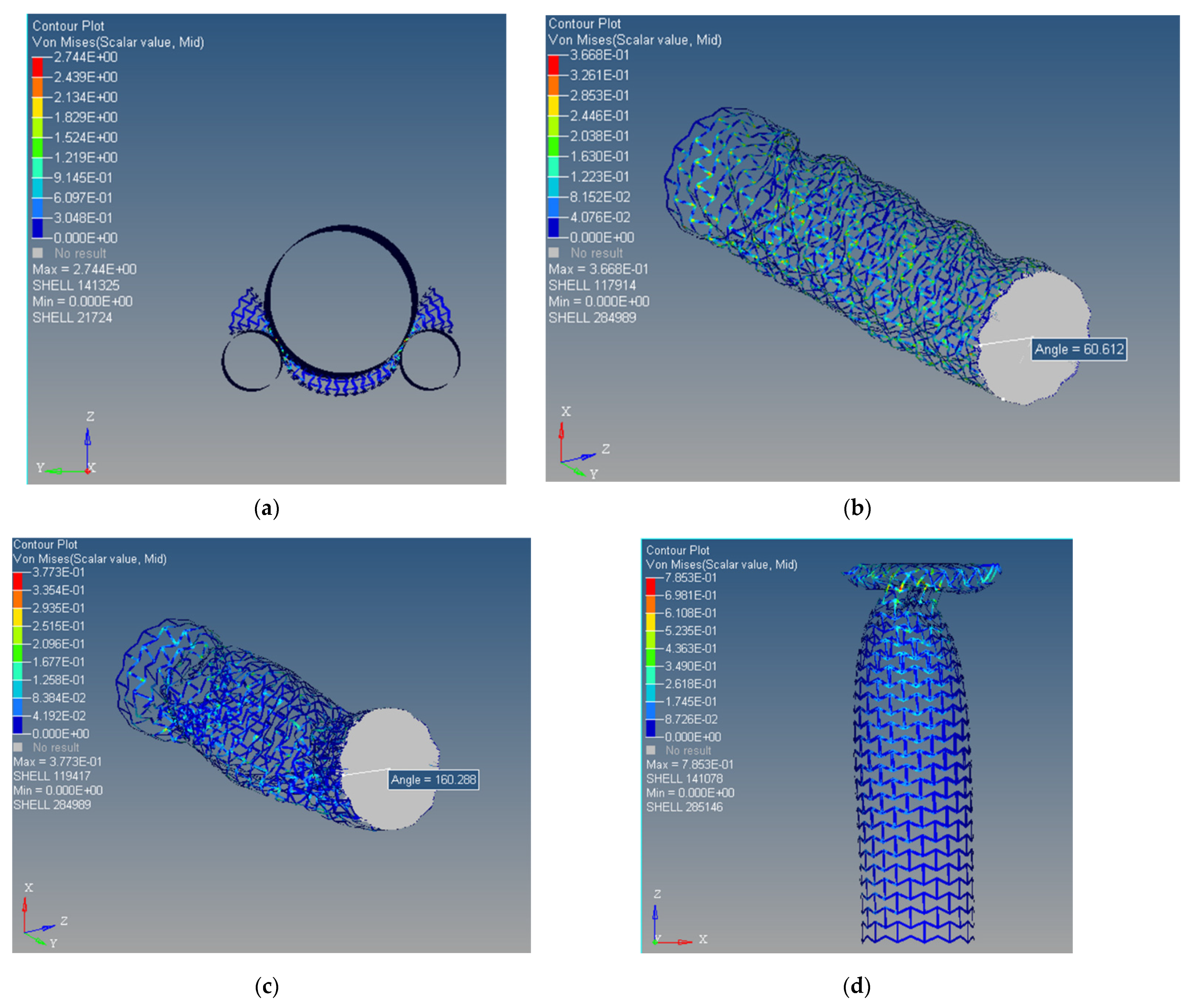
3.5. Finite Element Analysis

Von-Misses stress distributions of the deformed final state of the auxetic stent under three-point bending, 60° of twist, 160° of twist, and buckling, are shown in Figure 5a–d. Von-Misses stress distribution of auxetic stent under three-point bending given in Figure 5a shows the final stage where the loading pin almost touches to supporting pins. As the loading pin moved downward, Von-Misses stress intensified around the top part of the stent symmetrically right under the loading pin. Interestingly, there was almost no compressive stress region on the stent. The bottom side of the stent deformed, and the stent width expanded in the folded form. The deformed state predicted by FEA agrees perfectly with the direct mechanical three-point bending test results, the stent in the final stage expanded in width, and an inside opening was preserved even in the folded state.
Von-Misses stress distributions for 60° and 160° twisting, shown in Figure 5b,c respectively, show maximum Von-Misses stress value remained almost constant with a slight fluctuation around 350 MPa, which confirms that the auxetic stent undergoes plastic deformation at approximately 14° of the angles of twist and stress redistributed as the large deformations took place in the structure. Initially, the circular structure remained circular while the re-entrant cell structure opened and became rectangles around the edges of the stent. Then, the warping of the structure and local contractions were evident throughout the stent for 60° of rotation. These results match well with direct mechanical torsion test results where an enlargement takes place in-stent for a 160° angle of rotation. However, a local narrowing was not evident in the FEA torsion test, which may stem from the difference in boundary conditions: in the actual mechanical test, 3 mm at the edges was fixed while for simulations there were edge circles.
Von-Misses stress distributions of the auxetic stent in response to longitudinal compression in Figure 5d show that stress increased as the stent folded and reached the ultimate stress of the base material (785 MPa). Stress became concentrated around the buckling region as the stent deformed further. Buckling started after approximately 0.66 mm displacement as determined from direct mechanical tests and simulations also resulted in unstable deformation after 0.6 mm deflection of the upper plate. After 4 mm deflection, simulations predicted a failure where the stent loses unity of shape. A much narrower cross-section for the simulation was observed compared to the mechanical buckling test.

4. Discussion

The primary aim of this study was to show the potential of auxetic structure as a bare-metal stent. Mechanical evaluation of polymer/plastic auxetic stents is available in the literature [32,33,61,62]; however, the auxetic bare-metal stent produced by femtosecond micromachining has not been studied for in vitro mechanical and FEA simulations under mechanical loading. In this study, there was a good agreement observed between simulations and mechanical experiments under the different loading conditions.
In vitro mechanical testing for three-point bending significantly delayed loss of stent function because the passage of the stent never contracts, and the auxetic stent never develops sharp corners under bending, which may reduce concerns regarding artery damage. The stent did not break for a very prolonged deformation (Figure 6a), which stems from the re-entrant geometrical structure of the auxetic stent. Furthermore, the loading indenter interacts with its upper side, and it warps the loading indenter first while the bottom part of the stent starts bulging (Figure 6a). Due to nonlinear behavior, there was no stiffness value generated from the load-displacement curve. Thus, the auxetic stent becomes folded with a synclastic deformation and was never fully obstructed under three-point bending. For torsion, both torque and stress values in simulations show a steep increase, up to approximately 14°, no warping up to 45°, and this linear behavior, followed by a curve with much lower stiffness. Under torque-twist angle behavior, the auxetic stent also shows radial expansion, which presents an advantage of keeping the stent channel opened. There was a notable expansion in the cross-section in the auxetic stent, which is an indication of flexibility without yielding. For a high level of twisting angles up to 180, the auxetic stent brings an exceptional advantage by ensuring an opening preserved for the blood flow without obstruction (Figure 6b). Simulations match very well with the behavior of auxetic stents observed in direct mechanical tests for torsional loading. For longitudinal compression, the auxetic stent starts buckling under 0.6 mm displacement where buckling may occur either at the edges or around the middle of the stent, and the auxetic stent folds towards the inside, which can avoid artery damage. Simulations and direct mechanical results match well in predicting the point of buckling in the auxetic stent. It occurs almost at 5% compression, in the form of folding with a narrowed cross-section instead of in the form of bulging that can damage arteries (Figure 6c). Under lateral compression, the auxetic stent becomes almost completely folded towards the inside, and the diameter becomes smaller and avoids artery damage (Figure 6d). The auxetic stent can expand stably approximately 10% from its crimped form while showing longitudinal elongation. The current design of the stent can be a good alternative for arteries with a diameter around 5 mm, and it brings the advantage of keeping the blood vessel open with a stent implanted even for large deformations. The auxetic design brings the potentials of adjusting required stiffness by varying unit-cell dimensions without wrecking the deformation mechanism.
However, the auxetic stent produced for this study has laser welding points, and they are prone to fail under radial expansion. One of the specimens tested under balloon expansion showed more augmentation at one edge because of the failure of one of the welding points. Thus, laser welding points require specific attention because they may be prone to extreme pressure conditions. In this study, the fabricated auxetic stent specimens were only utilized for in vitro analysis under mechanical loadings, but not for in vivo animal models or clinically. Though the diameter of the fabricated auxetic stent is approximate, 5 mm (4.77 mm) is not fit for the coronary artery. Nonetheless, this auxetic stent design (re-entrant geometry) can be potentially extended for coronary artery stents.

5. Conclusions

Stents experience repetitive deformations due to the patient’s routine activities, which may lead to failure. The bare-metal auxetic stent design evaluated in our study for mechanical behavior may improve longitudinal contraction, radial strength, and stent migration, and therefore may be a good candidate for clinical applications. However, although there are various in vitro studies on auxetic stents described in the literature, in vivo animal studies or clinical experiments on the biocompatibilities of these stents have still not been performed yet. Therefore, further studies are needed to understand the benefits of auxetic stents.

Author Contributions

Conceptualization, S.K.B., H.L., M.B.G.J. and S.M.W.; methodology, S.K.B. and H.L.; software, S.K.B., H.L., A.A.K. and Y.C.; validation, S.K.B., H.L., M.B.G.J. and S.M.W. formal analysis, S.K.B., H.L., M.B.G.J. and S.M.W.; data curation, S.K.B., H.L., A.A.K. and Y.C.; writing—original draft preparation, S.K.B. and H.L.; writing—review and editing, S.K.B., H.L., M.B.G.J. and S.M.W.; project administration, S.K.B.; funding acquisition, S.K.B. All authors have read and agreed to the published version of the manuscript.

Funding

This work was supported by the Scientific and Technological Research Council of Turkey (TUBITAK), Grant No: 214 M377.

Institutional Review Board Statement

Not applicable.

Informed Consent Statement

Not applicable.

Data Availability Statement

Not applicable.

Acknowledgments

The research facility and support of the Bursa Technical University, Bursa, Turkey is greatly acknowledged. The fabrication of samples was performed at the laboratories of University of Victoria, BC, Canada. The authors also acknowledge the peer reviewers and editors for their helpful suggestions.

Conflicts of Interest

The authors declare no conflict of interest.

References

  1. Dobrin, P.B. Mechanical properties of arteries. Physiol. Rev. 1978, 58, 397–460. [Google Scholar] [CrossRef] [Green Version]
  2. Roy, C.S. The elastic properties of the arterial wall. J. Physiol. 2008, 3, 125–159. [Google Scholar] [CrossRef] [Green Version]
  3. Lee, A.Y.; Han, B.; Lamm, S.D.; Fierro, C.A.; Han, H.C. Effects of elastin degradation and surrounding matrix support on artery stability. Am. J. Physiol. Circ. Physiol. 2012, 302, H873–H884. [Google Scholar] [CrossRef] [Green Version]
  4. Liu, Q.; Han, H.C. Mechanical buckling of artery under pulsatile pressure. J. Biomech. 2012, 45, 1192–1198. [Google Scholar] [CrossRef] [Green Version]
  5. Chesnutt, J.K.W.; Han, H.C. Tortuosity triggers platelet activation and thrombus formation in microvessels. J. Biomech. Eng. 2011, 133, 121004. [Google Scholar] [CrossRef] [PubMed]
  6. Driver, M. Coatings for cardiovascular devices: Coronary stents. In Coatings for Biomedical Applications; Woodhead Publishing: Cambridge, UK, 2012; pp. 223–250. [Google Scholar]
  7. Duda, S.H.; Wiskirchen, J.; Tepe, G.; Bitzer, M.; Kaulich, T.W.; Stoeckel, D.; Claussen, C.D. Physical properties of endovascular stents: An experimental comparison. J. Vasc. Interv. Radiol. 2000, 11, 645–654. [Google Scholar] [CrossRef]
  8. Dyet, J.F.; Watts, W.G.; Ettles, D.F.; Nicholson, A.A. Mechanical properties of metallic stents: How do these properties influ-ence the choice of stent for specific lesions? Cardiovasc. Interv. Radiol. 2000, 23, 47–54. [Google Scholar] [CrossRef] [PubMed]
  9. Garg, S.; Serruys, P.W. Coronary stents: Current status. J. Am. Coll. Cardiol. 2010, 56, S1–S42. [Google Scholar] [CrossRef] [Green Version]
  10. Maleckis, K.; Deegan, P.; Poulson, W.; Sievers, C.; Desyatova, A.; MacTaggart, J.; Kamenskiy, A. Comparison of femoropopliteal artery stents under axial and radial compression, axial tension, bending, and torsion deformations. J. Mech. Behav. Biomed. Mater. 2017, 75, 160–168. [Google Scholar] [CrossRef] [PubMed]
  11. Borhani, S.; Hassanajili, S.; Tafti, S.H.A.; Rabbani, S. Cardiovascular stents: Overview, evolution, and next generation. Prog. Biomater. 2018, 7, 175–205. [Google Scholar] [CrossRef] [Green Version]
  12. Fischman, D.L.; Leon, M.B.; Baim, D.S.; Schatz, R.A.; Savage, M.P.; Penn, I.; Detre, K.; Veltri, L.; Ricci, D.; Nobuyoshi, M.; et al. A randomized comparison of coronary-stent placement and balloon angioplasty in the treatment of coronary artery disease. Stent Restenosis Study Investigators. N. Engl. J. Med. 1994, 331, 496–501. [Google Scholar] [CrossRef] [PubMed]
  13. Bennett, M.R.; O’Sullivan, M. Mechanisms of angioplasty and stent restenosis: Implications for design of rational therapy. Pharmacol. Ther. 2001, 91, 149–166. [Google Scholar] [CrossRef]
  14. Vos, N.S.; Fagel, N.D.; Amoroso, G.; Herrman, J.-P.R.; Patterson, M.S.; Piers, L.H.; van der Schaaf, R.J.; Slagboom, T.; Vink, M.A. Paclitaxel-coated balloon angioplasty versus drug-eluting stent in acute myocardial infarction: The REVELATION Ran-domized Trial. JACC Cardiovasc. Interv. 2019, 12, 1691–1699. [Google Scholar] [CrossRef] [PubMed]
  15. Bezrouk, A.; Hosszu, T.; Hromadko, L.; Olmrova, Z.; Kopecek, M.; Smutny, M.; Selke Krulichova, I.; Macak, J.M.; Kremlacek, J. Mechanical properties of a biodegradable self-expandable polydioxanone monofilament stent: In vitro force relaxation and its clinical relevance. PLoS ONE 2020, 15, e0235842. [Google Scholar] [CrossRef]
  16. Zilberman, M.; Eberhart, R.C. Drug-eluting bioresorbable stents for various applications. Annu. Rev. Biomed. Eng. 2006, 8, 153–180. [Google Scholar] [CrossRef] [Green Version]
  17. Charpentier, E.; Barna, A.; Guillevin, L.; Juliard, J.M. Fully bioresorbable drug-eluting coronary scaffolds: A review. Arch. Car-Diovasc. Dis. 2015, 108, 385–397. [Google Scholar] [CrossRef] [Green Version]
  18. Schmidt, W.; Behrens, P.; Brandt, W.C.; Siewert, S.; Grabow, N.; Schmitz, K.P. In vitro performance investigation of bioresorb-able scaffolds–standard tests for vascular stents and beyond. Cardiovasc. Revasc. Med. 2016, 17, 375–383. [Google Scholar] [CrossRef]
  19. Available online: https://med.stanford.edu/news/all-news/2019/11/invasive-heart-treatments.html (accessed on 15 March 2020).
  20. Canfield, J.; Totary-Jain, H. 40 years of percutaneous coronary intervention: History and future directions. J. Pers. Med. 2018, 8, 33. [Google Scholar] [CrossRef] [Green Version]
  21. Yelamanchili, V.S.; Hajouli, S. Coronary Artery Stents, StatPearls. 2020. Available online: https://0-www-ncbi-nlm-nih-gov.brum.beds.ac.uk/books/NBK559287/ (accessed on 15 March 2020).
  22. Chaparro-Rico, B.D.M.; Sebastiano, F.; Cafolla, D. A smart stent for monitoring eventual restenosis: Computational fluid dynamic and finite element analysis in descending thoracic aorta. Machines 2020, 8, 81. [Google Scholar] [CrossRef]
  23. Javaid, I.; Julian, G.; Patrick, W.S. Coronary stents: Historical development, current status and future directions. Br. Med. Bull. 2013, 106, 193–211. [Google Scholar] [CrossRef] [Green Version]
  24. Zhang, X.; Phil, J. Drug-Eluting Bioresorbable Stents, Med-Tech Innovation, The Communication Hub for the UK and Irish Medical Device Industry. Available online: http://www.med-techinnovation.com (accessed on 10 March 2020).
  25. Colombo, A.; Giannini, F.; Briguori, C. Should We Still Have Bare-metal stents available in our catheterization laboratory? J. Am. Coll. Cardiol. 2017, 70, 607–619, Erratum in J. Am. Coll. Cardiol. 2017, 70, 1541. [Google Scholar] [CrossRef]
  26. Meraj, P.M.; Jauhar, R.; Singh, A. Bare metal stents versus drug eluting stents: Where do we stand in 2015? Curr. Treat. Options Cardiovasc. Med. 2015, 17, 393. [Google Scholar] [CrossRef] [PubMed]
  27. Serruys, P.W.; van Hout, B.; Bonnier, H.; Legrand, V.; Garcia, E.; Macaya, C.; Sousa, E.; van der Giessen, W.; Colombo, A.; Sea-bra-Gomes, R.; et al. Randomised comparison of implantation of heparin-coated stents with balloon angioplasty in selected patients with coronary artery disease (Benestent II). Lancet 1998, 352, 673–681. [Google Scholar] [CrossRef]
  28. Biswas, S.; Duffy, S.J.; Lefkovits, J.; Andrianopoulos, N.; Brennan, A.; Walton, A.; Chan, W.; Noaman, S.; Shaw, J.A.; Dawson, L.; et al. Australian trends in procedural characteristics and outcomes in patients undergoing percutaneous coronary intervention for ST-elevation myocardial infarction. Am. J. Cardiol. 2018, 121, 279–288. [Google Scholar] [CrossRef]
  29. Rymer, J.A.; Harrison, R.W.; Dai, D.; Roe, M.T.; Messenger, J.C.; Anderson, H.V.; Peterson, E.D.; Wang, T.Y. Trends in bare-metal stent use in the United States in patients aged ≥65 years (from the CathPCI Registry). Am. J. Cardiol. 2016, 118, 959–966. [Google Scholar] [CrossRef] [PubMed]
  30. Choubey, R.K.; Pradhan, S.K. Prediction of strength and radial recoil of various stents using FE analysis. Mater. Today Proc. 2020, 27, 2254–2259. [Google Scholar] [CrossRef]
  31. Cockerill, I.; See, C.W.; Young, M.L.; Wang, Y.; Zhu, D. Designing better cardiovascular stent materials: A learning curve. Adv. Funct. Mater. 2021, 31, 2005361. [Google Scholar] [CrossRef] [PubMed]
  32. Hoffmann, R.; Mintz, G.S.; Dussaillant, G.R.; Popma, J.J.; Pichard, A.D.; Satler, L.F.; Kent, K.M.; Griffin, J.; Leon, M.B. Patterns and mechanisms of in-stent restenosis. A serial intravascular ultrasound study. Circulation 1996, 94, 1247–1254. [Google Scholar] [CrossRef]
  33. Kastrati, A.; Mehilli, J.; Dirschinger, J.; Pache, J.; Ulm, K.; Schühlen, H.; Seyfarth, M.; Schmitt, C.; Blasini, R.; Neumann, F.J.; et al. Restenosis after coronary placement of various stent types. Am. J. Cardiol. 2001, 87, 34–39. [Google Scholar] [CrossRef]
  34. Nuhn, H.; Blanco, C.E.; Desai, T.A. Nanoengineered stent surface to reduce in-stent restenosis in vivo. ACS Appl. Mater. Interfaces 2017, 9, 19677–19686. [Google Scholar] [CrossRef]
  35. Guildford, A.; Santin, M.; Phillips, G.J. Cardiovascular stents. In Biomaterials and Devices for the Circulatory System; Woodhead Publishing: Cambridge, UK, 2010; pp. 173–216. [Google Scholar]
  36. Udriște, A.S.; Niculescu, A.-G.; Grumezescu, A.M.; Badila, E. Cardiovascular stents: A review of past, current, and emerging devices. Materials 2021, 14, 2498. [Google Scholar] [CrossRef] [PubMed]
  37. Bhullar, S.K. Influence of Negative Poisson′s Ratio on Stent Applications. Adv. Mater. 2013, 2, 42. [Google Scholar] [CrossRef]
  38. Ren, X.; Shen, J.; Ghaedizadeh, A.; Tian, H.; Xie, Y.M. A simple auxetic tubular structure with tuneable mechanical properties. Smart Mater. Struct. 2016, 25, 65012. [Google Scholar] [CrossRef]
  39. Liu, R.; Xu, S.; Luo, X.; Liu, Z. Theoretical and numerical analysis of mechanical behaviors of a metamaterial-based shape memory polymer stent. Polymers 2020, 12, 1784. [Google Scholar] [CrossRef] [PubMed]
  40. Wu, W.; Song, X.; Liang, J.; Xia, R.; Qian, G.; Fang, D. Mechanical properties of anti-tetrachiral auxetic stents. Compos. Struct. 2018, 185, 381–392. [Google Scholar] [CrossRef]
  41. Ruan, X.L.; Wu, W.W.; Song, X.K.; Li, J.J.; Xia, R. Design and characterization of the 3D antichiral-reentrant hybrid structure for intravascular stent. Int. J. Appl. Mech. 2018, 10, 1850105. [Google Scholar] [CrossRef]
  42. Ning, X.; Yu, X.; Wang, H.; Sun, R.; Corman, R.E.; Li, H.; Lee, C.M.; Xue, Y.; Chempakasseril, A.; Yao, Y. Mechanically active materials in three-dimensional mesostructures. Sci. Adv. 2018, 4, eaat8313. [Google Scholar] [CrossRef] [Green Version]
  43. Wojciechowski, K.W. Two-dimensional isotropic system with a negative Poisson ratio. Phys. Lett. A 1989, 137, 60–64. [Google Scholar] [CrossRef]
  44. Wu, W.; Qi, M.; Liu, X.P.; Yang, D.Z.; Wang, W.Q. Delivery and release of nitinol stent in carotid artery and their interactions: A finite element analysis. J. Biomech. 2007, 40, 3034–3040. [Google Scholar] [CrossRef]
  45. Timmins, L.H.; Miller, M.W.; Clubb, F.J., Jr.; Moore, J.E., Jr. Increased artery wall stress post-stenting leads to greater intimal thickening. Lab. Investig. 2011, 91, 955–967. [Google Scholar] [CrossRef] [Green Version]
  46. Dumoulin, C.; Cochelin, B. Mechanical behaviour modelling of balloon-expandable stents. J. Biomech. 2000, 33, 1461–1470. [Google Scholar] [CrossRef]
  47. Lakes, R.S. Advances in negative Poisson’s ratio materials. Adv. Mater. 1993, 5, 293–296. [Google Scholar] [CrossRef]
  48. Evans, K.E.; Alderson, A. Auxetic materials: Functional materials and structures from lateral thinking! Adv. Mater. 2000, 12, 617–628. [Google Scholar] [CrossRef]
  49. Lakes, R.S. Negative Poisson’s ratio materials. Science 1987, 238, 551. [Google Scholar] [CrossRef] [PubMed]
  50. Yang, W.; Li, Z.M.; Shi, W.; Xie, B.H.; Yang, M.B. Review on auxetic materials. J. Mater. Sci. 2004, 39, 3269–3279. [Google Scholar] [CrossRef]
  51. Lekesiz, H.; Bhullar, S.K.; Karaca, A.A.; Jun, M.B.G. Mechanical characterization of auxetic stainless steel thin sheets with reentrant structure. Smart Mater. Struct. 2017, 26, 085022. [Google Scholar] [CrossRef]
  52. Gatt, R.; Caruana-Gauci, R.; Attard, D.; Casha, A.R.; Wolak, W.; Dudek, K.; Mizzi, L.; Grima, J.N. On the properties of real fi-nite-sized planar and tubular stent-like auxetic structures. Phys. Status Solidi Basic Res. 2014, 251, 321–327. [Google Scholar] [CrossRef]
  53. Mizzi, L.; Attard, D.; Casha, A.; Grima, J.N.; Gatt, R. On the suitability of hexagonal honeycombs as stent geometries. Phys. Status Solidi Basic Res. 2014, 251, 328–337. [Google Scholar] [CrossRef]
  54. Amin, F.; Ali, M.N.; Ansari, U.; Mir, M.; Minhas, M.A.; Shahid, W. Auxetic coronary stent endoprosthesis: Fabrication and structural analysis. J. Appl. Biomater. Funct. Mater. 2015, 13, E127–E135. [Google Scholar] [CrossRef]
  55. Geng, L.C.; Ruan, X.L.; Wu, W.W.; Xia, R.; Fang, D.N. Mechanical properties of selective laser sintering (SLS) additive manu-factured chiral auxetic cylindrical stent. Exp. Mech. 2019, 59, 913–925. [Google Scholar] [CrossRef]
  56. Bhullar, S.K.; Ko, J.; Cho, Y.; Jun, M.B.G. Fabrication and characterization of nonwoven auxetic polymer stent. Polym.-Plast. Technol. Eng. 2015, 54, 1553–1559. [Google Scholar] [CrossRef]
  57. Wu, W.; Hu, W.; Qian, G.; Liao, H.; Xu, X.; Berto, F. Mechanical design and multifunctional applications of chiral mechanical metamaterials: A review. Mater. Des. 2019, 180, 107950. [Google Scholar] [CrossRef]
  58. Xue, H.; Luo, Z. Design of auxetic coronary stents by topology optimization. In Computational Biomechanics for Medicine; Springer: Cham, Switzerland, 2019; pp. 17–31. [Google Scholar]
  59. Prithipaul, P.K.M.; Kokkolaras, M.; Pasini, D. Assessment of structural and hemodynamic performance of vascular stents modelled as periodic lattices. Med. Eng. Phys. 2018, 57, 11–18. [Google Scholar] [CrossRef] [PubMed] [Green Version]
  60. Liulan, L.; Qingxi, H.; Xianxu, H.; Gaochun, X. Design and fabrication of bone tissue engineering scaffolds via rapid prototyping and CAD. J. Rare Earths 2007, 25, 379–383. [Google Scholar] [CrossRef]
  61. Snowhill, P.B.; Nosher, J.L.; Siegel, R.L.; Silver, F.H. Characterization of radial forces in Z stents. Investig. Radiol. 2001, 36, 521–530. [Google Scholar] [CrossRef] [PubMed]
  62. Sullivan, T.M.; Ainsworth, S.D.; Langan, E.M.; Taylor, S.; Snyder, B.; Cull, D.; Youkey, J.; Laberge, M. Effect of endovascular stent strut geometry on vascular injury, myointimal hyperplasia, and restenosis. J. Vasc. Surg. 2002, 36, 143–149. [Google Scholar] [CrossRef]
  63. De Bock, S.; Iannaccone, F.; De Beule, M.; Van Loo, D.; Vermassen, F.; Verhegghe, B.; Segers, P. Filling the void: A coalescent numerical and experimental technique to determine aortic stent graft mechanics. J. Biomech. 2013, 46, 2477–2482. [Google Scholar] [CrossRef]
  64. Prendergast, P.J.; Lally, C.; Daly, S.; Reid, A.J.; Lee, T.C.; Quinn, D.; Dolan, F. Analysis of prolapse in cardiovascular stents: A constitutive equation for vascular tissue and finite-element modelling. J. Biomech. Eng. 2003, 125, 692–699. [Google Scholar] [CrossRef]
  65. Jedwab, M.R.; Clerc, C.O. A study of the geometrical and mechanical properties of a self-expanding metallic stent-theory and experiment. J. Appl. Biomater. 1993, 4, 77–85. [Google Scholar] [CrossRef]
  66. Kalmar, G.; Hubner, F.; Voelker, W.; Hutzenlaub, J.; Teubner, J.; Poerner, T.; Suselbeck, T.; Borggrefe, M.; Haase, K.K. Radial force and wall apposition of balloon-expandable vascular stents in eccentric stenosis: An in vitro evaluation in a curved vessel model. J. Vasc. Interv. Radiol. 2002, 13, 499–508. [Google Scholar] [CrossRef]
  67. Fortier, A.; Gullapalli, V.; Mirshams, R.A. Review of biomechanical studies of arteries and their effect on stent performance. IJC Heart Vessel. 2014, 4, 12–18. [Google Scholar] [CrossRef] [Green Version]
Figure 1. Challenges with mechanical properties of stents: longitudinal compression, bending, radial compression and torsion.
Applsci 12 00910 g001
Figure 2. (a) Unit-cell structure for re-entrant geometry; (b) repeating unit-cell pattern femtosecond micromachined laser-cut stainless-steel metal plate; and (c) fabricated laser-welded auxetic stent.
Applsci 12 00910 g002
Figure 3. Mechanical testing set-up to perform (a) three-point bending; (b) longitudinal compression; (c) lateral compression; (d) torsion and (e) radial expansion.
Applsci 12 00910 g003
Figure 4. Mechanical test results: (a) displacement vs. force under three-point bending; (b) angle of twist vs. torque under torsion; (c) pressure vs. diameter under radial expansion; (d) pressure vs. length under radial expansion; (e) displacement vs. force under longitudinal compression; and (f) displacement vs. force under lateral compression.
Applsci 12 00910 g004
Figure 5. Von-Misses stress distributions for stents at failure stage based on finite element analysis: (a) three-point bending; (b) 60° angle of twist; (c) 160° angle of twist; and (d) longitudinal compression.
Applsci 12 00910 g005
Figure 6. Failed stent samples under: (a) three-point bending; (b) torsion; (c) longitudinal compression; and (d) lateral compression.
Applsci 12 00910 g006
Publisher’s Note: MDPI stays neutral with regard to jurisdictional claims in published maps and institutional affiliations.

