
Quantitative Evaluation of Light Collimating for Commercial UV-LEDs Based on Analytic Collimating Lens


Department of Mechanical Engineering, Cheng Kung University, Tainan 701, Taiwan
*
Author to whom correspondence should be addressed.
Appl. Sci. 2022, 12(2), 911; https://0-doi-org.brum.beds.ac.uk/10.3390/app12020911
Submission received: 21 December 2021
/
Revised: 11 January 2022
/
Accepted: 13 January 2022
/
Published: 17 January 2022
(This article belongs to the Special Issue Optical Design and Engineering II)
Abstract
:This paper proposes a lens design method for effectively collimating the light emitting from a light-emitting diode (LED). This collimating lens contains two aspherical lens surfaces which can be mathematically characterized using a few designing parameters, and hence is called an analytic collimating lens. An optical ray-tracing algorithm has been developed for these analytic collimating lenses to analyze their optical performance and to optimize their designs. Six high-power and commercially available ultraviolet (UV) LEDs are chosen as examples for demonstrating the optimal collimating lens design. For each UV-LED, the corresponding optical collimating lens is determined by inputting the ray data file provided by the manufacture over a finite-size emitting area. The divergent angles of the six UV-LEDs have been successfully collimated to a narrow range in between 1.56° to 2.84° from their original radiation angle around 46° to 120°. Furthermore, the proposed analytical collimating lenses are suitable for mass-production using standard mold injection methods, and hence possess great potentials for industry applications of LEDs.
1. Introduction
Ultraviolet light-emitting diodes (UV-LEDs) have developed rapidly in the past few years with great potentials for many engineering applications. One example is in photolithography for replacing traditional mercury lamps with UV-LEDs with the advantages of lower cost, faster on-off switching time, lower power consumption, longer lifetime, higher stability, and environment-friendliness. As the power of a single UV-LED is still very limited so far, one strategy is to deploy an array of UV-LEDs to form a planar UV light source and then combine with scanning movement to achieve uniform exposure of UV dose over a larger planar area for contact/proximity photolithography [1]. In this case, it is necessary to collimate the UV light emitted from UV-LEDs, which under the premise of not losing too much light energy, is still a challenging issue.
The collimation of UV-LEDs usually requires special lens designs, such as primary or secondary optical designs to redistribute the ray. The lens design of secondary optics has been widely used to refract or reflect UV-LED. For example, refractive lenses with a concave curved surface on one side and a freeform surface on the other side had been designed [2,3,4] to achieve a uniform luminous intensity on a rectangular luminous area. According to different radiation angles of extended light sources, collimating lenses were designed [5,6,7,8,9,10,11,12,13] with reflection on one side and a refraction type on the other side using simultaneous multiple surface method (SMS). Thøger Kari [14] observed that the total internal reflection (TIR) structure can be employed to construct the purpose of collimating the LED light with compact volume under the point source approximations, but collimation and optical efficiency were still having a scope for improvement. Therefore, the use of point source approximations in compact lens designs is discouraged. For UV-LEDs with inherently larger radiation divergence angles, complex freeform surfaces are usually needed to refract light ray to enhance collimation. Positive meniscus lenses composed of two spherical surfaces were also proposed [15,16] for LED’s light collimating, but the collimation ability is limited near the optical axis and hence the efficiency is low.
There are many methods to manufacture axisymmetric aspherical lenses, Eric Logean [17] using wafer-level etching to fabricate high numerical aperture silicon collimating lens in parallel. R.R.A. Syms [18] made use of surface tension self-assembly to construct refractive collimating microlens arrays. Another more important approach to produce optical lenses is glass molding technology [19], Yue Zhang improved quality of lenses according to performance evaluation of experiments and analysis. For the application of UV-LEDs in photolithography, collimation of UV light is critical for it directly affects the dimensional accuracy of developed photoresist microstructures and the verticality of structural sidewalls [20,21]. Another important application of UV-LEDs is for the imaging homogenization system [22,23], in which fly’s eye homogenizers are typically used. Such an imaging homogenization system requires high collimation of incident light [24] to reduce optical crosstalk on the detector plane and improve energy efficiency.
At present, most of the research works related to lens design investigate the problem of optical illumination instead of optical collimation. However, if we consider a light source of the finite luminous area with divergence angle in the case of optical collimation, the collimating ability of the lens is restricted. Therefore, this research extends the previously proposed analytic collimating lens [25] based on the hypothesis of a point source with an infinite light-emitting area, and then explores an extended UV-LED light source with a finite light-emitting area. Refer to Appendix A for the design principle and derivation process of the analytic collimating lens.
2. Design of Analytic Collimating Lens for Light Collimation
2.1. Commercial UV-LED Light Source and Lens Material
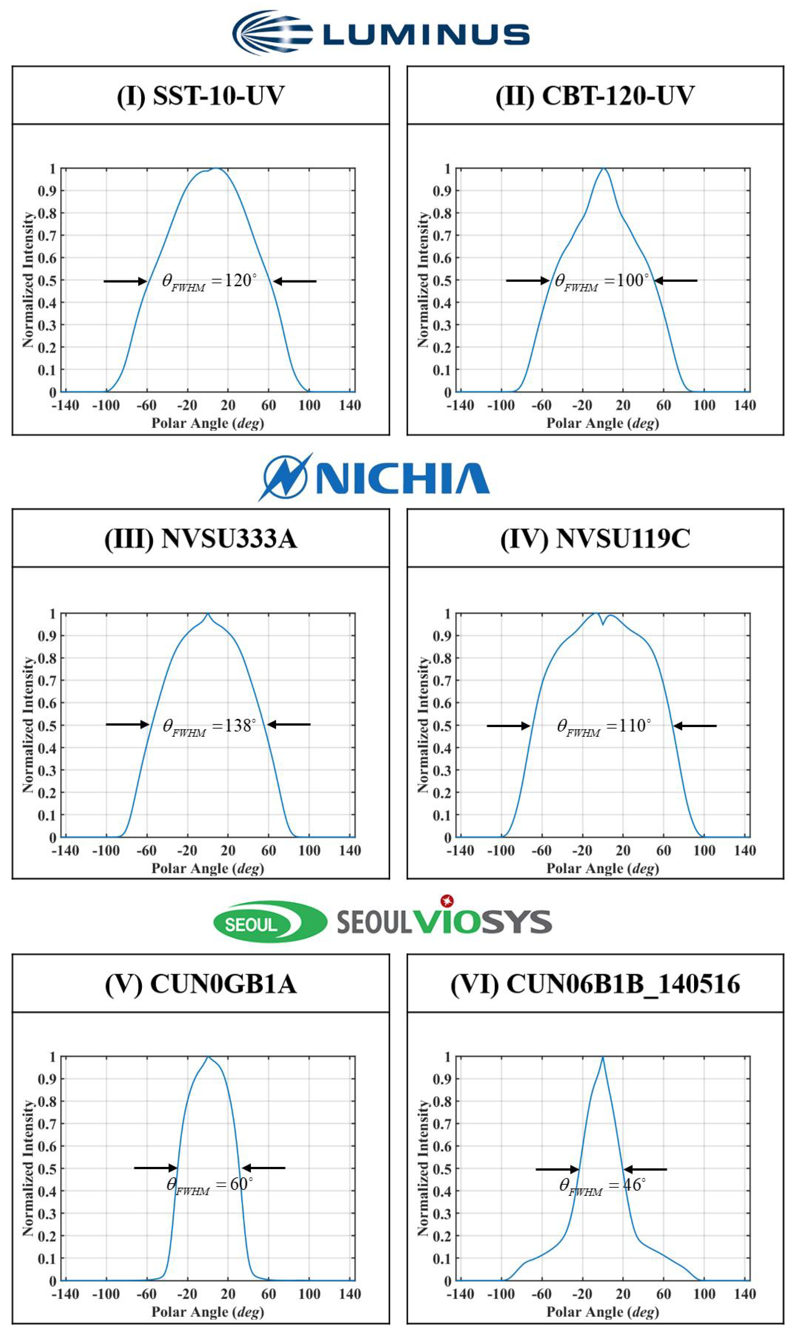
The goal of this work is for light collimation of UV-LEDs for lithography applications. Therefore, six high-power commercial UV-LEDs with a peak wavelength of 405 nm are chosen from three major UV-LED suppliers, namely, Luminus, Inc. (Sunnyvale, CA 94086, USA), NICHIA Co. (Anan-Shi, Tokushima 774-8601, Japan) and Seoul Viosys (Ansan-si, Gyeonggi-do, Korea). The main specifications of the six chosen UV-LEDs labeled from (I) to (VI) are listed in Table 1. The light-emitting area sizes of the chosen UV-LEDs are from 1 × 1 mm2 to 4.63 × 2.6 mm2, and the output optical powers range from 1.16 W to 19.5 W. The radiation patterns, or the angular distribution of emitted optical power intensity, of the six UV-LEDs are available and have been extracted from companies’ websites. The optical simulation software Zemax OpticStudio (Kirkland, WA, USA) was used to export the radiation pattern of each commercial UV-LED from their corresponding ray data files. Figure 1 shows the obtained radiation patterns of each of the six UV-LEDs used in this work. We will use the angle of full width at half maximum of radiation pattern as the indication of directivity of the UV-LEDs, which covers from 46° to 120° for the six chosen UV-LEDs as shown in Table 1 and Figure 1.
For the sake of mass production, the lens material is selected as PLEXIGLAS®8012 (Evonik Performance Materials GmbH, Essen, Germany) which is a type of polymethylmethacrylate (PMMA) polymer material commonly used in plastic injection molding. This UV-graded PMMA lens material has excellent transmittance and an optical refractive index of 1.51 at the wavelength of 405 nm [26]. The availability of using this PMMA material for injection molding allows mass production of the collimating lenses at high throughput and low cost.
2.2. Analytic Collimating Lens Design
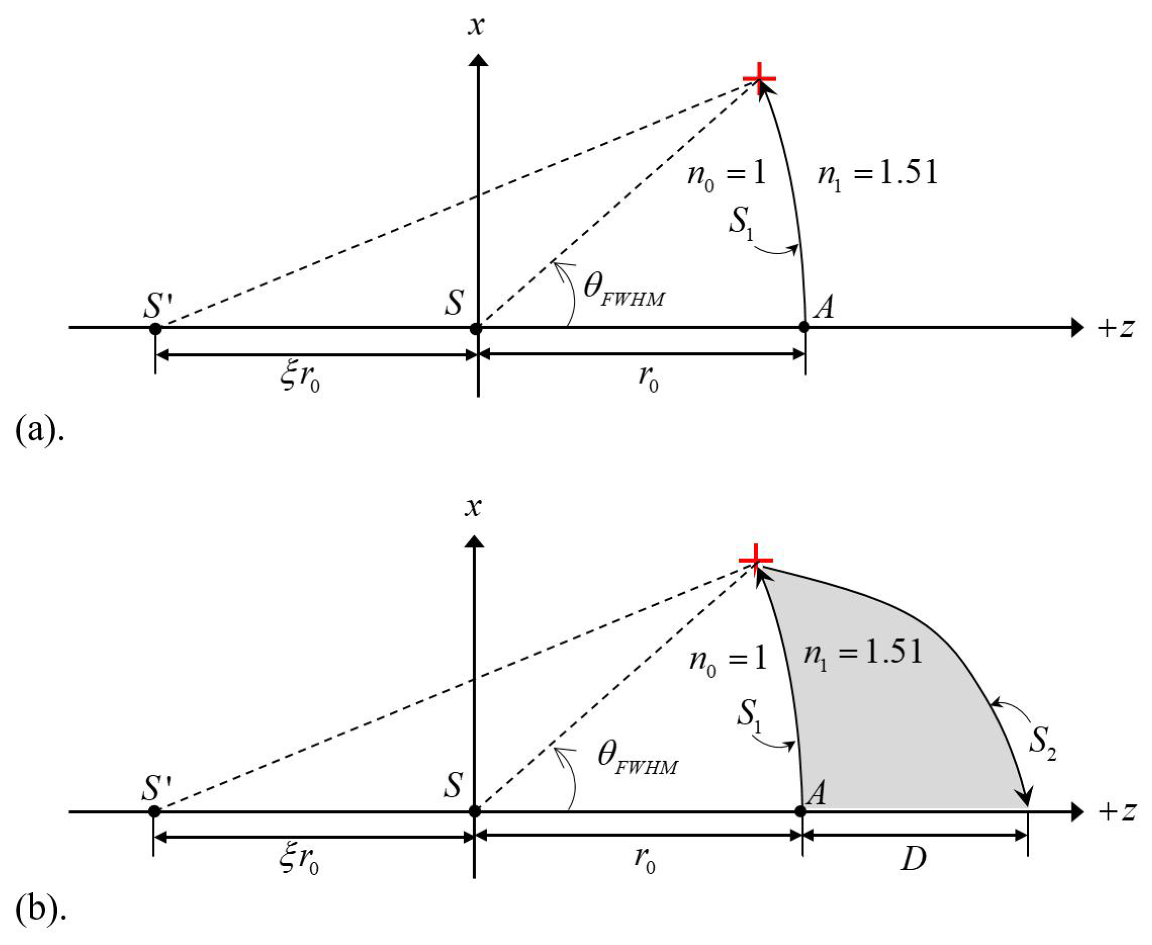
The theory of designing an analytic collimating lens was proposed earlier [25] and is schematically depicted in Figure 2, in which the axis represents the principle optical axis of the LED light source with its center located at point S. As shown in Figure 2, the analytic-collimating lens contains two analog and non-spherical lens surfaces, and , which are both axially symmetrical with respect the optical axis of axis. The on axis distance between the centers of the first lens surface and the LED light source is denoted as . The working principle of this analytic collimating lens is to refract all light rays emitting from S by the lens surface at the air/lens interface such that the transmitted rays in the lens material can be viewed as all radiating from a virtual light source located at . The distance between S and is , in which the is a non-dimensional parameter one can determine in designing the analytic collimating lens. Finally, the lens surface is designed to refract all the light rays again at the lens/air interfaced in such a way after refraction and all light rays in the air are parallel to the optical axis. Both the surface profiles of and can be analytically or mathematically derived with given information on , and optical refraction index of the lens material (). Details are given in the Appendix A and [25]. The goal of this research is to optimize the design of the analytic collimating lenses for each of the six chosen UV-LEDs by adjusting the two parameters of and to achieve a much-collimated UV light beam with smaller divergent angle and larger energy efficiency.
Another parameter that needs to be chosen for finalizing the lens design is the full aperture angle of the lens. As shown in Figure 1, we will assign the directivity angle () of each UV-LED to be the full aperture lens angle in designing its corresponding collimating lens. By doing so we can make each lens collect approximately the same percentage of total LED’s power, which forms the basis for fair comparison of the designed collimating lenses. As shown in Figure 2b, both lens surfaces ( and ) can be analytically decided based on chosen parameters of and , and D is the central thickness of this collimating lens which unit is mm.
2.3. Analysis of Collimated Light
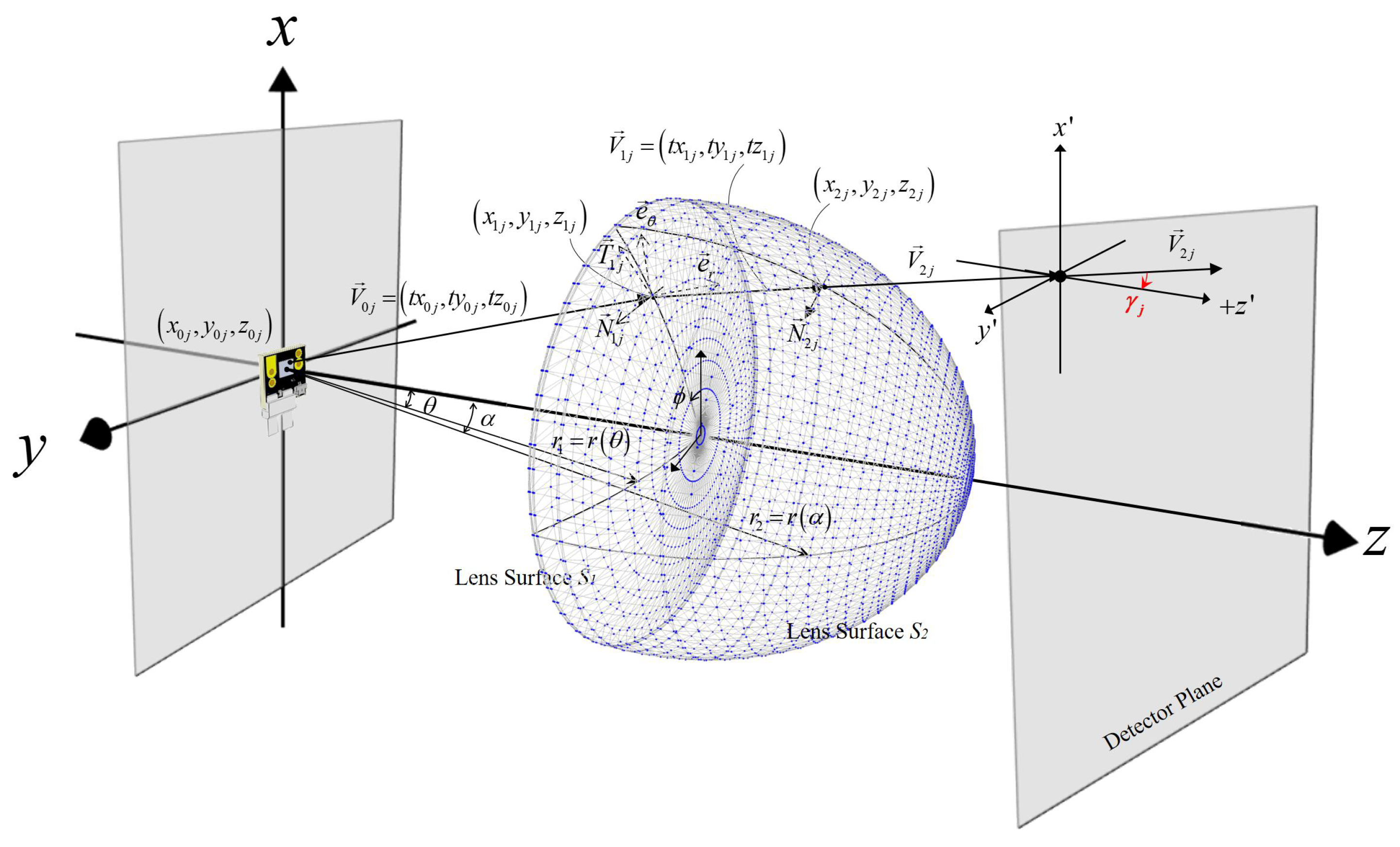
As the collimating lens is axially symmetrical, the two lens profiles shown in Figure 2 can rotate 360° around the optical axis ( axis) to form two lens surfaces indicated as and in Figure 3. In Figure 3, the illuminating surface area of the UV-LED under evaluation located at the original plane and a detector plane that collects all the UV light after collimating are shown. A ray-tracing algorithm has been developed in this work to carry out the evaluation. Generally speaking, the ray data file for each UV-LED light source contains millions of optical rays emitting from the LED luminance area. Each ray has 7 variables which will be indicated as to describe the jth ray originated from the LED chip. represents the coordinates of the starting point of the ray, represents the directional cosines of the ray with respect to the coordinate system, and represents the optical power () carried by the jth ray from the UV-LED chip.
Referring to Appendix A and Figure A1, the surfaces and of the analytic collimating lens are mathematically characterized by functions and , respectively. Since the property of axially symmetrical, the lens’s surfaces and can then be characterized by rotating and 360° with respect to the z axis, as shown in Figure 3. The ray emitted from travels along the direction with intersects the lens surface at the point . Let represent the directional vector of the jth ray after being refracted by the ith surface and represent the coordinates of interception point of the jth ray with the ith surface, in which i equals 1 or 2 for lens surfaces and , respectively.
As both lens surfaces had been analytically characterized, all the and can be numerical solved using parameter root-finding algorithm such as Newton-Raphson method. Furthermore, considering the vector analysis of the spherical coordinate system and the axisymmetric curve, the unit normal vectors and of the jth incident ray intercepting surfaces and , respectively, can be determined by,
in which, and are the functions for characterizing surfaces and , respectively. In the two-dimensional polar coordinate system shown in Appendix A and Figure A1, and are first derivatives with respect to their variables. The azimuth angle is referring to the angle between the axis and the projection of the position vector of each interception point at the plane.
Based on the vector form of Snell’s law, one can readily derive,
where and are the optical refraction indices of air and the lens material, respectively. Once the are calculated, the angle between the refracted jth ray and the -axis can be determined as Equation (9). is the angle between the refractive vector and optical axis.
As each incident ray has been refracted twice by the two lens surfaces, the optical energy carried by each ray suffers two Fresnel’s losses which can be readily calculated based on a standard formula and all data obtained earlier. Therefore, the remaining optical energy of the jth ray reaching the detector plane is calculated and denoted as . Considering the optical power as a weighting factor, we can define a weighted mean value of the divergent angles of all the refracted rays as Equation (10).
where M is the total number of rays involved in the calculation. The represents the weighted mean divergence angle of the collimated LED light and therefore serves as an index for quantitative evaluation of the collimating effect. The lens design is aiming at achieving the smallest by adjusting all the lens design parameters.
3. Numerical Calculation
3.1. Data Analysis
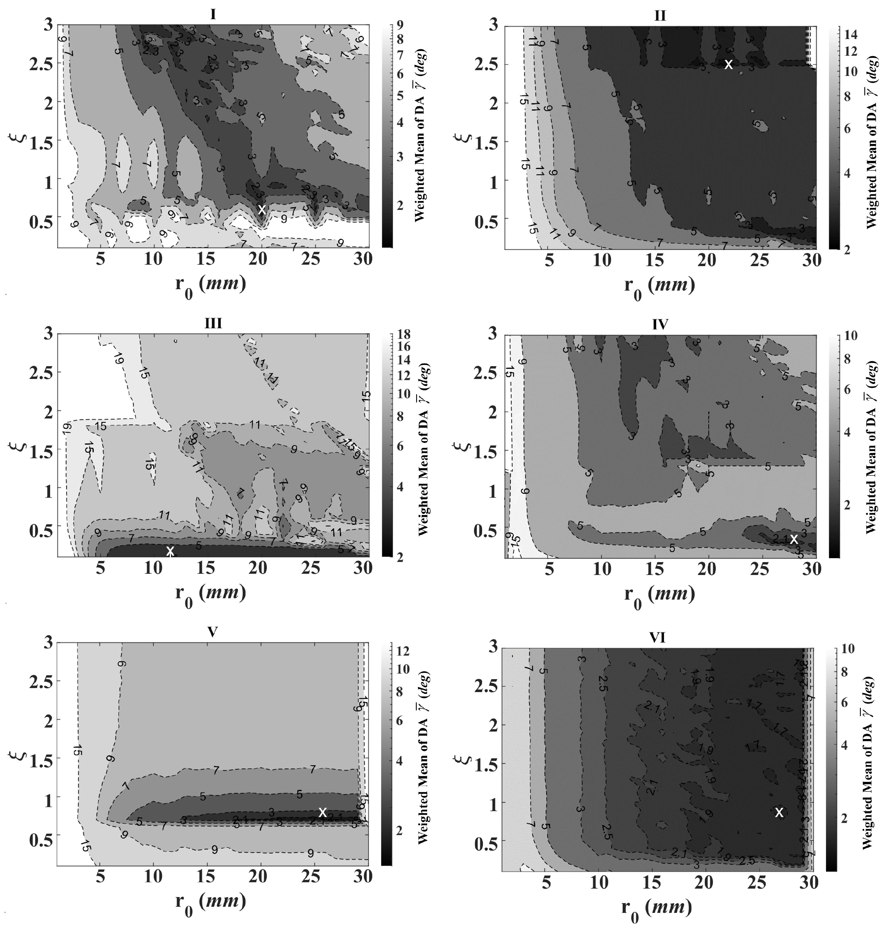
In the previous section, an analytical collimating lens can be designed for a UV-LED based on two parameters, and , and a ray-tracing program is developed for analyzing the divergent angles and remaining powers of all the LED’s rays being collected and collimated by the designed lens. The light collimating performance as well as the power efficiency of the designed lens for a given LED light source can be quantitatively evaluated in a prompt and efficient manner. For each of the six chosen commercial UV-LEDs, typically 1 million rays have been used in the numerical simulation for searching for the best lens design with the optimal optical performance. Based on the practical considerations, the range of the variables are set to be 1 mm ≤ ≤ 30 mm and , such that the designed lenses are with reasonable sizes and optical power intensity for lens manufacturing and applications. The numerical simulation is carried out with a searching step size of 1 mm for and 0.1 for . Therefore, for each of the six commercial UV-LED light sources, a dual-variable local search model with a total of 900 groups is built. The analytic lens design with the best light collimation ability and optical efficiency is established by determining the values of and .
Figure 4 shows the contours of the divergence angle of the six commercial UV-LED light sources after analytic lens surface design and optical ray tracing. The x-axis and y-axis represent and , respectively. The grayscale value of the color bar represents the weighted mean of divergence angle for each combination of and . With an increasing value of , the light collimation ability in this contour map shows a trend of improvement. It indicates that when the UV-LED light-emitting area is relatively much smaller than the lens aperture size, better collimation ability can be achieved since the LED light source is closer to a point source to the lens.
3.2. Optimized Parameters after Evaluation
Based on the numerically calculated data as shown in Figure 4, the optimized parameters of and with the smallest weighted mean divergence angle are selected for each of the six UV-LEDs and are shown in the 3rd and the 4th columns of Table 2. Moreover, the corresponding optical efficiency (OE) is evaluated by considering the numerical aperture of the first aspheric lens that could collect light rays from certain LEDs and Fresnel’s loss of twice refraction. It is listed in the last column of Table 2. Additionally, a dimensionless physical quantity, the dimensional factor (DF) , is defined as the ratio of the UV-LED light-emitting area size to the parameter and is listed in the 5th column of Table 2. The dimensional factor is used to characterize the relative dimension size of the LED’s light-emitting area in comparison with the aperture size of the collimating lens. The commonly accepted idea is that light collimating of LEDs can be much more easily achieved with a small value of dimensional factor .
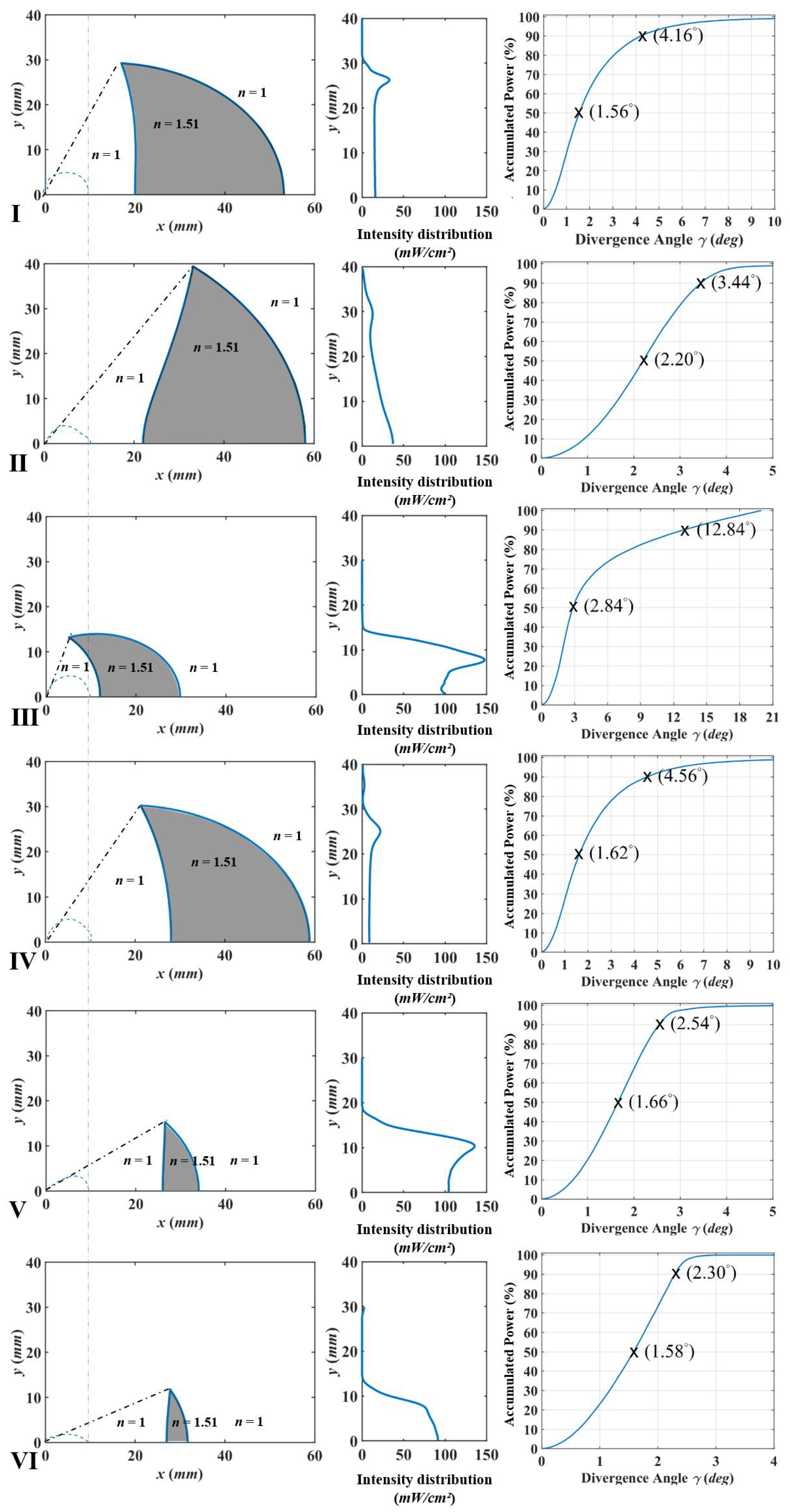
Based on the chosen values of and shown in Table 2, the collimating lenses for the six UV-LEDs are now decided and their lens surface profiles are plotted and displayed at the left-hand side in Figure 5, in which the shaded area being the lens material of PMMA. The radiation patterns of the corresponding UV-LEDs are also shown in dash lines along with the designed collimating lenses’ profiles in Figure 5. As being mentioned before, the aperture angle of each collimating lens is designed to match the directivity angle with a level of 50% normalized intensity in the radiation pattern of each UV-LED.
To evaluate the over performance of the designed collimating lens for each UV-LED in detail, the designed lens’ surface profiles are built into a CAD file by SolidWorks (Dassault Systèmes SE, Vélizy-Villacoublay, France) and is input along with the corresponding LED’s ray data file to the optical simulation software Zemax OpticStudio (Kirkland, WA, USA) for light collimation and optical efficiency verification. In the simulation by Zemax software, the detector plane is placed at mm away from the LED light source. Distributions of incoherent irradiance on the detector plane for each UV-LED with its corresponding collimating lens are shown in the central column in Figure 5. It is shown that the optical intensity distribution after collimating can vary significantly. Finally, the statistics on accumulated total optical energy as a function of divergent angle are also extracted from the data simulated by Zemax software and are displayed on the right-hand side in Figure 5. and are the divergence angles (DA) which can cover 50% and 90% of the totally accumulative intensity of the light after collimation. The obtained values of and for the six UV-LEDs with their corresponding lenses are listed in the 6th and the 7th columns in Table 2.
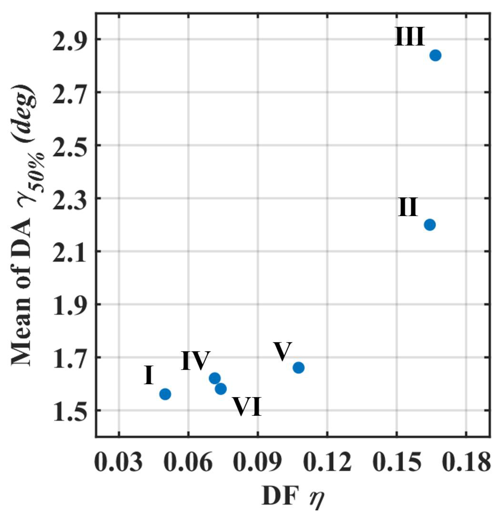
Taking UV-LED (I) as an example, Table 2 shows that 50% of the light energy has a divergence angle within 1.56°, and 90% of the light energy has a divergence angle within 4.16°. With the analytic collimating lens design, the divergence angle is reduced from 120° to 1.56°. Compared with the other five UV-LEDs, the UV-LED (I) has better light collimation partially due to a relatively smaller dimension factor of 0.05. On the contrary, the UV-LED (III) has a relatively large dimensional factor which results in the worst collimation ability. The relationship between the divergence angle which is 50% of the totally accumulative intensity of the light after collimation and the dimensional factor for the six commercial UV-LEDs is shown in Figure 6. The explanation of the dimensional factor is LED-to-lens size ratios. In other words, the case of a smaller dimensional factor is close to ideal point source approximations. Therefore, the divergence angle after collimation is smaller. As an indication of the ratio of the light-emitting area to the lens aperture, the dimensional factor can predict the divergence angle after collimation because and are positively correlated.
4. Conclusions
In this paper, we propose a lens design method and a quantitative evaluation method for light collimating of commercial UV-LEDs. Six high-power UV-LEDs are chosen for designing their corresponding collimating lenses with optimized collimating performance. The divergence angles when 50% of the totally accumulative intensity of the light after collimation of the six UV-LEDs from (I) to (VI) were reduced from 120°, 100°, 138°, 110°, 60°, 46° to 1.56°, 2.20°, 2.84°, 1.62°, 1.66°, 1.58°, respectively. The performance of the analytic collimating lenses is closely related to the dimensional factor. In other words, as the light-emitting area of the UV-LED is approaching a point source, the collimation theory of the lens design can work more effectively in achieving a better light collimating effect.
An important feature in the analytical collimating lenses for LEDs is that these lenses can be produced using the injection molding method, which is well-known for its low cost and high throughput in the mass-production of optical components. This is due to the fact that, unlike many freeform lenses having complex and discontinuous lens profiles, the surfaces of the analytical collimating lens are always smoothly continuous as they are characterized by mathematical equations. The designed surface profiles can then be easily transferred to the fabrication of the injection molds using numerical controlled machine tools. Finally, this research provides a clear guide map for people who need to use the collimating lens for a specific commercial UV-LED in the future. Only two optimized parameters and boundary conditions need to be determined, and they can be quickly and accurately designed for different commercial light sources.
Author Contributions
Conceptualization, Y.-S.S. and Y.-C.L.; methodology, Y.-C.L.; software, Y.-S.S.; validation, Y.-S.S.; formal analysis, Y.-S.S.; investigation, Y.-S.S.; resources, Y.-S.S.; data curation, Y.-S.S.; writing—original draft preparation, Y.-S.S.; writing—review and editing, Y.-C.L.; visualization, Y.-S.S.; supervision, Y.-C.L.; project administration, Y.-C.L. All authors have read and agreed to the published version of the manuscript.
Funding
This research was funded by the Southern Taiwan Science Park Bureau and Ministry of Science and Technology of Taiwan under Project Nos. 106GF08, MOST 106-3114-8-006-003 and MOST 107-2823-8-006-004.
Institutional Review Board Statement
Not applicable.
Informed Consent Statement
Not applicable.
Acknowledgments
The authors are grateful for the technical and equipment support provided by the Center for Micro/Nano Science and Technology at Cheng Kung University (Taiwan).
Conflicts of Interest
The authors declare no conflict of interest.
Abbreviations
The following abbreviations are used in this manuscript:
| OE | Optical efficiency |
| DF | Dimensional factor |
| DA | Divergence angles |
Appendix A. Analytic Collimating Lens
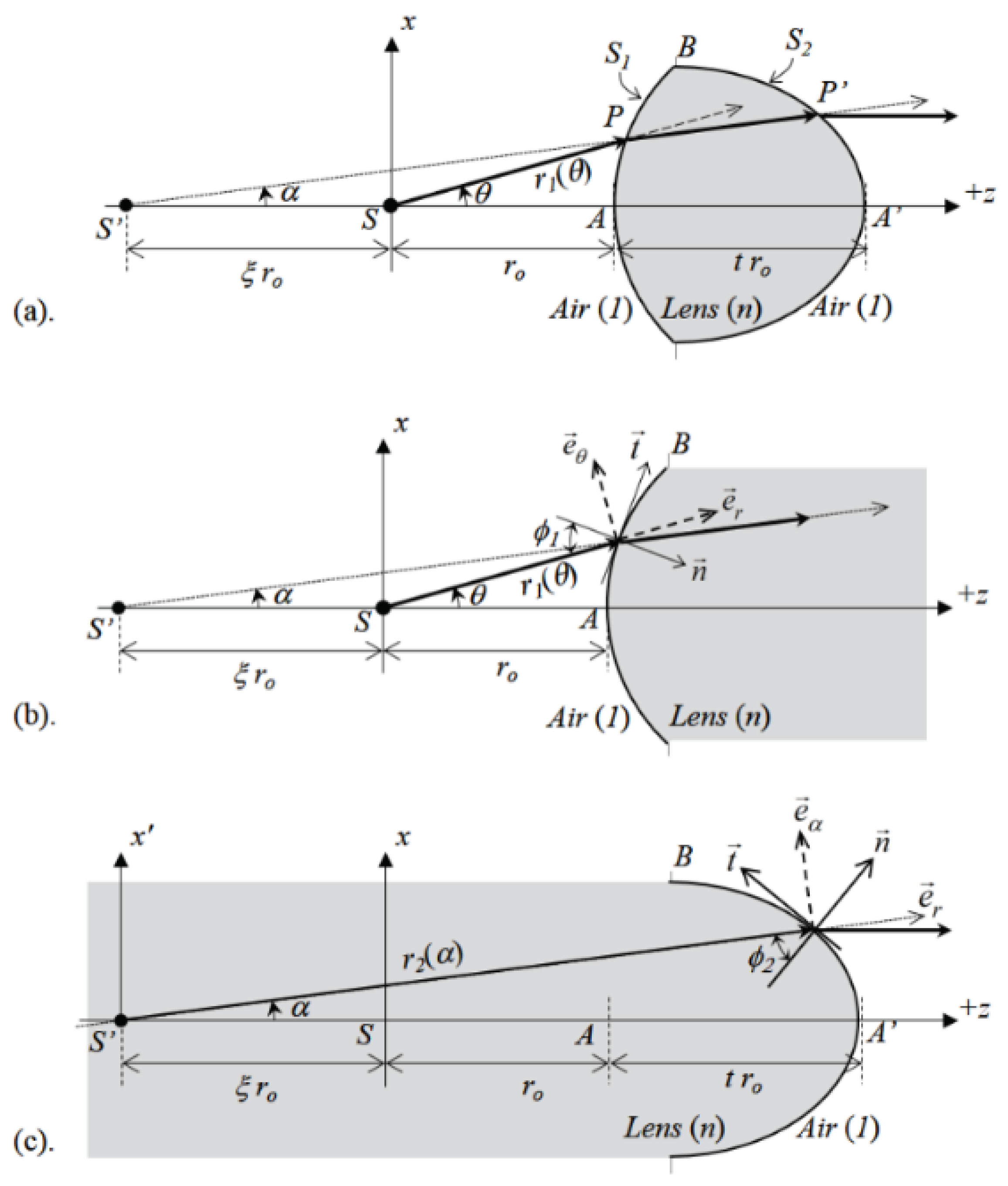
The so-called analytic collimating lens is based on the assumption of an infinitely small point source of light. According to the principles of analytic geometry, polar coordinate system, and Snell’s Law, an axisymmetric lens is designed by mathematical analysis. This lens has two special and aspherical optical surfaces, which can make the light from the coordinate origin be refracted by these two optical surfaces and become collimated light parallel to the optical axis. As shown in Figure A1, a point source is located at the origin of a two-dimensional polar coordinate . The two surfaces of an axisymmetric lens are and . They can be divided into two two-dimensional function of polar coordinates defined by the curve of and . The design principle of this analytic collimating lens is to allow all rays emitted from the origin of the coordinate S to be refracted by the first surface and form a virtual focus at a selected position on the optical axis, as shown in Figure A1. The light starts from this virtual focus and is refracted by the second optical surface so that the direction of the refracted light is parallel to the optical axis of the system.
As shown in Figure A1, three parameters need to be determined when designing this analytic collimating lens: (1) the distance between the center point A of the first surface of the lens and the light source S; (2) the outermost edge position B of the lens or its corresponding maximum cone angle ; (3) the distance between the virtual focus and the light source S is . According to the previous analysis discussed in Ref. [25], it can be proved that the mathematical equations that function and need to comply with are Equations (A1) and (A2); therefore, as long as , , and the optical refraction coefficient n of the lens material are determined, the analytic solution of and can be obtained. This lens can guide all the light rays starting from point S into collimated light rays to achieve the goal of collimation.
Figure A1.
Double-sided analytic collimating lens for collimating light form a point source: (a) Overview, (b,c) details for constructing front () and back () surfaces of the lens.
Figure A1.
Double-sided analytic collimating lens for collimating light form a point source: (a) Overview, (b,c) details for constructing front () and back () surfaces of the lens.

References
- Shiba, S.F.; Tan, J.Y.; Kim, J. Multidirectional UV-LED lithography using an array of high-intensity UV-LEDs and tilt-rotational sample holder for 3-D microfabrication. Micro Nano Syst. Lett. 2020, 8, 5. [Google Scholar] [CrossRef]
- Ding, Y.; Liu, X.; rong Zheng, Z.; Fu Gu, P. Freeform LED lens for uniform illumination. Opt. Express 2008, 16, 12958–12966. [Google Scholar] [CrossRef] [PubMed] [Green Version]
- Luo, Y.; Feng, Z.; Han, Y.; Li, H. Design of compact and smooth free-form optical system with uniform illuminance for LED source. Opt. Express 2010, 18, 9055–9063. [Google Scholar] [CrossRef] [PubMed]
- Zhao, Z.; Zhang, H.; Zheng, H.; Liu, S. New reversing freeform lens design method for LED uniform illumination with extended source and near field. Opt. Commun. 2018, 410, 123–129. [Google Scholar] [CrossRef]
- Kuo, S.H.; Chen, C.F. Design of a collimated UV-LED exposure unit based on light spread function method. Appl. Opt. 2017, 56, 5542–5549. [Google Scholar] [CrossRef] [PubMed]
- Chen, J.J.; Lin, C.T. Freeform surface design for a light-emitting diode-based collimating lens. Opt. Eng. 2010, 49, 093001. [Google Scholar] [CrossRef]
- Chen, J.J.; Wang, T.Y.; Huang, K.L.; Liu, T.S.; Tsai, M.D.; Lin, C.T. Freeform lens design for LED collimating illumination. Opt. Express 2012, 20, 10984–10995. [Google Scholar] [CrossRef] [PubMed] [Green Version]
- Chen, R.S. Investigation of a slope-point-based method for the design of aspheric surfaces in a catadioptric collimating optical system for a light-emitting diode source. Appl. Opt. 2014, 53, H129–H139. [Google Scholar] [CrossRef] [PubMed]
- Grabovičkić, D.; Benítez, P.; nano, J.C.M. TIR RXI collimator. Opt. Express 2012, 20, A51–A61. [Google Scholar] [CrossRef] [PubMed] [Green Version]
- Wang, G.; Wang, L.; Li, F.; Zhang, G. Collimating lens for light-emitting-diode light source based on non-imaging optics. Appl. Opt. 2012, 51, 1654–1659. [Google Scholar] [CrossRef] [PubMed]
- Cheng, H.; Xu, C.; Jing, X.; Tam, H.Y. Design of compact LED free-form optical system for aeronautical illumination. Appl. Opt. 2015, 54, 7632–7639. [Google Scholar] [CrossRef] [PubMed]
- Romanova, G.E.; Qiao, X. Composing method and aberration theory in collimating systems design. In Optical Design and Testing X; Wang, Y., Kidger, T.E., Matoba, O., Wu, R., Eds.; International Society for Optics and Photonics, SPIE: Bellingham, WA, USA, 2020; Volume 11548, pp. 234–240. [Google Scholar] [CrossRef]
- Kumar, H.; Velu, R.; Balasubramanian, E. A novel freeform lens design for collimating UV light emitted from an LED with large divergent angle. Optik 2019, 181, 1039–1048. [Google Scholar] [CrossRef]
- Kari, T.; Gadegaard, J.; Søndergaard, T.; Pedersen, T.G.; Pedersen, K. Reliability of point source approximations in compact LED lens designs. Opt. Express 2011, 19, A1190–A1195. [Google Scholar] [CrossRef] [PubMed]
- Avendaño-Alejo, M.; Román-Hernández, E.; neda, L.C.; Moreno-Oliva, V.I. Analytic conic constants to reduce the spherical aberration of a single lens used in collimated light. Appl. Opt. 2017, 56, 6244–6254. [Google Scholar] [CrossRef] [PubMed]
- Chen, L.C.; Low, A.L.Y.; Chien, S.F. Combinational system of a truncated ball lens and a hyperbolic lens for collimating a highly divergent source. OSA 2004, 43, 6380. [Google Scholar] [CrossRef] [PubMed]
- Logean, E.; Hvozdara, L.; Di-Francesco, J.; Herzig, H.P.; Voelkel, R.; Eisner, M.; Baroni, P.Y.; Rochat, M.; Müller, A. High numerical aperture silicon collimating lens for mid-infrared quantum cascade lasers manufactured using wafer-level techniques. In Optical Systems Design 2012; Mazuray, L., Wartmann, R., Wood, A.P., de la Fuente, M.C., Tissot, J.L.M., Raynor, J.M., Smith, D.G., Wyrowski, F., Erdmann, A., Kidger, T.E., et al., Eds.; International Society for Optics and Photonics, SPIE: Bellingham, WA, USA, 2012; Volume 8550, pp. 228–233. [Google Scholar] [CrossRef] [Green Version]
- Syms, R. Refractive collimating microlens arrays by surface tension self-assembly. IEEE Photonics Technol. Lett. 2000, 12, 1507–1509. [Google Scholar] [CrossRef] [Green Version]
- Zhang, Y.; Yan, G.; Li, Z.; Fang, F. Quality improvement of collimating lens produced by precision glass molding according to performance evaluation. Opt. Express 2019, 27, 5033–5047. [Google Scholar] [CrossRef] [PubMed]
- Yang, H.R.; Weng, T.C.; Tzai, W.J.; Chen, C.H.; Yu, C.C.; Chu, W.Y.; Yoo, S.; Huang, C.J.; Cheng, C.Y. Lithography process controllers and photoresist monitoring by signal response metrology (SRM). In Metrology, Inspection, and Process Control for Microlithography XXIX; Cain, J.P., Sanchez, M.I., Eds.; International Society for Optics and Photonics, SPIE: Bellingham, WA, USA, 2015; Volume 9424, pp. 744–753. [Google Scholar] [CrossRef]
- Miller, D.B.; Forman, D.L.; Jones, A.M.; McLeod, R.R. Super-resolved critical dimensions in far-field I-line photolithography. J. Micro/Nanolithogr. MEMS MOEMS 2019, 18, 013505. [Google Scholar] [CrossRef]
- Giel, B.V.; Meuret, Y.; Thienpont, H. Using a fly’s eye integrator in efficient illumination engines with multiple light-emitting diode light sources. Opt. Eng. 2007, 46, 043001. [Google Scholar] [CrossRef]
- Jiang, H.; Sun, X.; Yang, R.; Chen, J.; Xie, L.; Yin, S. Design of UV LED illumination system for direct imaging lithography. In Optical Design and Testing VIII; Wang, Y., Kidger, T.E., Tatsuno, K., Eds.; International Society for Optics and Photonics, SPIE: Bellingham, WA, USA, 2018; Volume 10815, pp. 195–202. [Google Scholar] [CrossRef]
- Huang, J.W. The illumination design of UV LED array for lithography. In Optical Microlithography XXXI; Kye, J., Ed.; International Society for Optics and Photonics, SPIE: Bellingham, WA, USA, 2018; Volume 10587, pp. 278–285. [Google Scholar] [CrossRef]
- Syu, Y.S.; Wu, C.Y.; Lee, Y.C. Double-Sided Freeform Lens for Light Collimation of Light Emitting Diodes. Appl. Sci. 2019, 9, 5452. [Google Scholar] [CrossRef] [Green Version]
- EVONIK. PLEXIGLAS®8012 Material Manual; EVONIK: Essen, Germany, 2019; Available online: https://corporate.evonik.com/en/ (accessed on 17 December 2021).
Figure 1.
Radiation patterns or optical intensity directivities of the six chosen UV-LEDs (I–VI).

Figure 2.
The analytic collimating lens is designed by: (a) selecting and to determine starting from point A and ended with an aperture angle of , (b) constructing staring from the symbol + and ended at the distance of D relative to point A on the optical axis.
Figure 2.
The analytic collimating lens is designed by: (a) selecting and to determine starting from point A and ended with an aperture angle of , (b) constructing staring from the symbol + and ended at the distance of D relative to point A on the optical axis.

Figure 3.
Analyze rays emitted from a LED chip and refracted by the designed light collimating lens.
Figure 3.
Analyze rays emitted from a LED chip and refracted by the designed light collimating lens.

Figure 4.
Contour maps of the weighted mean divergence angle, , as a function of the two collimating lens parameters, and , for the six UV-LEDs (I–VI).
Figure 4.
Contour maps of the weighted mean divergence angle, , as a function of the two collimating lens parameters, and , for the six UV-LEDs (I–VI).

Figure 5.
(from left to right) The collimating lens profiles, illuminance distribution on the detector plane, and statistics of accumulated power as a function of divergence angle for each of the six (I–VI) UV-LED light sources.
Figure 5.
(from left to right) The collimating lens profiles, illuminance distribution on the detector plane, and statistics of accumulated power as a function of divergence angle for each of the six (I–VI) UV-LED light sources.

Figure 6.
Relationship between the divergence angle and the dimensional factor for each commercial UV-LED light source after light collimation.
Figure 6.
Relationship between the divergence angle and the dimensional factor for each commercial UV-LED light source after light collimation.


Table 1.
Specification of commercial UV-LED.
| Optical Characteristics (Ths = 25 °C) | |||
|---|---|---|---|
| Item | Luminous Area | Luminous Flux | Directivity |
| (mm2) | (mW) | ||
| Luminus | |||
| (I) SST-10-UV | 1 × 1 | 2200–2500 | 120 |
| (II) CBT-120-UV | 4.63 × 2.60 | 14,600–19,500 | 100 |
| Nichia | |||
| (III) NVSU333A | 2 × 2 | 4640 | 138 |
| (IV) NVSU119C | 2 × 2 | 1420 | 110 |
| Seoul Viosys | |||
| (V) CUN0GB1A | 2.8 × 2.8 | 1630 | 60 |
| (VI) CUN06B1B_140516 | 2 × 2 | 1160 | 46 |
Table 2.
Optimized parameters of collimating lenses for the six UV-LEDs and evaluated results.
| Item | Directivity | DF | DA | DA | OE | ||
|---|---|---|---|---|---|---|---|
| (mm) | (%) | ||||||
| I | 120 | 20 | 0.6 | 0.0500 | 1.56 | 4.16 | 50.2 |
| II | 100 | 22 | 2.5 | 0.1643 | 2.20 | 3.44 | 56.6 |
| III | 138 | 12 | 0.1 | 0.1667 | 2.84 | 12.84 | 63.0 |
| IV | 110 | 28 | 0.3 | 0.0714 | 1.62 | 4.56 | 44.8 |
| V | 60 | 26 | 0.7 | 0.1076 | 1.66 | 2.54 | 72.0 |
| VI | 46 | 27 | 0.9 | 0.0740 | 1.58 | 2.30 | 33.8 |
Publisher’s Note: MDPI stays neutral with regard to jurisdictional claims in published maps and institutional affiliations. |
© 2022 by the authors. Licensee MDPI, Basel, Switzerland. This article is an open access article distributed under the terms and conditions of the Creative Commons Attribution (CC BY) license (https://creativecommons.org/licenses/by/4.0/).
Share and Cite
MDPI and ACS Style
Syu, Y.-S.; Lee, Y.-C. Quantitative Evaluation of Light Collimating for Commercial UV-LEDs Based on Analytic Collimating Lens. Appl. Sci. 2022, 12, 911. https://0-doi-org.brum.beds.ac.uk/10.3390/app12020911
AMA Style
Syu Y-S, Lee Y-C. Quantitative Evaluation of Light Collimating for Commercial UV-LEDs Based on Analytic Collimating Lens. Applied Sciences. 2022; 12(2):911. https://0-doi-org.brum.beds.ac.uk/10.3390/app12020911
Chicago/Turabian StyleSyu, Yong-Sin, and Yung-Chun Lee. 2022. "Quantitative Evaluation of Light Collimating for Commercial UV-LEDs Based on Analytic Collimating Lens" Applied Sciences 12, no. 2: 911. https://0-doi-org.brum.beds.ac.uk/10.3390/app12020911
Note that from the first issue of 2016, this journal uses article numbers instead of page numbers. See further details here.