Article

Powder Explosion Inhibitor Prepared from Waste Incinerator Slag: Applied to Explosion Suppression of Oil Shale Dust Explosion

1
College of Resources and Civil Engineering, Northeastern University, Shenyang 110819, China
2
Key Laboratory of Ministry of Education on Safe Mining of Deep Metal Mines, NO. 3-11, Wenhua Road, Heping District, Shenyang 110819, China
*
Authors to whom correspondence should be addressed.
Submission received: 3 January 2022 / Revised: 14 January 2022 / Accepted: 15 January 2022 / Published: 20 January 2022
(This article belongs to the Special Issue Advanced Technologies on Mine Dust Prevention and Control)

Abstract

:
In this paper, a method for waste incineration slag is proposed. An incineration acidification alkalization modification was carried out based on the characteristics of the oxides (SiO2, CaO, Al2O3, Fe2O3, and MgO) of waste incineration slag. With modified slag as the carrier and NaHCO3 as the supporter, a slag-based composite powder explosion inhibitor was prepared with the solvent-crystallization wet coating (WCSC), ball milling dry coating (DCBM), and air impact dry coating (DCAI) methods. The advantages and disadvantages of the three methods were compared and analyzed. Explosion suppression experiments on oil shale dust were carried out, and the explosion suppression mechanism was described. The explosion suppression process of the modified slag–NaHCO3 composite powder explosion inhibitor for oil shale dust was found to involve a synergy of physical and chemical inhibition. This explosion suppression mechanism indicates three requirements for the preparation and application of industrial solid waste-based composite powder explosion inhibitors. The feasibility of preparing composite powder explosion inhibitors from waste incinerator slag was discussed from the experimental point of view and its explosion suppression performance on oil shale dust was studied with the intention of providing a new form of resource utilization for waste incinerator slag.

1. Introduction

A large amount of industrial solid waste (ISW) is produced in the process of industrialization. Some ISW can be used as resources. The resource utilization of solid waste can increase the added value of industrial production, as well as serve the safety of industrial production. Utilizing the resources of ISW and transforming solid waste into economic and safety benefits have remained topics of concern for scientists. This paper is focused on the resource utilization of waste incinerator slag through the preparation of ISW-based composite powder explosion inhibitors and use of them to prevent explosion accidents of mineral dust in the process of industrial production.
Waste incinerator slag, a kind of ISW generated from waste incineration, is a renewable and reusable resource. Waste incinerator slag has been extensively studied throughout the world with respect to its potential use as, e.g., a substitute aggregate for concrete, a raw material for cement, a cover material for landfills, and for making brick or ceramics [1,2]. Waste incinerator slag features a complex physical composition, high strength, good rigidity, higher moisture content, higher water absorbability, smaller apparent density, and greater crushing index in comparison to natural stone [3]. Worldwide, waste incinerator slag is primarily landfilled or otherwise used as filling material for embankments or road bases [4,5].
Tang [6] studied the feasibility of city refuse incinerator slag as auxiliary gel for building materials. Zeng [7] used MSW incineration slag as a substitute for cement and coarse aggregate in concrete.
In terms of preparing explosion inhibitors from solid waste, most research has mixed two or more materials to obtain hybrid composite materials. Wang [8] prepared a Ca (H2PO4)2/RM composite explosion inhibitor with core-shell structure from red mud and Ca (H2PO4) for suppressing aluminum powder explosions. Wang [9] used fly ash and active powder to prepare powder explosion inhibitors for suppressing coal dust explosions. Yan [10] used diatomite and NaHCO3 to prepare powder explosion inhibitors for suppressing aluminum powder explosions.
At present, research on the preparation of composite powder explosion inhibitors with waste incinerator slag is rare, and most of the composite methods of other hybrid composites are mechanical or chemical composite methods [11,12,13]. However, the specific experimental parameters of different materials in the composite process (such as material mass, temperature, mechanical speed, and air flow rate) are affected by the physical and chemical properties of the materials [14,15,16]. Therefore, this paper follows the research conducted for a variety of composite methods studied by previous scholars. In this paper, the preparation method of a slag-based composite powder explosion inhibitor from waste incineration slag is proposed, the advantages and disadvantages of mechanical composite methods (DBCM and DCAI) and a chemical composite method (WCSC) are compared and analyzed. Explosion inhibition experiments on oil shale dust were carried out by using an MSA–NaHCO3 composite powder explosion inhibitor, and the mechanism of the MSA–NaHCO3 composite powder explosion inhibitor for the explosion of oil shale dust was observed. This study provides a new idea and method for recycling waste incinerator slag and dust explosion suppression techniques.

2. Materials and Methods

2.1. Modification

Waste incinerator slag samples were sourced from Domestic Waste Incineration Power Plant of Shandong Qingdao West Coast Kangheng Environmental Energy Co., Ltd., Shandong, China. Table 1 presents the XRF analysis results of these samples. The waste incinerator slag used for this study comprised SiO2, CaO, Al2O3, Fe2O3, MgO, and Na2O. Some elemental Cl was detected in the slag, suggesting that the slag contained a level of dioxin, so the slag needed to be detoxified.
The slag was incinerated in a muffle furnace under 1400 °C for 1 h, which could completely degrade dioxin and detoxify the slag [17,18,19]. Next, the metal oxide in the waste incinerator slag was transformed into metal hydroxide with the acid–base treatment, since metal hydroxides and metal ions can help to suppress dust explosion. This was achieved with the following steps: (1) add 30 g of waste incinerator slag to 100 mL of deionized water, add 150 mL of 6 mol/L HCl, and stir the mixture with a magnetic stirrer at 80 °C for 1.5 h to obtain a metal salt solution; (2) in the metal salt solution, add ammonia water until the PH value is 7.8, add 150 mL of C2H6O, and stir at 50 °C for 1 h; (3) when the material in the solution is precipitated, extract and filter it with deionized water using a vacuum pump; then, dry the filtered mud in a vacuum drying box for 12 h and grind the mud in a ball mill to obtain modified slag (MSA) with a particle size smaller than 75 μm.

2.2. Compounding

According to the literature [20,21,22,23,24], at present, two methods are generally adopted for material compounding. One is the reverse osmosis method, and the other is the mechanical compounding method. In this study, three methods—the solvent-crystallization wet coating (WCSC), ball milling dry coating (DCBM), and air impact dry coating (DCAI) methods—were used for the comparative preparation of slag-based composite powder explosion inhibitors, and the method with the best composite effect was selected for further study.
Slag-based composite powder explosion inhibitors were prepared using each of these three methods and were named as Table 2.
First of all, MSA–NaHCO3 composite powder explosion inhibitors were prepared by using the solubility difference between H2O and C2H6O, namely by WCSC, as shown in Figure 1. First, 100 g of MSA were added to 150 mL of C2H6O, and the mixture was stirred with a magnetic stirrer. Next, 9.6 g of NaHCO3 were dissolved in 100 mL of deionized water (at a temperature of 30 °C) to form an NaHCO3 saturated solution, which was then slowly and uniformly added into the suspension of MSA–C2H6O (at a temperature of 30 °C and speed of 700 r/min). Then, 150 mL of C2H6O were added until the NaHCO3 crystal was completely precipitated from the surface of the slag matrix. After ultrasonic dispersion for 30 min, the precipitate was filtered out, dried in a vacuum oven for 24 h, and then ground into MSA–NaHCO3 composite powder explosion inhibitors with the same grain size (<75 μm).
The process flowchart of DCBM is shown in Figure 2. During preparation, the powders of both components were fully ground, and they were embedded and coated with each other under friction and extrusion. The carrier was then embedded into the pores of the supporter and coated over the supporter. DCBM was carried out with the following procedure. First, the particle size of NaHCO3 was controlled at below 5 μm with the ball milling screening method. MSA and NaHCO3 were placed in a vacuum drying oven and dried at 30 °C for 12 h. Next, 100 g of MSA and 100 g of NaHCO3 were weighed, placed together into the steel tank, and ground at 500 r/min for 5 min. Then the finished product was taken out, and the excess NaHCO3 was screened out through a 10 μm sieve to yield the DCBM-MSA–NaHCO3 composite powder explosion inhibitor. Samples from the first and second operations were disposed as waste from machine washing; that from the third operation was used as the finished product.
The process flowchart of DCAI is shown in Figure 3. Under the intense impact of high-speed air flow, particles of the two components of the composite inhibitor rubbed and collided with each other, and they were coated on each other under mechanical impact. DCAI was carried out with the following procedure. First, the particle size of NaHCO3 was controlled at below 5 μm with ball milling and screening. MSA and NaHCO3 were placed in a vacuum drying oven and dried at 30 °C for 12 h. Then, 25 g of slag and 25 g of NaHCO3 were weighed, placed together into the dust bin, and impinged under 0.5 MPa at an air flow rate of 0.20 m3/min for 10 min. The finished product was taken out, and the excess NaHCO3 was screened out through a 10 μm sieve to yield the DCAI-MSA–NaHCO3 composite powder explosion inhibitor. Samples from the first and second operations were disposed as waste from machine washing; that from the third operation was used as the finished product.
In order to find the best preparation method with the best compound effect, a variety of slag-based composite powder explosion inhibitors were characterized. Through MSE and nitrogen adsorption–desorption experiments, the compounding effects of various slag-based composite powder explosion inhibitors were analyzed and obtained.

2.3. Material Characterization

Figure 4 shows that the particle size of the MSA–NaHCO3 composite powder explosion inhibitor prepared with the three methods was about 40 μm. Figure 4c shows the MSA–NaHCO3 composite powder explosion inhibitor prepared with the WCSC method. Compared to the original MSA, the composited inhibitor was fully coated, and the pores of the MSA were coated and filled up by NaHCO3; Figure 4d shows the MSA–NaHCO3 composite powder explosion inhibitor prepared with the DCBM method. There were a few pores on its surface, but the product was well-coated at large; Figure 4e shows the MSA–NaHCO3 composite powder explosion inhibitor prepared with the DCAI method. There were many pores on its surface, and these were obviously filled by NaHCO3. Accordingly, the SEM diagrams show that the composite powder explosion inhibitor prepared with the WCSC method was the most efficacious.
Table 3 shows that the specific surface areas and pore volumes of the three kinds of MSA–NaHCO3 composite powder explosion inhibitors were smaller than those of MSA, because NaHCO3 could be effectively compounded to MSA after the compounding process. As shown in Figure 5, the nitrogen adsorption–desorption isotherm curve of MSA shows an IV-H2(a) hysteresis loop in IUPAC classification, indicating that MSA has relatively uniform pores [25,26]. The WCSC-MSA–NaHCO3 composite powder explosion inhibitor presents a type III isothermal curve. Combined with Figure 4 (SEM), it can be seen that the WCSC-MSA–NaHCO3 composite powder explosion inhibitor was a non-porous material. The isotherm curve of DCBM-MSA–NaHCO3 composite powder explosion inhibitor shows an IV-H2(a) hysteresis loop. In comparison with the III curve of the WCSC-MSA–NaHCO3 composite powder explosion inhibitor, DCBM-MSA–NaHCO3 contained a certain amount of pores and its composite effect was relatively poor. The SEM analysis revealed that this method could still achieve an ideal composite state. The nitrogen adsorption–desorption isothermal curve of DCAI-MSA–NaHCO3 composite powder explosion inhibitor is characterized by an IV-H3 type hysteresis loop in IUPAC classification, which indicates a flat slit structure, cracks, and wedge structures, as well as broader hysteresis loops compared to the isothermal curve of the DCBM-MSA–NaHCO3 composite powder explosion inhibitor [27]. Considered in tandem with the results in Figure 4 (SEM), it can be concluded that the composite powder produced by DCAI method was less efficacious than the DCBM method.
From the preparation principle of the three preparation methods, the following conclusions could be drawn: the advantages of the WCSC method are that the supporter can fully enter the pores of the carrier and the composite effect is better. The disadvantage is that the supporter must be easily soluble, which limits many insoluble carriers with good performance. The DCBM and DCAI methods lead to the compounding of more carriers and supporters. The DCBM method leads to better mechanical composite strength but smaller yield. The DCAI method has greater yield but lower mechanical composite strength. The results of experimental analysis could verify these conclusions.
The microscopic states of the composite powder explosion inhibitors prepared with the three methods were compared. The composite inhibitor prepared with the WCSC method was the best composited, with the highest level of coating. For the dry coating method, the composite state and coating degree of the composite powder explosion inhibitors prepared with the DCBM method were better than those prepared with the DCAI method. In order to facilitate the experimental study of the suppression of oil shale dust explosion with slag-based composite powder explosion inhibitors, an MSA–NaHCO3 composite powder explosion inhibitor was prepared with the WCSC method.

3. Results and Discussion

3.1. Introduction of Experimental Instruments

In this study, according to Chinese national standard GB/T 16425, a standard 20 L spherical explosion system was used to carry out the explosion suppression experiment, as shown in Figure 6. The device consisted of three main parts: a main sphere, a control system, and a data acquisition system [28]. During the experiment, a 10 KJ chemical igniter was installed at the center of the ignition electrode in the 20 L spherical tank, and then the 20 L spherical tank was closed. A given weight of dust was placed in the dust bin, the explosion chamber was vacuumed to 0.06 MPa, and the dispersion pressure was set to 2.0 MPa. When the solenoid valve between the dust storage container and the test chamber opened automatically, air and dust were sprayed into the explosion chamber and ignited after a delay of 60 ms. An oil shale dust concentration of 500 g/m3, which had the strongest explosion index, was chosen as the experimental explosion suppression concentration. During the experiment, 10 g of oil shale were mixed with MSA, MSA–NaHCO3, and NaHCO3 and tested according to the material ratio and experimental parameters shown in Table 4. The experiment started with the smallest dose of the inhibitor and increased thereafter at regular intervals. Each experiment was repeated three times. The results of the group of 20 L spherical explosion characterization experiments with the largest maximum explosion pressure (Pmax) and the largest maximum explosion pressure rise rate (dP/dt)max were further analyzed.
The explosion flame propagation was characterized with a transparent pipeline explosion propagation test system. The main pipe of the experimental system was 3 m long and 0.15 m in diameter. The entire test system included a powder sprayer system, an igniter system, a data collection system, a high-speed camera, and a pipeline system, as shown in Figure 7. The air transmission switch was turned on to let compressed air into the air cylinder until the rated power injection pressure (1 MPa) was reached. The ignition energy parameter (E = 20 J) and ignition delay time (t = 25 ms) were set. When the control system began to work, the solenoid valve was opened. The compressed air sprayed the dust in the dust bin into the pipeline through the dispersion valve and evenly dispersed the dust into the pipeline space. After the time delay, the ignition system excited ignition, and the target powder was ignited.
As the mass of mixed dust changed with the addition of the inhibitor, it was necessary to use a high-speed photography to debug various parameters (primarily the initial ignition energy E, ignition time delay t, and initial spray pressure P0) to keep the mass concentration of the dust unchanged while exploding in the pipeline. As shown in Figure 8, before ignition, the dusting length of pure oil shale dust at 20 ms reached 1 m. After 20 ms, the dust cloud began to segment in the pipeline and a lot of dust was deposited at the bottom of the pipeline. Thus, if ignition began at that time, the dust cloud could not fully participate in the explosion reaction. Therefore, experimenting with parameters for complete dust cloud state could ensure the best state of dust explosion. As calculated, the explosion concentration of 9 g of oil shale dust in the pipeline at 20 ms was 509 g/m3. In order to control the explosion concentration of mixed dust in the pipeline to around 500 g/m3, the experimental parameters of mixed dust were debugged using high-speed photography, and experimental parameters shown in Table 2 were obtained.
During the experiment, the oil shale was mixed with MSA, MSA–NaHCO3, and NaHCO3, and these mixtures were tested according to the material ratio and experimental parameters shown in Table 5. The experiment started with the smallest dose of the inhibitor and increased thereafter at regular intervals. Each experiment was repeated three times. The result of the group of flame propagation characterization experiments with the longest flame was further analyzed.

3.2. Experimental Study on Suppression Characteristics of Explosion Pressure of Oil Shale Dust by 20 L Spherical Explosion System in Enclosed Space

In this experimental study, the explosion dust was oil shale dust. The explosion inhibitors were MSA, NaHCO3, and MSA–NaHCO3 composite powder explosion inhibitors at inhibitor equivalents of 0%, 10%, 20%, 30%, 40%, 50%, 60%, etc., until the explosion stopped. The mixing methods were the grinding and screening mixing methods. The dust was poured into the grinding apparatus in proportion and ground in a Chinese planetary ball mill (TC-XQM4) at 400 r/min for 4 min. Then, according to the Taylor standard screening method, the ground dust was screened and the mixed dust with a particle size of less than 75 μm was prepared. Using the air conditioning system of the laboratory, the environmental conditions of the experiment were limited to: a room temperature of 27 °C, an relative air humidity of 67%, and an atmospheric pressure of 99.1 KPa. An explosion pressure change curve was obtained, as shown in Figure 9. Adding more than 30% MSA–NaHCO3 composite powder explosion inhibitor was able to completely inhibit the explosion of oil shale dust. Adding 30% MSA or NaHCO3 was less effective in suppressing the explosion pressure of oil shale dust than adding a 30% MSA–NaHCO3 composite powder explosion inhibitor, with a maximum pressure drop of 53.2% for the MSA–NaHCO3 composite powder explosion inhibitor, 50.6% for NaHCO3, and 47.8% for MSA. Under the same proportion, the inhibition effect of the three substances on oil shale dust explosion was ranked as: MSA–NaHCO3 composite powder explosion inhibitor >NaHCO3 > MSA.

3.3. Experimental Study on Flame Suppression Characteristics of Oil Shale Dust Explosion by Explosion Inhibitor in Semi Open Space

Dust explosion behavior tests were conducted in a transparent pipeline explosion propagation system by mixing oil shale dust with an MSA–NaHCO3 composite powder explosion inhibitor, MSA, and an NaHCO3 composite powder explosion inhibitor.
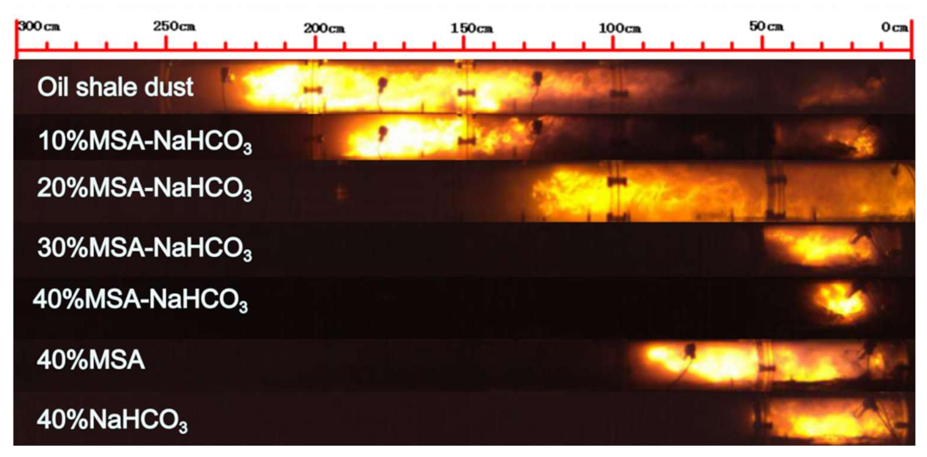
As shown in Figure 10, the maximum explosion flame length of the pure oil shale dust was 2.2 m; the flame front was regularly shaped, continuous, and clearly outlined, and the flame was highlighted [29,30,31]. After adding explosion inhibitors, the flame length was obviously shortened, the flame speed decreased, and a little explosion delay occurred. As the amount of slag-based composite powder explosion inhibitor increased, the explosion flame front of the oil shale dust changed from parabolic to discrete. The isolation coating by the inhibitor on the oil shale particles during the explosion caused the particles to combust and become discrete. The flame length of oil shale dust reduced with increasing amount of slag-based composite powder in all cases. Under the effect of the MSA–NaHCO3 composite powder explosion inhibitor, the flame of oil shale dust was completely suppressed when more than 40% was added; the flame length decreased with the increase of the addition amount of composite powder explosion inhibitor in the range of 0~50%. The suppression effect of pure powder on the flame of oil shale dust was ranked as: NaHCO3 > MSA.
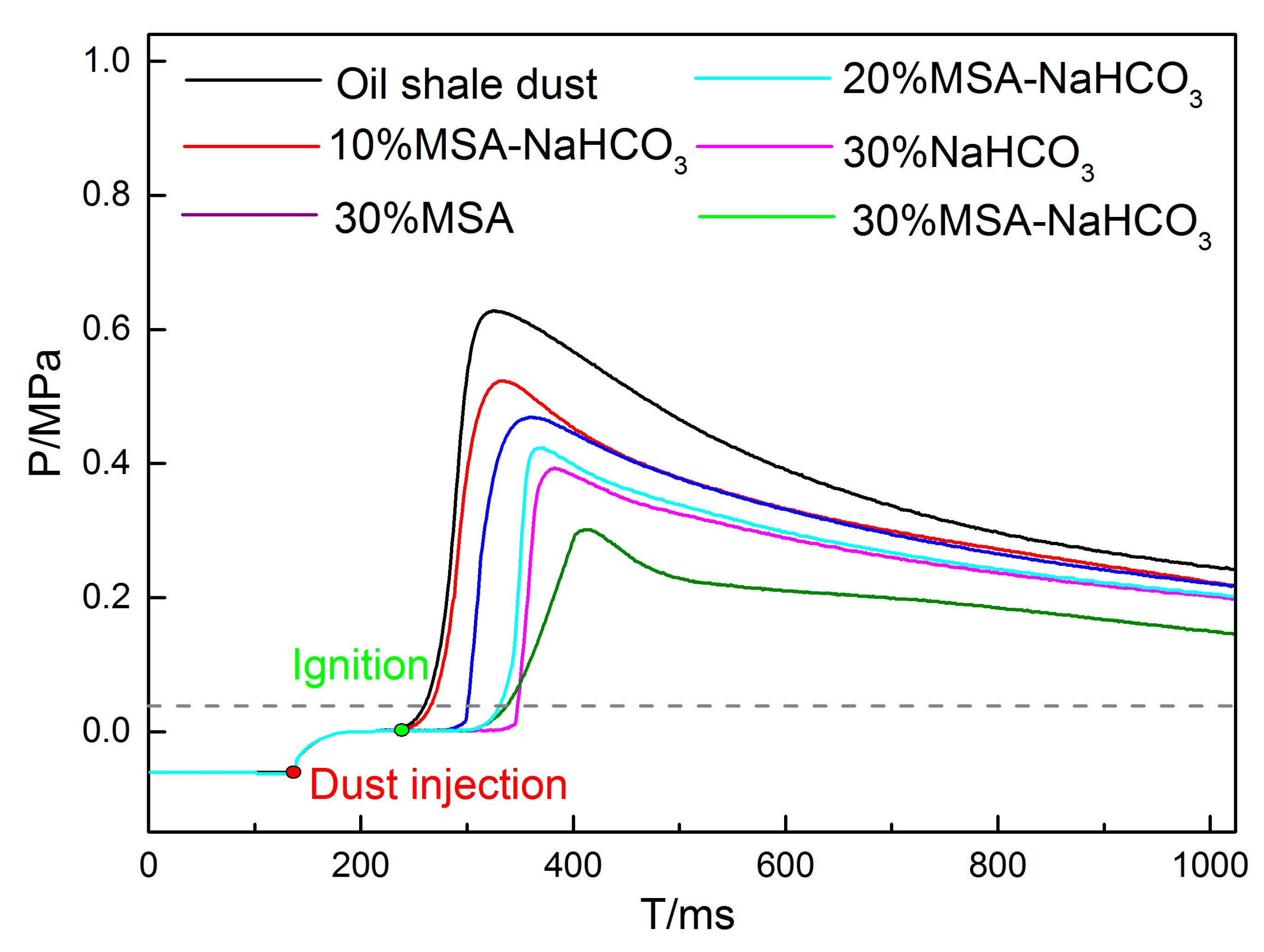
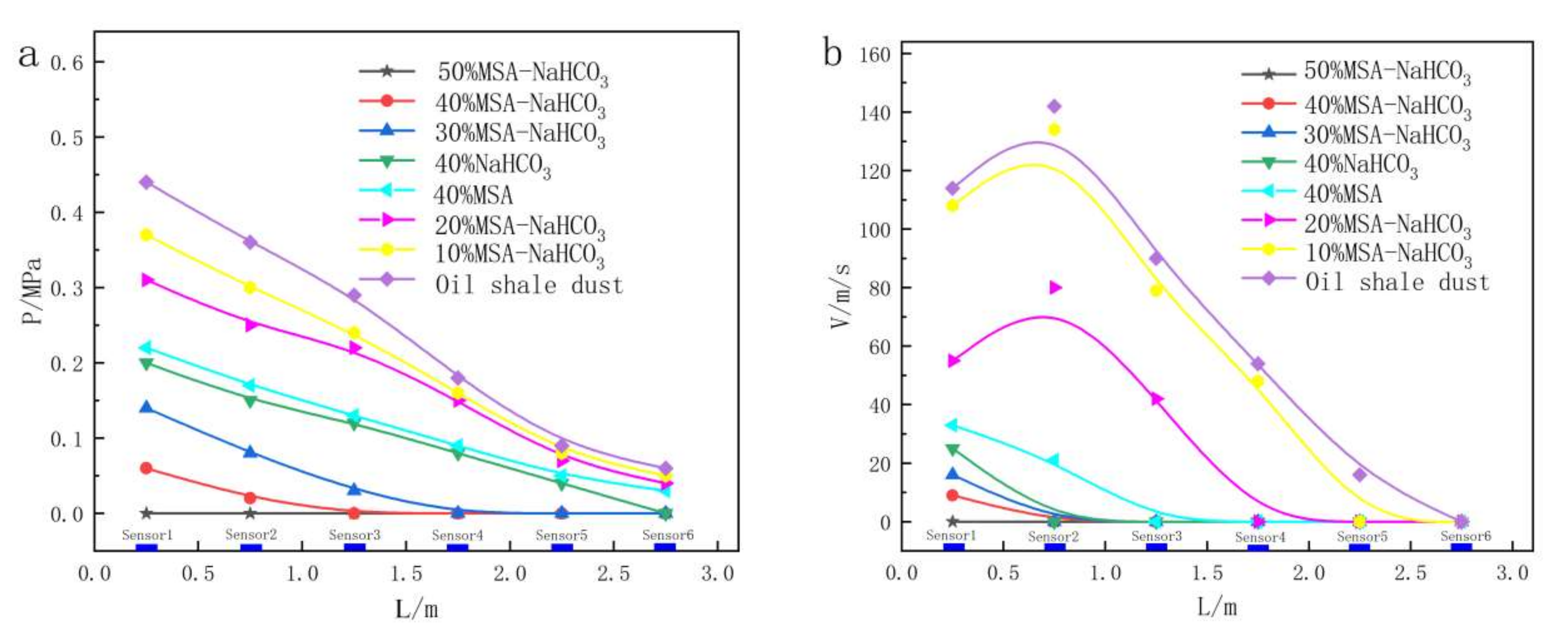
According to the data measured by individual pressure sensors, taking the maximum pressure as the pressure value of that pressure wave passing through the measuring point, the discrete curve graphs of the explosion pressure variation of the mixed dust were generated, as shown in Figure 11a. After the oil shale dust was ignited, due to the large amount of reaction products generated by the oil shale dust, the combustion products were extensively released within a short time, thus creating a pressure inside the pipeline space. With the continuous advancement of the pressure, a pressure wave was formed. In the ignition stage, the pipeline pressure gradually rose and was acquired by pressure sensor 1 at 0.2 m. The pressure value at this point represented the maximum explosion pressure of oil shale dust: 0.46 MPa. As the explosion went on, the amount of shale dust involved in the explosion reduced. The explosion products decreased. The pressure released in the pipe space gradually dropped. The pressure wave was also weakened by the resistance of the pipe wall: the pressure measured by sensor 5 at 2.2 m dropped to 0.13 MPa. Adding explosion inhibitors to the shale dust slowed down its combustion reaction, limited the explosion participation of the shale dust, and reduced the reaction substances produced by explosion, thus bringing down the pressure value in the pipeline. The data show that 40% MSA–NaHCO3 changed the maximum explosion pressure of the shale dust to 0.08 MPa and the maximum explosion pressure drop rate to 82.6%. In the experiment, a high-speed camera was used to acquire flame propagation images. The MATLAB program based on the Roberts operator was used to extract the edges of the dust flames. The flame propagation speed was obtained by changing the horizontal position of the flame front, as shown in Figure 11b. The pressure wave of the mixture began to gradually decrease as the explosion started. The initial flame propagation speed gradually increased. The flame propagation velocity reached its maximum near 0.75 m and then began to tend down. Furthermore, it can be seen that the maximum explosion pressure and flame propagation speed of the mixture significantly decreased after adding different mass fractions of MSA–NaHCO3, and adding a 50% mass fraction of the MSA–NaHCO3 mixture was able to completely inhibit the explosion of the oil shale dust.

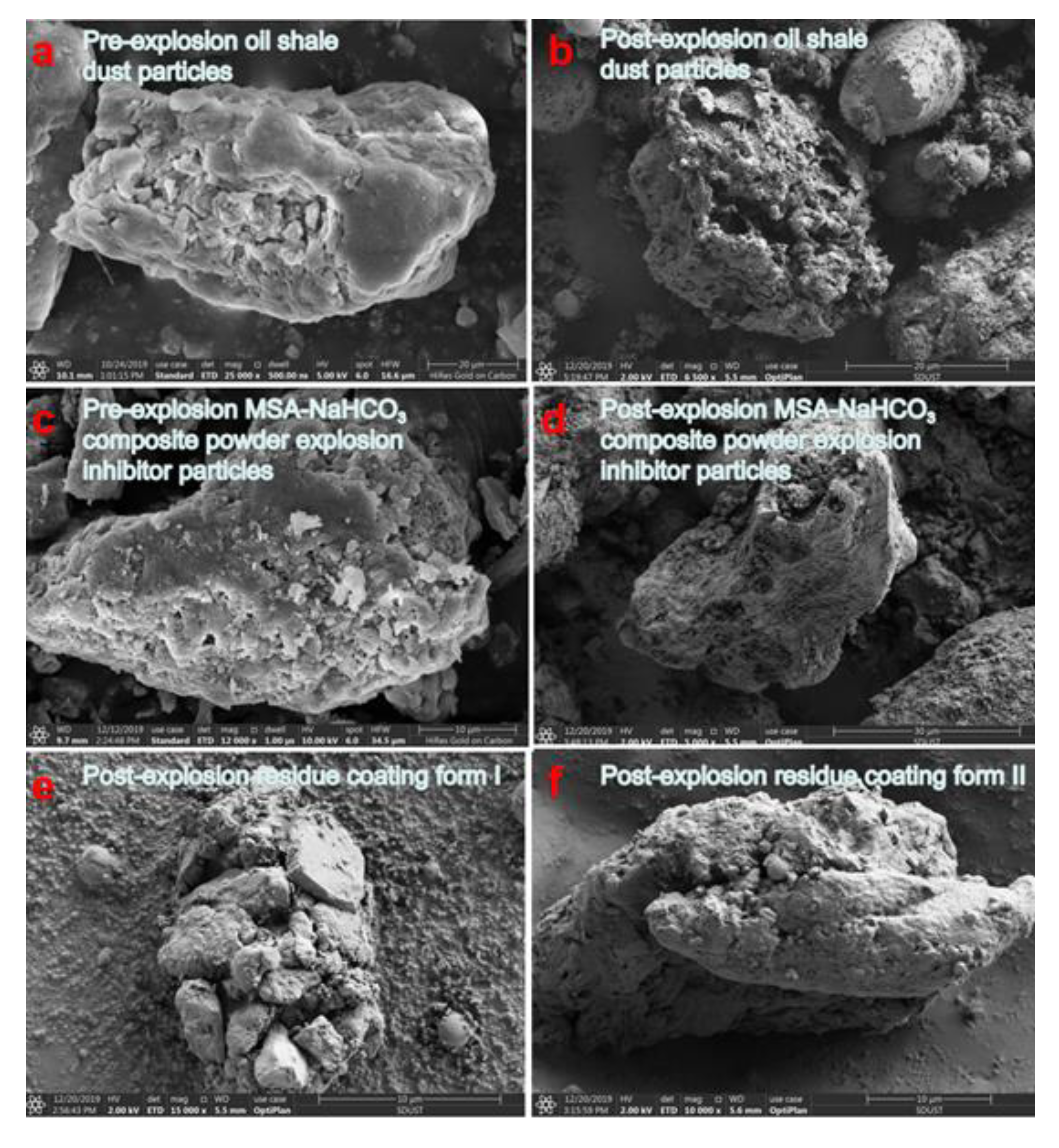
3.4. Analysis of Explosion Residues

Figure 12b shows post-explosion oil shale dust particles. Compared to the pre-explosion oil shale dust particles in Figure 12a, the post-explosion oil shale dust particles are fragmented in shape with developed pores. During the explosion of the oil shale dust, its volatile content was separated and participated in the combustion. After it combusted together with coke, the explosion residues were mostly inorganic skeletons such as SiO2. Figure 12d shows post-explosion MSA–NaHCO3 composite powder explosion inhibitor particles. Compared to the unexploded MSA–NaHCO3 composite powder explosion inhibitor particles in Figure 12c, the exploded particles in Figure 12d were irregular in shape. The inhibitor particles were crushed under external forces; the NaHCO3 originally coated on the MSA was thermally decomposed during the explosion. Hence, MSA skeletons could be detected in the post-explosion MSA–NaHCO3 composite powder explosion inhibitor. Figure 12e,f shows the explosion residues, in which the inhibitor particles and the oil shale particles were bonded and coated with each other. This inhibition effect can also be called a physical coating effect. Physical coating can effectively weaken the thermal radiation and thermal conduction of oil shale particles caused by heat sources in an explosion environment, thus reducing the heat of the oil shale particles and limiting the separation of the volatile content in the oil shale particles and the probability of the oil shale particles being ignited by external heat sources. The flame state of an oil shale dust explosion can also verify the coating effect in the suppression behavior of powder inhibitors on oil shale explosions.
In order to study the formation of reactive substances during explosions, the explosion products were collected following the 20 L spherical explosion experiment. The explosion products included gas and solid products. Gas products were collected with a gas collection device within 30 s after the explosion experiment. The composition of the gas after explosion was analyzed with a GC–MS-QP2010 Ultra, a Japanese SHIMADZU gas chromatography–mass spectrometry (GC–MS). Solid products were collected after the explosion test. The composition of solid products was detected with an EDX 4500H XRF tester produced by Skyray Instrument. The material composition of the main explosion products is tabulated in Table 6. The GC–MS analysis of the gas products showed that, for pure oil shale dust and the mixed dust with an inhibitor, the main gas products were CO2, NO2, CO, and SO2. After adding the 20% MSA–NaHCO3 composite powder inhibitor, the CO2 content in the gas mixture produced by the mixed dust explosion increased by 5.2% and the content of CO increased by 2.2%. As shown in Formula (1), the explosion suppression effect of the explosion inhibitor reduced the amount of oil shale dust participating in the explosion or made the combustion reaction insufficient, resulting in a lower CO2 content and a higher CO content.
C n H m + 2 O 2 underreaction C n 2 H m 2 + CO + CO 2 + H 2 O
At the same time, as the NaHCO3 in the explosion inhibitor generated CO2 in the explosive environment, the CO2 content in the explosion products did not increase much, as shown in Formula (4). The XRF analysis of the solid products showed that before adding the 20% MSA–NaHCO3 composite powder explosion inhibitor, the mixed dust was primarily composed of SiO2, Fe2O3, Al2O3, and CaO. After adding the mixed dust explosion inhibitor, the Fe2O3 and Al2O3 contents in the gas products were slightly increased. The pyrolysis endothermic effect of metal hydroxides in the inhibitor, such as Al(OH)3 and Fe(OH)3, gave rise to metal oxides such as Al2O3 and Fe2O3, thus adding to the Fe2O3 and Al2O3 contents.
In order to study the chemical reaction forms in the process of the explosion, the types of functional groups in the pre-explosion and post-explosion dust samples were tested using a Vertex70 Fourier transform infrared spectrometer (FTIR) (Bruker). The 400–4000 cm−1 waveband of the infrared spectrum was selected [32].
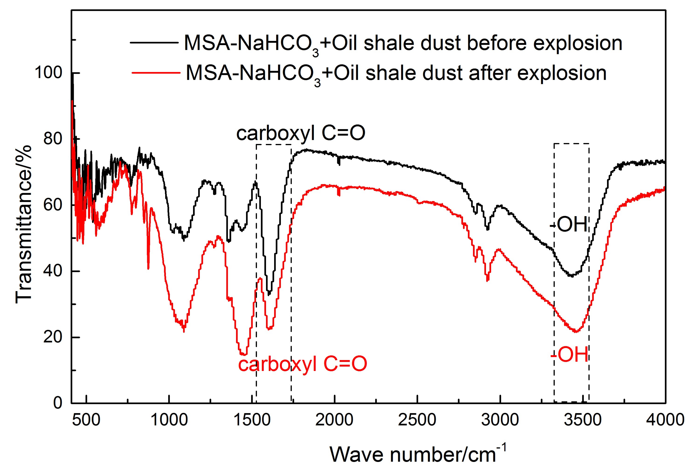
Figure 13 shows the FTIR analysis results of the suppression behavior of the MSA–NaHCO3 composite powder explosion inhibitors on industrial dust explosions. The FTIR analysis results indicate that, after MSA–NaHCO3 composite powder explosion inhibitor was added, the explosion residue of the oil shale dust contained a C = O stretching vibration of carboxyl group near 1600 cm−1 in all cases. After the explosion, the vibration peak intensity reduced and the stretching vibration of the carboxyl group occurred near 3500 cm−1. The vibration peak intensity increased a little after the explosion because NaHCO3 participated in the reaction during the explosion and were decomposed into NaOH, CO2, and H2O. The CO2 and H2O were evaporated; the C=O of the carboxyl group reduced and the carboxyl increased. In the process of explosion suppression, the MSA–NaHCO3 composite powder explosion inhibitor generated gas, which competed for space with oxygen in a limited space and helped reduce the oxygen concentration in the explosion environment, known as the gas inerting effect.
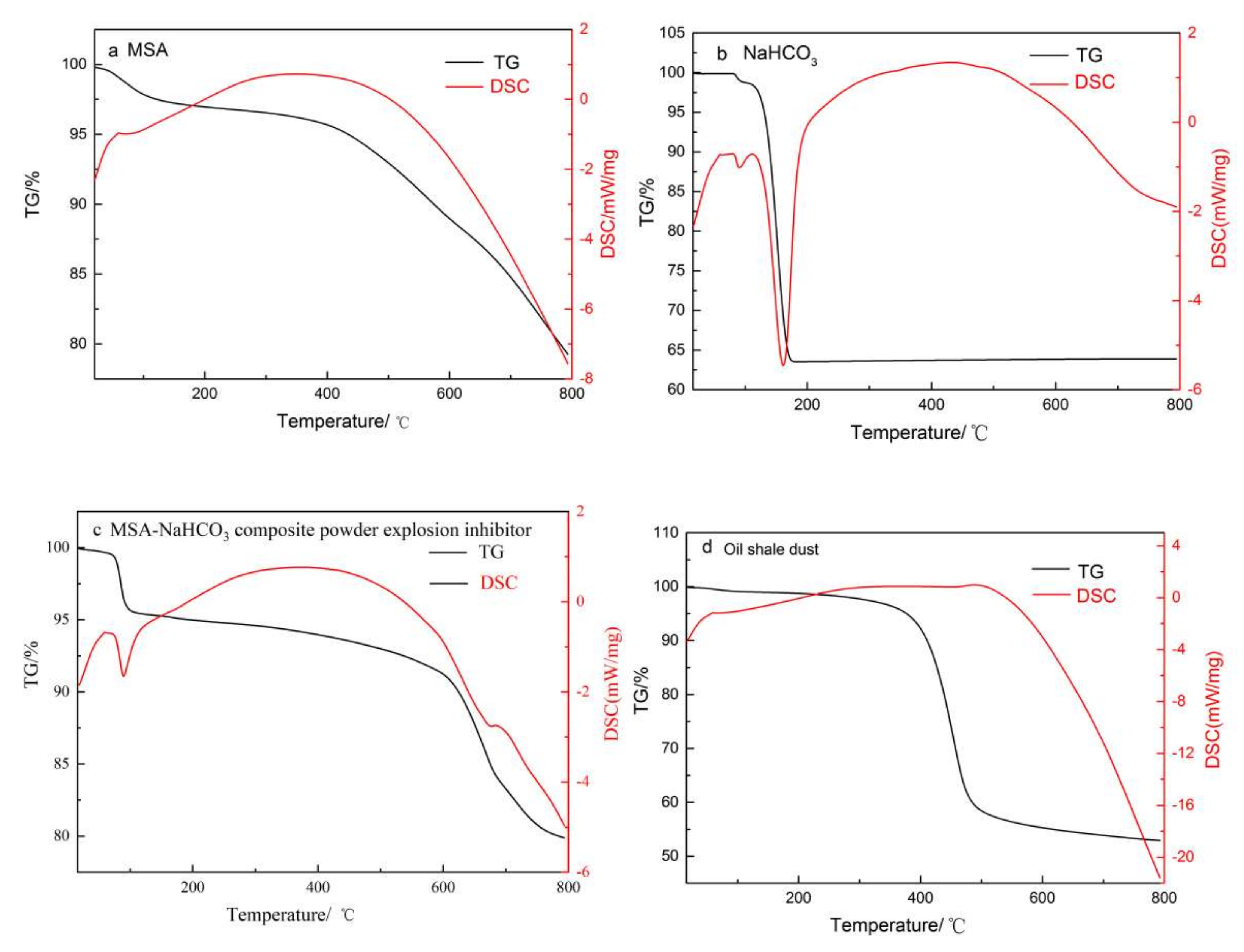
Meanwhile, in order to study the explosion suppression mechanism of the MSA–NaHCO3 composite powder explosion inhibitor, the explosion suppression mode was thermogravimetrically analyzed. MSA, NaHCO3, and MSA–NaHCO3 composite powder explosion inhibitors, as well as oil shale dust, were thermogravimetrically analyzed using an STA PT 1600 simultaneous thermogravimetric analyzer (TGA) across a temperature range from room temperature to 800 °C increased at an interval of 10 °C/min. The results are presented below.
Figure 14a shows the TG–DSC curve of MSA, which shows that 50–120 °C was the endothermic decomposition of H2O in MSA and 200–600 °C was the endothermic pyrolysis of Al(OH)3, Fe(OH)3, and other metal hydroxides in MSA when forming metal oxides such as Al2O3 and Fe2O3. Figure 14b shows the TG–DSC curve of NaHCO3. The TG curve shows that the mass loss began at about 100 °C and tended to be stable after 186 °C, so NaHCO3 was in the thermal decomposition stage at 100–186 °C. The DSC curve shows two endothermic peaks: at 100 °C, the NaHCO3 crystal melted and absorbed heat; 161 °C corresponds to a strong endothermic peak at which NaHCO3 was decomposed into NaOH, H2O, and CO2 and absorbed a large amount of heat. As shown in Figure 14c, the TG curve of the MSA–NaHCO3 composite powder explosion inhibitor contains three steps: 16–100 °C corresponds to moisture decomposition in MSA;,100–200 °C corresponds to the decomposition of NaHCO3 (as can be proven by FTIR analysis in Figure 13), and the pyrolysis reaction of metal hydroxide in MSA occurred at 200–800 °C to form metal oxides. The DSC curve contains two endothermic peaks, mainly corresponding to the endothermic decomposition of NaHCO3 and metal hydroxides. Obviously, the MSA–NaHCO3 composite powder explosion inhibitor effectively combined the cooling effects of MSA and NaHCO3. Figure 14d shows the thermogravimetric curve of oil shale dust. The TG curve shows a slow weight loss at 50–250 °C, indicating the gradual moisture evaporation in oil shale; 250–550 °C corresponds to combustion-induced weight loss; 550–800 °C marks the end of combustion when the curve begins to stabilize. The DSC curve shows an exothermic peak at 489 °C, suggesting that oil shale dust had the highest combustion reaction speed and the greatest exothermic capacity at 489 °C. This comparative analysis confirms that the optimal pyrolysis temperature range of the MSA–NaHCO3 composite powder explosion inhibitor is 100–200 °C. During explosion suppression, before the oil shale dust reached the peak pyrolysis temperature of 489 °C, the composite inhibitor was able to cool the explosion environment of oil shale dust and keep the ambient temperature from reaching the optimal exploding temperature of oil shale dust. This inhibition effect can also be called physical endothermic cooling effect.
Based on the SEM, FTIF, and TGA results, it can be seen that the explosion suppression process of the MSA–NaHCO3 composite powder explosion inhibitor involves a synergy of physical inhibition and chemical inhibition.
The physical inhibition is mainly reflected in the following three aspects. The first is physical coating: MSA and the metal hydroxides (e.g., Al(OH)3 and Fe(OH)3) in MSA generate metal oxides (e.g., Fe2O3 and Al2O3) to coat the exploded particles. Second is physical endothermic cooling: this refers to the endothermic properties of the metal hydroxides (e.g., Fe(OH)3 and Al(OH)3) in MSA and the NaHCO3 content in the MSA–NaHCO3 composite powder explosion inhibitor. The third is gas inerting: the CO2 produced by the pyrolysis of NaHCO3 and the water vapor formed by H2O compete with O2 in limited environment.
The explosion suppression process of the MSA–NaHCO3 composite powder explosion inhibitor involves material reactions related to physical inhibition:
2 Fe ( OH ) 3 Pyrolysis Fe 2 O 3 + 3 H 2 O
2 Al ( OH ) 3 Pyrolysis Al 2 O 3 + 3 H 2 O
2 NaHCO 3 Pyrolysis Na 2 CO 3 + H 2 O + CO 2
Na 2 CO 3 Pyrolysis Na 2 O + CO 2
Na 2 O + H 2 O 2 NaOH
Chemical inhibition is achieved through homogeneous and heterogeneous reactions of solid inhibitor particles after entering the combustion–explosion region, as well as multiple chain reactions with the free radicals subject to combustion–explosion chain reaction. These reactions consume the key free radicals O and OH that maintain the combustion–explosion chain reaction and limit the exothermic reaction between the free radicals H , OH , and O , thus inhibiting the combustion–explosion reaction.
The explosion of oil shale dust is a process of devolatilization–homogeneous combustion and heterogeneous combustion, in which the volatile content is separated and mixed with oxygen to cause combustion [33,34,35]. The explosion chain reactions resulting from the mixing of the volatile content in the oil shale with oxygen typically include:
C n H m C n H m 1 + H
C n H m + O 2 C n H m 1 + OH
C n H m + OH C n H m 1 + H 2 O
H + O 2 OH + O
C n H m 1 + O 2 HCO + H 2 O
HCO + OH CO + H 2 O
The reactions of the free radicals in the inhibitor with those subject to explosion chain reaction typically include:
HCO + OH CO + H 2 O
OH + O H 2 O

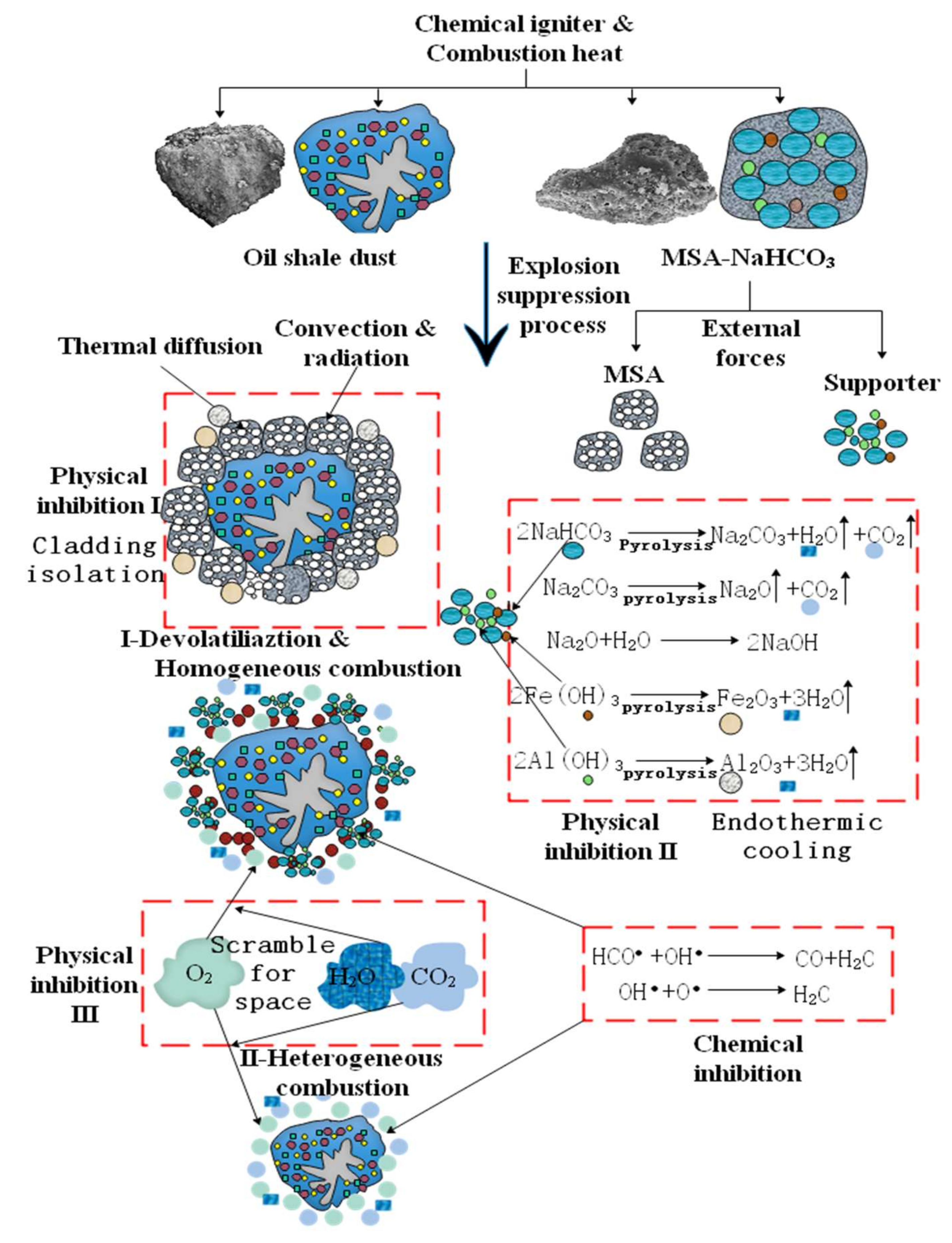
3.5. Inhibition Mechanism of MSA–NaHCO3 Composite Powder Explosion Inhibitor on Oil Shale Dust Explosion

A physical model suitable for describing the suppression effect of the MSA–NaHCO3 composite powder explosion inhibitor on oil shale dust explosion, as shown in Figure 15, was built based on the explosion mechanism of oil shale dust while taking into account the suppression behavior of the inhibitor during explosions. Firstly, the oil shale dust and MSA–NaHCO3 composite powder explosion inhibitor form a dust cloud. Then, after being excited by external energy, the two dusts are heated by external energy at the same time. The oil shale dust is decomposed into shale oil and volatile matter by heating, which combines with oxygen in the air to trigger combustion reaction. The explosion reaction takes place in two different explosion paths: devolatilization–homogenous combustion and heterogenous combustion. Under the action of the explosion shock wave, the explosion inhibitor particles are broken and separated into MSA, NaHCO3, and metal hydroxides in MSA. The oil shale particles are coated by fine MSA, which can prevent the oil shale particles from radiation heating, thus playing the role of coating isolation. The decomposition of NaHCO3 and metal hydroxides in MSA is endothermic, and large amounts of NaOH, CO2, H2O, and Fe2O3 are generated in the decomposition reaction, which plays the role of endothermic cooling. CO2 and H2O compete for space with O2 in limited environment and play the role of gas inerting. During devolatilization–homogenous combustion and heterogenous combustion, the free radical HCO• in NaHCO3 and the OH• in NaOH, Fe(OH)3, and Al(OH)3 consume the key free radicals O• and OH• that maintain the combustion–explosion chain reaction, playing the role of chemical inhibition.
From the inhibition mechanism of the MSA–NaHCO3 composite powder explosion inhibitor on oil shale dust explosion, it can be seen that when preparing and applying ISW-based composite powder explosion inhibitors, attention must be paid to the following three points. (a): When selecting the supporter, remember to select a material with good pyrolysis cooling effect and the ability to produce inert gases—in this way, the effects of endothermic cooling and gas inerting can be effectively exerted in the process of explosion suppression. (b): When selecting the carrier and the supporter, remember to select a material with strong viscosity after explosion, as this can effectively play the role of coating isolation. (c): When using an ISW-based composite powder explosion inhibitor to suppress the explosion of a certain powder, the pyrolysis cooling point of that inhibitor must be lower than the optimal exploding temperature of the explosion suppression object as much as possible, as this can limit the explosion environment temperature to below the optimal exploding temperature of dust.

4. Conclusions

(1)
The feasibility of preparing an ISW-based composite powder explosion inhibitor from waste incineration slag was verified. An MSA–NaHCO3 composite powder explosion inhibitor with good composite effect can be prepared with the WCSC method after waste incinerator slag is modified.
(2)
An MSA–NaHCO3 composite powder explosion inhibitor was used to carry out macroscopic explosion suppression experiments on oil shale dust. The results showed that, in the closed environment of a 20 L spherical explosion apparatus, the optimal dose of the MSA–NaHCO3 composite powder explosion inhibitor for inhibiting the explosion of oil shale dust is 40%. In the semi-open environment of a transparent pipe explosion propagation system, the optimal dose is 50%. Adding explosion inhibitors can effectively reduce the explosion overpressure of oil shale dust.
(3)
The inhibition mechanism of the MSA–NaHCO3 composite powder explosion inhibitor on oil shale dust explosion indicates three requirements for the preparation and application of ISW-based composite powder explosion inhibitors: when selecting the supporter, it is important to select a material with good pyrolytic cooling effect and the ability to produce inert gases; when selecting the carrier and the supporter, it is important to select a material that can produce strong viscosity after explosion; and when using an ISW-based composite powder explosion inhibitor to suppress the explosion of a certain powder, make sure that the pyrolysis cooling point of that inhibitor is lower than the optimal exploding temperature of the explosion suppression object as much as possible.

Author Contributions

B.L.: Investigation, methodology, and writing—original draft preparation. Y.Z.: conceptualization, supervision, project administration, and writing—review and editing. K.X.: investigation and writing—review and editing. J.G.: investigation and writing—review and editing. All authors have read and agreed to the published version of the manuscript.

Funding

This research was funded by [National Key Research and Development Plan] grant number [2021YFC3001300], and [National Natural Science Foundation of China] grant number [52074066].

Institutional Review Board Statement

Not applicable.

Informed Consent Statement

Informed consent was obtained from all subjects involved in the study.

Acknowledgments

The authors are grateful to all of the oil shale mines mentioned in the article for providing experimental oil shale samples. The authors are grateful to all of the Domestic Waste Incineration Power Plant of Shandong Qingdao West Coast Kangheng Environmental Energy Co., Ltd. mentioned in the article for providing experimental waste incinerator slag samples.

Conflicts of Interest

The authors declare no conflict of interest.

References

  1. Aubert, J.E.; Husson, B.; Sarramone, N. Utilization of municipal solid waste incineration (MSWI) fly ash in blended cement Part 2. Mechanical strength of mortars and environmental impact. J. Hazard. Mater. 2007, 146, 12–19. [Google Scholar] [CrossRef]
  2. Wang, Y.; Ni, W.; Suraneni, P. Use of Ladle Furnace Slag and Other Industrial By-Products to Encapsulate Chloride in Municipal Solid Waste Incineration Fly Ash. Materials 2019, 12, 925. [Google Scholar] [CrossRef] [Green Version]
  3. Tintner, J.; Matiasch, L.; Klug, B. Germination and juvenile development of plants on municipal solid waste incineration (MSWI) slag. Ecol. Eng. 2016, 87, 162–167. [Google Scholar] [CrossRef]
  4. Gao, X.; Yuan, B.; Yu, Q.; Brouwers, H. Characterization and application of municipal solid waste incineration (MSWI) bottom ash and waste granite powder in alkali activated slag. J. Clean. Prod. 2013, 164, 410–419. [Google Scholar] [CrossRef] [Green Version]
  5. Ko, M.; Chen, Y.L.; Wei, P. Recycling of municipal solid waste incinerator fly ash by using hydrocyclone separation. Waste Manag. 2013, 33, 615–620. [Google Scholar] [CrossRef] [PubMed]
  6. Tang, P.; Chen, W.; Xuan, D.; Zuo, Y.; Poon, C.S. Investigation of cementitious properties of different constituents in municipal solid waste incineration bottom ash as supplementary cementitious materials. J. Clean. Prod. 2020, 258, 120675. [Google Scholar] [CrossRef]
  7. Zeng, C.; Lyu, Y.; Wang, D.; Ju, Y.; Shang, X.; Li, L. Application of Fly Ash and Slag Generated by Incineration of Municipal Solid Waste in Concrete. Adv. Mater. Sci. Eng. 2020, 2020, 7802103. [Google Scholar] [CrossRef] [Green Version]
  8. Wang, J.; Meng, X.; Yan, K.; Chen, J. Suppression of Aluminum Dust Explosion by Ca(H2PO4)2/RM Composite Powder with Core–Shell Structure: Effect and Mechanism. Processes 2019, 7, 761. [Google Scholar] [CrossRef] [Green Version]
  9. Wang, X.; Zhang, Y.; Liu, B.; Liang, P.; Zhang, Y. Effectiveness and mechanism of carbamide/fly ash cenosphere with bilayer spherical shell structure as explosion suppressant of coal dust. J. Hazard. Mater. 2019, 365, 555–564. [Google Scholar] [CrossRef] [PubMed]
  10. Yan, K.; Meng, X. An investigation on the aluminum dustexplosion suppression efficiency and mechanism of a NaHCO3/DE composite powder. Adv. Powder Technol. 2020, 31, 1246–1255. [Google Scholar] [CrossRef]
  11. Ge, J.; Zhang, Y.; Chen, S.; Xu, K.; Yao, X.; Li, J.; Liu, B.; Yan, F.; Wu, C.; Li, S. Accident causation models developed in China between 1978 and 2018: Review and comparison. Safety Sci. 2022, 148, 105653. [Google Scholar] [CrossRef]
  12. Chen, S.; Xu, K.; Zheng, X.; Li, J.; Fan, B.; Yao, X.; Li, Z. Linear and nonlinear analyses of normal and fatigue heart rate variability signals for miners in high-altitude and cold areas. Comput. Meth. Prog. Bio. 2020, 196, 105667. [Google Scholar] [CrossRef] [PubMed]
  13. Zhang, Y.; Zhang, Y.Y.; Liu, B.; Meng, X. Prediction of the length of service at the onset of coal workers’ pneumoconiosis based on neural network. Arch. Environ. Occup. Health 2020, 75, 242–250. [Google Scholar] [CrossRef]
  14. Liu, B.; Zhang, Y.; Zhang, Y.S.; Liu, E.; Xu, K.; Tian, Z.; Chen, J.; Meng, X.; Yan, K. Study on resource utilization of composite powder suppressor prepared from acrylic fiber waste sludge. J. Clean. Prod. 2021, 2021, 125914. [Google Scholar] [CrossRef]
  15. Liu, Z.; Lin, S.; Zhang, S.; Wang, E.; Liu, G. Observations of microscopic characteristics of post-explosion coal dust samples. J. Loss Prevent. Proc. 2016, 43, 378–384. [Google Scholar] [CrossRef]
  16. Zhang, Y.; Xu, K.; Li, M.; Liu, B.; Wang, B.; Li, J.; Pei, X. Hydrogen inhibition in wet dust removal systems by using L-aspartic: A feasible way of hydrogen explosion control measures. J. Loss Prevent. Proc. 2021, 73, 104612. [Google Scholar] [CrossRef]
  17. Ahamed, A.; Liang, L.; Chan, W.; Tan, P.C.K.; Yip, N.T.X.; Bobacka, J.; Veksha, A.; Yin, K.; Lisak, G. In situ catalytic reforming of plastic pyrolysis vapors using MSW incineration ashes. Eniron. Pollut. 2021, 276, 116681. [Google Scholar] [CrossRef] [PubMed]
  18. Zhan, X.; Kirkelund, G. Electrodialytic remediation of municipal solid waste incineration fly ash as pre-treatment before geopolymerisation with coal fly ash. J. Hazard. Mater. 2021, 412, 125220. [Google Scholar] [CrossRef] [PubMed]
  19. Li, J.; Xu, K.; Yao, X.; Chen, S. Prediction and optimization of syngas production from steam gasification: Numerical study of operating conditions and biomass composition. Energ. Convers. Manage. 2021, 236, 114077. [Google Scholar] [CrossRef]
  20. Wang, Y.; Cheng, Y.; Yu, M.; Li, Y.; Cao, J.; Zheng, L.; Yi, H. Methane explosion suppression characteristics based on the NaHCO3/red-mud composite powders with core-shell structure. J. Hazard. Mater. 2017, 335, 84–91. [Google Scholar] [CrossRef]
  21. Li, H.; Feng, L.; Du, D.; Guo, X.; Hua, M.; Pan, X. Fire suppression performance of a new type of composite superfine dry powder. Fire Mater. 2019, 43, 905–916. [Google Scholar] [CrossRef]
  22. Pervikov, A.; Toropkov, N.; Kazantsev, S.; Bakina, O.V.; Glazkova, E.; Lerner, M. Preparation of Nano/Micro Bimodal Aluminum Powder by Electrical Explosion of Wires. Materials 2021, 14, 6602. [Google Scholar] [CrossRef]
  23. Chen, J.; Zhu, L.; Xiang, Y.; Xia, D. Effect of Calcination Temperature on Structural Properties and Catalytic Performance of Novel Amorphous NiP/Hβ Catalyst for n-Hexane Isomerization. Catalysts 2020, 10, 811. [Google Scholar] [CrossRef]
  24. Yan, K.; Meng, X.; Wang, Z.; Xiao, Q.; Ma, X.; Cui, Z. Inhibition of Aluminum Powder Explosion by a NaHCO3/Kaolin Composite Powder Suppressant. Combust. Sci. Technol. 2020, 17, 1786377. [Google Scholar] [CrossRef]
  25. Urita, C.; Urita, K.; Araki, T.; Horio, K.; Yoshida, M.; Moriguchi, I. New insights into the heat of adsorption of water, acetonitrile, and n-hexane in porous carbon with oxygen functional groups. J. Colloid Interf. Sci. 2019, 552, 412–417. [Google Scholar] [CrossRef] [PubMed]
  26. Kaur, B.; Gupta, R.K.; Bhunia, H. Chemically activated nanoporous carbon adsorbents from waste plastic for CO2 capture: Breakthrough adsorption study. Micropor. Mesopor. Mat. 2019, 282, 146–158. [Google Scholar] [CrossRef]
  27. Liu, Y.; Li, L.; Duan, Z.; You, Q.; Liao, G.; Wang, D. Chitosan modified nitrogen-doped porous carbon composite as a highly-efficient adsorbent for phenolic pollutants removal. Colloids Surface A. 2021, 610, 125728. [Google Scholar] [CrossRef]
  28. Liu, B.; Zhang, Y.; Xu, K.; Zhang, Y.; Hao, Z.; Ma, N. Study on a New Type of Composite Powder Explosion Inhibitor Used to Suppress Underground Coal Dust Explosion. Appl. Sci. 2021, 11, 8512. [Google Scholar] [CrossRef]
  29. Nie, B.; He, X.; Zhang, R.; Chen, W.; Zhang, J. The roles of foam ceramics in suppression of gas explosion overpressure and quenching of flame propagation. J. Hazard. Mater. 2011, 192, 741–747. [Google Scholar] [CrossRef] [PubMed]
  30. Cao, X.; Ren, J.; Zhou, Y.; Wang, Q.; Gao, X.; Bi, M. Suppression of methane/air explosion by ultrafine water mist containing sodium chloride additive. J. Hazard. Mater. 2015, 285, 311–318. [Google Scholar] [CrossRef]
  31. Cao, X.; Ren, J.; Bi, M.; Zhou, Y.; Li, Y. Experimental research on the characteristics of methane/air explosion affected by ultrafine water mist. J. Hazard. Mater. 2017, 324, 489–497. [Google Scholar] [CrossRef]
  32. Liu, B.; Zhang, Y.; Zhang, Y.Y.; Chen, J.; Meng, X. Experimental Study on Multiple Explosions during the Development and Utilization of Oil Shale Dust. Shock. Vib. 2019, 2019, 8679724. [Google Scholar] [CrossRef] [Green Version]
  33. Liu, B.; Zhang, Y.; Meng, X.; Chen, J.; Wang, J.; Wang, X.; Zhang, Y.S. Study on Explosion Characteristics of the Inert Substances at Longkou Oil Shale of China. Process Saf. Environ. 2020, 136, 324–333. [Google Scholar] [CrossRef]
  34. Liu, B.; Xu, K.L.; Zhang, Y.Y.; Ge, J.; Zhang, Y.S. PAN dust explosion inhibition mechanisms of NaHCO3 and Al(OH)3. J. Loss Prevent. Proc. 2021, 73, 104619. [Google Scholar] [CrossRef]
  35. Zhang, Y.; Xu, K.; Li, J.; Liu, B.; Wang, B. Hydrogen inhibition effect of chitosan and sodium phosphate on ZK60 waste dust in a wet dust removal system: A feasible way to control hydrogen explosion. J. Magnes. Alloy. 2021, 123, 11017. [Google Scholar] [CrossRef]
Figure 1. The WCSC compounding method.
Applsci 12 01034 g001
Figure 2. The WCBM compounding method.
Applsci 12 01034 g002
Figure 3. The DCAI compounding method.
Applsci 12 01034 g003
Figure 4. SEM images of MSA–NaHCO3 composite powder explosion inhibitors prepared with three preparation methods: (a). NaHCO3; (b). MSA; (c). WCSC-MSA–NaHCO3; (d). DCBM-MSA–NaHCO3; (e). DCAI-MSA–NaHCO3.
Applsci 12 01034 g004
Figure 5. The nitrogen adsorption–desorption results of composite powder explosion inhibitors.
Applsci 12 01034 g005
Figure 6. The 20 L spherical explosion system.
Applsci 12 01034 g006
Figure 7. The transparent pipeline explosion propagation system.
Applsci 12 01034 g007
Figure 8. The oil shale powder spraying process.
Applsci 12 01034 g008
Figure 9. Suppression characteristics of explosion inhibitors on the explosion pressure of oil shale dust in a 20 L closed space.
Applsci 12 01034 g009
Figure 10. Flame suppression characteristics of explosion inhibitors for oil shale dust explosion in a semi-open space.
Applsci 12 01034 g010
Figure 11. Distributions of flame explosion pressure and flame propagation velocity of oil shale: (a) explosion pressure variation diagram; (b) flame propagation velocity diagram.
Applsci 12 01034 g011
Figure 12. The SEM image of explosion residues after explosion inhibition. (a) Pre-explosion oil shale dust particles; (b) Post-explosion oil shale dust particles; (c) Pre-explosion MSA-NaHCO3 composite poeder explosion inhibitor particles; (d) Post-explosion MSA-NaHCO3 composite powder explosion inhibitor particles; (e) Post-explosion residue coating form1; (f) Post-explosion residue coating form2.
Applsci 12 01034 g012
Figure 13. The FTIR analysis results of the explosion suppression of oil shale dust by MSA–NaHCO3 composite powder.
Applsci 12 01034 g013
Figure 14. The TG-DSC curves of the target dust. (a) the TG–DSC curve of MSA; (b) the TG–DSC curve of NaHCO3; (c) the TG-DSC curve of the MSA–NaHCO3; (d) the TG-DSC curve of the oil shale dust.
Applsci 12 01034 g014
Figure 15. Schematics showing how the MSA–NaHCO3 composite powder explosion inhibitor inhibits the explosion of oil shale dust.
Applsci 12 01034 g015
Table 1. XRF analysis results of waste incineration slag.
SampleFe2O3Al2O3SiO2CaOTiO2Na2OMgOClIgnition Loss
Slag12.726.341.27.176.731.202.351.4010
Table 2. Name list.
Table 2. Name list.
MethodProcess NameInhibitor Name
Solvent-crystallization wet coatingSlag-based-NaHCO3 composite powder explosion inhibitorWCSC-MSA–NaHCO3 composite powder explosion inhibitor
Ball milling dry coatingSlag-based-NaHCO3 composite powder explosion inhibitorDCBM-MSA–NaHCO3 composite powder explosion inhibitor
Air impact dry coatingSlag-based-NaHCO3 composite powder explosion inhibitorDCAI-MSA–NaHCO3 composite powder explosion inhibitor
Table 3. Analysis of specific surface area and pore volume of composite powder explosion inhibitors.
MaterialsSpecific Surface Area (m2/g) Pore Capacity (cm3/g)
MSA567.6321 0.416673
WCSC-MSA–NaHCO3 composite powder explosion inhibitor68.4097 0.198494
DCBM-MSA–NaHCO3 composite powder explosion inhibitor90.06930.126428
DCAI-MSA–NaHCO3 composite powder explosion inhibitor220.8976 0.288409
Table 4. Material proportion of mixed dust.
Material ProportionMass/gE/Jt/msP/MPa
Oil ShaleMSA–NaHCO3MSANaHCO3
01000010 KJ60 ms2 MPa
10%1011110 KJ60 ms2 MPa
20%1022210 KJ60 ms2 MPa
30%1033310 KJ60 ms2 MPa
40%1044410 KJ60 ms2 MPa
50%1055510 KJ60 ms2 MPa
60%1066610 KJ60 ms2 MPa
70%1077710 KJ60 ms2 MPa
80%1088810 KJ60 ms2 MPa
90%1099910 KJ60 ms2 MPa
100%1010101010 KJ60 ms2 MPa
Table 5. Material proportion of mixed dust.
Material ProportionMass/gE/Jt/msP0/MPa
Oil ShaleMSA–NaHCO3MSANaHCO3
0900020201
10%90.90.90.920221
20%91.81.81.820241
30%92.72.72.720221.2
40%93.63.63.620241.2
50%94.54.54.520281.2
60%95.45.45.420241.4
70%96.36.36.320281.4
80%97.27.27.220341.4
90%98.18.18.120281.6
100%99.09.09.020361.6
Table 6. Composition analysis of explosion products.
GC–MS AnalysisSampleRelative Content
CO2NO2COSO2
100% Oil Shale73.52.23.40.23
20% MSA–NaHCO3 and Oil Shale78.71.35.60.11
XRF analysis SiO2Fe2O3Al2O3CaONa2OTiO2MgOMnO
20% MSA–NaHCO3 and oil shale (before explosion)66.516.110.43.821.561.470.090.08
20% MSA–NaHCO3 and oil shale (after explosion)66.517.313.41.351.311.50.010.05
Publisher’s Note: MDPI stays neutral with regard to jurisdictional claims in published maps and institutional affiliations.

