1. Introduction
The subject of this paper includes quality control of aircraft casing covers for accessory drive train (ADT) gearboxes produced by way of the casting machining process. Due to the responsibility of these systems, all produced pieces are subject to inspection. A typical production quality control usually consists of in-process inspection of selected dimensional and shape-related characteristics by operators and in final inspection in a measurement laboratory using coordinate measuring machines (CMMs) [
1]. The control includes, without limitation, measurement of parallelism and perpendicularity of surfaces, measurement of surface flatness, and measurement of dimensions of holes and their true position. The advantages of CMMs are widely known and are related mainly to high precision and capability to measure in an automatic manner, as well as the generation of measurement reports. The biggest disadvantage of their usage is the high cost of purchase and maintenance. Therefore, measurement laboratories are very often the bottleneck of the production system [
2,
3]. This is due to the fact that a control cell equipped with a CMM usually supports multiple production lines. This also raises the problem of storage of manufactured products prior to measurement, as well as the involvement of technical resources and human resources in the in-plant transportation of products.
Modern production systems in the aviation industry, and not only in this industry, are designed so that the human factor has the lowest possible impact on the quality of products [
4]. This simultaneously enhances occupational health and safety [
5]. It entails, however, the necessity to automatize as many operations as possible. Fully automated production systems realize the so-called closed door technology (CDT) [
6]. CDT is characterized by maximizing machine functionality through proper task planning and eliminating human influence on the process [
7,
8]. One of the ways in which this is implemented is the use of CNC machining centers to perform measuring operations. In recent years, probing packages with dedicated software to support them have become standard equipment in CNC machining centers. This made it possible to take basic measurements in the machining center and save the results as CNC system variables or measurement reports. It has also opened a new field for research and engineering works known as on-machine measurement [
9,
10] or on-machine probing [
11,
12,
13]. The core feature of this subject is that it allows reliable measurements of workpieces to be carried out during and after production using CNC machining centers [
12,
13,
14].
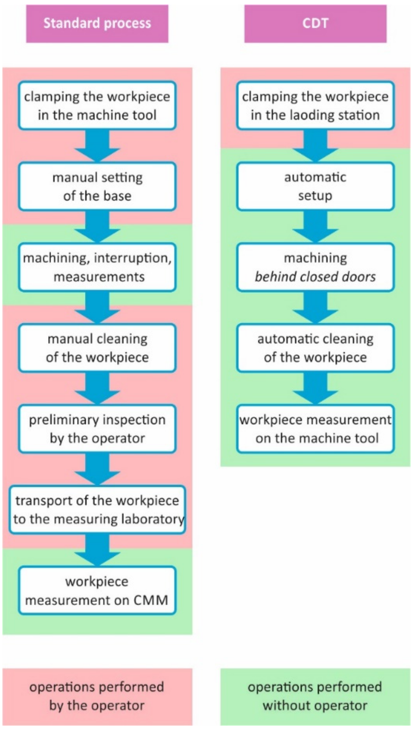
More details on the use of CDT in the ADT casing production process are provided in [
15], where a process executed in a standard manner and a CDT-based process are compared (
Figure 1). That paper points out that some of the most difficult operations to automatize are related to ADT dimensional and shape-related inspection. This happens for at least two reasons. The first is the necessity to ensure adequate accuracy of a CNC machine, which should be used not only as a machine center but also as a measuring device used for quality control during manufacturing. This issue was analyzed and solved by the authors of [
15]. The second reason covers variable conditions during measurements on a CNC machine with respect to measurements carried out using CMM. This variation is due to the different clamping conditions of the part on the CNC machine and on the CMM. Process requirements often impose the need to measure products in a measuring laboratory in an unclamped state (free support) approach, which is not used in practice in machining stations. A change in the clamping condition affects the release of stresses, and this causes the workpiece to deform. Thus, the measurement results of dimensional and shape-related characteristics on a CNC machine and on a CMM differ significantly. The differences are particularly distinct when machining thin-wall components [
16,
17,
18,
19], and these are the components used in the aviation industry in most instances.
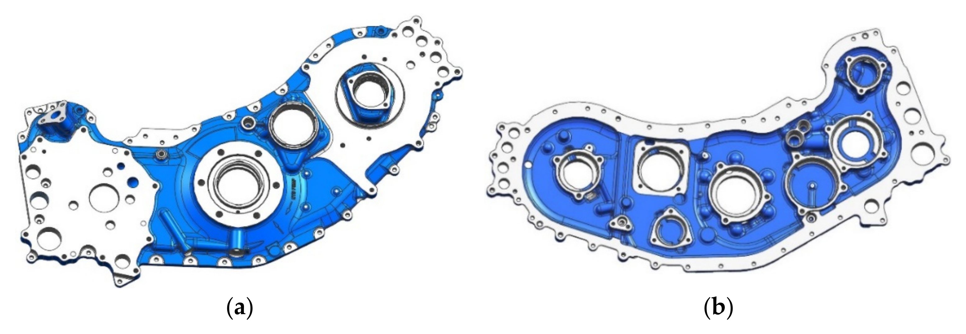
One of the thin-wall components is the ADT casing cover (
Figure 2), the selected dimensional characteristics of which are the subject of research presented in this article. The aim of the study was to develop a method of generation of measurement reports based only on data collected using measuring probes on a CNC machine during and after machining so that it would be possible to eliminate the need to use a CMM. This obviously raises a requirement for CNC machine measurement reports to be concurrent with reports which would be obtained using a CMM. The research presented in the paper is a continuation of previous papers of the authors in which an issue of using a CNC machine to measure workpieces during rough machining was presented [
2]. In the mentioned paper, the number of required measurements on a CMM was significantly reduced owing to the use of an adaptive neuro-fuzzy inference system (ANFIS). The inputs for a trained ANFIS were the data obtained from a CNC machine and one measured value from a CMM, and the output was such a dimensional characteristic as any data collected using a CMM. The greatest contribution of this paper is showing the possibility of completely eliminating the need to use CMMs to control the quality of the ADT casings, which leads to the possibility of implementing CDT in the production of aircraft gearbox casings according to the diagram presented in
Figure 1. Measurement data obtained on the CMM were used at the stage of ANFIS training only as training references for system outputs and the method developed.
The remaining part of the article is organized as follows:
Section 2 includes a description of the measurement inspection of ADT casing covers.
Section 3 describes experimental tests, and
Section 4 includes measurement data analysis and a description of the use of ANFIS in the dimensional inspection process.
Section 5 contains a summary of the main test results.
2. Description of the Issue
An important challenge in the production process is the measurement of dimensional and shape-related characteristics of casing covers during finishing machining on a CNC machine and the generation of a measurement report to ensure that it is equivalent to a CMM measurement report. However, a number of factors stand in the way of such a task, which greatly complicate the mathematical and physical description of the relationship between the state of a body cover clamped on a CNC machining machine and a CMM. Among the many, there are at least three primary factors:
According to the quality requirements, the ADT casing cover should be finally inspected after the finishing machining. On a CNC machine, however, measurements of the selected characteristics may be collected when surfaces and holes are finishing machined on one side of the cover only (on the side of bearing seats). However, on the opposite side of the body cover, there is still an allowance of 0.5–0.7 mm left after roughing operations. The allowance is removed in the next operation, while performing the sequence of operations in reverse order is impossible due to the nature of the body cover design. The existing conditions during the machining process result in not all characteristics being specified for a finished product—some are specified between individual machining operations.
The effect of stress released as a result of unclamping and machining of the other side of the casing covers leads to the fact that the shape of the casing during the measurement on a CNC machine differs from the condition during the final measurement on a CMM.
The body is measured on the CMM in the plant’s measuring laboratory at a stable temperature of 20 °C and a relative humidity of 45%, after keeping the body in the laboratory room for about 5 h. Such measuring conditions are in practice impossible to achieve when measuring on a CNC machine In a machining station, the casing is set in a wet environment resulting from the use of coolants, and the ambient temperature is stable and repeatable but differs from the required 20 °C.
For the above reasons, the development of a reliable measurement report based only on the data collected on a CNC machine is not possible. At the same time, CDT requires full automation of the production process, including quality control. That is why the results of measurements obtained on a CNC machine should be properly converted, according to specific principles, so that they are comparable with the results of measurements obtained in the measurement laboratory. Due to complex relationships, the above-mentioned principles may be specified using methods based on data analysis, and not on an analytical description of physical phenomena. Therefore it was decided to use ANFIS as the system to process input data from a CNC machine to output data as equivalent to measurements carried out on a CMM.
ANFIS combines the properties of an artificial neural network (ANN) and a fuzzy system. The main advantages of the ANN include [
20]: the ability to learn nonlinear mappings from a dataset, the properties of generalizing the information contained in the data, and robustness to errors and data noise. One of the main disadvantages of the ANN is that it is a so-called black box, which means that the relationships between input data and output data cannot be represented in the form of clear principles, and another disadvantage is that the ANN parameters are not interpreted in connection with the subject being solved. A feature of the fuzzy system [
21] is a clear representation of knowledge in the form of inference rules and the possibility to operate on the basis of not only figures, but also linguistic data; thus, it is imprecise. It was shown in [
22,
23,
24] that the fuzzy system may be converted into an ANN structure by creating an ANFIS combining the assets of both structures. This allows the possibility of learning nonlinear mappings based on a dataset and obtaining a base of inference rules that are a clear representation of knowledge. In the context of aircraft production, which is low-volume in nature, the ANFIS generalization capability is of particular importance since the input–output relationship model may be built on the basis of a relatively small training dataset.
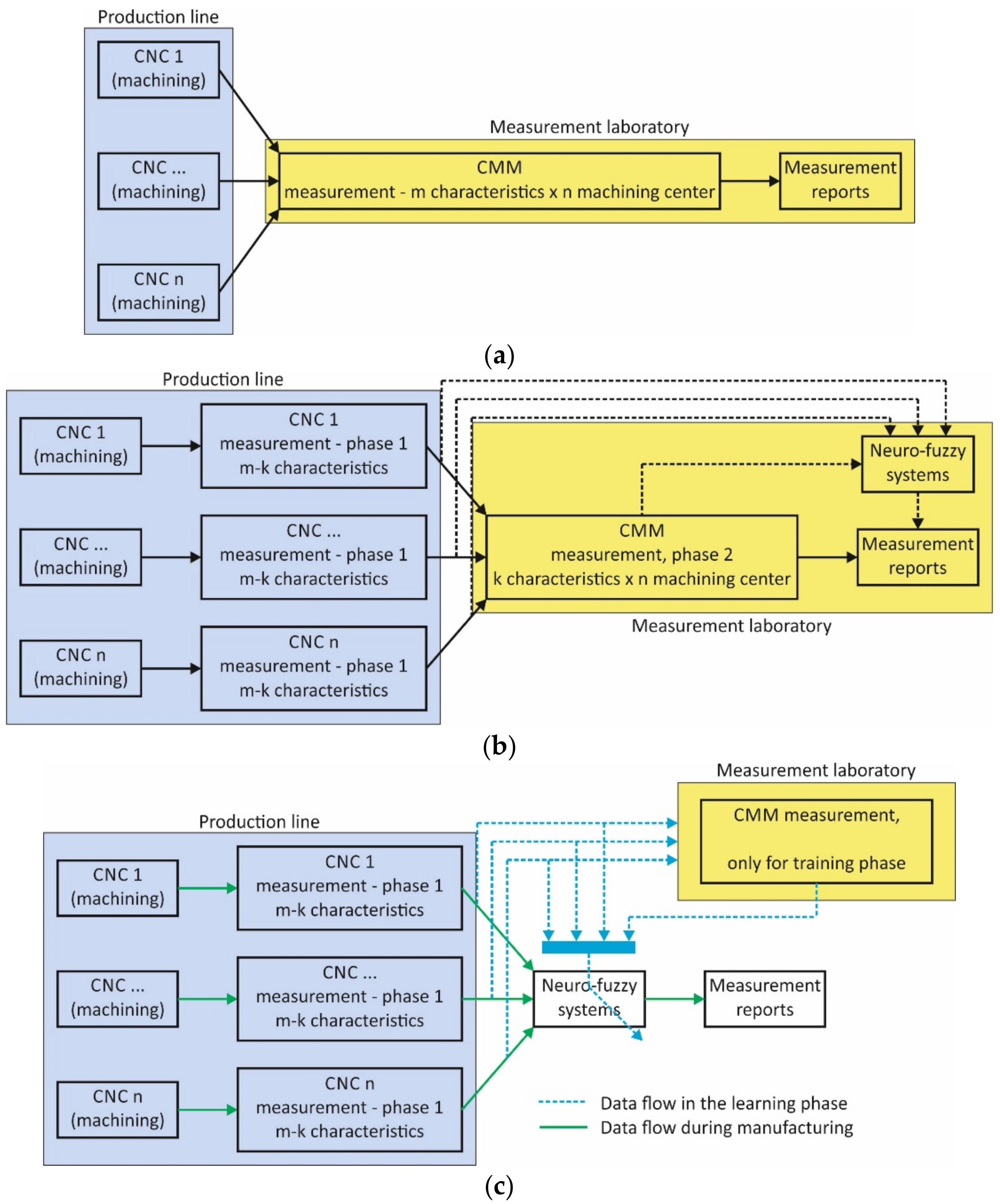
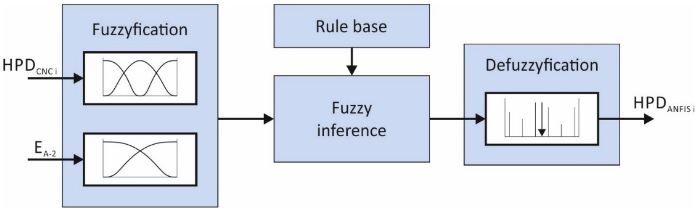
In
Figure 3, three options for a quality control system are presented. Whereas the second and third options are ANFIS-based, the first option (
Figure 3a), which can be called conventional, consists of inspecting the products in a measurement laboratory. In the second option (
Figure 3b), described in paper [
2], a neuro-fuzzy model was used to support the generation of measurement reports. The essential feature of this solution is the utilization of the trained ANFIS model, which is based on k measurements on a CMM and m-k measurements on a CNC machine which is capable of generating outputs that are individual values of dimensions of the ADT casing cover. The advantage of this solution is that instead of m measurements only k measurements are carried out on a CMM. This solution is more affordable, and the k/m ratio is lower. It is an intermediate solution to reach the goal of implementation of CDT on a production line. The third option (
Figure 3c) consists in the utilization of the trained ANFIS model, which on the basis of measurements on a CMM only is capable of generating outputs that are individual values of dimensions of the ADT casing cover. CMM data is necessary at the system training stage only. Data flow at the training stages is marked in blue, whereas data flow at the system operation stage is marked in green.
Details of the solution presented in
Figure 3c are the subject of this article and are described in the following sections.
3. Experimental Tests
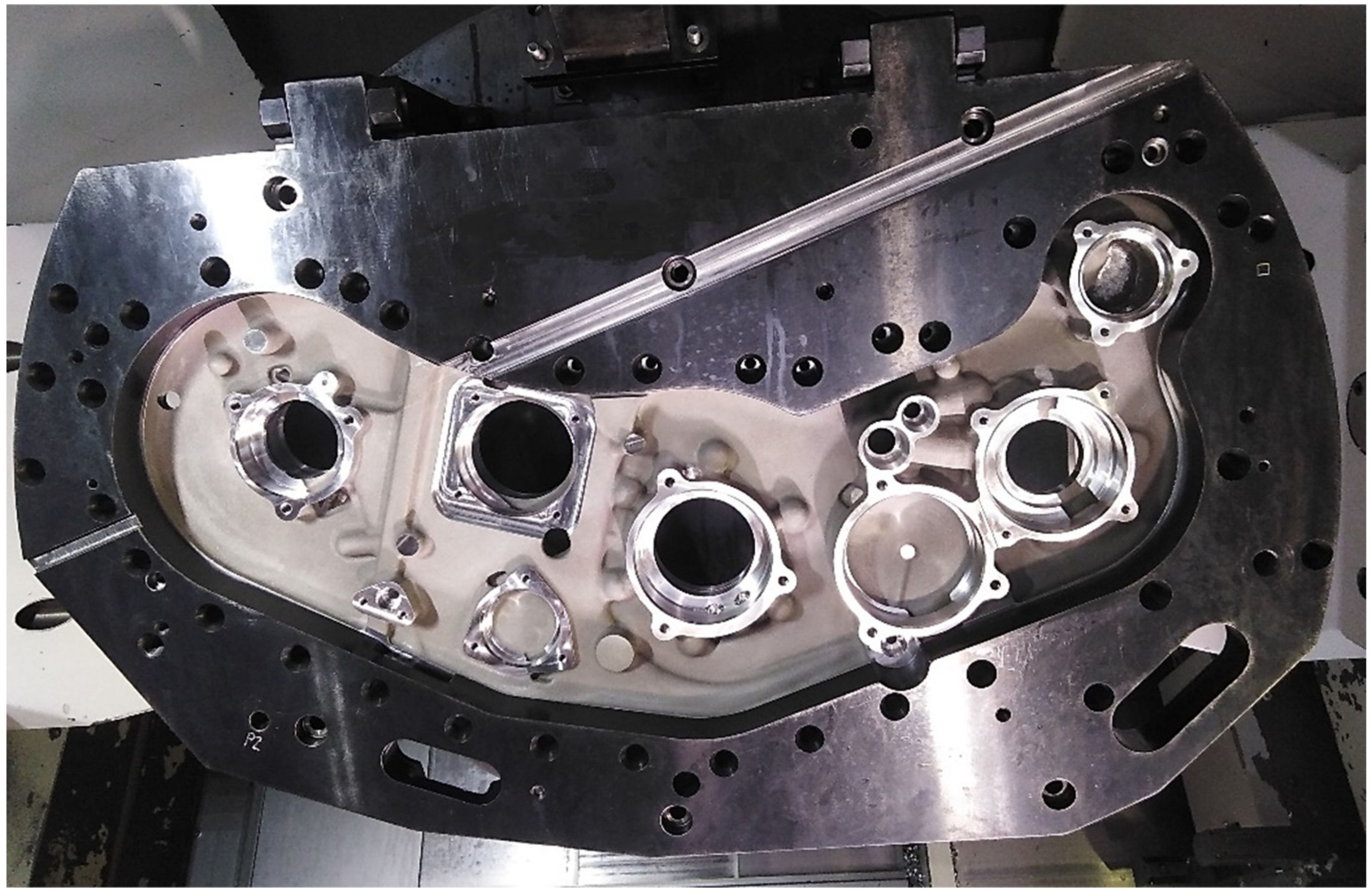
In order to train the ANFIS, it is necessary to acquire data from the actual ADT body cover manufacturing process (
Figure 4). The technological operation considered to give the final shape is a machining operation. Under this operation, e.g., gearbox kinematic chain bearing seats are machined. The main cover features are as follows:
The type and condition of the material used for the case are detailed in specification AMS4215;
The rough product is a pre-machined sand and die casting;
Residual casting stress occurs in the rough product;
The size of the removed material allowance is up to 0.5–0.7 mm;
Minimum thickness after machining is 4 mm;
Positional tolerance of bearing seats and base holes is 0.076 mm;
Bearing seat diameter tolerance is 0.050 mm;
Roughness of bearing seats is Ra = 1.6 μm.
Prior to detail machining, the accuracy of the CNC machine was verified by performing the test described in [
25]. The machine accuracy assessment was also performed based on the standards ISO 230-2:2014 and ISO 230-6:2002. ISO 230-2:2014 specifies methods for testing and evaluating the accuracy and repeatability of positioning of numerically controlled machine tool axes by direct measurement of individual axes on the machine. These methods apply equally to linear and rotary axes. ISO 230-6:2002 specifies diagonal displacement tests which allow the estimation of the volumetric performance of a CNC machine. It consisted in making a test part and checking the accuracy of the part in a different machine such as a CMM. All geometrical errors were within the required tolerances adopted for a new machine. For measurements on the CNC machine, a Renishaw RMP600 probe (manufactured by Renishaw plc, Wotton-under-Edge, UK) equipped on the machine tool was used. Before machining, the measuring probe was calibrated using a calibration ring and Renishaw calibration procedure. Sufficient accuracy and repeatability of such a measuring system were demonstrated in [
15,
19]. The main features of the RMP600 probe are as follows: unidirectional repeatability is 0.25 µm 2σ; 3D lobing in X, Y, and Z is ±1.00 µm; ultra-low stylus trigger force in XY is 0.2 N; the sensitive element is a strain gauge; styli made of high modulus carbon fiber; and communication by radio transmission with frequency hopping spread spectrum technology (FHSS).
Then machining of 97 covers was carried out with simultaneous measurement of selected dimensional characteristics. The process was performed on a 5-axis Okuma MU6300V machining center (manufactured by Okuma Corporation, Ōguchi, Japan) in an automatic cycle, with no operator interference in machining parameters, machine system positioning, clamping, or measurement method.
The cutting tools used for finish boring of bearing seats are precision adjustable boring tools of type 564034 (Allied Machine and Engineering, Dover, OH, USA) with insert holder 210052 and cutting insert TCMT9T306. Carbide cutting inserts with brazed PCD diamond blades were used. Cutting insert working time was assumed to be 1000 h. No wear of the cutting insert or change in the diameters of the bored seats was observed during the machining of the bearing seats in the covers. The cutting parameters for the boring bars were selected experimentally and are as follows: cutting speed Vc = 12 m/min, feed rate fr = 0.02 mm/min, material allowance ap = 0.25 mm, cutting power P = 14 W.
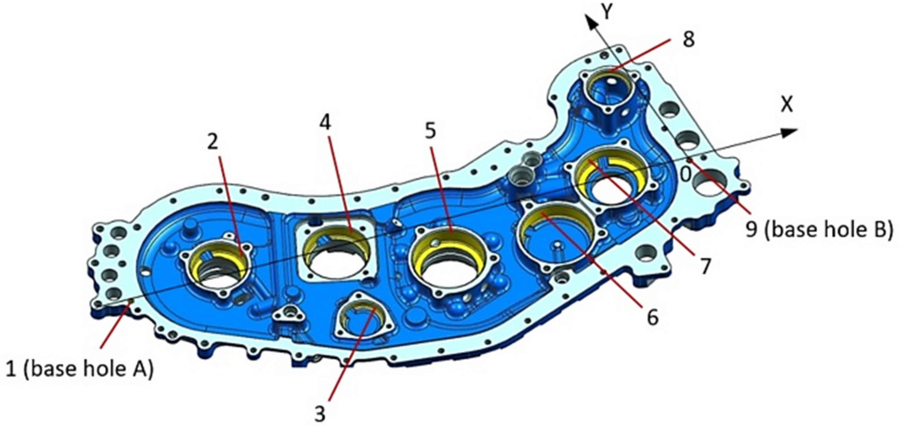
The aim of the measurements was to obtain experimental data required to build training and inspection (validation and testing) sets for ANFIS. In
Figure 5, bearing sets (from 2 to 8) with their position measured for both the CMM and the CNC machine are marked. Two base holes are also indicated—the center of hole B is simultaneously the origin of the reference system for both the CMM and the CNC machine. Base hole A is used to properly align the cover—the x-axis of the reference system goes through its center.
The distance between axes of the base holes A and B is 700 mm. The distance from the axis of the base hole B to the axis of seat 2 is 587 mm, and the distance from the axis of hole B to the axis of seat 6 is 197 mm. The true position tolerance of hole axes from 1 to 9 is 0.076 mm, and bearing seat diameter tolerance is 0.050 mm. The true position tolerance provides information about the maximum allowable deviation of a feature (e.g., hole, slot) from its true position. By true position, we mean the ideal position of the feature according to design.
Upon completion of the operation, the machine accuracy was again verified, according to ISO 230-2:2014 and ISO 230-6:2002 and the test described in [
25]. No significant change in the values of geometrical errors of the machine tool was registered. All values were once more within the required tolerances adopted for a new machine, such as geometric accuracy of machines operating under no-load or quasi-static conditions, determination of accuracy, and repeatability of positioning of numerically controlled axes.
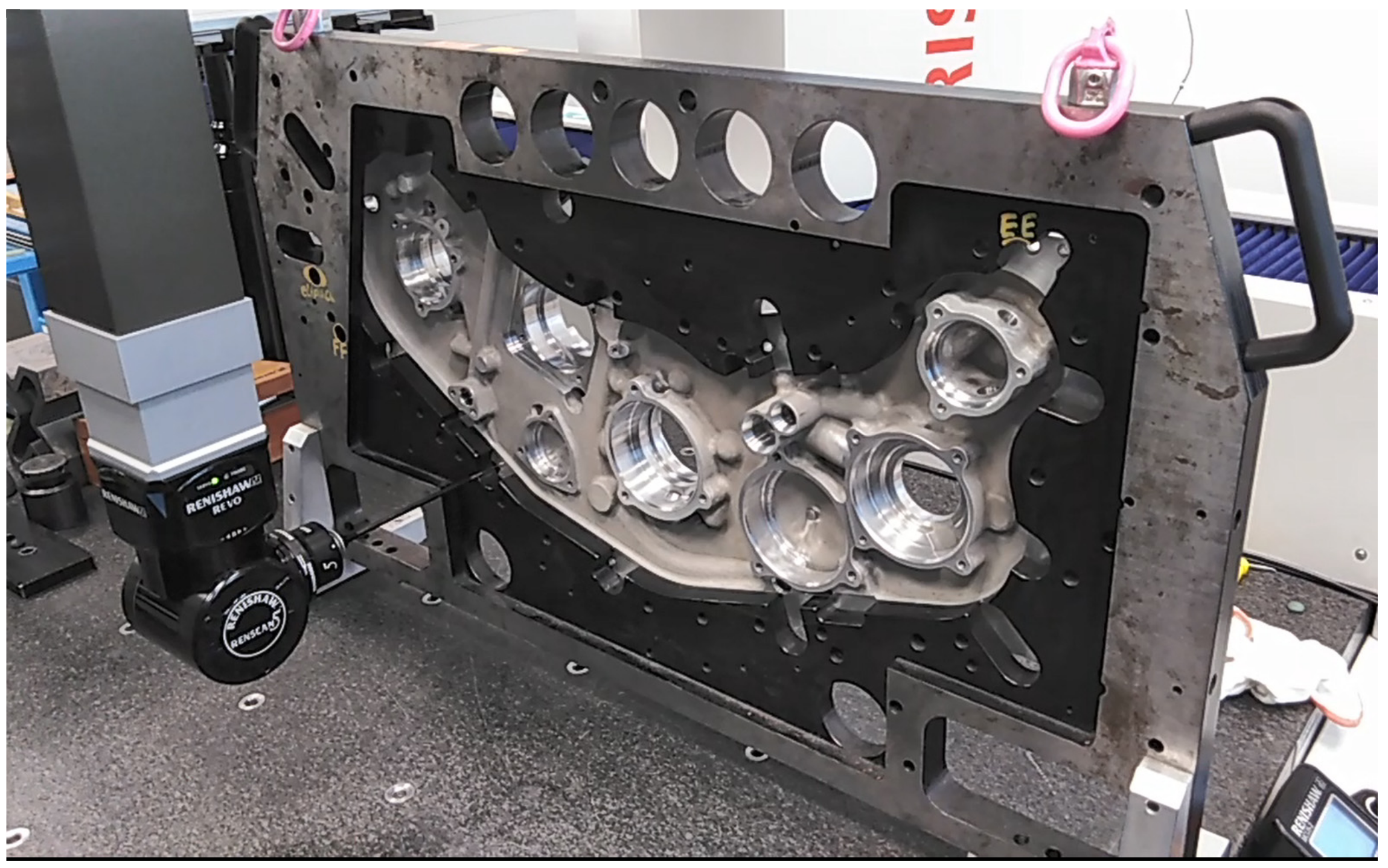
Then reference measurements of the covers were carried out in the measurement laboratory according to a standard measurement procedure approved in the production technology. These measurements constitute a point of reference for a new developed quality control procedure. For measurement, a Mitutoyo coordinate measuring machine (manufactured by Mitutoyo Corporation, Kawasaki, Japan) with a Revo2 rotary head and Modus 1.7 measuring software (developed by Renishaw plc, Wotton-under-Edge, UK) was used (
Figure 6).
The accuracy of the CMM was evaluated based on the standard ISO 10360-2:2009. ISO 10360-2:2009 specifies the acceptance tests for verifying the performance of a coordinate measuring machine (CMM) used for measuring linear dimensions as stated by the manufacturer. It also specifies the reverification tests that enable the user to periodically reverify the performance of the CMM. The acceptance and reverification tests given in ISO 10360-2:2009 are applicable to Cartesian CMMs using contacting probing systems of any type operating in the discrete-point probing mode. According to the mentioned standard, the uncertainty of CMM measurement is 5 µm.
On the basis of measurement results, hole position deviations (HPDs) for bearing seats with respect to nominal values were determined. Deviations determined on the basis of measurements on the CMM were designated as HPD
CMMi, whereas deviations determined on the basis of measurements on the CNC machine were designated as HPD
CNCi, where I = 2, 3, …, 8 indicates the number of a bearing seat. Hole position deviations for base hole 1 were determined in a similar manner. Afterward, the correlation of CMM data with CNC machine data was examined by determining the Pearson correlation coefficient. The values of the correlation coefficient are presented in
Table 1. The axis of hole 9 presented in
Figure 5 is the origin of a coordinate system for measurements on the CNC machine and on the CMM. For this reason, it was not included in
Table 1.
The obtained values of the Pearson coefficient indicate that the correlations are negligible to moderate in size [
26].
4. Case Study
4.1. Measurement Data Analysis
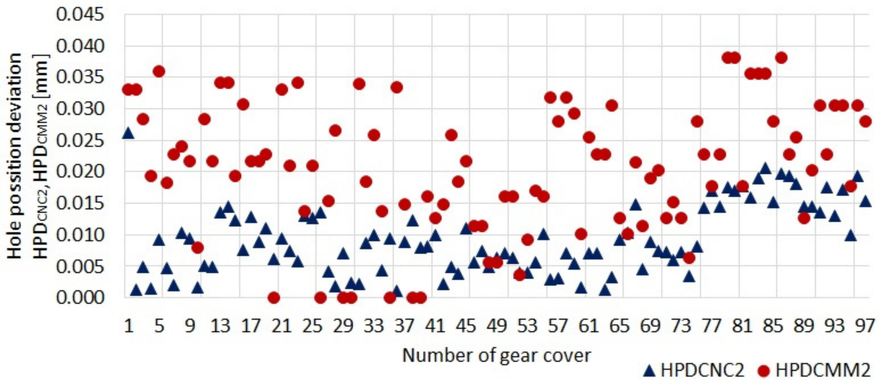
In the following part of this article, measurement data and analyses for a selected bearing seat, namely bearing 2, are presented. The correlation between results of CNC measurements and CMM measurements expressed as the Pearson coefficient for this seat is 0.09 and is considered low. It means that the measurement results obtained from the CNC machine do not reflect the measurement results obtained from the CMM. It is thus one of the most difficult cases in the examined subject and stems from the fact that the bearing seat 2 is the farthest seat from base hole B. As a result, when the cover is unclamped after machining, this seat is subject to the greatest displacement with respect to the reference system.
The results of measurements carried out on the CNC machine and on the CMM for 97 covers are presented in
Figure 7, whereas instead of coordinate values for hole axes in the reference system, deviations from nominal values are given. Owing to this fact, the differences in the results are more visible.
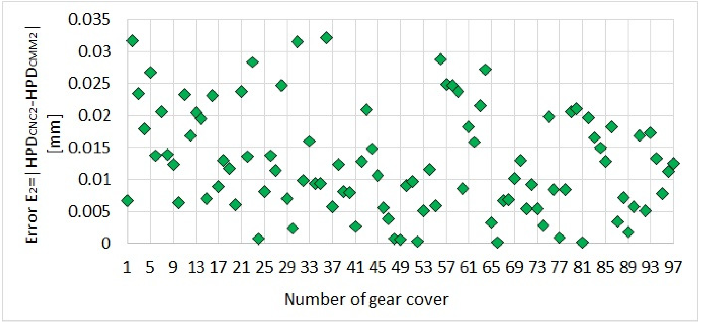
For the data given in diagram 7, measurement errors were calculated on the CNC machine, understood as differences between deviation values:
Values of these errors are presented in
Figure 8.
For the considered bearing seat 2, the average value of measurement error is E2AVE = 0.013 mm, whereas the maximum value of measurement error is E2MAX = 0.032 mm. On the basis of the above analysis, it may be concluded that the measurement results obtained from the CNC machine have low reliability. Error E2, being the difference between CNC and CMM measurements, takes excessively high values, close to the half of positional tolerance for bearing seat 2.
As a result, an approach was suggested dealing with the consideration of system information, in addition to error HPD
CNC2, that will allow for association of the results of measurements carried out on the CMM and on the CNC machine. In the previous paper of the authors [
2], it was demonstrated that the difference between the measurements carried out on the CMM and on the CNC machine is correlated with the cover basing surface curvature. In the above paper, curvature was determined on the CMM and constituted one of the ANFIS inputs. Due to the fact that in this paper elimination of CMM measurements is assumed, attention was paid to finding another parameter that would provide ANFIS with information on stress released during machining which, in effect, after unclamping the cover, results in the lack of surface flatness.
The specific nature of the cover is such that the machined bearing seats are on free surfaces; i.e., the clamping points of the cover during machining are at a considerable distance from the machined seats, which change their position relative to the other parts of the cover due to the release of stresses.
Error HPDCNC2 determined with respect to the nominal value contains no information on local cover deformations. Hence, it was suggested that an additional system input was a variable describing the relationship between measurement results of two selected elements. A reference of measurement results not to a global system, but to another measured element, will provide information on cover deformations, and indirectly on the released stress. That said, such an input to ANFIS will provide information about the relationship between CMM and CNC measurement results.
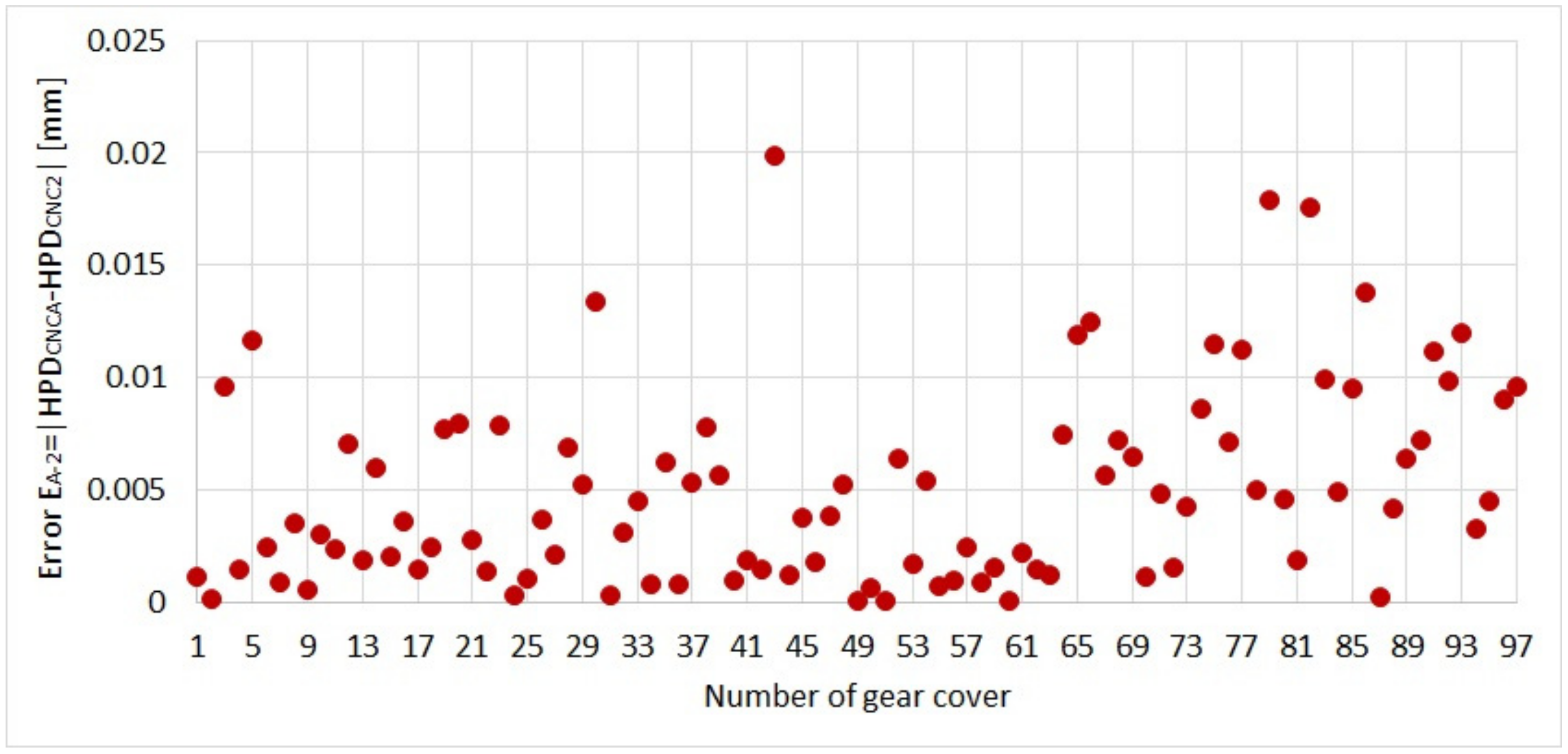
Due to the specification of the cover, this additional input to ANFIS is defined as:
where HPD
CNCA is a base hole A position deviation from the nominal value determined on the basis of the measurements carried out on the CNC machine, and HPD
CNC2 is a bearing seat 2 positional deviation from the nominal value also determined on the basis of the measurements carried out on the CNC machine. The values E
A−2 for 97 covers are presented in
Figure 9.
Summing up the above considerations, it should be stated that the results of measurements carried out on the CNC machine themselves cannot be used to generate an appropriate measurement report. To overcome this difficulty, an application of ANFIS is provided in which inputs will include two values: HPDCNC2, a deviation expressed with respect to nominal values, and EA−2, a deviation expressed relatively.
4.2. ANFIS Application—Case of Bearing Seat 2
The data shown in
Figure 7 (only HPD
CNC2) and
Figure 9 were used to teach and evaluate the ANFIS learning process. A set of training data containing 72 data groups and a set of testing data containing 25 data groups used to check the quality of the training process were prepared. The test set was prepared so that every fourth result was selected from all the results and assigned to the test group and the remaining results were assigned to the training group.
A diagram of ANFIS and a mathematical description of data processing and the training process can be found in numerous references, e.g., [
27,
28]. That is why this paper is limited to important features and parameters of ANFIS that were adopted after numerous tests. A general ANFIS structure is presented in
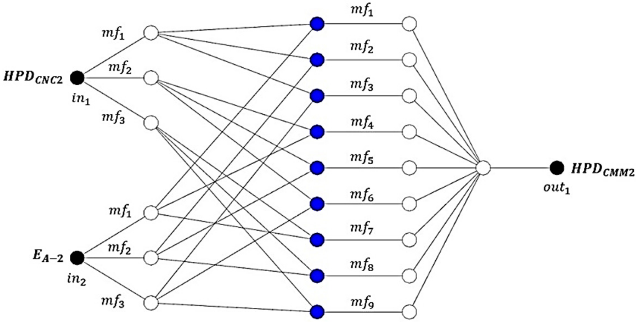
Figure 10.
Membership functions of fuzzy sets were assumed in the form of Gaussian curves—three sets per input variable. For an output variable, the so-called singletons, i.e., fixed values, were assumed in the quantity of 9. Sharpening was carried out on a weighted average basis. The desired output values from ANFIS were deviations specified on the basis of the results of measurements carried out on the CMM (HPD
CMM2 presented in
Figure 7). The following rule base was created:
in which parameters of premises (widths and positions of fuzzy set centers) and conclusions (singleton values) were trained. A network structure and flow chart are presented in
Figure 11.
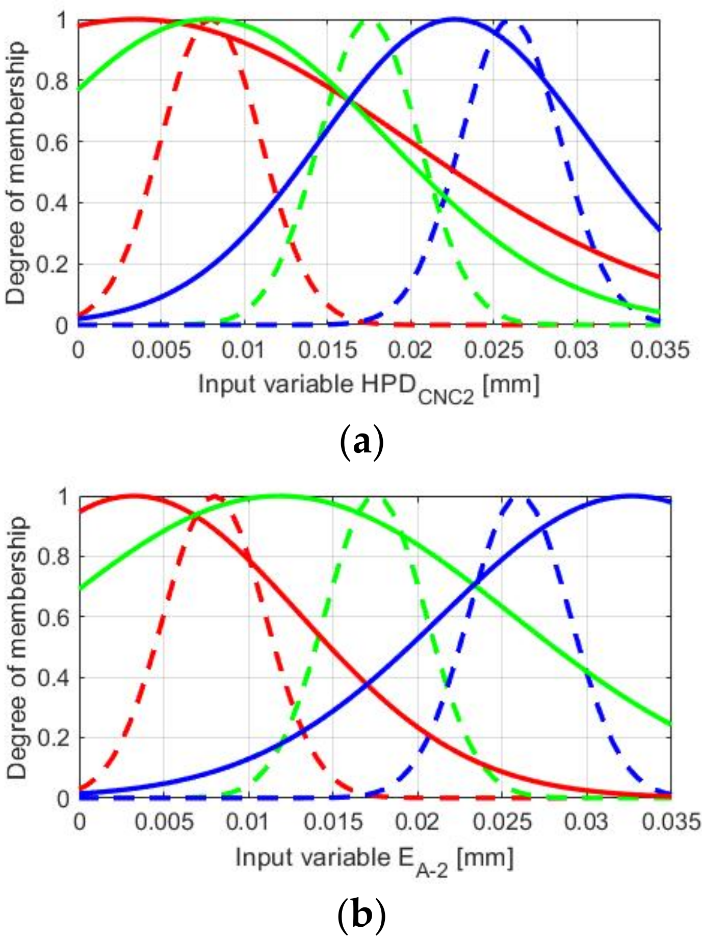
Membership functions of fuzzy sets for input variables before and after the training process are presented in
Figure 12, whereas the values of output singletons are given in
Table 2.
Figure 13 shows the surface of the neuro-fuzzy model after the learning process.
After the training process, data from the test set were applied to ANFIS inputs, and the average error for ANFIS
maximum error
and error for each pattern from the test set
were determined. The obtained values of average error and maximum are δ
AVE = 0.008 mm and δ
MAX = 0.014 mm, respectively. On the other hand, the values of errors δ
2 for the data from the test set are presented in
Figure 14, with error E
2 based on the difference between CMM and CNC measurements.
The obtained values of errors δ2AVE and δ2MAX are significantly lower than the original errors E2AVE = 0.013 mm and E2MAX = 0.032 mm. Error δ2AVE constitutes 62% of error E2AVE, whereas error δ2MAX constitutes 44% of error E2MAX.
4.3. ANFIS Application—Case of Bearing Seat 6
To confirm the effectiveness of the method, an analogous procedure was performed for bearing seat 6. The correlation value of measurements HPD
CMM6 and HPD
CNC6 is 0.3 (
Table 1), which constitutes a low correlation, and the values of average error and maximum error are both E
6AVE = 0.015 mm, whereas the maximum value of measurement error is E
6MAX = 0.034 mm. Inputs to ANFIS included HPD
CNC6 and, as in the previous model, a deviation expressed relatively, E
A−2. The structure of training and testing data, the structure of ANFIS, and the rule base were adopted as in the previous case analyzed.
The obtained values of average error and maximum are δ
6AVE = 0.007 mm and δ
6MAX = 0.014 mm, respectively. On the other hand, the values of errors δ
6 for the data from the test set are presented in
Figure 15, with error E
6 based on the difference between CMM and CNC measurements.
The obtained values of average error and maximum error are again lower than the values of original errors specified on the basis of measurements carried out on the CNC machine. Error δ6AVE constitutes 44% of error E6AVE, whereas error δ6MAX constitutes 45% of error E6MAX.
5. Conclusions
In this paper, an issue concerning the execution of measurements on a CNC machine during the production of aircraft gearbox covers is presented. It was solved by using a method belonging to the spectrum of artificial intelligence methods.
Owing to the input use of variable EA−2 containing information on cover deformations, it was possible to eliminate the need to carry out measurements of the produced elements in the measurement laboratory on the CMM. This is the main achievement of the paper and at the same time the fulfillment of the set aim. Simultaneously, it becomes possible to apply CDT for the production of aircraft gearbox casings.
The main findings of the studies presented are as follows:
Errors between measurements carried out on the CMM and the CNC are up to 0.032 mm for bearing seat 2 and up to 0.034 mm for bearing seat 6, and when ANFIS is used, they are up to 0.014 mm for bearing seats 2 and 6;
The average errors between measurements carried out on the CMM and the CNC are 0.013 mm for bearing seat 2 and 0.015 mm for bearing seat 6, and when ANFIS is used, they are 0.008 mm for bearing seat 2 and 0.007 mm for bearing seat 6;
After using ANFIS, the average errors for bearing seat 2 account for 62% of the original average measurement error, and the average errors for bearing seat 6 account for 44% of the original average measurement error.
A further stage of the work will consist in the implementation of the system for aircraft production which at the current stage may operate in parallel to the existing quality control system. This solution will allow for verification of system operation over a longer period of time, continuous extension of the set of data obtained from the production process, and additional ANFIS training.


