Article

Finite Element Analysis for Pre-Clinical Testing of Custom-Made Knee Implants for Complex Reconstruction Surgery

1
Research & Development Department, Aesculap AG, 78532 Tuttlingen, Germany
2
Research & Development Department, AQ Solutions GmbH, 50354 Hürth, Germany
3
Department of Orthopaedic and Trauma Surgery, Musculoskeletal University Center Munich (MUM), Campus Grosshadern, Ludwig Maximilians University Munich, 81377 Munich, Germany
*
Author to whom correspondence should be addressed.
Submission received: 30 March 2022 / Revised: 27 April 2022 / Accepted: 2 May 2022 / Published: 9 May 2022
(This article belongs to the Special Issue Recent Advance in Finite Elements and Biomechanics)

Abstract

:

Featured Application

The results of this work could be applied to the pre-clinical testing of custom-made knee implants.

Abstract

In severe cases of total knee arthroplasty, where off-the-shelf implants are not suitable or available anymore (i.e., in cases with extended bone defects or periprosthetic fractures), custom-made knee implants represent one of the few remaining treatment options. Design verification and validation of such custom-made implants is very challenging. The aim of this study is to support surgeons and engineers in their decision on whether a developed design is suitable for the specific case. A novel method for the pre-clinical testing of custom-made knee implants is suggested, which relies on the biomechanical test and finite element analysis (FEA) of a comparable reference implant. The method comprises six steps: (1) identification of the main potential failure mechanism and its corresponding FEA quantity of interest, (2) reproduction of the biomechanical test of the reference implant via FEA, (3) identification of the maximum value of the corresponding FEA quantity of interest at the required load level, (4) definition of this value as the acceptance criterion for the FEA of the custom-made implant, (5) reproduction of the biomechanical test with the custom-made implant via FEA, (6) conclusion, whether the acceptance criterion is fulfilled or not. Two exemplary cases of custom-made knee implants were evaluated with this method. The FEA acceptance criterion derived from the reference implants was fulfilled in both custom-made implants. Subsequent biomechanical tests verified the FEA results. The suggested method allows a quantitative evaluation of the biomechanical properties of a custom-made knee implant without performing a biomechanical test with it. This represents an important contribution in the pre-clinical testing of custom-made implants in order to achieve a sustainable treatment of complex revision total knee arthroplasty patients in a timely manner.

Graphical Abstract

1. Introduction

Recent advances in three-dimensional imaging and additive manufacturing allow novel personalized clinical treatments [1]. In orthopedics, such techniques were commonly used to design patient-specific instruments, which are specific to the patient’s anatomy to achieve an accurate implant alignment [2,3]. Further, the use of personalized knee implants in total knee arthroplasty (TKA) has become increasingly popular in recent years [4]. Although personalized knee implants accurately restore the mechanical axis of the patient’s anatomy through an improved implant design and implant fit [5], clinically important improvements compared to conventional off-the-shelf implants could not be shown for “uncomplicated” primary TKA [6].
In more “complicated” TKAs, such as trauma injuries or revision cases, which are often associated with severe bone loss, personalized knee implants provide a substantial benefit for the patients [7,8]. In these cases, when off-the-shelf implants are not suitable or available anymore, personalized knee implants could serve as one of the few remaining options to restore the joint function or even prevent limb amputation [9]. The costs for a custom-made knee implant are higher compared to off-the-shelf implants and highly depend on the complexity of the implant and whether additional instruments are required. It was reported that the costs vary between EUR 4321.53 and EUR 19,900.82 [9]. The overall healthcare costs in terms of projected lifetime healthcare cost has been reported to be three times lower comparing reconstruction with amputation of a limb-threating injury (USD 163,282 compared to USD 509,275) [10].
Personalized knee implants are distinguished in patient-matched implants and custom-made implants [11,12]. Patient-matched implants are adjusted to the patient’s anatomy within a specific design envelope and are designed and produced under the responsibility of the implant manufacturer. Custom-made implants are intended to address the specific condition of one single patient with specific design characteristics in a single-unit production [12,13]. The responsible surgeon and the corresponding engineer work in close collaboration, whereby, in very simplified terms, the surgeon is responsible for the medical evaluation and the engineer for its proper and careful realization [11,14]. The manufacturing of a custom-made implant is based on established and validated processes under a quality management system [15,16,17].
Due to the inherent unique design characteristic, the design process is one of the most critical parts during the workflow of a custom-made implant [15]. In particular, the validation and verification for critical mechanical endurance properties is a very challenging task. Pre-clinical biomechanical tests, as routinely performed for off-the-shelf implants, are impractical for a single-unit custom-made implant due to the unique design and, depending on the diagnosis, the limited available supply time. It has been recommended that a custom-made implant should be based on a underlying medical device or reference implant, which allows certain variants or modifications [14,16]. Validation and verification of the intended purpose of the underlying reference implant should be performed and documented in advance. When a specific custom-made implant is requested by a surgeon, it must be proven that the custom-made implant is covered by the underlying medical device [16].
In a few cases, a patient’s diagnosis requires a custom-made implant with a specific design feature, which is not covered by an underlying reference implant. This feature in the custom-made implant needs to be evaluated in advance to the clinical use within the mandatory benefit–risk analysis. Since prolonged supply time often negatively affects the patient’s condition, the shortest possible evaluation time for the benefit–risk analysis is desirable. For mechanical considerations, a finite element analysis (FEA) is beneficial and has been commonly used in the pre-clinical testing of orthopedic devices [18]. Using FEA in pre-clinical testing, it is recommended to define the “question of interest” and the “context of use” [19] at the beginning. Then, the model risk needs to be identified (i.e., the severeness of the consequences caused by incorrect FEA results). Based on this, the model credibility could be obtained (i.e., the usefulness of the model by verification and validation), which includes the evaluation against an adequate comparator. An adequate comparator could be an in vitro study (e.g., biomechanical test) or an in vivo study (e.g., a clinical trial). Only in cases when the model credibility in the defined “context of use” is acceptable, could the “question of interest” be answered by the model.
To predict the mechanical properties of custom-made knee implants using an FEA, the potential failure mechanism and its corresponding quantity of interest need to be identified [20]. Then, an adequate comparator needs to be defined, which could be the corresponding reference implant and its biomechanical results. However, this requires that the custom-made implant is comparable to the reference implant in terms of intended use, design, material, manufacturing and loading, and that the reference implant has been successfully tested according to given standards.
The aim of this study is to provide surgeons and engineers with a method to evaluate the mechanical properties of a custom-made knee implant, in a fast and quantitative way, to support their decision on whether the design is suitable for this specific case. Within this method, the biomechanical test of a reference implant is reproduced by FEA to obtain the value of the crucial quantity of interest at the required load level. The biomechanical test is then also reproduced with the custom-made implant and the obtained value is used as the acceptance criterion. It is assumed that, when the reference implant fulfills the biomechanical acceptance criterion and the custom-made implant is exposed to equal or less mechanical burden, the custom-made implant would fulfill the acceptance criterion. Under the above-described requirements, it is hypothesized that the mechanical performance of a custom-made implant can be evaluated solely by FEA.
The hypothesis was tested in two exemplary custom-made knee implants. In custom-made implant 1, a geometrical modification of the reference implant was evaluated. In custom-made implant 2, the taper junction from a custom-made implant to an off-the-shelf implant was evaluated. For these two examples, biomechanical tests and FEA of the reference implants, as well as the custom-made implants, were performed. The FEAs showed that, in both examples, the custom-made implants were exposed to less mechanical burden compared to the corresponding reference implants. The acceptance criterion for the custom-made implants were fulfilled in both biomechanical tests.

2. Materials and Methods

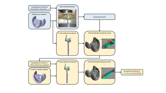
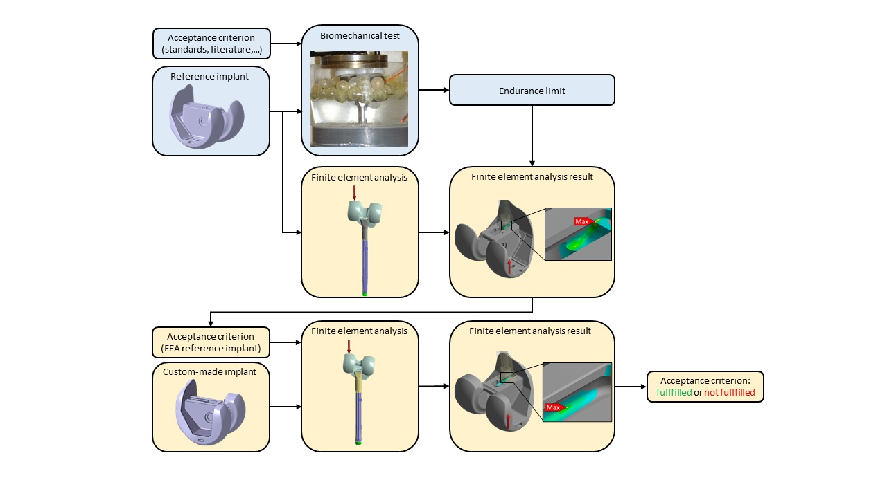
2.1. Pre-Clinical Testing Method for Custom-Made Knee Implants

Pre-clinical biomechanical tests could be summarized in the steps “Input”, “Test”, “Output”, and “Conclusion” (Figure 1). For an off-the-shelf implant, a pre-defined acceptance criterion from specific standards, previous studies, literature and/or specific lab experience (“Input”) could be tested in a dedicated biomechanical test setup (“Test”). The resulting endurance limit (“Output”) defines whether the pre-defined acceptance criterion is fulfilled or not (“Conclusion”) (Figure 1a).
The mechanical burden on a custom-made implant during physiological load could be simulated via FEA. However, since a clinically relevant acceptance criterion cannot be defined in advance, the FEA does not yield to a conclusion (Figure 1b). The suggested method takes advantage of the biomechanical test of the reference implant to define the acceptance criteria for the custom-made implant. The biomechanical test of the reference implant is reproduced in an FEA. The endurance limit obtained by the biomechanical test could then be correlated to the FEA results. The clinically relevant mechanical load could be transferred to FEA and used as the acceptance criterion for the FEA of the custom-made implant. Thereby, the FEA of the custom-made implant yields to a conclusion such that the mechanical endurance properties of a custom-made implant could be assessed without performing a biomechanical test with it (Figure 1c). The method was applied to two exemplary custom-made knee implants.
To replicate a biomechanical test using FEA, the relevant elements from the biomechanical test setup need to be modeled in the FEA test setup (Figure 2). The cyclic loading of a biomechanical test is replicated by a quasistatic load in the FEA. The embedding of the stem in casting resin is modeled by an elastic support. The basis of the test machine is modeled in FEA by a fixed support. Details of the specific biomechanical test method are given in Section 2.3 and details of the FEA in Section 2.4.

2.2. Custom-Made Knee Implants

Two custom-made knee implants were considered in this study (Table 1). Custom-made implant 1 is a geometrically modified version of reference implant 1. Aseptic implant loosening associated with severe bone defects of a 71-year-old male patient with cement and metal ion sensitivity requires a custom-made implant. The interconnection position of the stem at the custom-made implant is in a more anterior position compared to the reference implant. This modification has become necessary due to the severe femoral bone loss in combination with the specific patient anatomy. For such a modification, mechanical fatigue around the interconnection area was identified by a risk-based approach as the main potential mechanical failure mechanism. In the reference implant, this failure mechanism was evaluated in the pre-clinical biomechanical test through a dedicated femur stem fatigue test [21]. In an FEA, the quantity of interest would be tensile stress and complementary van Mises stress, elastic deformation and micromotion.
In custom-made implant 2, the taper junction from an off-the-shelf implant compared to the custom-made implant was evaluated. In this specific case, a 76-year-old female patient showed a recurrent periprosthetic fracture at the tip of the femoral stem after stabilization with a plate. Patient’s diagnosis showed a tibial implant with good osteointegration. The responsible surgeon required a custom-made femur implant which is compatible with the existing tibial implant and which provides a taper junction to an off-the-shelf revision system of another manufacturer. The taper junction is a potential cause of fretting and corrosion, which has been reported as a potential cause of early failure and revision surgery [22]. Therefore, the taper junction is considered as the main potential mechanical failure mechanism. In FEA, the quantity of interest would be micromotion and complementary tensile and van Mises stress.

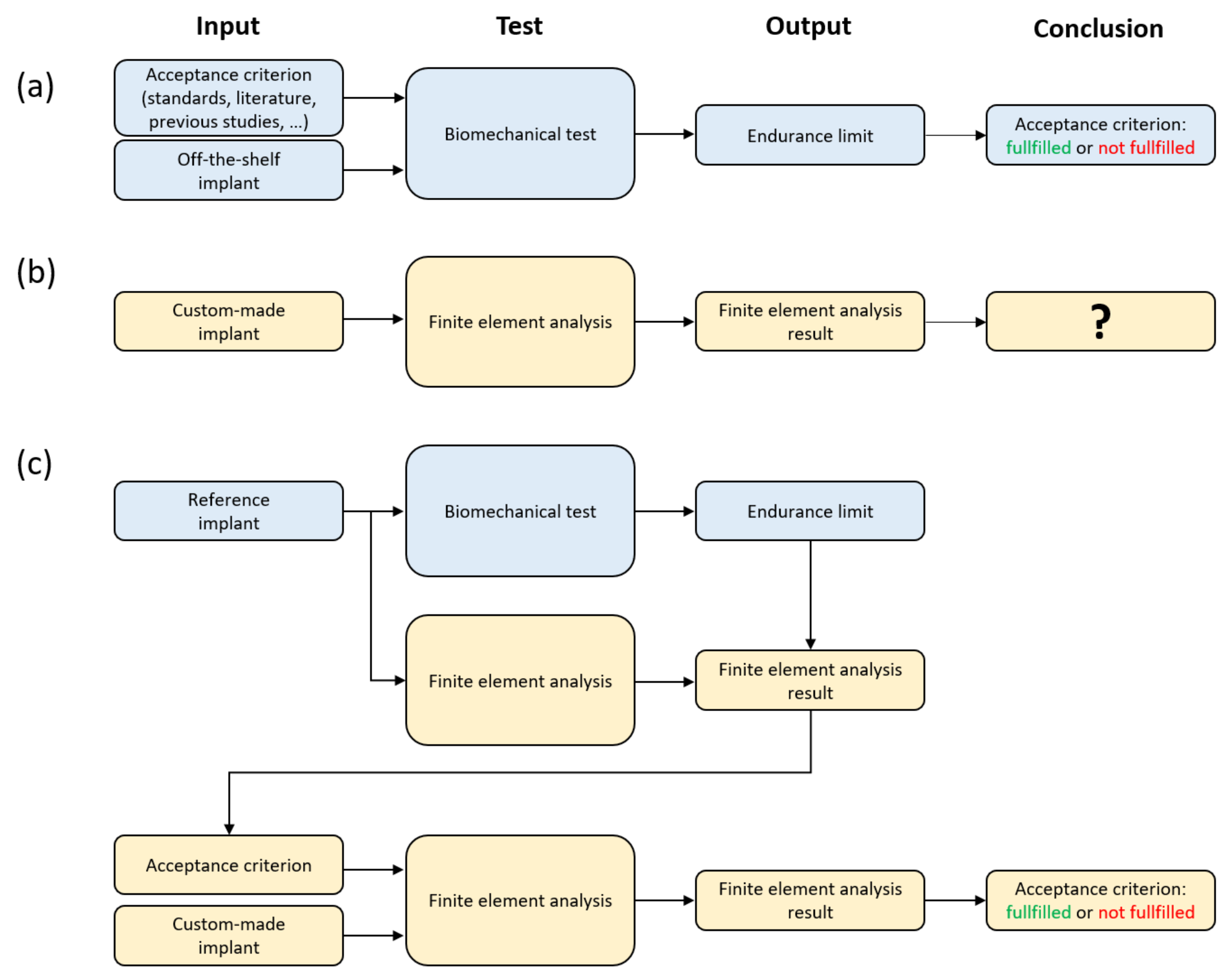
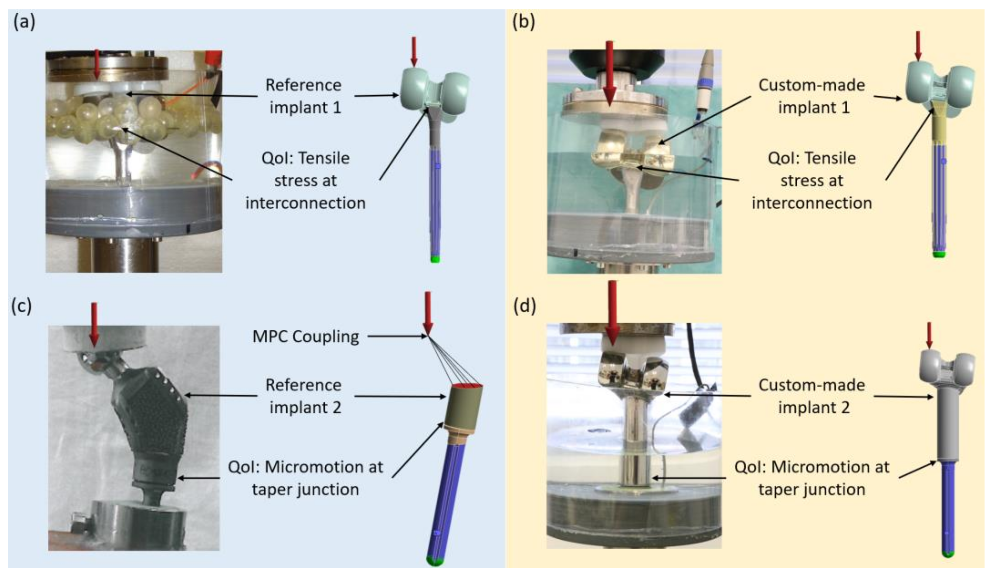
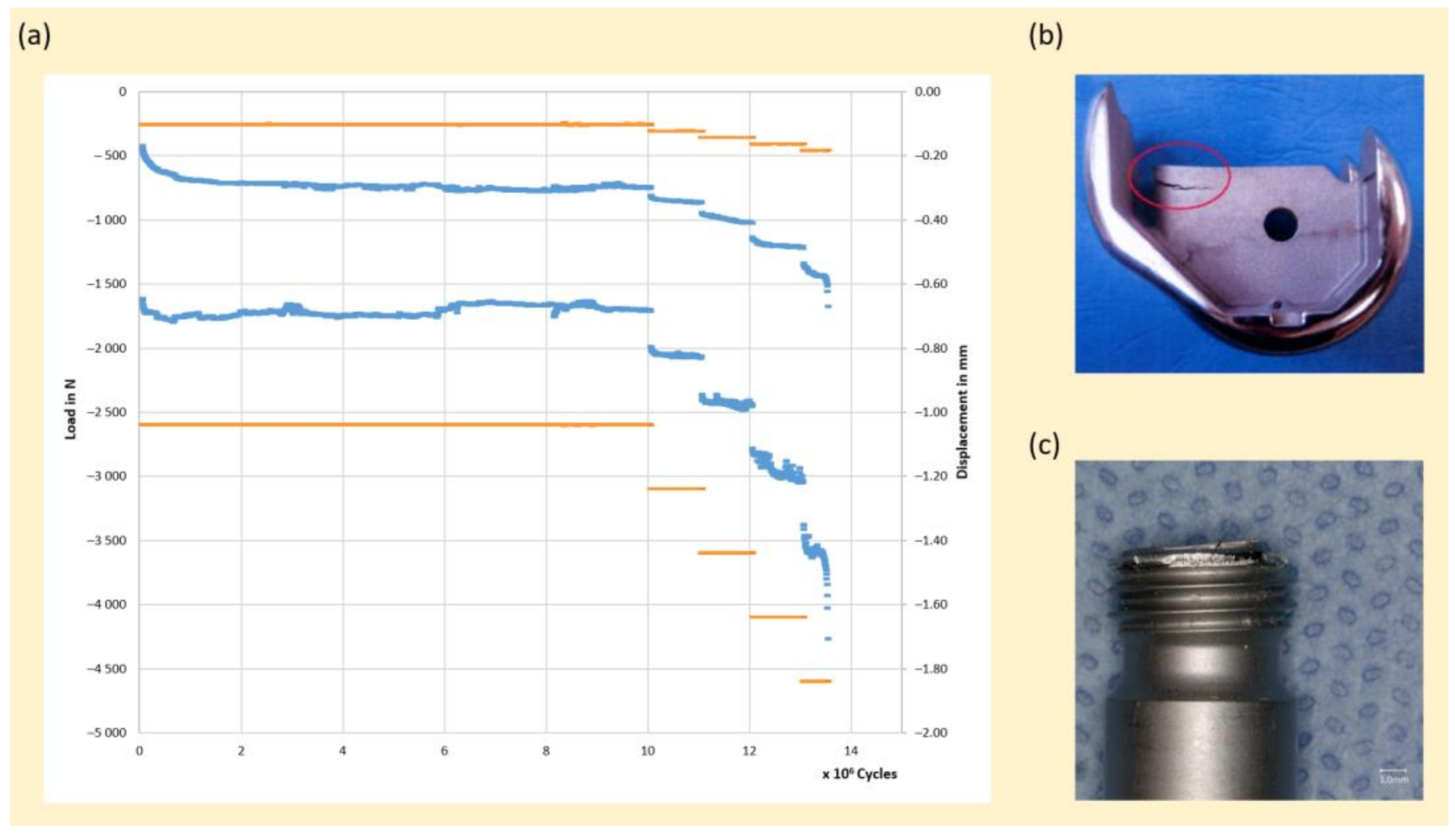
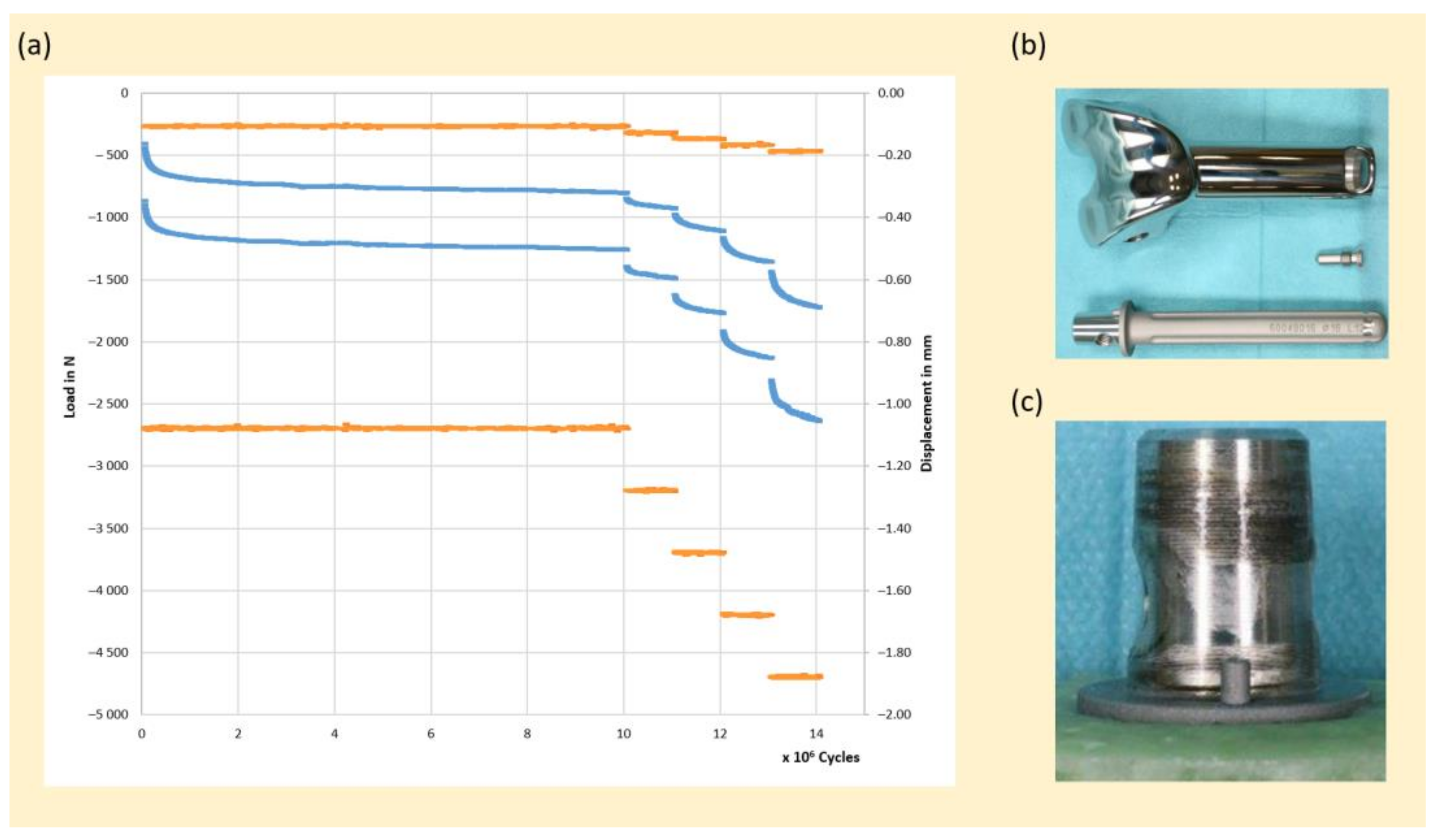
2.3. Biomechanical Test Setup

Biomechanical tests of custom-made implant 1 and reference implant 1 were performed on a hydraulic axial testing system (585 MiniBionix, MTS, Eden Prairie, MN, USA) (Figure 3a,b). Off-the-shelf stems were mounted torque-controlled to reference implant 1 as well as to custom-made implant 1 with 27 Nm. The stems were embedded in casting resin, such that the femoral components were tilted to 7° in the sagittal plane and 9° in the frontal plane. The load was applied via an off-the-shelf meniscus component with a height of 10 mm. In order to avoid shear stress, the interface between load actuator and meniscus component was lubricated with silicone oil such that the meniscus component was able to move freely in horizontal direction. The loading protocol consists of force controlled, sinusoidal compression with a peak load of 2.6 kN and a minimum load of 260 N. This cyclic load was applied with a frequency of 15 Hz for 10,000,000 cycles. The number of cycles is based on well-established standards of orthopedic implants to investigate high cycle fatigue phenomena of metallic components under dynamic loading [23]. In order to analyze the failure mechanism and the safety reserves, both assemblies were tested in addition according to the Locati method. After 10,000,000 cycles, the peak load was increased every 1,000,000 cycles for 500 N, whereby the ratio of minimum to maximum load of 0.1 remained constant. The procedure was stopped at completion of load level 4.6 kN.
The biomechanical tests of custom-made implant 2 and reference implant 2 were performed in two different setups (Figure 3c,d). The investigation was focused on the clinical acceptance of the taper junction itself. This taper junction was developed and tested within a hip assembly, consisting of a trochanteric module and a stem (Figure 3c). Custom-made implant 2 relies on the identical taper junction, yet in a knee assembly (Figure 3d). A biomechanical off-the-shelf knee assembly test with this taper junction was not available. Therefore, the results of the hip assembly test were compared to the results of the knee assembly test. The taper junctions in both biomechanical applications are exposed to combined bending load, such that this comparison was considered acceptable. In accordance with the clinical practice, in the hip assembly the stem was mounted to the Trochanteric module with a hammer punch in the axial direction. The locking screw was mounted using 10 Nm torque-controlled. The stem was embedded in casting resin with a tilt of 10° in the frontal plane and 9° in the sagittal plane. A load-controlled hydraulic axial testing system was used to apply a sinusoidal compression load with a maximum load of 2.3 kN and a minimum load of 230 N with a test frequency of 5 Hz. After 5,000,000 cycles, the load was increased every 1,000,000 cycles by 500 N, whereby the ratio between minimum and maximum load of 0.1 remained constant. The procedure was stopped after completion of load level 4.8 kN. The biomechanical test setup of custom-made implant 2 in the knee assembly (Figure 3d) is analog to the test setup of custom-made implant 1. The mounting of custom-made implant 2 to the stem was performed in accordance with reference implant 2 using a hammer punch and the locking screw was mounted (10 Nm torque controlled). The stem was embedded in casting resin at the proximal end such that a distance between joint line and embedding level of 132 mm resulted. Sinusoidal compression load with a maximum load of 2.7 kN and a minimum load of 270 N was applied for 10,000,000 cycles. After completion of 10,000,000 cycles the peak load was increased every 1,000,000 cycles by 500 N until completion of load level 4.7 kN.

2.4. Finite Element Analysis

FEA models of each biomechanical test setup were developed and solved using ANSYS v 20R2 (ANSYS Inc., Canonsburg, PA, USA). Both reference implants as well as both custom-made implants consist of Cobalt–Chromium alloy, which comprised a modelled linear elastic with a Young’s modulus of 2.2 × 10⁵ MPa and a Poisson’s ratio of 0.32. In order to model the embedding of the stem’s efficiently, an elastic support with a foundation stiffness of 400 N/mm3 was assumed. All parts were meshed with a global element size of 1.5 mm using 3D 10-node tetrahedral structural solid elements (ANSYS Solid187). A sphere of influence at the center of the modular connection with a diameter of 20 mm was defined. In this volume, the mesh was refined to 0.5 mm. The high-stressed faces of the implant components were refined to an element size of 0.125 mm. In total approximately 470,000 elements with 720,000 nodes were used. The used mesh density was based on a convergence study.
Two load steps were calculated in the FEA of custom-made implant 1. In the first load step, the components were mounted (torque controlled with 27 Nm), which was simulated by a screw with axial pre-tension. Since this axial pre-tension depends on the unknown friction coefficient of the screw, the simulation was executed with 5 kN, 8 kN and 10 kN axial pre-tension in order to investigate the sensitivity to this parameter. To simulate the biomechanical test setup, all surfaces below the embedding level were supported elastically to simulate the surrounding embedding material used in laboratory test setup (Figure 2). The frictional contacts in the junction were modeled using the ANSYS frictional contact of 0.2. The load of 2.6 kN was applied on the reference implant (Figure 3a) as well as on the custom-made implant (Figure 3b).
The FEA models of reference implant 2 and custom-made implant 2 were different. Reference implant 2 was tested according to hip standards and custom-made implant 2 according to knee standards. The hip standard requires a performance of 2.3 N for 5,000,000 cycles [24]. However, since the taper junction is applied to a custom-made knee implant, a performance of 2.7 kN for 10,000,000 cycles needs to be fulfilled [25]. The FEA for both implants included four subsequent load steps. In the first step, a mounting of 2 kN was applied to assemble the components. In the second and third steps, the mounting force was withdrawn and pre-tension was applied via the locking screw. The pre-tension was defined as 6.5 kN and varied to 5 kN and 8 kN. In the fourth step, a load of 2.3 kN for reference implant 2 and a load of 2.7 kN for custom-made implant 2 were applied.

3. Results

The suggested method was executed for both custom-made knee implants. The FEA results of the reference implants were compared to the custom-made implants at the load level of the corresponding performance requirements. The findings were then verified by biomechanical tests on each custom-made implant.

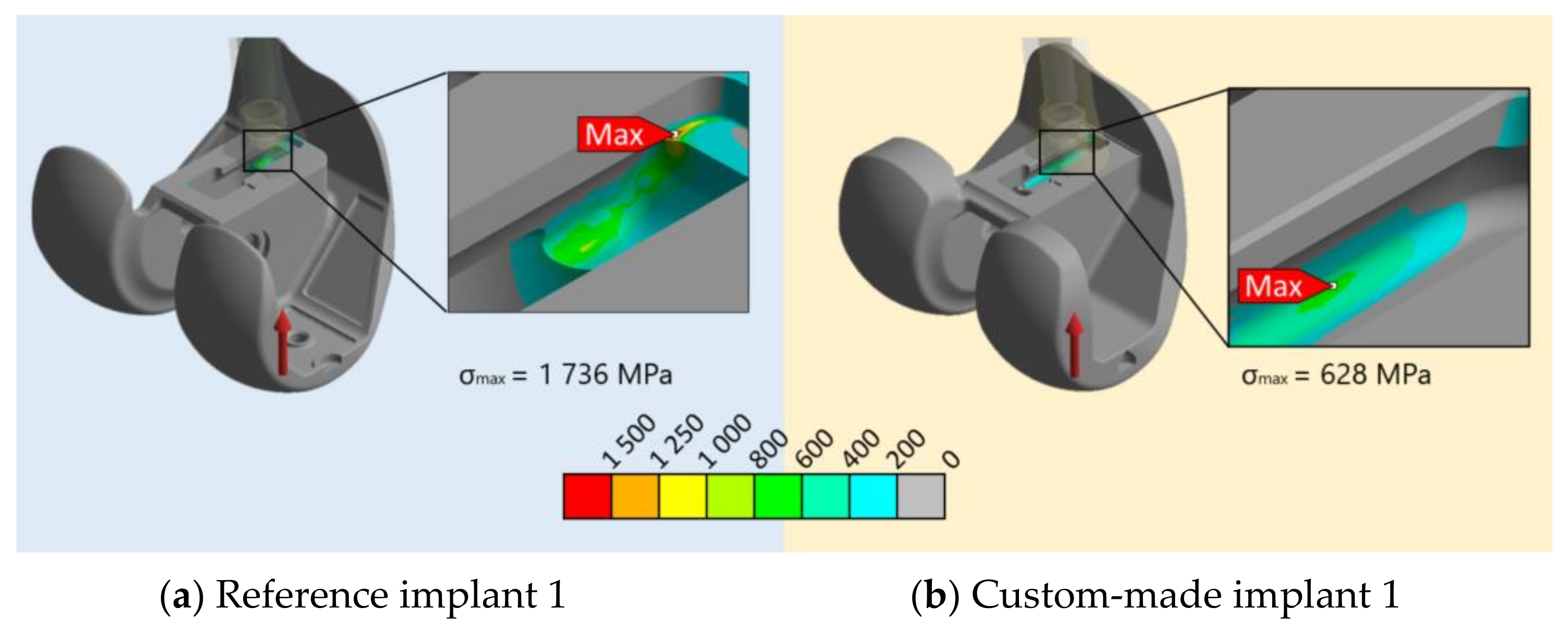
3.1. Custom-Made Implant 1

The biomechanical test of reference implant 1 showed that the implant withstood an axial load of 2.6 kN for 10,000,000 cycles without failure, which implies a fulfillment of the pre-defined acceptance criterion [26]. To identify the safety margin and the failure mechanism, the peak load was increased by 500 N after completion of each 1,000,000 cycles. One sample showed a fracture in the screw and stem in load step 4.6 kN, one sample showed a fracture of the proximal-anterior part of the box at 3.6 kN, and one sample completed the load step of 4.6 kN without any visible failure. It is worth mentioning that implant fracture is inevitable with increasing loads and that the observed failure is not necessarily clinically relevant. For this specific off-the-shelf implant, several studies and register data demonstrate that this implant provides reliable and durable reconstruction of the knee joint [27,28,29].
The FEAs of reference implant 1 and custom-made implant 1 were performed with screw pre-tension values of 5 kN, 8 kN and 10 kN. Obtained values of tensile stress, van Mises stress and micromotion were compared between reference implant 1 and custom-made implant 1, in terms of absolute values and relative values (Table 2). Custom-made implant 1 showed a maximum tensile stress of 36% and a maximum van Mises stress of 74% and 76%, compared to reference implant 1, respectively. Custom-made implant 1 showed a maximum micromotion of 113% at a screw pre-tension of 5 kN compared to reference implant 1. With increased screw pre-tension to 8 kN and 10 kN, the maximum micromotion of custom-made implant 1 was 68% and 63% compared to reference implant 1, respectively.
The maximum tensile stress of reference implant 1 occurred in the proximal-anterior area of the box (Figure 4a). The maximum tensile stress of custom-made implant 1 was observed in a more posterior area compared to reference implant 1. The observed crack in the second sample of reference implant 1 in the proximal-anterior area of the box could be explained by the high tensile stress in this area (Figure 4a and Figure 5b).
The FEA results of custom-made implant 1 were verified by a biomechanical test. This test showed that the implant withstood a cyclic loading of 2.6 kN for 10,000,000 cycles without any visible failure and fulfilled, thereby, the required performance criteria. The observed displacement was in an expectable range (Figure 5a). A stepwise increase in the peak load of 500 N after completion of every 1,000,000 cycles led to a fracture of the screw at a load level of 4.6 kN after 13,485,000 cycles (Figure 5c).

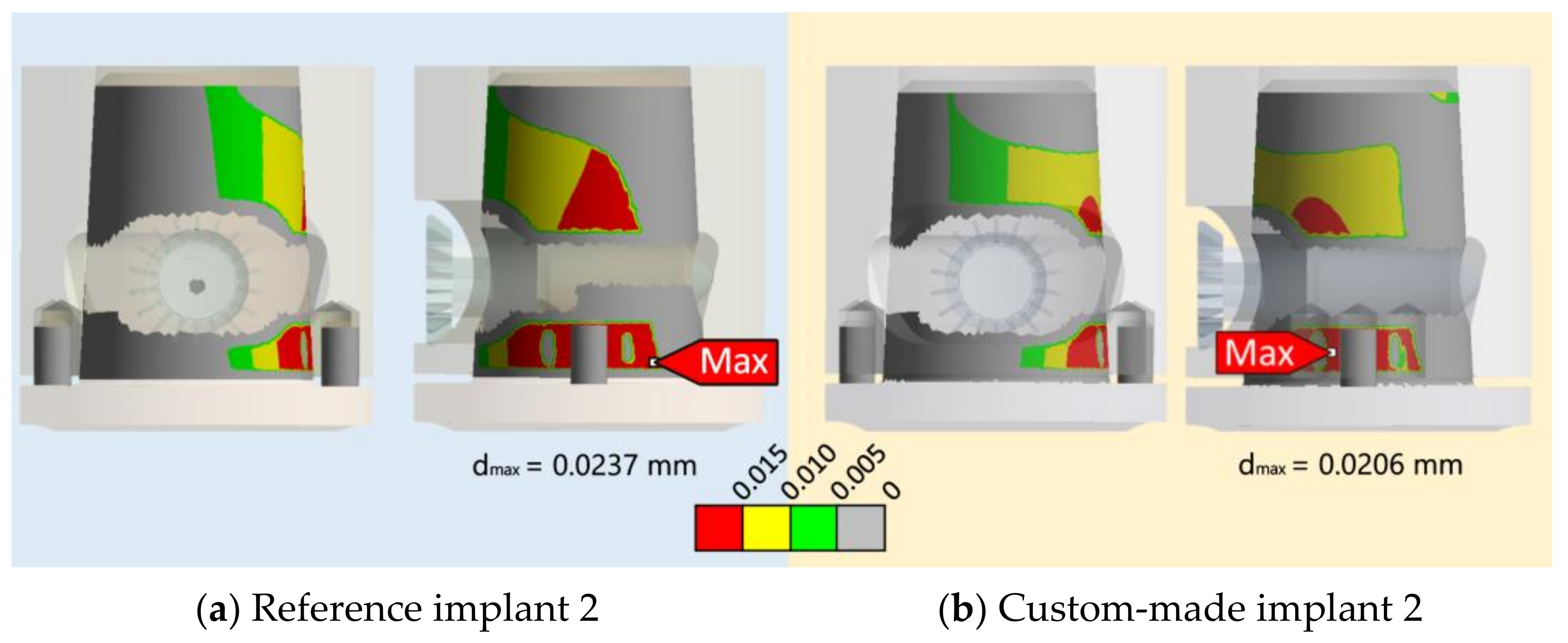
3.2. Custom-Made Implant 2

A biomechanical test on the taper junction of reference implant 2 showed that the assembly withstood cyclic loading, with a peak load of 2.3 kN for 5,000,000 cycles and thereby, fulfilled the pre-defined acceptance criterion [30]. A stepwise increase in the peak load by 500 N after completion of each 1,000,000 cycles showed no macroscopic damage to the taper junction. The procedure was stopped after completion of load step 4.8 kN.
Since the taper junction was applied to a knee implant, the simulated load level of the custom-made implant was 2.7 kN. In both FEAs, the screw pre-tension values were assumed to be 5 kN, 6.5 kN and 8 kN. Obtained values of tensile stress, van Mises stress and micromotion were compared between reference implant 2 and custom-made implant 2, in terms of absolute values and relative values (Table 3). The values for maximum micromotion, as the main failure mechanism, were lower in custom-made implant 2 compared to reference implant 2. Depending on the screw pre-tension, the relative values of maximum micromotion of custom-made implant 2 were 91%, 87%, and 82% compared to reference implant 2. The values for maximum tensile stress and maximum van Mises stress were higher in custom-made implant 2 compared to reference implant 2 and were in a range between 120% and 127%.
The micromotion distributions were similar between reference implant 2 and custom-made implant 2 (Figure 6). The locations of the maximum values in both implants are at the bottom of the taper junction, in the direction of the fixation screw, on the side where the loads were applied. During load application, the taper junction gets compressed, whereby, at the load side, more micromotion was observed. Yet, maximum micromotion values of 0.0237 mm and 0.0206 mm are small and in a range where only negligible fretting corrosion would be expected.
The micromotion distribution of custom-made implant 2 showed a similar pattern compared to the tested taper junction (Figure 7c). The areas of contact were visible with a characteristic pattern of moderate fretting corrosion, yet no severe macroscopic fretting corrosion damage could be observed.
The FEA results of custom-made implant 2 were also verified in a biomechanical test. The test showed that the assembly withstood cyclic loading with a peak load of 2.7 kN for 10,000,000 cycles without failure and thereby, fulfilled the required acceptance criterion. A stepwise increase of 500 N after completion of each 1,000,000 cycles showed no macroscopic failure in the taper junction (Figure 7b). The procedure was stopped after completion of load step 4.7 kN (Figure 7a).

4. Discussion

Unique design characteristics and limited available supply time may impede profound pre-clinical in vitro biomechanical testing of custom-made knee implants. An individual simulation of the biomechanical testing via FEA does not yield a conclusion, since an acceptance criterion for the FEA results cannot be defined in advance. For cases where the custom-made knee implant is comparable to a reference implant (in terms of intended use, design, material, bone–implant interface, and manufacturing) and a biomechanical test of this reference implant is available, this study suggests a method to draw a conclusion on the suitability of the design of a custom-made implant solely based on FEA results.
The suggested method comprises six steps: (1) identification of the main potential failure mechanism and its corresponding FEA quantity of interest, (2) reproduction of the biomechanical test of the reference implant via FEA, (3) identification of the maximum value of the corresponding FEA quantity of interest at the required load level, (4) definition of this value as the acceptance criterion for the FEA of the custom-made implant, (5) reproduction of the biomechanical test with the custom-made implant via FEA, (6) conclusion, whether the acceptance criterion is fulfilled or not. The method was applied to two exemplary custom-made knee implants. It is hypothesized that the mechanical performance of these two custom-made implants can be evaluated solely by FEA.
In custom-made implant 1, a geometrical modification of reference implant 1 had to be evaluated. In accordance with the suggested method, (1) mechanical fatigue was identified as the main potential failure mechanism, with tensile stress as the corresponding FEA quantity of interest, (2) the biomechanical test of reference implant 1 was reproduced by FEA, where (3) a maximum tensile stress of 1 736 MPa resulted. (4) This maximum tensile stress was defined as the acceptance criterion for the FEA of custom-made implant 1. (5) The FEA of custom-made implant 1 revealed a maximum tensile stress of 628 MPa, which (6) implied that the acceptance criterion was fulfilled. In custom-made implant 2, the taper junction from an off-the-shelf implant to a custom-made implant had to be evaluated. Therefore, (1) fretting and corrosion at the taper junction was identified as the main potential failure mechanism with micromotion as its corresponding FEA quantity of interest, (2) the biomechanical test of reference implant 2 was reproduced by FEA, where (3) a maximum micromotion of 0.0237 mm resulted. (4) This maximum micromotion was defined as the acceptance criterion for the FEA of custom-made implant 2. (5) The FEA of custom-made implant 2 revealed a maximum micromotion of 0.0206 mm, which (6) implied that the acceptance criterion for custom-made implant 2 was fulfilled.
In order to validate the FEA results, both custom-made implants were manufactured and biomechanically tested. The biomechanical tests were performed according to the required standards for off-the-shelf knee implants. Both custom-made implants withstood the required mechanical loading and fulfilled the acceptance criterion. For these two examples, the hypothesis could be proven.
The employment of computer modelling and simulation to evaluate the safety and efficacy of a medical product are referred to as in silico trials. Recently, in silico trials have been considered as a new methodology for the regulatory evaluation of a medical product [30]. It is our view that the use of in silico trials could augment and complement clinical in vivo studies [31,32,33]. Previously, FEA studies were commonly used to predict the clinical behavior of different knee implant aspects, for example, wear performance of the polyethylene inlay [34], tibial malalignment [35] or micromotion on a modular taper connection [36]. The approach to reproduce and validate biomechanical tests via FEA and use these measures as a reference for further mechanical implant design modifications has been used in a very interesting study on an energy-harvesting system in an instrumented hip stem [37]. Another common application of FEA in the context of knee implants is the identification of worst-case scenarios of implant combinations, in order to perform the required pre-clinical biomechanical tests only with the implant assembly of the worst-case scenario [38].
The suggested method in this study focused on the pre-clinical testing of custom-made knee implants. The strength of the method is that pre-clinical mechanical evaluation of a custom-made implant, which is often constrained by unique design characteristics and limited supply time, could be performed solely by FEA. Such an in silico trial could support the benefit–risk analysis of a custom-made knee implant. The design of the custom-made implant and its mechanical performance can be assessed without a time-consuming biomechanical test. Thereby, potential flaws in the design and/or potential improvements can be identified and discussed with the responsible surgeons, in order to provide an optimized and safe custom-made implant for the patient. Furthermore, the method provides a quantitative evaluation of the custom-made implant, in addition to the qualitative evaluation of surgeons’ and engineers’ experience. The strength of the study is that the method was applied to two exemplary custom-made implants to compare in silico results with in vitro results.
The study and its method have several limitations. A first limitation is that the application to two exemplary custom-made implants with only one test sample each does not validate a method. The application at these two examples aimed to vividly present the method and to show a proof of concept. A validation of the method should include a larger number of cases, which cover several different modifications. Nevertheless, the proposed method may provide, already at this early stage, benefit to patients, since potential design flaws could be revealed. A second limitation is that different geometrical designs impair the transferability of the biomechanical test results from the reference implant to the custom-made implant. As highlighted above, the comparability of the custom-made implant and the reference implant is a prerequisite of the method. In this study, different manufacturing techniques were applied. The raw parts of the reference implants were manufactured by casting, whereby the raw parts of the custom-made implants were manufactured by additive manufacturing. Both manufacturing methods are validated and fulfill the mechanical requirements defined by the corresponding standard [39,40], such that the manufacturing technique with respect to mechanical properties could be considered as comparable. The third and main limitation of the study and its method is that it massively underestimates the highly complex mechanical evaluation of knee implant assemblies with its multiple dependencies, which cannot be reduced to the result of one FEA quantity of interest. The method supports the assessment of the mechanical properties of a unique custom-made implant by providing a quantitative comparison to a reference implant. The decision regarding whether a design of a custom-made implant is acceptable or not is multifactorial and several additional aspects need to be considered. This also implies that in cases when the acceptance criterion of the custom-made implant is not fulfilled, it does not necessarily mean that the design is unacceptable and a potential biomechanical test or clinical application would fail. The acceptance criterion for the FEA is defined at the required load level of the corresponding standard. However, the biomechanical tests of the reference implants showed that a stepwise increase in the load does not lead to mechanical failure. The FEA acceptance criteria could also be defined at the load level where the biomechanical test procedure stopped without mechanical failure (i.e., 4.8 kN for reference implant 2) and then use this FEA value as an acceptance criterion for the custom-made implant at the load level defined by the standards (i.e., 2.7 kN for custom-made implant 2). This would lead to a more offensive application of the method. In any case, a careful interpretation of the results and the consideration of additional aspects is mandatory. Furthermore, the evaluation is based on the credibility of the used finite element models to replicate the biomechanical test in silico. Inadequate validation and verification activities could have a high impact on the results. The used models for this study were assessed using the standardized Method of ASME V&V 40 [19]. Nevertheless, validation activities would be further improved if a direct measurement of QoIs in the biomechanical tests (e.g., by means of digital image correlation) and, thus, a quantitative comparison to the simulation results, could be performed.
The method should be applied in potential future studies to assess the mechanical properties of different custom-made implants and their corresponding reference implants in an increased number of test samples. Based on such comprehensive investigations, the credibility and borders of the method could be established. Furthermore, the method could also be used to investigate the mechanical effects of misaligned custom-made implants compared to well-aligned implants. For example, in cases where a certain patient anatomy allows only a specific orientation, which is outside the recommended orientation, the application of the method could provide a quantitative comparison to the recommended orientation of the tested reference implant and thereby, a conclusion on whether this specific orientation is acceptable in terms of mechanical endurance properties. The aim is to derive and validate a guideline, which may support surgeons and engineers in the pre-clinical mechanical assessment of custom-made implants.

5. Conclusions

Pre-clinical mechanical assessment of custom-made implants is very challenging. The sole employment of FEA does not yield a conclusion, since an acceptance criterion cannot be defined due to a missing comparator. A comparable reference implant could provide the required comparator and thereby, the acceptance criterion. This study suggests a method where the biomechanical test and FEA results of a reference implant are compared to the FEA results of a custom-made implant. The method was applied to two exemplary custom-made implants, which fulfill the acceptance criteria in the FEAs, as well as in the biomechanical tests. In custom-made implant 1, it could be shown that a more anterior position of the stem interconnection with an appropriate design does not lead to an increased tensile stress compared to corresponding reference implant 1. In the second example, it could be shown that a taper junction, which was originally tested in a hip implant assembly and then applied to a knee implant assembly, led to decreased micromotion. This method could support surgeons and engineers in their decision on whether a design of a custom-made knee implant is acceptable in terms of mechanical endurance properties.

Author Contributions

Conceptualization, G.H., J.-B.W., B.W. and T.M.G.; methodology, G.H. and J.-B.W.; software, J.-B.W.; investigation, G.H., J.-B.W. and B.W.; writing—original draft preparation, G.H.; writing—review and editing, J.-B.W., B.W. and T.M.G.; visualization, G.H. and J.-B.W.; supervision, T.M.G. All authors have read and agreed to the published version of the manuscript.

Funding

This research received no external funding.

Institutional Review Board Statement

Not applicable.

Informed Consent Statement

Not applicable.

Data Availability Statement

Not applicable.

Acknowledgments

The authors would like to thank Bernhard “Bernd” Fritz for conducting the biomechanical experiments, as well as Carli Vizak for her support in improving the language and spelling of the manuscript. The authors would also like to thank Jörg Lützner and Alexander L. Boerboom for the collaboration on the two custom-made implants.

Conflicts of Interest

G.H., J.-B.W. and T.M.G. are employees of Aesculap AG, B.W. is an employee of AQ Solutions GmbH, both manufacturers of orthopedic implants. Aesculap AG and AQ Solutions GmbH provided support in the form of salaries, but did not have any role in the design of the study, data analysis, decision to publish or manuscript preparation.

References

  1. Papagelopoulos, P.J.; Savvidou, O.D.; Koutsouradis, P.; Chloros, G.D.; Bolia, I.K.; Sakellariou, V.I.; Kontogeorgakos, V.A.; Mavrodontis, I.I.; Mavrogenis, A.F.; Diamantopoulos, P. Three-dimensional Technologies in Orthopedics. Orthopedics 2018, 41, 12–20. [Google Scholar] [CrossRef] [PubMed]
  2. Camarda, L.; D’Arienzo, A.; Morello, S.; Peri, G.; Valentino, B.; D’Arienzo, M. Patient-specific instrumentation for total knee arthroplasty: A literature review. Musculoskelet. Surg. 2015, 99, 11–18. [Google Scholar] [CrossRef] [PubMed]
  3. Hafez, M.A.; Moholkar, K. Patient-specific instruments: Advantages and pitfalls. SICOT J 2017, 3, 66. [Google Scholar] [CrossRef] [PubMed]
  4. Victor, J.; Vermue, H. Custom TKA: What to expect and where do we stand today? Arch. Orthop. Trauma Surg. 2021, 141, 2195–2203. [Google Scholar] [CrossRef]
  5. Levengood, G.A.; Dupee, J. Accuracy of Coronal Plane Mechanical Alignment in a Customized, Individually Made Total Knee Replacement with Patient-Specific Instrumentation. J. Knee Surg. 2018, 31, 792–796. [Google Scholar] [CrossRef] [Green Version]
  6. Beit Ner, E.; Dosani, S.; Biant, L.C.; Tawy, G.F. Custom Implants in TKA Provide No Substantial Benefit in Terms of Outcome Scores, Reoperation Risk, or Mean Alignment: A Systematic Review. Clin. Orthop. Relat. Res. 2021, 479, 1237–1249. [Google Scholar] [CrossRef]
  7. McNamara, C.A.; Gösthe, R.G.; Patel, P.D.; Sanders, K.C.; Huaman, G.; Suarez, J.C. Revision total knee arthroplasty using a custom tantalum implant in a patient following multiple failed revisions. Arthroplast. Today 2017, 3, 13–17. [Google Scholar] [CrossRef] [Green Version]
  8. Burastero, G.; Pianigiani, S.; Zanvettor, C.; Cavagnaro, L.; Chiarlone, F.; Innocenti, B. Use of porous custom-made cones for meta-diaphyseal bone defects reconstruction in knee revision surgery: A clinical and biomechanical analysis. Arch. Orthop. Trauma Surg. 2020, 140, 2041–2055. [Google Scholar] [CrossRef]
  9. Savov, P.; Tuecking, L.-R.; Windhagen, H.; Ettinger, M. Individual Revision Knee Arthroplasty Is a Safe Limb Salvage Procedure. J. Pers. Med. 2021, 11, 572. [Google Scholar] [CrossRef]
  10. MacKenzie, E.J.; Jones, A.S.; Bosse, M.J.; Castillo, R.C.; Pollak, A.N.; Webb, L.X.; Swiontkowski, M.F.; Kellam, J.F.; Smith, D.G.; Sanders, R.W.; et al. Health-care costs associated with amputation or reconstruction of a limb-threatening injury. J. Bone Joint Surg. Am. 2007, 89, 1685–1692. [Google Scholar] [CrossRef]
  11. IMDRF. Definitions for Personalized Medical Devices: IMDRF; IMDRF: Brussels, Belgium, 2021. [Google Scholar]
  12. MDCG. Questions and Answers on Custom-Made Devices: MDCG 2021-3; MDCG: Brussels, Belgium, 2021. [Google Scholar]
  13. European Union. REGULATION (EU) 2017/745 OF THE EUROPEAN PARLIAMENT AND OF THE COUNCIL of 5 April 2017 on Medical Devices, Amending Directive 2001/83/EC, Regulation (EC) No 178/2002 and Regulation (EC) No 1223/2009 and Repealing Council Directives 90/385/EEC and 93/42/EEC: MDR 2017/745; European Union: Brussels, Belgium, 2017. [Google Scholar]
  14. Wehmöller, M.; Utz, M.; Gesche, V. Digital process chains for patient specific medical devices. Curr. Dir. Biomed. Eng. 2020, 6, 357–359. [Google Scholar] [CrossRef]
  15. Martinez-Marquez, D.; Terhaer, K.; Scheinemann, P.; Mirnajafizadeh, A.; Carty, C.P.; Stewart, R.A. Quality by Design for industry translation: Three-dimensional risk assessment failure mode, effects, and criticality analysis for additively manufactured patient-specific implants. Eng. Rep. 2020, 2, e12113. [Google Scholar] [CrossRef]
  16. VDI-Gesellschaft Technologies of Life Sciences. Digitale Prozessketten in der Industriellen Medizintechnik—Herstellung von Sonderanfertigungen: Digital Process Chains in Industrial Manufacturing for Medical Devices—Custom-Made Devices; (VDI 5705:2021); VDI-Gesellschaft Technologies of Life Sciences: Dusseldorf, Germany, 2021. [Google Scholar]
  17. Beuth. DIN EN ISO 13485:2016-08; Medizinprodukte_- Qualitätsmanagementsysteme_- Anforderungen für Regulatorische Zwecke (ISO_13485:2016); Deutsche Fassung EN_ISO_13485:2016; (DIN EN ISO 13485:2016); Beuth Verlag GmbH: Berlin, Germany, 2016. [Google Scholar]
  18. Taylor, M.; Prendergast, P.J. Four decades of finite element analysis of orthopaedic devices: Where are we now and what are the opportunities? J. Biomech. 2015, 48, 767–778. [Google Scholar] [CrossRef] [Green Version]
  19. ASME. Assessing Credibility of Computational Modeling through Verification and Validation: Application to Medical Devices: V V 40-2018; ASME: New York, NY, USA, 2018. [Google Scholar]
  20. Martelli, S.; Taddei, F.; Cristofolini, L.; Gill, H.S.; Viceconti, M. Extensive risk analysis of mechanical failure for an epiphyseal hip prothesis: A combined numerical-experimental approach. Proc. Inst. Mech. Eng. H 2011, 225, 126–140. [Google Scholar] [CrossRef]
  21. Grupp, T.M.; Kaddick, C.; Baxmann, M. Biomechanische Testung in der Orthopädie und Wirbelsäulenchirurgie. Osteologie 2015, 24, 152–157. [Google Scholar] [CrossRef]
  22. Cooper, H.J.; Della Valle, C.J.; Berger, R.A.; Tetreault, M.; Paprosky, W.G.; Sporer, S.M.; Jacobs, J.J. Corrosion at the head-neck taper as a cause for adverse local tissue reactions after total hip arthroplasty. J. Bone Joint Surg. Am. 2012, 94, 1655–1661. [Google Scholar] [CrossRef] [Green Version]
  23. ASTM. Standard Practice for Cyclic Fatigue Testing of Metal Tibial Tray Components of Total Knee Joint Replacements; ASTM: West Conshohocken, PA, USA, 2020. [Google Scholar]
  24. ISO. Chirurgische Implantate—Partieller und Totaler Hüftgelenkersatz—Teil 4: Bestimmung der Dauerwechselfestigkeit und Leistungsanforderungen an Hüftendoprothesenschäfte; ISO: London, UK, 2016. [Google Scholar]
  25. Bergmann, G.; Bender, A.; Graichen, F.; Dymke, J.; Rohlmann, A.; Trepczynski, A.; Heller, M.O.; Kutzner, I. Standardized loads acting in knee implants. PLoS ONE 2014, 9, e86035. [Google Scholar] [CrossRef] [Green Version]
  26. Grupp, T.M.; Giurea, A.; Miehlke, R.K.; Pfaff, A.; Fritz, B.; Schwiesau, J.; Blömer, W. Entwicklung einer achsgeführten Rotationsknieprothese aus biomechanischer Sicht; Design of a rotating hinge knee endoprosthesis from a biomechanical point of view. Abstr. Biomater. 2009, 47. [Google Scholar]
  27. Grimberg, A.; Jansson, V.; Lützner, J.; Melsheimer, O.; Morlock, M.; Steinbrück, A. German Arthroplasty Registry (Endoprothesenregister Deutschland—EPRD); EPRD: Berlin, Germany, 2020. [Google Scholar] [CrossRef]
  28. Vertesich, K.; Staats, K.; Böhler, C.; Koza, R.; Lass, R.; Giurea, A. Long Term Results of a Rotating Hinge Total Knee Prosthesis with Carbon-Fiber Reinforced Poly-Ether-Ether-Ketone (CFR-PEEK) as Bearing Material. Front. Bioeng. Biotechnol. 2022, 10, 845859. [Google Scholar] [CrossRef]
  29. Böhler, C.; Kolbitsch, P.; Schuh, R.; Lass, R.; Kubista, B.; Giurea, A. Midterm Results of a New Rotating Hinge Knee Implant: A 5-Year Follow-Up. Biomed Res. Int. 2017, 2017, 7532745. [Google Scholar] [CrossRef] [Green Version]
  30. Kremling, U.; Gatzke, F. Cyclic Fatigue Test on a Modified Intramedullary Adapter Stem of the Modular Tumor/Revision System “MML”. 2012. [Google Scholar]
  31. Favre, P.; Maquer, G.; Henderson, A.; Hertig, D.; Ciric, D.; Bischoff, J.E. In Silico Clinical Trials in the Orthopedic Device Industry: From Fantasy to Reality? Ann. Biomed. Eng. 2021, 49, 3213–3226. [Google Scholar] [CrossRef] [PubMed]
  32. Viceconti, M.; Pappalardo, F.; Rodriguez, B.; Horner, M.; Bischoff, J.; Musuamba Tshinanu, F. In silico trials: Verification, validation and uncertainty quantification of predictive models used in the regulatory evaluation of biomedical products. Methods 2021, 185, 120–127. [Google Scholar] [CrossRef] [PubMed]
  33. Viceconti, M.; Emili, L.; Afshari, P.; Courcelles, E.; Curreli, C.; Famaey, N.; Geris, L.; Horner, M.; Jori, M.C.; Kulesza, A.; et al. Possible Contexts of Use for In Silico Trials Methodologies: A Consensus-Based Review. IEEE J. Biomed. Health Inform. 2021, 25, 3977–3982. [Google Scholar] [CrossRef] [PubMed]
  34. Koh, Y.-G.; Park, K.-M.; Lee, H.-Y.; Park, J.-H.; Kang, K.-T. Prediction of wear performance in femoral and tibial conformity in patient-specific cruciate-retaining total knee arthroplasty. J. Orthop. Surg. Res. 2020, 15, 24. [Google Scholar] [CrossRef]
  35. Suh, D.-S.; Kang, K.-T.; Son, J.; Kwon, O.-R.; Baek, C.; Koh, Y.-G. Computational study on the effect of malalignment of the tibial component on the biomechanics of total knee arthroplasty: A Finite Element Analysis. Bone Joint Res. 2017, 6, 623–630. [Google Scholar] [CrossRef]
  36. Bitter, T.; Khan, I.; Marriott, T.; Lovelady, E.; Verdonschot, N.; Janssen, D. Finite element wear prediction using adaptive meshing at the modular taper interface of hip implants. J. Mech. Behav. Biomed. Mater. 2018, 77, 616–623. [Google Scholar] [CrossRef]
  37. Lange, H.-E.; Bader, R.; Kluess, D. Endurance testing and finite element simulation of a modified hip stem for integration of an energy harvesting system. Proc. Inst. Mech. Eng. H 2021, 235, 985–992. [Google Scholar] [CrossRef]
  38. ASTM. Standard Practice for Finite Element Analysis (FEA) of Metallic Orthopaedic Total Knee Tibial Components; ASTM: West Conshohocken, PA, USA, 2019. [Google Scholar]
  39. ASTM. Standard for Additive Manufacturing—Finished Part Properties—Standard Specification for Cobalt-28 Chromium-6 Molybdenum via Powder Bed Fusion; ASTM International: West Conshohocken, PA, USA, 2018. [Google Scholar]
  40. ASTM. Specification for Cobalt-28 Chromium-6 Molybdenum Alloy Castings and Casting Alloy for Surgical Implants (UNS R30075); ASTM International: West Conshohocken, PA, USA, 2019. [Google Scholar]
Figure 1. Pre-clinical biomechanical testing. (a) Biomechanical test of an off-the-shelf implant with a pre-defined acceptance criterion leads to certain conclusion. (b) A finite element analysis (FEA) of a custom-made implant does not yield to a conclusion since the acceptance criterion for the FEA cannot be defined in advance. (c) An FEA of the custom-made implant yields to a conclusion when using the outputs of the biomechanical test and of the FEA of the reference implant as the acceptance criterion for the custom-made implant.
Applsci 12 04787 g001
Figure 2. Overview of the biomechanical and finite element analysis test method. Sodium chloride (NaCl).
Applsci 12 04787 g002
Figure 3. Biomechanical test and finite element analysis setup of (a) reference implant 1, (b) custom-made implant 1, (c) reference implant 2, and (d) custom-made implant 2. Multi-point constraint (MPC), Quantity of interest (QoI).
Applsci 12 04787 g003
Figure 4. Reference implant 1 and custom-made implant 1. (a) Maximum tensile stress (σmax) and tensile stress distribution of reference implant 1 as well as (b) custom-made implant 1.
Applsci 12 04787 g004
Figure 5. Experimental results of custom-made implant 1. (a) Load and displacement curves relative to cycles. (b) Mechanical fracture of one sample of reference implant 1. (c) Fracture of the stem connected to custom-made implant 1.
Applsci 12 04787 g005
Figure 6. FEA results of reference implant 2 and custom-made implant 2. (a) Maximum micromotion (dmax) and micromotion distribution of reference implant 2 and (b) custom-made implant 2.
Applsci 12 04787 g006
Figure 7. Experimental results of custom-made implant 2. (a) Load and displacement relative to cycles. (b) Components of custom-made implant 2 test assembly. (c) Taper junction of the stem connected to custom-made implant 2.
Applsci 12 04787 g007
Table 1. Overview of the custom-made implants.
Custom-Made Implant 1Custom-Made Implant 2
Clinical case and
pre-operative
planning
Applsci 12 04787 i001 Applsci 12 04787 i002 Applsci 12 04787 i003 Applsci 12 04787 i004
Implant
components
Applsci 12 04787 i005 Applsci 12 04787 i006
Main failure
mechanisms
Mechanical fatigue of
proximal-anterior box area
Fretting corrosion at the taper junction
Corresponding
FEA measure
Maximum tensile stressMaximum micromotion
Post-operative
image
Applsci 12 04787 i007 Applsci 12 04787 i008
Table 2. FEA results of custom-made implant 1.
Max. Tensile Stress [MPa]Max. Van Mises Stress [MPa]Max. Micromotion [mm]
Screw Tension5 kN8 kN10 kN5 kN8 kN10 kN5 kN8 kN10 kN
Reference implant1381
100%
1736
100%
2020
100%
1734
100%
1736
100%
1801
100%
0.171
100%
0.0232
100%
0.0197
100%
Custom-made
implant
509
36%
628
36%
725
36%
1283
74%
1283
74%
1376
76%
0.194
113%
0.0159
68%
0.0124
63%
Table 3. FEA results of custom-made implant 2.
Max. Tensile Stress [MPa]Max. Van Mises Stress [MPa]Max. Micromotion [mm]
Screw Tension5 kN6.5 kN8 kN5 kN6.5 kN8 kN5 kN6.5 kN8 kN
Reference implant551
100%
660
100%
772
100%
571
100%
637
100%
731
100%
0.0247
100%
0.0237
100%
0.0227
100%
Custom-made
implant
697
126%
818
124%
940
121%
687
120%
807
126%
927
127%
0.0225
91%
0.0206
87%
0.0187
82%
Publisher’s Note: MDPI stays neutral with regard to jurisdictional claims in published maps and institutional affiliations.

