Article

Iridescent Perfect Absorption in Critically-Coupled Acoustic Metamaterials Using the Transfer Matrix Method

Laboratoire d’Acoustique de l’Université du Maine (LAUM)-CNRS UMR 6613, Av. Olivier Messiaen, 72085 Le Mans, France
*
Author to whom correspondence should be addressed.
Submission received: 31 May 2017 / Revised: 7 June 2017 / Accepted: 12 June 2017 / Published: 14 June 2017
(This article belongs to the Section Acoustics and Vibrations)

Abstract

:
The absorption performance of a locally-reacting acoustic metamaterial under oblique incidence is studied. The metamaterial is composed of a slotted panel, each slit being loaded by an array of Helmholtz resonators. The system is analytically studied using the transfer matrix method, accounting for the viscothermal losses both in the resonator elements and in the slits, allowing the representation of the reflection coefficient in the complex frequency plane. We show that by tuning the geometry of the metamaterial, perfect absorption peaks can be obtained on demand at selected frequencies and different angles of incidence. When tilting the incidence angle, the peaks of perfect absorption are shifted in frequency, producing an acoustic iridescence effect similar to the optic iridescence achieved by incomplete band gap. Effectively, we show that in this kind of locally-reacting metamaterial, perfect and omnidirectional absorption for a given frequency is impossible to achieve because the metamaterial impedance does not depend on the incidence angle (i.e., the impedance is a locally reacting one). The system is interpreted in the complex frequency plane by analysing the trajectories of the zeros of the reflection coefficient. We show that the trajectories of the zeros do not overlap under oblique incidence, preventing the observation of perfect and omnidirectional absorption in locally reacting metamaterials. Moreover, we show that for any locally resonant material, the absorption in diffuse field takes a maximal value of 0.951, which is achieved by a material showing perfect absorption for an incidence angle of 50.34 degrees.

1. Introduction

Acoustic absorption is a major topic in acoustics, mainly because acoustic absorbers are broadly used in industry (e.g., in building and civil engineering applications). In these situations, a typical configuration is to place the materials at the walls of a room, the non-reflecting acoustic material being rigidly backed. The classical approach to designing such materials is to produce a porous frame whose scale of porous cavities is on the order of the thermal and viscous boundary layers of the filling host fluid (typically air) [1]. When a porous foam layer is rigidly backed, absorption might be large for frequencies only above the so-called quarter wavelength resonance of the backed layer. Thus, the main limitation of porous material-based absorbers yields in the sound speed inside the absorbers, which is on the same order as the one in the air medium: to efficiently absorb low-frequency sound, the thickness of the layer must be large, because at these frequencies the wavelength in air is on the order of several meters. Peculiar absorption properties are also encountered in composite structures like double porosity materials [2], dead-end porosity materials [3,4], or chirped layered structures [5]. However, it is of special interest to design materials and structures in the form of thin panels (i.e., much smaller than the characteristic wavelength).
In recent years, metamaterials have been used to design sub-wavelength absorbers. These specific materials are artificial structures composed of an arrangement of resonant unit cells—smaller than the characteristic wavelength—that present effective properties not observed in the materials that compose the structure. Examples of such absorbers are metaporous materials [6,7,8,9], metamaterials composed of membrane-type resonators [10,11,12,13], Helmholtz resonators (HRs) [13,14,15,16], and quarter-wavelength resonators (QWRs) [4,17,18,19]. These last types of metamaterials [4,15,16,17,18] make use of strong dispersion, giving rise to slow-sound propagation inside the material. Using slow sound results in a decrease of the cavity resonance frequency, and hence the structure thickness can be reduced to the deep-subwavelength regime [18].
Materials that present perfect absorption are of special interest. This occurs when the leakage of the structure is exactly compensated by the intrinsic losses of the system (i.e., when the material is critically coupled with the exterior media) [13]. For a rigidly backed material, this reduces to the well-known impedance matching conditions. However, the critical coupling conditions can only be fulfilled at a single particular incidence angle for a particular frequency in locally reacting materials, because the effective acoustic impedance does not depend on the direction of propagation. This can reduce the efficiency of the material when used in situations where the incoming acoustic waves impinge the structure in a broad range of angles [1,20].
In this work, we present an ultra-thin acoustic metamaterial presenting perfect absorption at selected angles and frequencies. Thus, it produces an acoustic iridescent effect due to its selective and perfect absorption at particular angles and frequencies. Light iridescence is commonly observed in nature in structured natural phononic materials as occurs in beetles and butterfly wings, fish scales, or bird feathers [21,22], producing strong reflections at selected angles. It has also been proposed to generate acoustic iridescent materials using perforated plates [23]. The structures proposed in this work produce iridescence through perfect absorption at selected angles and frequencies. The specific features of the angle-dependent absorption are illustrated by using the complex frequency plane representation of the reflection coefficient and by showing the trajectories of the different zeros of the reflection coefficient in the complex frequency plane. The fact that these trajectories do not overlap prevents the observation of perfect and omnidirectional absorption in locally reacting metamaterials. The paper is organised as follows: first, in Section 2 the metamaterial and the theoretical model are described; second, the results for oblique incidence using a metamaterial composed of a single resonator per unit cell are shown in Section 3.1; then, examples using multiple resonators are given in Section 3.2. Finally, the discussion and conclusions are provided in Section 4 and Section 5, respectively.

2. Materials and Methods

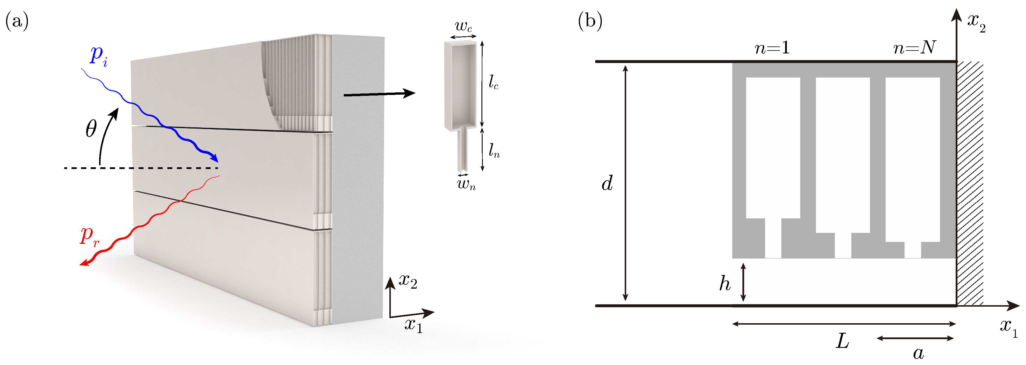
2.1. Description of the System

The sound absorbing metamaterial is composed of a slotted panel of thickness L, each slit being of height h and being loaded by an array of N HRs, as shown in Figure 1. The n-th square cross-section resonator is separated by lattice step a from the preceding one. Its geometry is composed of a neck of length l n ( n ) and side w n ( n ) , and a cavity of length l c ( n ) and side w c ( n ) . Note that the geometry is similar to the one presented in Reference [15], but here we consider an array of different HRs.

2.2. Theoretical Model

The system is analysed theoretically using the transfer matrix method (TMM). Under the assumption of plane waves travelling inside the metamaterial, which is valid for the low frequency regime, the transfer matrix can be obtained, providing directly the reflection of the metamaterial, as well as its effective parameters. Thus, the relation between the pressure, p, and normal particle velocity, v, at the beginning ( x 1 = 0 ) and at the end ( x 1 = L ) of the slits is given by the total transfer matrix of the system, T , as
p v x 1 = 0 = T p v x 1 = L = T 11 T 12 T 21 T 22 p v x 1 = L
The total transfer matrix of the whole system can be obtained by the product of the transfer matrices of each layer of the material. Thus, the total transfer matrix method of the system is given by
T = T 11 T 12 T 21 T 22 = M Δ l slit n = 1 N M s M HR ( n ) M s ,
where M s is the transmission matrix of half lattice step in the slit, M HR ( n ) is the transmission matrix of the n-th resonator, and M Δ l slit the radiation correction of the slits (i.e., the “end” correction [24]) that mimics the effect of the higher-order modes. The transmission matrix for each lattice step in the slit is written as
M s = cos k s a / 2 i Z s sin k s a / 2 i sin k s a / 2 / Z s cos k s a / 2 ,
where Z s is the slit characteristic impedance, written as Z s = κ s ρ s / S s , k s is the wavenumber in the slit, and S s = h a . The complex and frequency-dependent effective bulk modulus and density accounting for the thermoviscous losses, κ s and ρ s , respectively, are given below. The HRs—introduced as point scatterers—and the radiation correction of the slits are given by the following transfer matrices:
M HR ( n ) = 1 0 1 / Z HR ( n ) 1 , M Δ l slit = 1 Z Δ l slit 0 1 ,
with Z HR ( n ) the impedance of the n-th HR and Z Δ l slit the characteristic radiation impedance given by Z Δ l slit = - i ω Δ l slit ρ 0 / ϕ t S 0 , where S 0 = d a , ρ 0 is the air density, and Δ l slit the radiation correction for a periodic distribution of slits [24].
Eventually, after some algebra, it can be shown that under oblique incidence of angle θ , the reflection coefficient of the rigidly-backed material can be directly calculated from the elements of the matrix T as
R ( θ ) = T 11 cos ( θ ) - Z 0 T 21 T 11 cos ( θ ) + Z 0 T 21 ,
with Z 0 = ρ 0 c 0 / S 0 the impedance of air. Finally, the absorption is obtained as α = 1 - R 2 . The effective parameters of each slit can be obtained from the transfer matrix elements as follows
k eff = 1 L cos - 1 T 11 + T 22 2 , Z eff = T 12 T 21 .
Note that the TMM using a similar metamaterial has been validated using finite element simulations, modal expansion, effective parameters, and experiments in References [15,16].

2.3. Visco-Thermal Losses Model

The visco-thermal losses in the system are considered both in the resonators and in the slits by using its effective complex and frequency dependent parameters [25]. On the one hand, the effective parameters in the slits are given by
ρ s = ρ 0 1 - tanh h 2 G ρ h 2 G ρ - 1 , κ s = κ 0 1 + ( γ - 1 ) tanh h 2 G κ h 2 G κ - 1 ,
with G ρ = i ω ρ 0 / η and G κ = i ω Pr ρ 0 / η , and where γ is the specific heat ratio of air, P 0 is the atmospheric pressure, Pr is the Prandtl number, η the dynamic viscosity, ρ 0 the air density, and κ 0 = γ P 0 the air bulk modulus. On the other hand, the complex and frequency-dependent density and bulk modulus in a rectangular cross-section tube are given by [25]:
ρ e f f = - ρ 0 a 2 b 2 4 G ρ 2 k N m N α k 2 β m 2 α k 2 + β m 2 - G ρ 2 - 1 ,
κ e f f = κ 0 γ + 4 ( γ - 1 ) G κ 2 a 2 b 2 k N m N α k 2 β m 2 α k 2 + β m 2 - G κ 2 - 1 ,
with the constants α k = 2 ( k + 1 / 2 ) π / a and β m = 2 ( m + 1 / 2 ) π / b , and the dimensions of the duct a and b being either the neck, a = b = w n ( n ) , or the cavity, a = b = w c ( n ) of the n-th Helmholtz resonator. Using the effective parameters for the neck and cavity elements given by Equations (7) and (8), the impedance of a Helmholtz resonator including the thermoviscous losses and the “end” correction due to the radiation can be obtained [26].

3. Results

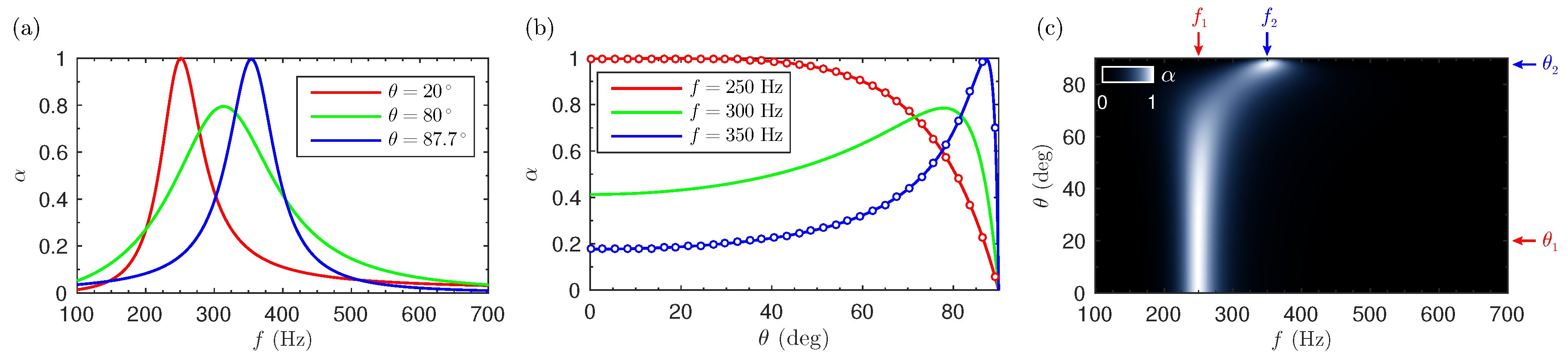
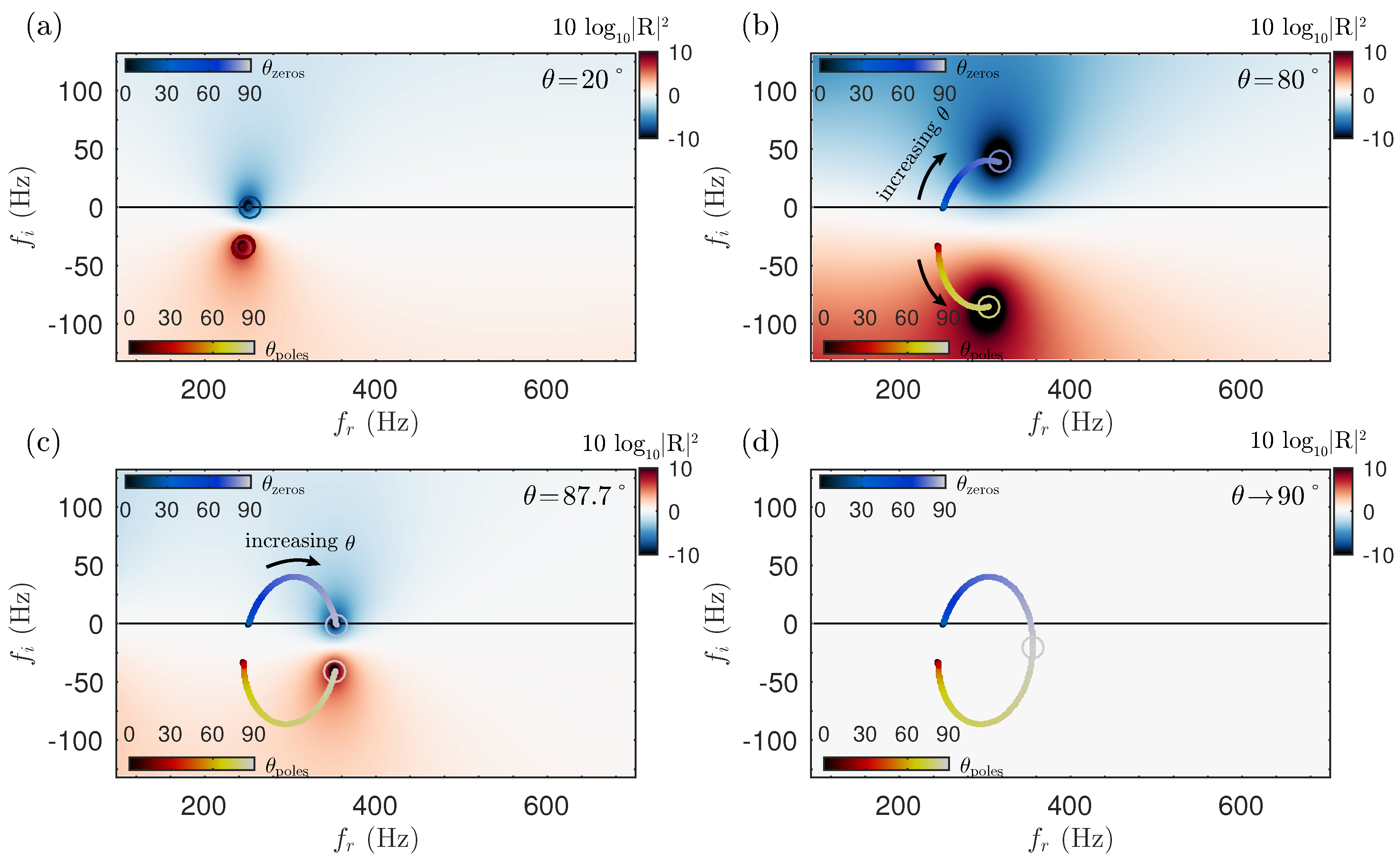
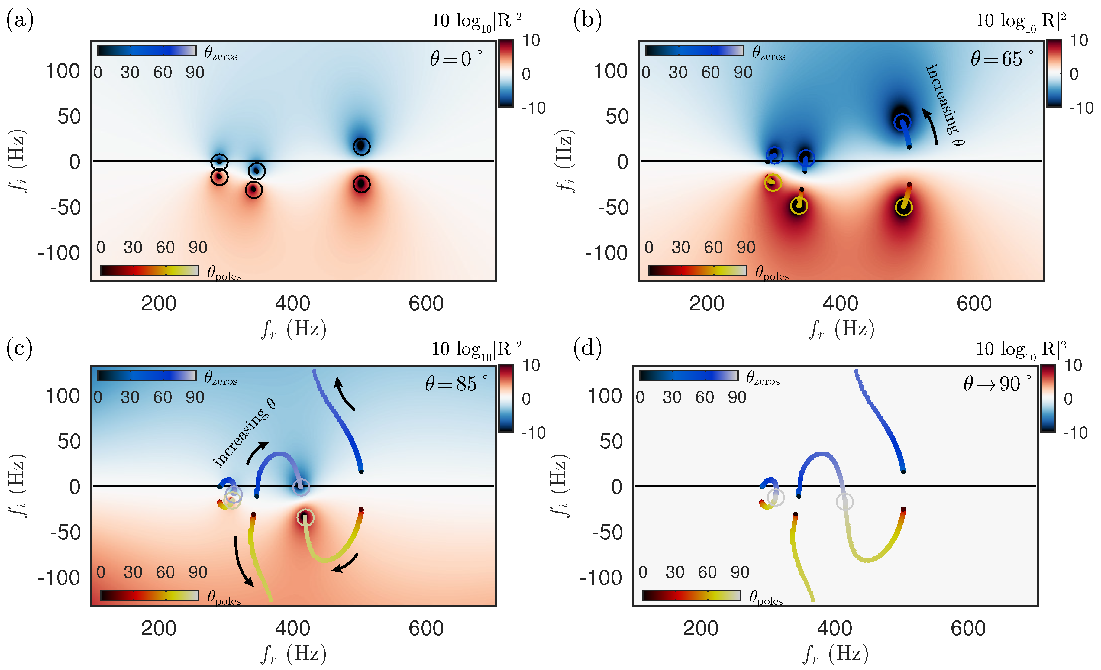
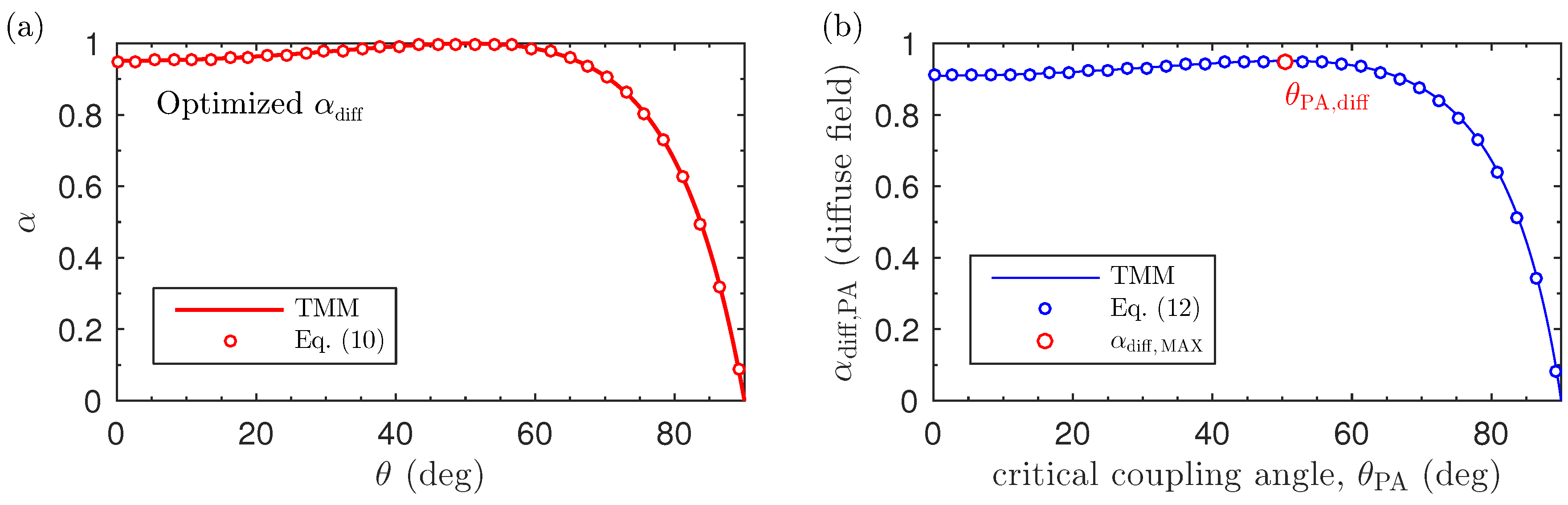
3.1. Perfect Absorption under Oblique Incidence

As shown in Reference [15], by tuning the geometrical parameters, the structure described in this work can be impedance matched with the exterior medium, and perfect acoustic absorption can be obtained. For locally reacting materials, this occurs when Equation (4) vanishes, leading to the impedance matching conditions:
Re ( Z ) cos ( θ ) = Z 0 and Im ( Z ) = 0 .
where Z is the acoustic impedance of the rigidly-backed material (i.e., Z = i Z eff cot k eff L ). Thus, for a locally reacting metamaterial whose characteristic effective impedance does not depend on the incident angle, the impedance matching can only be achieved at one single angle for a given frequency. In particular, using Equations (4) and (9), the angle-dependent absorption of a material presenting perfect absorption at a given angle θ P A is given by:
α ( θ ) = 1 - cos θ P A / cos θ - 1 cos θ P A / cos θ + 1 2 ,
where θ P A is the angle at which perfect absorption is produced. For θ = 90 , this equation is undetermined, but in the limit when θ π / 2 , the absorption vanishes if not considering other physical phenomena in the model (see Discussion section).
To illustrate this, we begin by showing the case of a single HR (i.e, N = 1 ). The structure was designed to show a peak of perfect absorption at 250 Hz at θ = 20 . In particular, the cost using in the optimization was ε = 1 - α ( θ n , f n ) with f n = 250 Hz and θ n = 20 , and the geometrical parameters of the structure were varied using only the constraint of d = 5 cm and L = c 0 / 24 f m ; i.e., a structure 14 times smaller than the wavelength at 250 Hz. The optimization algorithm was a sequential quadratic programming [27]. The retrieved parameters are given in Table A1 in the Appendix A. Figure 2a–c show the absorption as a function of the angle and frequency. First, for an incidence angle of θ = 20 , the structure presents a peak of perfect absorption at f P A = 250 Hz, as shown by the red line in Figure 2a. When the incidence angle is increased, the impedance matching condition is no longer fulfilled, and the absorption decreases following Equation (10), as shown by Figure 2b. However, the fact that perfect absorption might not be achieved for other angles at this frequency does not imply that perfect absorption can be obtained at other frequencies. Thus, the mapping of the absorption as a function of the incidence angle and frequency is shown in Figure 2c. It can be observed that by increasing the incidence angle, the absorption peak shifts to higher frequencies: first, at θ = 80 the peak appears at 300 Hz (green curves in Figure 2b,c), and then at θ = 87 . 7 (blue curves in Figure 2b,c), a peak of perfect absorption is obtained at 350 Hz. Note also that the peak becomes more broadband when the structure is not critically coupled.
To interpret the system, it is useful to represent eigenvalues of the scattering matrix (i.e., the reflection coefficient) in the complex frequency plane. Figure 3 shows the complex frequency representation of the reflection coefficient for increasing incidence angles. First, we can see that for θ = 20 (as shown in Figure 3a), a zero of the reflection coefficient is exactly located on the real axis at f = 250 Hz; thus, α = 1 for this particular frequency and incidence angle. Then, the incidence angle is progressively increased up to θ = 80 . Figure 3b shows the reflection coefficient at this angle in the complex frequency plane, where the trajectories of the zero and the pole for the previous incidence angles have been traced (note the colour coding in the corresponding colour bars). At θ = 80 , the zero is not located on the real axis, but as it is close to it, its effect is still visible and a broad peak of absorption is observed in the absorption at f r = 300 Hz, as we have shown previously. Finally, if we continue increasing the incidence angle, we can see that the trajectory of the zero turns towards the real frequency axis, eventually crossing it once again at f = 350 Hz and θ = 87 . 7 : the structure becomes again critically coupled and a peak of perfect absorption is produced. Finally, note that the TMM model predicts that all waves are reflected at grazing angles ( θ 90 ), then, no zero or pole exists in the complex frequency plane. Thus, as shown in Figure 3c, we observe that the trajectory of the zero finishes at the same complex frequency as its corresponding pole, both collapsing at the same point and resulting in no absorption for grazing incidence.
To summarize, using a rigidly-backed metamaterial composed of one resonator, a single pair of zero-pole is observed in the complex frequency plane, and we have shown that the trajectory of the zero-pole in the complex frequency plane follows an arch when the incidence wave is tilted. Thus, a maximum amount of two peaks of perfect absorption can be obtained. Then, if the number of resonators increases to N, the system will present N resonances, each one corresponding to a zero-pole pair.

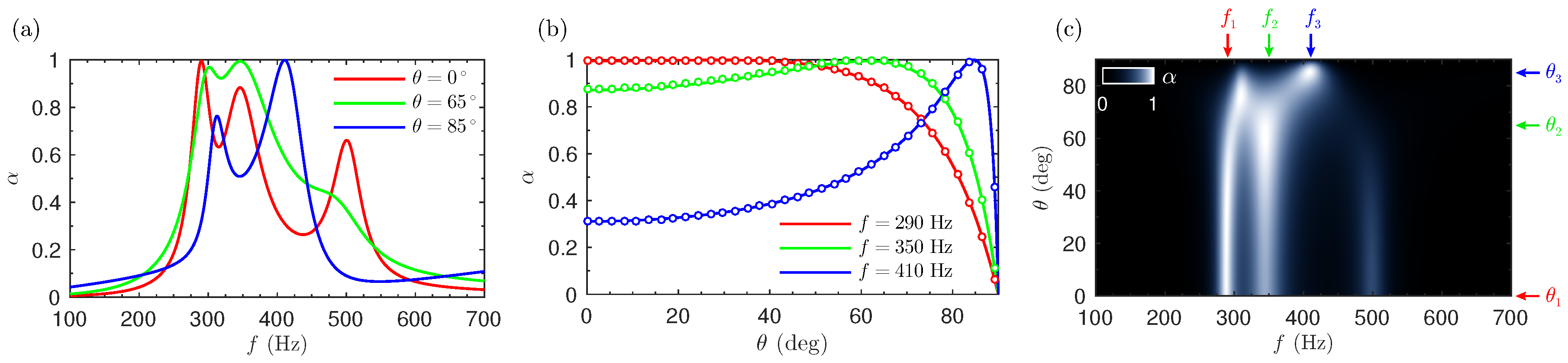
3.2. Acoustic Iridescence by Perfect Absorption

In the following, we will analyse a metamaterial using N = 3 resonators. The system was designed using an optimization method (sequential quadratic programming) [27] to obtain perfect acoustic absorption at a set of frequencies and angles: f 1 = 290 Hz and θ 1 = 0 ; f 2 = 350 Hz and θ 2 = 65 ; and f 3 = 410 Hz and θ 3 = 85 . In particular, the cost using in the optimization was ε = 1 - n = 1 N α ( θ n , f n ) / N , and the geometrical parameters of the structure were varied using only the constraint of d = 5 cm and L = c 0 / 18290 (i.e., a structure 18 times smaller than the wavelength at 290 Hz). The geometrical parameters are listed in Table A2 in the Appendix A. First, the frequency-dependent absorption produced at the different angles is shown in Figure 4a. We can see that a peak of perfect absorption is produced at the selected frequencies: f 1 = 290 Hz (red curve); f 2 = 350 Hz (green curve), and f 3 = 410 Hz (blue curve). For the selected frequencies, where perfect absorption is obtained, the absorption as a function of the incidence angle is shown in Figure 4b. Again, Equation (10) perfectly agrees with the TMM: the locally reacting system can only be critically coupled at a single angle for each selected frequency. The full map of the absorption as a function of the incidence angle and frequency is given in Figure 4c. It can be observed that when the incidence angle increases, the peaks of absorption shift in frequency, generally to higher ones, producing an acoustic iridescence effect. However, the absorption peak observed at 500 Hz for normal incidence shows a shift towards lower frequencies. In addition, it is worth noting here that the effect of the other resonators is still visible: for each angle, the absorption presents a maximum of N peaks of absorption.
As previously, the system can be analysed for complex frequencies, and the reflection coefficient is represented in the complex frequency plane, as shown in Figure 5. First, the reflection at normal incidence is presented in Figure 5a. We can see that the N = 3 zero-pole pairs are visible, one zero being exactly located on the real frequency axis at f = 290 + i 0 Hz. As the reflection vanishes, the absorption is perfect, the metamaterial being perfectly impedance matched at this particular frequency. Note that a second zero of the reflection coefficient is located at f = 300 - i 10 Hz, producing a quasi-perfect peak of absorption ( α = 0.9 ) visible in Figure 4a. The third zero is located around f = 500 + i 25 Hz, producing a third peak of absorption ( α = 0.65 ). When the incidence angle is increased, the positions of the zeros and poles move in the complex frequency plane, thus changing the physical reflection coefficient on the real frequency axis. At θ = 65 (as shown in Figure 5b), the trajectory of a zero crosses the real frequency axis at f = 350 Hz, producing perfect absorption. Note the higher frequency zero moves away from the real frequency axis, then its impact on the absorption is reduced. When the incidence angle is tilted up to θ = 85 (as shown in Figure 5c), a zero crosses the real frequency axis at f = 410 Hz, and again, perfect absorption is produced. However, it is worth noting that the trajectories of the zeros and poles interact by avoided crossing [14,28], and do not overlap. In the present case, the zero located at 410 Hz repels the zero at f = 420 + i 125 Hz, and the pole located at f = 410 - i 25 Hz repels the pole located at f = 380 - i 125 Hz, resulting in an attraction of a zero-pole pair that were not complex conjugate in the lossless case for normal incidence. As in the limit of grazing angles, the TMM model predicts that the refection is the unity, only two final solutions for the trajectories are allowed for each zero-pole pair. (i) The first option is the collapse of a zero-pole pair, as it occurs n the case of N = 1 . (ii) In the second possible solution, one zero moves towards f f r + i and a pole move towards f = f r - i . Thus, the absorption at grazing angles vanishes, as shown in Figure 5d.

3.3. Optimal Absorption in Diffuse Field

As we have shown, using a locally reacting material, perfect absorption can only be achieved at one single angle for a given frequency. However, the structure can be optimized to maximize the absorption at a broad range of angles, even when we know from Equation (10) that the absorption will be the unity only at a single angle. To use a generalized criteria, we make use of the absorption in diffuse field [20] at frequency f 0 = 300 Hz, given by
α diff ( f 0 ) = 2 0 π / 2 α ( θ , f 0 ) cos ( θ ) sin ( θ ) d θ ,
which takes into account a broad range of incidence angles, weighted to mimic diffuse field conditions. Substituting Equation (10) into (11) yields, after some algebra,
α diff , PA = 2 cos ( θ PA ) 4 + 2 cos ( θ PA ) 4 log cos ( θ PA ) - 4 log 1 + cos ( θ PA ) + sec ( θ PA / 2 ) 2 .
This expression shows the absorption in diffuse field that can be achieved using a locally reacting material presenting perfect absorption at an incidence angle θ PA .
In the following, we look for the optimal geometrical parameters of a structure that maximize α diff at a single frequency f 0 , using the cost function ε ( f 0 ) = 1 - α diff ( f 0 ) . The algorithm and constraints were the same as in the previous section. Figure 6a shows the optimized absorption using three HRs as a function of the incidence angle. The absorption in diffuse field is maximized for a structure showing perfect absorption at an angle θ PA , diff = 50.34 ° 0.28 π radians, and this leads to a maximum diffuse field absorption of α diff , MAX = 0.951 . It is worth noting here that this result is independent of the number of resonators and the kind of material; the only condition is that the structure must be a locally reacting one. Several tests were performed using 1, 2, and 3 HRs, and the results were the same. In fact, it is enough to use Equation (10) to obtain these limiting values: as Figure 6b shows, the retrieved θ PA , diff angle corresponds to the maximum of the curve given by Equation (12). In summary, the angle θ PA , diff is the the optimal to obtain the maximal value of absorption in diffuse field α diff , MAX for any locally reacting material.

4. Discussion

The current study has used a general TMM model to account for the effect of the incidence angle in the absorption. However, Equation (4) can only be applied below the Wood anomaly frequency [29,30]; i.e, when the wavenumber in the x 2 direction k 2 < 2 π / d . The present structures analysed in this work are of subwavelength dimensions; thus, this frequency is generally high: for the N = 1 metamaterial, it was f wood 6900 Hz, and for the N = 3 metamaterial, it was f wood 1800 Hz. However, the Bloch waves must be accounted for in the model if structures with larger unit-cell are considered. In addition, it has been shown that the absorption at grazing angles does not vanish; in fact, it cannot be neglected [31]: for grazing angles, the projection of the wavenumber in the x 1 is small, being the characteristic wavelength in this direction on the order of the thermal and viscous boundary layers. Thus, the proposed general model may not be accurate in the limit of grazing angles, and this should be taken into consideration for accurate predictions.

5. Conclusions

The performance of perfect absorbing metamaterials under oblique incidence has been studied analytically. In particular, we presented an ultra-thin acoustic metamaterial having perfect absorption in a broad range of angles at selected frequencies. When the incidence angle of the incoming wave is tilted, the absorption peaks shift in frequency, producing an acoustic iridescent effect due to its selective and perfect absorption at particular angles and frequencies.
We have shown that omnidirectional and perfect absorption cannot be obtained for locally reacting materials when the acoustic impedance does not depend on the incidence angle. The specific function of the absorption under oblique incidence was obtained, and this curve presents only a single maximum for each frequency. The special features of the angle-dependent absorption are illustrated using the complex frequency representation of the reflection coefficient. We show that the fact that the trajectories of the different zeros of the reflection coefficient in the complex frequency plane do not overlap prevents the observation of perfect and omnidirectional absorption in locally reacting metamaterials.
We have shown that for any locally reacting material, the maximum value of the absorption in diffuse field is 0.951, which is achieved using a material showing perfect absorption at 50.34°. This implies that to maximize the absorption performance of a material in the diffuse field, the design at normal incidence angle is not the optimal. These results can be generalized for any locally reacting material whose impedance does not depend on the incidence angle. The current study will help to guide the design of new absorbing materials under oblique incidence.

Acknowledgments

This work has been funded by the Metaudible project ANR-13-BS09-0003, co-funded by ANR and FRAE.

Author Contributions

N.J., J.P.G. and V.R. conceived, designed and performed the numerical experiments and the theory. All authors wrote and revised the paper.

Conflicts of Interest

The authors declare no conflict of interest.

Appendix A. Geometrical Parameters

The geometrical parameters for the metamaterial composed of N = 1 HR are listed in Table A1. For this structure, d = 50 mm, L = 57.2 mm, h 1 = 57.2 mm and h 2 = 24.8 mm. Thus, the structure is 24 times smaller than the wavelength at 250 Hz.
Table A1. Geometrical parameters for the resonator used in sample N = 1 .
n l n (mm) l c (mm) w n (mm) w c (mm)
10.2524.62.056.7
The geometrical parameters for the metamaterial composed of N = 3 HR are listed in Table A2. For this structure, d = 18.6 mm, L = 65.3 mm, h 1 = 15.4 mm and h 2 = 21.4 mm. Thus, the structure is 18 times smaller than the wavelength at 290 Hz.
Table A2. Geometrical parameters for the resonators used in sample N = 3 .
n l n (mm) l c (mm) w n (mm) w c (mm)
10.881.61.514.9
221.860.63.414.9
31.481.04.514.9

References

  1. Allard, J.; Atalla, N. Propagation of Sound in Porous Media: Modelling Sound Absorbing Materials 2e; John Wiley & Sons: New York, NY, USA, 2009. [Google Scholar]
  2. Olny, X.; Boutin, C. Acoustic wave propagation in double porosity media. J. Acoust. Soc. Am. 2003, 114, 73–89. [Google Scholar] [CrossRef] [PubMed]
  3. Dupont, T.; Leclaire, P.; Sicot, O.; Gong, X.L.; Panneton, R. Acoustic properties of air-saturated porous materials containing dead-end porosity. J. Appl. Phys. 2011, 110, 094903. [Google Scholar] [CrossRef]
  4. Leclaire, P.; Umnova, O.; Dupont, T.; Panneton, R. Acoustical properties of air-saturated porous material with periodically distributed dead-end poresa). J. Acoust. Soc. Am. 2015, 137, 1772–1782. [Google Scholar] [CrossRef] [PubMed]
  5. Jiménez, N.; Romero-García, V.; Cebrecos, A.; Picó, R.; Sánchez-Morcillo, V.J.; García-Raffi, L.M. Broadband quasi perfect absorption using chirped multi-layer porous materials. AIP Adv. 2016, 6, 121605. [Google Scholar] [CrossRef]
  6. Groby, J.P.; Duclos, A.; Dazel, O.; Boeckx, L.; Lauriks, W. Absorption of a rigid frame porous layer with periodic circular inclusions backed by a periodic grating. J. Acoust. Soc. Am. 2011, 129, 3035–3046. [Google Scholar] [CrossRef] [PubMed]
  7. Lagarrigue, C.; Groby, J.; Tournat, V.; Dazel, O.; Umnova, O. Absorption of sound by porous layers with embedded periodic arrays of resonant inclusions. J. Acoust. Soc. Am. 2013, 134, 4670–4680. [Google Scholar] [CrossRef] [PubMed]
  8. Boutin, C. Acoustics of porous media with inner resonators. J. Acoust. Soc. Am. 2013, 134, 4717–4729. [Google Scholar] [CrossRef] [PubMed]
  9. Groby, J.P.; Lagarrigue, C.; Brouard, B.; Dazel, O.; Tournat, V.; Nennig, B. Enhancing the absorption properties of acoustic porous plates by periodically embedding Helmholtz resonators. J. Acoust. Soc. Am. 2015, 137, 273–280. [Google Scholar] [CrossRef] [PubMed]
  10. Yang, Z.; Mei, J.; Yang, M.; Chan, N.; Sheng, P. Membrane-type acoustic metamaterial with negative dynamic mass. Phys. Rev. Lett. 2008, 101, 204301. [Google Scholar] [CrossRef] [PubMed]
  11. Mei, J.; Ma, G.; Yang, M.; Yang, Z.; Wen, W.; Sheng, P. Dark acoustic metamaterials as super absorbers for low-frequency sound. Nat. Commun. 2012, 3, 756. [Google Scholar] [CrossRef] [PubMed]
  12. Ma, G.; Yang, M.; Xiao, S.; Yang, Z.; Sheng, P. Acoustic metasurface with hybrid resonances. Nat. Mater. 2014, 13, 873–878. [Google Scholar] [CrossRef] [PubMed]
  13. Romero-García, V.; Theocharis, G.; Richoux, O.; Merkel, A.; Tournat, V.; Pagneux, V. Perfect and broadband acoustic absorption by critically coupled sub-wavelength resonators. Sci. Rep. 2016, 6, 19519. [Google Scholar] [CrossRef] [PubMed]
  14. Romero-García, V.; Theocharis, G.; Richoux, O.; Pagneux, V. Use of complex frequency plane to design broadband and sub-wavelength absorbers. J. Acoust. Soc. Am. 2016, 139, 3395–3403. [Google Scholar] [CrossRef] [PubMed]
  15. Jiménez, N.; Huang, W.; Romero-García, V.; Pagneux, V.; Groby, J.P. Ultra-thin metamaterial for perfect and quasi-omnidirectional sound absorption. Appl. Phys. Lett. 2016, 109, 121902. [Google Scholar] [CrossRef]
  16. Jiménez, N.; Romero-García, V.; Pagneux, V.; Groby, J.P. Quasiperfect absorption by subwavelength acoustic panels in transmission using accumulation of resonances due to slow sound. Phys. Rev. B 2017, 95, 014205. [Google Scholar] [CrossRef]
  17. Groby, J.P.; Huang, W.; Lardeau, A.; Aurégan, Y. The use of slow waves to design simple sound absorbing materials. J. Appl. Phys. 2015, 117, 124903. [Google Scholar] [CrossRef]
  18. Groby, J.P.; Pommier, R.; Aurégan, Y. Use of slow sound to design perfect and broadband passive sound absorbing materials. J. Acoust. Soc. Am. 2016, 139, 1660–1671. [Google Scholar] [CrossRef] [PubMed]
  19. Li, Y.; Assouar, B.M. Acoustic metasurface-based perfect absorber with deep subwavelength thickness. Appl. Phys. Lett. 2016, 108, 063502. [Google Scholar] [CrossRef]
  20. Cox, T.J.; D’Antonio, P. Acoustic Absorbers and Diffusers: Theory, Design and Application, 3rd ed.; CRC Press: Boca Raton, FL, USA, 2016. [Google Scholar]
  21. Vukusic, P. Evolutionary photonics with a twist. Science 2009, 325, 398–399. [Google Scholar] [CrossRef] [PubMed]
  22. Seago, A.E.; Brady, P.; Vigneron, J.P.; Schultz, T.D. Gold bugs and beyond: A review of iridescence and structural colour mechanisms in beetles (Coleoptera). J. R. Soc. Interface 2009, 6, S165–S184. [Google Scholar] [CrossRef] [PubMed]
  23. Cox, T.J. Acoustic iridescence. J. Acoust. Soc. Am. 2011, 129, 1165–1172. [Google Scholar] [CrossRef] [PubMed]
  24. Mechel, F.P. Formulas of Acoustics, 2nd ed.; Springer Science & Business Media: Norwell, MA, USA, 2008; pp. 316–327. [Google Scholar]
  25. Stinson, M.R. The propagation of plane sound waves in narrow and wide circular tubes, and generalization to uniform tubes of arbitrary cross-sectional shape. J. Acoust. Soc. Am. 1991, 89, 550–558. [Google Scholar] [CrossRef]
  26. Theocharis, G.; Richoux, O.; García, V.R.; Merkel, A.; Tournat, V. Limits of slow sound propagation and transparency in lossy, locally resonant periodic structures. New J. Phys. 2014, 16, 093017. [Google Scholar] [CrossRef]
  27. Powell, M.J. A fast algorithm for nonlinearly constrained optimization calculations. In Numerical Analysis; Springer: New York, NY, USA, 1978; pp. 144–157. [Google Scholar]
  28. Auregan, Y.; Pagneux, V. Slow sound in lined flow ducts. J. Acoust. Soc. Am. 2015, 138, 605–613. [Google Scholar] [CrossRef] [PubMed]
  29. Wood, R.W. Anomalous diffraction gratings. Phys. Rev. 1935, 48, 928. [Google Scholar] [CrossRef]
  30. Hessel, A.; Oliner, A. A new theory of Wood’s anomalies on optical gratings. Appl. Opt. 1965, 4, 1275–1297. [Google Scholar] [CrossRef]
  31. Burns, S.H. Normal-mode theory of enclosures with thermoviscous dissipation at the walls. J. Acoust. Soc. Am. 1978, 63, 1857–1860. [Google Scholar] [CrossRef]
Figure 1. (a) Scheme of the deep-subwavelength absorbing panel under oblique incidence, the inset shows the geometrical parameters of the Helmholtz resonators (HRs); (b) Scheme of the unit cell that composes the metamaterial.
Applsci 07 00618 g001
Figure 2. (a) Absorption of the metamaterial using N = 1 HR as a function of the frequency for incidence angles θ = 20 , 80 , 87 . 7 ; (b) Angle-dependent absorption obtained using transfer matrix method (TMM; continuous lines) and Equation (10) (circles) at frequencies f = 250 , 300 , 350 Hz; (c) Map of the absorption as a function of the frequency and incidence angle.
Applsci 07 00618 g002
Figure 3. Complex frequency representation of the reflection coefficient for the metamaterial with N = 1 HR, in logarithmic colour scale, for different angles of incidence. (a) θ = 20 ; (b) θ = 80 ; (c) θ = 87 . 7 ; (d) θ 90 . The trajectories of the poles and the zeros of the reflection coefficient as the incidence angle is increased are plotted in coloured lines, corresponding to the blueish and reddish colour bars, respectively.
Applsci 07 00618 g003
Figure 4. (a) Absorption of the metamaterial using N = 3 HRs as a function of the frequency, for incidence angles θ = 20 , 65 , 85 ; (b) Angle-dependent absorption obtained using TMM (continuous lines) and Equation (10) (circles) at frequencies f = 290 , 350 , 410 Hz; (c) Map of the absorption as a function as the frequency and incidence angle.
Applsci 07 00618 g004
Figure 5. Complex frequency representation of the reflection coefficient for the metamaterial with N = 3 HRs, in logarithmic colour scale, for different angles of incidence. (a) θ = 0 ; (b) θ = 65 ; (c) θ = 85 ; (d) θ 90 . The trajectories of the poles and the zeros of the reflection coefficient as the incidence angle is increased are plotted in coloured lines, corresponding to the blueish and reddish colour bars, respectively.
Applsci 07 00618 g005
Figure 6. (a) Angle-dependent absorption of the optimal diffuse-field absorber using TMM (continuous line) and Equation (10), at f 0 = 300 Hz; (b) Absorption in diffuse field as a function of the critical coupling angle. The maximum absorption in diffuse field is α diff , MAX = 0.952 , and is achieved for a structure critically-coupled at θ PA , diff = 50.34 ° .
Applsci 07 00618 g006

