Article

Performance Analysis of a Burst Transmission Mechanism Using Microsleep Operation for Green IEEE 802.11 WLANs †

by
Raul Palacios-Trujillo
1,
Nelson L. S. da Fonseca
1,*,
Jesus Alonso-Zarate
2 and
Fabrizio Granelli
3
1
Instituto de Computação (IC), Universidade Estadual de Campinas (UNICAMP), Av. Albert Einstein 1251, 13083-852 Campinas, SP, Brazil
2
Centre Tecnològic de Telecomunicacions de Catalunya (CTTC/CERCA), Parc Mediterrani de la Tecnologia (PMT) - Building B4, Av. Carl Friedrich Gauss 7, 08860 Castelldefels, Barcelona, Spain
3
Dipartimento di Ingegneria e Scienza dell’Informazione (DISI), Università degli Studi di Trento (UNITN), Via Sommarive 9, 38123 Povo, Trento, Italy
*
Author to whom correspondence should be addressed.
This paper is an extended version of our paper published in Palacios-Trujillo, R.; Alonso-Zarate, J.; da Fonseca, N. L. S.; Granelli, F. Maximum Achievable Energy Efficiency of TXOP Power Save Mode in IEEE 802.11ac WLANs. In Proceedings of the IEEE GLOBECOM,Washington, DC, USA, 4–8 December 2016; pp. 1–7.
Submission received: 16 June 2017 / Revised: 12 July 2017 / Accepted: 14 July 2017 / Published: 21 July 2017

Abstract

:
This paper evaluates the performance of a burst transmission mechanism using microsleep operation to support high energy efficiency in IEEE 802.11 Wireless Local Area Networks (WLANs). This mechanism is an implementation of the IEEE 802.11ac Transmission Opportunity Power Save Mode (TXOP PSM). A device using the TXOP PSM-based mechanism can switch to a low-power sleep state for the time that another device transmits a burst of data frames to a third one. This operation is called microsleep and its feasibility strongly depends on the time and energy consumption that a device incurs in the transitions from and to the sleep state. This paper accounts for the impact of these transitions in the derivation of an analytical model to calculate the energy efficiency of the TXOP PSM-based mechanism under network saturation. Results obtained show that the impact of the transition requirements on the feasibility of microsleep operation can be significant depending on the selected system parameters, although it can be reduced by using burst transmissions. When microsleep operation is feasible, the TXOP PSM-based mechanism can improve the energy efficiency of other legacy mechanisms by up to 424% under high traffic loads.

1. Introduction

Currently, the IEEE 802.11 Wireless Local Area Network (WLAN) technology, popularly known as Wi-Fi, is one of the primary means for users to connect to the Internet [1]. This has led to the proliferation of smart devices equipped with a Wi-Fi interface, such as smart appliances, wearing devices, and motor vehicles. These Internet of Things (IoT) devices can interact with each other and with other traditional devices, such as laptops, smartphones, and tablets, supporting various data-intensive Internet services (e.g., localization and navigation, online video, video file sharing, and video-conferencing) [2].
The huge amount of WLAN traffic generated can cause devices to quickly drain their batteries due to the use of Wi-Fi. In continuous operation, an active Wi-Fi interface can consume more than 70% of the total energy in a smartphone when the screen is off, and can still consume 50% when the power save mode is enabled [3,4,5].
The reduction of such high energy consumption has been enabled by the definition of two Wi-Fi certified power save mechanisms that are based on the 802.11 Power Save Mode (PSM) and the 802.11e Automatic Power Save Delivery (APSD) [6]. In PSM and APSD, an 802.11 station (STA) can enter a low-power sleep state when no transmission and reception of data are expected on a shared wireless channel. However, when there is a large amount of data to either transmit or receive, an STA remains awake for a long period of time, since it needs to wait for its turn to transmit or receive data while other STAs occupy the channel. As a result, an STA wastes energy when it receives data sent to other STAs during waiting periods (i.e., overhearing).
Such waiting periods of high energy waste in which data are sent to other STAs can be exploited to allow an STA to enter the sleep state, hence avoiding overhearing. This operation is called microsleep as it enables sleep periods in the order of tens, hundreds, or even thousands of microseconds. Microsleep was introduced in the 802.11n amendment by the Power Save Multi-Poll (PSMP) mechanism [6]. In addition, an extension of the PSMP microsleep was defined in the 802.11ac Transmission Opportunity Power Save Mode (TXOP PSM) [6]. An overview of these and other power save mechanisms including microsleep [7,8,9,10,11,12] is presented in Section 2.
Microsleep has the potential to significantly increase the energy efficiency while maintaining the desired performance. It is particularly suited under high traffic loads and in dense WLANs with a large number of STAs connected to a single Access Point (AP) or to multiple overlapping APs. Such dense WLAN scenarios occur in Smart Homes, High Efficiency WLANs (HEWs), and the IoT [13]. In addition, microsleep operation can be combined with power save mechanisms designed for low traffic loads [14], such as PSM and APSD, to provide the highest STA energy efficiency across all possible traffic loads.
Unfortunately, when existing mechanisms are employed, an STA is not able to frequently take advantage of microsleep due to the time delays and energy demands for the transitions to go to sleep and wake up. The duration and power consumption of these transitions depend on the hardware design and can be different for different STAs. For example, the transition time can be of some hundreds or few thousands of microseconds and there can be a peak of power consumption in a sleep to awake transition [15,16,17,18,19]. Moreover, microsleep is feasible only if a data transmission has longer duration than the awake and sleep transitions. In addition, the data transmission duration varies with the transmission data length and the Physical (PHY) data transmission rate employed. As the 802.11 technology continues to evolve towards higher PHY data transmission rates, data transmission times are reduced, thus making microsleep even more challenging.
In order to determine how the aforementioned system parameters can influence the feasibility of microsleep, this paper evaluates the performance of a TXOP PSM-based mechanism using burst transmissions. More specifically, this mechanism allows an STA to send one or various data frames to another STA in a single channel access attempt, while a third one can microsleep during the data exchange. An analytical model to calculate the throughput and energy efficiency of the TXOP PSM-based mechanism under network saturation is presented in this paper. By means of the proposed model and computer-based simulations, the performance of the TXOP PSM-based mechanism is evaluated and compared to those of other power save mechanisms. Results show that the performance of the TXOP PSM-based mechanism strongly depends on the system parameters, since depending on the selected system parameters microsleep may not be feasible. When microsleep operation is feasible, the TXOP PSM-based mechanism can improve the energy efficiency of PSM by up to 424% under high traffic loads.
This paper represents an extension of our previous work published in [20], in which a preliminary analysis of the energy efficiency of the TXOP PSM-based mechanism was provided. The differences between this paper and [20] are detailed in Section 2. The remainder of this paper is structured as follows. Section 2 provides a review of related work and a summary of the contributions of the paper. A brief overview of the TXOP PSM-based mechanism is then presented in Section 3. Section 4 includes the derivation of the proposed analytical model for the throughput and energy efficiency of the TXOP PSM-based mechanism under network saturation. In Section 5, a comprehensive performance evaluation of the TXOP PSM-mechanism is provided. Finally, Section 6 draws conclusions and outlines future work.

2. Related Work and Contributions

An overview of prior work concerning this paper is presented in this section. More specifically, the focus is on 802.11 power management, 802.11-based microsleep mechanisms, and analytical models for 802.11 mechanisms.

2.1. 802.11 Power Management

Two modes of power management, as well as various power save mechanisms that can be employed in each mode, are defined by the 802.11 Standard. An active mode allows an STA to receive frames at any time, i.e., the STA typically remains in a full-power awake state. In addition, a Power Save (PS) mode enables an STA to enter a low-power doze (or sleep) state for selected periods of time, thus the STA cannot always receive frames.
When operating in the PS mode, an STA can enable either the PSM, APSD, or PSMP mechanism, being PSMP the most advanced power save mechanism. This mechanism is an extension of PSM and APSD aimed at reducing the energy consumption of an STA spent in overhearing during awake periods. When PSMP is employed, an STA with buffered data at an AP, as indicated in a received beacon frame from the AP, remains awake waiting to receive a PSMP frame from the AP. The PSMP frame signals the beginning of a PSMP sequence and includes a schedule of transmission and reception times for various STAs within the PSMP sequence. When an STA is identified in a received PSMP frame, it can transmit and receive at scheduled times and sleep at the other times during a PSMP sequence (i.e., microsleep).
TXOP PSM adapts the microsleep operation of PSMP to be employed by an STA operating in the active mode, hence saving a significant amount of energy for an STA during overhearing periods. When TXOP PSM is employed, an STA can go to sleep at the beginning of data transmissions to other STAs and wake up at the end of the data transmissions. The decision to sleep is made after an STA identifies in a received frame from an AP that it is not the intended destination. The AP specifies the duration of data transmissions in transmitted frames, thus allowing the STA to determine the time to sleep.
In contrast to PSMP, TXOP PSM neither causes an AP to store data frames for an STA in the sleep state nor requires an STA to process the information included in beacon and PSMP frames. This avoids delays of frame transmissions from the AP to an STA, loss of frames at the AP, and the need of the large number of PSMP frames. In addition, TXOP PSM causes no increase in the size of beacon and PSMP frames as a function of the number of STAs, as does PSMP.

2.2. 802.11-Based Microsleep Mechanisms

Various papers [7,8,9,10,11,12] proposed mechanisms based on the microsleep operation of TXOP PSM to tackle the problem of energy consumption due to overhearing in WLANs. The mechanisms introduced in [7,8] allow an STA to switch to a low-power idle state during the transmission of a data frame sent to another STA. In addition, the mechanism in [8] allows an STA to enter the low-power idle state during the execution of the 802.11 backoff procedure employed to get access to the channel. The mechanisms proposed in [9,11] specify that an STA can go into the sleep state for the payload duration of a data frame sent to another STA. Using the mechanism defined in [10], an STA can sleep during an exchange of data frames between other STAs. Finally, the mechanism presented in [12] allows an STA to sleep during a burst transmission including various data frames sent to another STA.
The feasibility of the mechanisms in [7,8] is possible due to the very short transition time required between the low-power idle state and the transmission or the reception state (a few tens of microseconds). This transition time can be considered negligible as compared to the transmission duration of a data frame, and therefore the STAs can take advantage of microsleep. Unfortunately, the great majority of 802.11 interfaces in the market do not support such low-power state dependent on very quick transition times.
On the contrary, the low-power sleep state employed in the mechanisms in [9,10,11,12] is commonly available in most commercial 802.11 interfaces. The transitions between the awake state (either the transmission, reception, or idle state) and the sleep state can take some hundreds or few thousands of microseconds, as shown by measurements in [15,16,17,18,19]. However, few tens of microseconds for these transitions are assumed in [9,11] with no experimental validation. Likewise, no information about the transition time is given in [12]. Only in [10], the time and power consumption of the transitions are based on the aforementioned measurements. Using the measured transition times, the mechanisms introduced in [9,11,12] do not allow an STA to frequently exploit microsleep opportunities; at most an STA can enable microsleep operation for a short period of time.

2.3. Analytical Models for 802.11 Mechanisms

The Distributed Coordination Function (DCF) is the fundamental channel access mechanism defined by the 802.11 Standard. Extensive work has been undertaken to evaluate the performance of this mechanism. More specifically, a two dimensional Markov chain model to compute the throughput of DCF under network saturation was proposed in [21], being the most widely-used analytical model to evaluate the performance of DCF. Refinements of this basic model were then introduced in various papers to account for details of specific operation of DCF, such as finite retransmission attempts [22,23], backoff freezing [24], and other operation details. In addition, some papers analyze the throughput and delay of other DCF extensions, such as DCF with frame bursting [25] and the 802.11e Enhanced Distributed Channel Access (EDCA) with its Transmission Opportunity (TXOP) mechanism [26,27].
While the aforementioned papers mainly concentrate on the throughput and delay performance, other papers, such as [28,29], analyze the energy consumption of DCF. These papers show that DCF causes high energy consumption in an STA during idle and overhearing periods. In [30], the focus is on PSM as an extension of DCF to save energy, as defined by the 802.11 Standard. More specifically, such paper provides an analytical model to compute the throughput, delay, and power consumption of PSM. In addition, an energy efficiency analysis of a TXOP PSM-based mechanism using burst transmissions is presented in [20]. Results obtained from such analysis show that only when microsleep operation is feasible can the TXOP PSM-based mechanism achieve higher energy efficiency as compared to DCF and PSM under high traffic loads. Such results also show that the feasibility of microsleep operation strongly depends on the system parameters used, such as the transmission data length, the PHY data transmission rate, and the transition time between awake and sleep states.

2.4. Contributions of the Paper

The core contribution of this paper is the analytical evaluation of the throughput and energy efficiency of a burst transmission mechanism using microsleep operation under network saturation conditions. In line with [12,20], this mechanism represents a possible implementation of IEEE 802.11ac TXOP PSM on the top of 802.11 DCF using burst transmissions [25] (similar to 802.11e EDCA TXOP). Basically, when the TXOP PSM-based mechanism is employed, an STA can send a burst of data frames to another STA, while a third one can microsleep during the data exchange. A more detailed description of the TXOP PSM-based mechanism is provided in the following section.
The analytical model proposed in this paper builds on the Markov chain model introduced in [21] and extended in [24] to compute the DCF throughput under saturation conditions. Contrary to the papers [12,28,29,30], this paper considers the requirements of the awake and sleep transitions in the derivation of the proposed model, since these transitions can compromise the feasibility of microsleep operation. As compared to the analysis proposed in [20], the analysis introduced in this paper concentrates on both the throughput and energy efficiency of the TXOP PSM-based mechanism under saturation conditions. In addition, a comprehensive derivation of the energy efficiency depending on the feasibility of microsleep operation is provided in the proposed analysis. Moreover, a comprehensive performance evaluation of the proposed TXOP PSM-based mechanism as a function of various system parameters is illustrated and discussed in this paper, not considered in [20].
The proposed analysis allows the determination of the critical system parameters that influence the performance of the TXOP PSM-based mechanism and other microsleep mechanisms such as those in [7,8,9,10,11,12]. Computer-based simulations are used to validate the proposed analysis. Results presented in this paper contribute to the development of advanced microsleep mechanisms for the next-generation WLANs.

3. TXOP PSM-Based Mechanism Using Burst Transmissions

This section describes the operation of the TXOP PSM-based mechanism in an infrastructure Basic Service Set (BSS) consisting of a finite and fixed number n of STAs associated to an AP. The STAs of the BSS and the AP exchange data with each other using a shared wireless channel. In addition, all the STAs can listen to all the transmissions between the STAs and the AP.
In order to transmit data, the AP and the STAs access the channel following contention-based rules according to the 802.11 DCF specification. More specifically, they wait for the channel to be idle during a DCF Interframe Space (DIFS) period, or an Extended Interframe Space (EIFS) period after the end of a collision. The time that follows either a DIFS or an EIFS period is divided into slots. The AP and the STAs are allowed to initiate transmission only at the beginning of each slot time. Before transmitting, they also wait for a backoff time after a period in which the channel is busy, a consecutive transmission, or a failed transmission. The length of this period is initially obtained as a random number of slot times from a Contention Window (CW) of size ranging from a minimum size ( C W m i n ) to a maximum size ( C W m a x ), called backoff counter. When the channel is sensed idle during a slot time, the AP and the STAs decrement their backoff counters by one, and transmit when their backoff counters are equal to zero. Therefore, their actual backoff times can differ depending on the channel occupancy.
As soon as the AP or an STA gets access to the channel, it takes the role of the source STA in the current transmission cycle. The STA addressed by the source STA becomes the destination STA and all other STAs behave as listening STAs, neither transmitting nor receiving frames. The source STA can send a burst of α data frames to the destination STA, including the expected transmission duration in the MAC header of the transmitted data frames. Following the successful reception of each data frame, the destination STA responds with a positive Acknowledgment (ACK) frame after a Short Interframe Space (SIFS) period. In addition, the source STA can send a Request to Send (RTS) frame to the destination STA and wait for a Clear to Send (CTS) frame response after a SIFS period, prior to the actual transmission of data. Note that the transmission duration can also be attached to the RTS and CTS frames.
When the listening STAs receive a frame addressed to the destination STA, they initiate the virtual carrier sense procedure defined by the DCF specification. More specifically, each listening STA maintains a Network Allocation Vector (NAV) specifying the channel occupancy time. This information is taken from the duration field contained in the MAC header of overheard RTS, CTS, data, and ACK frames. The listening STAs do not attempt to transmit for the time indicated by their NAVs and enable a microsleep operation until the NAV expiration. They can sleep as long as their NAVs are longer than the time they take in the transitions to go to sleep and wake up. If this condition is fulfilled, the time they can actually sleep is calculated as the time difference between their NAVs and their transition times between awake and sleep states.
Allowing the source STA to send multiple data frames ( α > 1 ) to the destination STA can facilitate microsleep operation due to longer transmission times, as compared to when only one frame transmission ( α = 1 ) is performed. So as to increase the chances for multiple frame transmissions, the AP and the STAs can aggregate data frames during a certain time before transmission; this period of time is called holding time. If, prior to expiration of the holding time, they already have α data frames with the same destination address, they can immediately attempt to transmit these frames.
An operation example of the TXOP PSM-based mechanism is shown in Figure 1. STA 1 and the AP contend for access to the channel to send various data frames to each other. After a DIFS period and a random backoff time, first STA 1 and then the AP get access to the channel. Either STA 1 or the AP, i.e., the source STA, initiates an RTS/CTS handshake with the AP or STA 1 respectively, i.e., the destination STA, and then performs a burst transmission of various data frames. Meanwhile, other STAs, i.e., the listening STAs, set their NAVs to the duration of the burst transmission taken from the duration field of the RTS frame and go to sleep. They wake up when their NAVs expire at the end of the burst transmission.
It is worth noting that the operation of the TXOP PSM-based mechanism can also support frame aggregation and block ACK in a similar way to how the TXOP PSM-based mechanism operates using burst transmissions.

4. Analytical Model

This section introduces an analytical model to calculate the throughput and energy efficiency of the TXOP PSM-based mechanism under network saturation. This analysis builds on the Markov chain model presented in [21] and its extension [24] to evaluate the throughput of 802.11 DCF under network saturation.

4.1. Assumptions and Notations

The network operation considered in the proposed analysis is a fully-connected single-hop network consisting of an AP and n STAs, as described in the previous section. This network setting implies that no hidden terminal exists. In addition, it is assumed that the AP and the STAs operate in saturation conditions, i.e., they always have data frames to be sent. The AP and the STAs employ the TXOP PSM-based mechanism with the RTS/CTS handshake enabled to contend for access to the channel, and α data frames can be sent in each successful channel access attempt. Data frames of the same size are assumed. The channel is assumed to be error free and no capture effect is considered.
The Markov chain analysis presented in [21] is the basis of the analytical model proposed in this paper. The reader is assumed to be familiar with such analysis; a brief description of the derivation in [21] is provided next. In the analysis, ideal channel conditions as well as a finite and fixed number n of contending STAs in saturation conditions are assumed. The analytical model proposed therein is enabled by the fact that each single STA sees the events occurring on the channel according to a discrete, though not uniform, slotted time scale. In such model, the slot time can refer to either a constant value σ when the channel is sensed idle or a variable time interval when the channel is sensed busy. The key approximation in the model is that the probability p of collision of a transmitted frame is constant and independent of how many times the frame has been retransmitted. Based on the conditional collision probability p, the probability τ of an STA transmitting in a randomly chosen slot time is determined. Then, by studying the events that can occur within a generic slot time, the throughput of DCF under network saturation, hereafter referred to as saturation throughput, is obtained as a function of τ . In [24], the throughput expression in [21] is then refined to properly account for the backoff freezing operation in the DCF specification.

4.2. Throughput

The saturation throughput S is defined in [21] as the ratio of the average amount of payload bits successfully transmitted in a slot time to the average length of a slot time. S can be expressed as [21,24]:
S = P t r P s E [ P ] 1 P t r σ + P t r P s T s + P t r 1 P s T c .
With probability P t r = 1 1 τ n + 1 there is at least one transmission in a slot time, given n STAs and the AP contending on the channel. Similarly, with probability P s = n + 1 τ 1 τ n / P t r an attempt to transmit a frame is successful. In addition, E [ P ] = E [ P ] / 1 B 0 is the average amount of payload bits transmitted in a successful transmission, where B 0 = 1 / W is the probability that a successfully transmitting STA can get access to the channel in the first slot time immediately after a DIFS period and W = C W m i n + 1 . The probability that a slot time is empty is given by 1 P t r , and σ is the duration of an empty slot time. P t r P s , is the probability that a successful transmission occurs in a slot time, being T s = ( T s / 1 B 0 ) + σ the average duration of a successful transmission. With probability P t r ( 1 P s ) , a collision occurs in a slot time, and T c = T c + σ is the average duration of a collision.
It is worth noting that the throughput Expression (1) is obtained without specifying the access mechanism employed. In order to compute the throughput for a given DCF access mechanism it is necessary to determine the values of T s and T c .
T s represents the duration of a successful transmission. For the TXOP PSM-based mechanism, this duration includes a DIFS period, an RTS transmission, a CTS transmission, α data transmissions, α ACK transmissions, 1 + 2 α SIFS periods, and 2 1 + α propagation delays, as shown in Figure 1. Therefore, T s is given by
T s = T R T S + T C T S + α T D A T A + T A C K + T D I F S + 1 + 2 α T S I F S + 2 1 + α δ ,
where T D I F S and T S I F S are the duration of the DIFS and SIFS periods, respectively, and δ is the propagation delay. T R T S , T C T S , T D A T A , and T A C K are the times required to transmit the RTS, CTS, data, and ACK frames, respectively. In addition, α is the number of data frames that the source STA is allowed to transmit to the destination STA in a successful channel access attempt.
T c represents the duration of a collision. Either if DCF or the TXOP PSM-based mechanism is employed, this duration comprises the RTS transmission plus the propagation delay and an EIFS period, thus T c = T R T S + δ + T E I F S .
In order to account for burst transmissions, β is defined as the number of data frames transmitted in a successful channel access attempt. Hence, the numerator in (1) is rewritten as β P t r P s E [ P ] . Since each successful channel access attempt using the TXOP PSM-based mechanism includes the transmission of α data frames, β = α .

4.3. Energy Efficiency

The energy efficiency under network saturation η , hereafter referred to as saturation energy efficiency, is defined herein as the ratio of the average number of payload bits successfully transmitted in a slot time to the average amount of energy consumed in a slot time. The saturation energy efficiency is derived following a similar rationale to that used in the derivation of the saturation throughput in [21,24]. Using (1) and the derivation above to compute S, η can be expressed as
η = β P t r P s E [ P ] 1 P t r E σ + P t r P s E s + P t r 1 P s E c ,
where E σ is the energy consumed during an empty slot time. In addition, E s and E c are the average energy consumed during a successful transmission and a collision, respectively.
Since n STAs and the AP consume energy for being idle during an empty slot time σ , E σ is given by
E σ = σ n + 1 ρ i ,
where ρ i is the power consumption corresponding to the idle state.
Using T s , E s can be derived as
E s = E s 1 B 0 + σ n + 1 ρ i ,
where E s is given by the sum of various energy consumption components, being E t , E r , E i , E s w , and E s l the energy consumed in the transmission, reception, idle, switch, and sleep states, respectively.
The expression of E s depends on whether the listening STAs are able to sleep during a successful transmission or not. To determine this, the microsleep period during a successful transmission T s l is computed as the time difference between the total transmission duration available for sleeping and the transition time between awake and sleep states. More specifically, when the TXOP PSM-based mechanism is employed this duration comprises all that occurs following the RTS transmission plus the propagation delay. As shown in Figure 1, this duration includes the CTS transmission, α data transmissions, α ACK transmissions, 1 + 2 α SIFS periods, and 1 + 2 α propagation delays. Being T i s l and T s l i the time required to switch from idle (i.e., awake) to sleep and from sleep to idle, respectively, T s l is obtained as
T s l = T C T S + α 2 T D A T A + T A C K + 1 + 2 α T S I F S + δ T i s l + T s l i .
If T s l is longer than zero ( T s l > 0 ), the listening STAs are able to sleep during a successful transmission. For the TXOP PSM-based mechanism, this scenario is illustrated in Figure 1.
Let E s T s l > 0 be the energy consumed by all the STAs and the AP in a successful transmission when T s l > 0 . The various energy consumption components of E s T s l > 0 are obtained as follows.
In order to derive the transmission energy consumption E t T s l > 0 it is assumed that the source STA consumes energy to perform the RTS and α data transmissions to the destination STA. In addition, the destination STA consumes energy to perform the CTS and α ACK transmissions to the source STA. Being ρ t the power consumption corresponding to the transmission state, E t T s l > 0 is expressed as
E t T s l > 0 = T R T S + T C T S + α T D A T A + T A C K ρ t .
To compute the reception energy consumption E r T s l > 0 , it is considered that the source STA consumes energy to receive the CTS and α ACK transmissions from the destination STA. Then, the destination STA consumes energy to receive the RTS and α data transmissions from the source STA. In addition, the rest of STAs (i.e., n 1 ) consume energy to overhear the RTS and CTS transmissions only, as they can sleep for the remainder of the data transmission. Let s be the number of active STAs, being s = 1 (apart from the AP). Being ρ r the power consumed in the reception state, E r T s l > 0 is given by
E r T s l > 0 = T R T S + T C T S n + α 2 T D A T A + T A C K s ρ r .
To calculate the idle energy consumption E i T s l > 0 , it is assumed that n STAs and the AP consume energy to listen to the channel during a DIFS period. Both the source and destination STAs also consume energy to listen to the channel for the duration of 1 + 2 α SIFS periods and 1 + 2 α propagation delays. In addition, the n s listening STAs consume energy to listen to the channel during the propagation delay following the RTS transmission. Thus, E i T s l > 0 is derived as
E i T s l > 0 = T D I F S + T S I F S + 2 δ n + 1 + 1 + 2 α T S I F S + 3 α δ s + 1 ρ i .
In order to determine the switch energy consumption E s w T s l > 0 , it is considered that the n s listening STAs consume energy during the transitions from idle to sleep T i s l and from sleep to idle T s l i . Being ρ s l i and ρ i s l the power consumption for switching from sleep to idle and from idle to sleep, respectively, E s w T s l > 0 is computed as
E s w T s l > 0 = T i s l ρ i s l + T s l i ρ s l i n s .
To derive the sleep energy consumption E s l T s l > 0 , it is assumed that the n s listening STAs consume energy to sleep during the microsleep period T s l . Hence, E s l T s l > 0 is calculated as
E s l T s l > 0 = T s l n s ρ s l ,
where ρ s l is the power consumed in the sleep state.
Based on the above, E s T s l > 0 can be obtained as
E s T s l > 0 = E t T s l > 0 + E r T s l > 0 + E i T s l > 0 + E s w T s l > 0 + E s l T s l > 0 .
Otherwise, if T s l is equal to or shorter than zero ( T s l 0 ), the listening STAs cannot sleep and remain awake consuming energy for listening to the whole data exchange. Let E s T s l 0 be the energy consumed by all the STAs and the AP in a successful transmission when T s l 0 . The various energy consumption components of E s T s l 0 for the TXOP PSM-based mechanism are computed as follows.
The transmission energy consumption E t T s l 0 is given by (7), since both the source and destination STAs consume energy to transmit their respective frames.
To compute the reception energy consumption E r T s l 0 , it is considered that the source STA consumes energy to receive the CTS and α ACK transmissions from the destination STA. In addition, the destination STA consumes energy to receive the RTS and α data transmissions from the source STA. The n 1 listening STAs consume energy to overhear the RTS, CTS, α data, and α ACK transmissions. This yields
E r T s l 0 = T R T S + T C T S + α T D A T A + T A C K n ρ r .
To calculate the idle energy consumption E i T s l 0 , it is assumed that n STAs and the AP consume energy for being idle during a DIFS period, 1 + 2 α SIFS periods, and 2 1 + α propagation delays interleaving the transmissions. Thus, E i T s l 0 is expressed as
E i T s l 0 = T D I F S + 1 + 2 α T S I F S + 2 1 + α δ n + 1 ρ i .
The listening STAs consume no energy for switching between idle and sleep states and for sleeping, since they remain awake during the whole data transfer.
Therefore, E s T s l 0 can be obtained as
E s T s l 0 = E t T s l 0 + E r T s l 0 + E i T s l 0 .
Using T c , E c can be written as
E c = E c + σ n + 1 ρ i ,
where n STAs and the AP consume energy for listening to the channel during an empty slot time σ following the end of a collision.
E c accounts for the energy consumed during a collision. Being E [ k ] the average number of transmitting STAs involved in a collision, E [ k ] STAs consume energy to send the RTS frames colliding. Meanwhile, the rest of listening STAs (i.e., n + 1 E [ k ] ) consume energy to listen to the collision of the RTS frames. In addition, n STAs and the AP consume energy for listening to the channel during the propagation delay following the RTS transmissions and during an EIFS period after the end of the collision. Hence, E c is given by
E c = T R T S E [ k ] ρ t + n + 1 E [ k ] ρ r + T E I F S + δ n + 1 ρ i .
The value of E [ k ] is obtained by analyzing all the possible cases that two or more STAs up to n + 1 STAs (including the AP) transmit in a randomly chosen slot time. Let i be the number of STAs involved in a collision and i ( 2 , n + 1 ) . The probability of i STAs causing a collision is the probability that exactly i STAs access the channel in the same slot time, given that a collision occurs. For each value of i, there is a number of combinations that i STAs out of n + 1 STAs take part in a collision. Therefore, E [ k ] is derived as
E [ k ] = i = 2 n + 1 n + 1 i τ i 1 τ n + 1 i P t r 1 P s .

5. Performance Evaluation

The performance of the TXOP PSM-based mechanism, hereafter referred to as TXOP PSM for simplicity, is evaluated in this section. Results were obtained from the analytical model proposed in the previous section and computer-based simulations conducted in an event-driven simulation program written in the Python programming language. Evaluation of various system parameters such as the traffic load, data frame length, PHY data transmission rate, number of STAs, and amount of α data frames sent in a burst transmission is considered. In addition, performance comparison between TXOP PSM and different reference mechanisms is presented.

5.1. Reference Mechanisms and Simulation Description

This paper considers two main reference mechanisms, namely IEEE 802.11 DCF and PSM, to compare their performance with that of TXOP PSM. Such mechanisms, as well as TXOP PSM, are assumed to enable the RTS/CTS handshake and can operate either with or without burst transmissions, i.e., α > 1 or α = 1 . DCF and PSM with α = 1 are considered according to the IEEE 802.11 legacy specification in [6]. DCF with α > 1 (similar to 802.11e EDCA TXOP) operates following the definition in [25], which is also used in TXOP PSM. PSM with α > 1 (similar to 802.11e APSD) is based on the operation of DCF with α > 1 in [25], and is described in more detail below. Finally, TXOP PSM with α = 1 accounts for the operation of the mechanisms in [7,8,9,11], whereas TXOP PSM with α > 1 operates as the mechanism in [12].
A Python simulation program that implements all the operation rules of the aforementioned mechanisms using the network operation and assumptions described in the previous sections was developed. The main motivations for using a custom simulator rather than other available network simulators (e.g., OPNET and ns-3) are the faster execution of the simulations and the fact that advanced sleep mode operations are not yet implemented in other existing simulators. The simulator used in this paper supports all required functionalities to validate the proposed model and to assess how selected system parameters influence the performance of the evaluated mechanisms.
More specifically, the simulated network operation considers an AP and n STAs generating data frames of the same size by following a Poisson process. All the STAs generate data frames addressed to the AP at an equal rate λ 1 , whereas the rate at which the AP generates data frames is λ 2 = n λ 1 . The destination of each data frame sent by the AP is chosen at random among all the STAs with equal probability 1 / n . This setting provides balanced bidirectional data flows between the AP and each STA on average. In addition, the AP and the STAs enable a holding time during which they can aggregate up to α data frames with the same destination address before attempting to transmit. This holding time allows the creation of more opportunities for multiple data transmissions in each channel access attempt.
The simulated operation of PSM using the holding time and α > 1 is described as follows. The AP broadcasts a fixed-size beacon frame at each beacon interval, after waiting for the channel to be idle during a Point Coordination Function Interframe Space (PIFS) period. All the STAs wake up to receive the beacon frame and determine if there are buffered data frames for them at the AP. The beacon frame includes buffer status information only for STAs that have α buffered data frames at the AP or a buffered data frame with an expired holding time. When an STA has buffered data at the AP, it transmits a PS-Poll frame to the AP and the AP replies with an ACK frame. The AP then delivers up to α buffered data frames to an STA, in accordance with the order of received PS-Poll frames, as soon as it gets access to the channel. In addition, an STA can wake up to transmit data only after the expiration of the holding time or whenever there are α data frames ready to be transmitted.
The simulated time for each simulation experiment was set to 15 seconds and each simulation experiment was repeated 10 times. The average values of the collected simulation data were employed to compute the simulation results for each parameter set. In addition, confidence intervals of 95% were calculated. Since the width of these confidence intervals is at most 2% of the mean values, they are omitted in the figures for the sake of visualization.

5.2. System Parameters

The system parameters used to obtain the analytical and simulation results correspond to those defined by the 802.11 Extended Rate PHY (ERP) specification with the Orthogonal Frequency Division Multiplexing (OFDM) modulation. This PHY mode can be enabled in either an 802.11b/g interface or an 802.11n/ac interface enabling a single antenna for communications. Such PHY mode provides transmission rates and frame transmission times that allow us to clearly show the significant influence of the awake and sleep transitions on the feasibility of the microsleep operation of TXOP PSM.
More specifically, the available transmission rates of this PHY mode are 6, 9, 12, 18, 24, 36, 48, and 54 Mbps, with their respective Number of Data Bits Per OFDM Symbol ( N D B P S ) 24, 36, 48, 72, 96, 144, 192, and 216. While any of these transmission rates can be used to transmit RTS, PS-Poll (only in PSM), and data frames, only the basic rates 6, 12, and 24 Mbps are allowed for the transmission of CTS and ACK frames. The selection of 6, 12, or 24 Mbps for the CTS and ACK transmissions depends on whether the RTS, PS-Poll, and data frames are sent at 6 or 9, 12 or 18, or 24, 36, 48, or 54 Mbps, respectively. In addition, the beacon frames are broadcast at the lowest basic rate of 6 Mbps. The specification of these basic rate selection rules is provided by the 802.11 Standard [6].
The time to transmit each frame type x using the ERP-OFDM PHY mode is computed as
T x = T p r e + T s i g + T s y m L s e r v + 8 L x + L t a i l N D B P S + T s i g E x ,
where all the variables and their values are included in Table 1. More specifically, L x denotes the Medium Access Control (MAC) frame length. For a MAC data frame, this length comprises the frame body or MAC Service Data Unit (MSDU) along with a MAC header and a Frame Check Sequence (FCS). For example, using an MSDU of 1500 bytes and RTS/data and CTS/ACK transmission rates of 54 and 24 Mbps, respectively, the values of T R T S , T C T S , T D A T A , and T A C K are 30, 34, 254, and 34 μ s, respectively. It is worth noting that the propagation delay following a frame transmission ( δ ) was neglected in the performance evaluation of the mechanisms.
In addition, other variables presented in Table 1 are calculated as follows. The PIFS period is obtained by [6] as T P I F S = T S I F S + σ and the DIFS period as T D I F S = T S I F S + 2 σ . The EIFS period is computed by [6] as T E I F S = T D I F S + T S I F S + T A C K (6 Mbps). The holding time was set to 100 ms to run simulations since this duration enables the highest performance for all the evaluated mechanisms with α > 1 . The values of power consumption in transmission, reception, idle, and sleep states were obtained from [15,16,17,18,19]. The time and power consumption of the awake and sleep transitions were considered according to the results presented in [15,16,17,18,19]: (i) T i s l is similar to T s l i , (ii) ρ i s l is significantly lower than ρ s l , and iii) ρ s l i is significantly higher than ρ i . Consequently, as shown in 
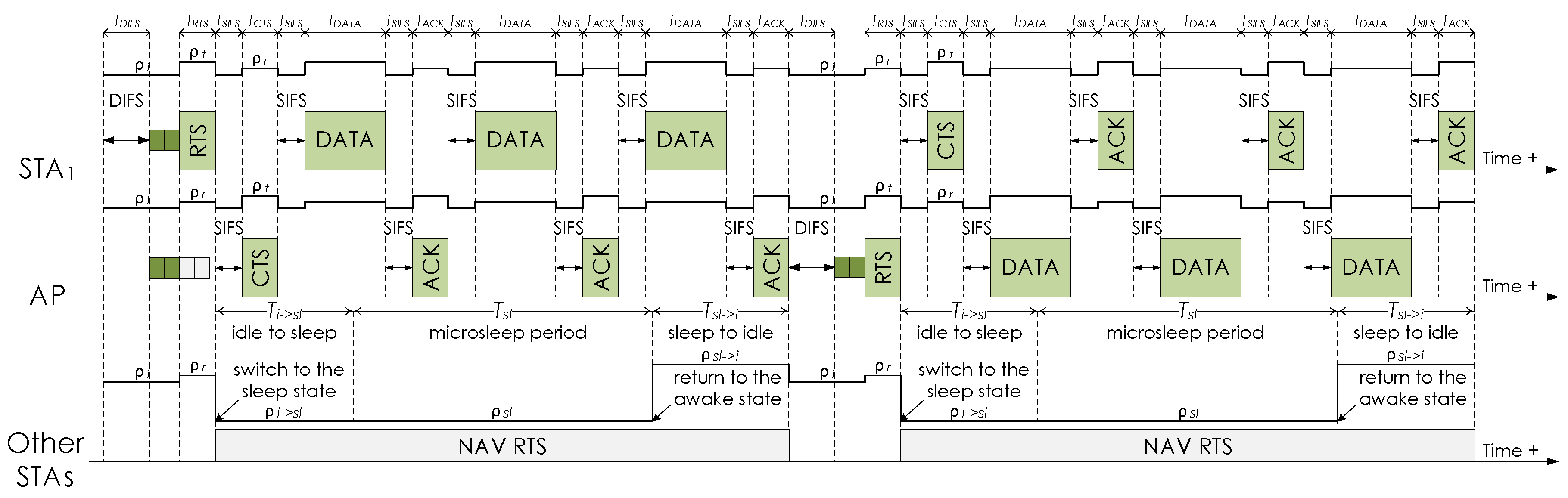
Figure 1 for the energy consumption of other STAs, it is assumed that: (i) T i s l is equal to T s l i (the value was obtained from [15,16,17,18,19]), (ii) ρ i s l is equal to ρ s l , and (iii) ρ s l i is modeled as γ ρ i , where γ is defined as the coefficient of power consumption during the transition from sleep to idle and γ > 1 ( γ = 1.5 was used according to [15,16,17,18,19]).
Unless otherwise specified, an infrastructure BSS consisting of an AP and 20 STAs, a 1500-byte MSDU length, and PHY control and data transmission rates of 24 and 54 Mbps were considered to derive the analytical and simulation results.

5.3. Results

All the figures shown in this section include solid lines referring to the analytical results and markers related to the simulation results. It is also worth noting that the results of energy efficiency of the evaluated mechanisms as a function of the traffic load, MSDU length, and PHY data transmission rate were presented in [20].
(1) Impact of the Traffic Load
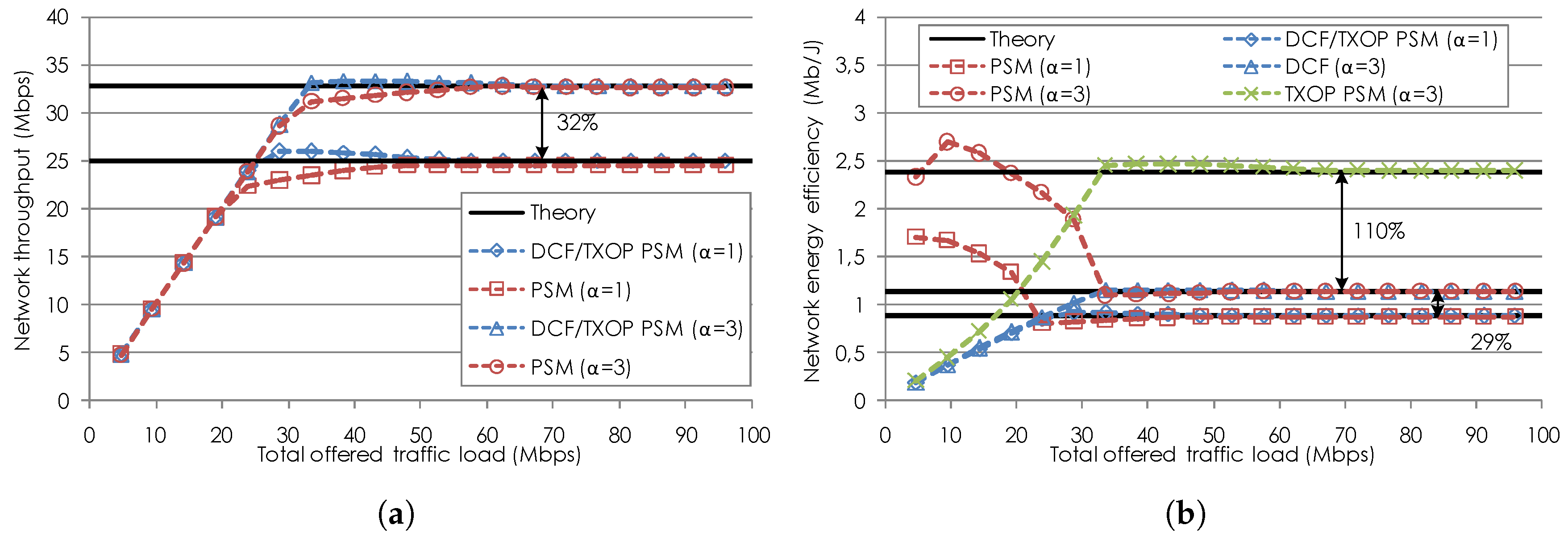
The network throughput and energy efficiency of the evaluated mechanisms with α = 1 and α = 3 rounds of data transmissions as a function of the total offered traffic load are shown in Figure 2a and Figure 2b, respectively. As it can be seen in Figure 2a, the throughput of the mechanisms linearly increases as the traffic load increases. Each mechanism achieves a maximum stable value of the throughput when the network is in saturation. The saturation throughput of the mechanisms using α = 3 is higher than that achieved by the mechanisms when α = 1 is employed. The reason is that the AP and the STAs can send up to three data frames in each channel access opportunity, hence enabling the reduction of the overall channel access overhead. In addition, it can be seen that the throughput of DCF and TXOP PSM is the same across all traffic loads whereas PSM attains lower throughput than DCF and TXOP PSM under high traffic loads. This is because PSM, in contrast to TXOP PSM, modifies the operation of the STAs to receive data frames from the AP in order to improve energy efficiency. It is also worth noting that DCF, PSM, and TXOP PSM with α = 3 produce a throughput improvement of up to 32% when compared to those with α = 1 .
In Figure 2b, results show the energy efficiency for each mechanism. More specifically, when DCF is employed, the network energy efficiency has a similar shape to that of the throughput, and under saturation conditions it increases up to 29% for DCF using α = 3 as compared to DCF with α = 1 . This is due to the fact that the energy consumption of the AP and the STAs does not increase significantly with higher traffic loads, while the increase in the amount of transmitted data frames is significant.
As opposed to DCF, the energy efficiency of PSM is the highest under low traffic loads since the STAs can sleep for a long period of time. The energy efficiency of PSM is significantly reduced under high traffic loads, close to the energy efficiency value of DCF. This occurs because the majority of the STAs remain awake most of the time to transmit and receive data. Note that the energy efficiency of PSM with α = 3 is reduced more slowly than that of PSM with α = 1 as the traffic load increases. The reason is that the STAs do not wake up until there are at least three data frames to transmit or their holding times expire. For this reason, the energy efficiency of PSM using α = 3 , being always above that of PSM using α = 1 , increases a little and then decreases under low to medium traffic loads.
In such range of traffic loads and when α = 3 is employed, TXOP PSM attains higher energy efficiency than DCF but lower energy efficiency than PSM, as shown in Figure 2b. However, under high traffic loads, TXOP PSM improves the energy efficiency of both DCF and PSM by up to 110%. This occurs because the AP and the STAs normally send two or three data frames together in a single channel access attempt, hence enabling listening STAs to sleep and save energy. It is also worth noting that TXOP PSM with α = 1 cannot improve the energy efficiency of DCF under high traffic loads. The reason is that, considering the selected system parameters, no STA can sleep during the transmission of a single data frame. This means that the duration of data transmissions are shorter than the transition times of the STAs between awake and sleep states.
Figure 2a,b show that the analytical results corresponding to the saturation network throughput and energy efficiency of all the evaluated mechanisms match the simulation results. In addition, this observation can be made for the rest of the figures presented next.
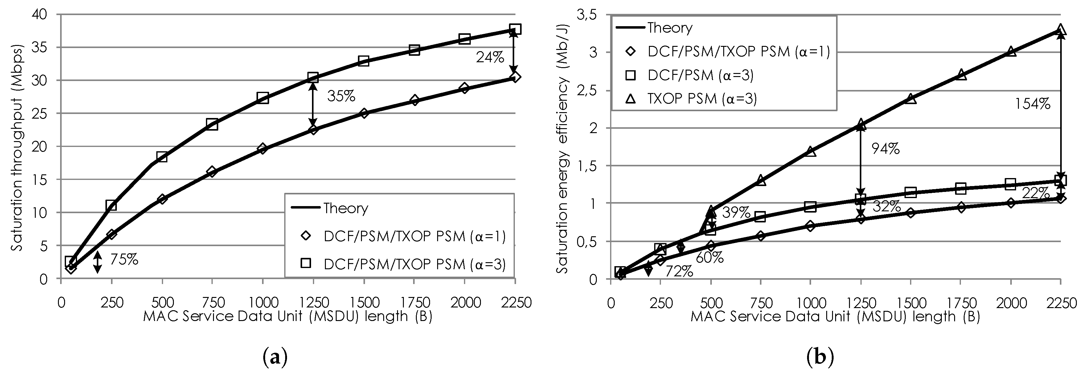
(2) Impact of the MSDU Length
The saturation throughput and energy efficiency of the evaluated mechanisms with α = 1 and α = 3 as a function of the MSDU length ranging from 50 bytes to 2250 bytes are shown in Figure 3a and Figure 3b, respectively. Since DCF and PSM show similar saturation performance, the saturation throughput and energy efficiency of DCF and those of PSM are shown together with a single line and marker for the sake of visualization. This is also used for TXOP PSM with α = 1 since TXOP PSM performs the same as DCF, with the exception of the saturation energy efficiency of TXOP PSM when α = 3 is employed. In what follows, the terms throughput and energy efficiency will be used to refer to the saturation throughput and the saturation energy efficiency, respectively.
As it can be seen in Figure 3a, the throughput of the evaluated mechanisms increases as the MSDU length increases since each transmitted data frame includes more information. As in the throughput as a function of the traffic load, DCF, PSM, and TXOP PSM with α = 3 outperform these using α = 1 for all the MSDU lengths. The throughput improvement ranges from 75% to 24% as the MSDU length increases up to 2250 bytes. This reduction of the throughput improvement is caused by the fact that the longer data frames are the more the data transmission time increases during channel access, thus reducing the influence of the lower channel access overhead enabled by using α = 3 . For this reason, the increase in energy efficiency for DCF and PSM using α = 3 as compared to these with α = 1 also ranges from 72% to 22% as the MSDU length increases, as shown in Figure 3b .
It can also be seen in Figure 3b that TXOP PSM with α = 1 improves the energy efficiency of DCF and PSM for all the MSDU lengths. The reason is that the STAs are not able to microsleep during data transmissions. In addition, TXOP PSM using α = 3 achieves energy efficiency increasing at the same rate as that of DCF and PSM until the MSDU length is long enough to enable microsleep operation. This refers to an MSDU length that provides a non-zero microsleep period ( T s l ). For TXOP PSM using α = 3 , this requirement is fulfilled when the MSDU length is above 449 bytes. When the MSDU length increases from such value to 2250 bytes, the energy efficiency of TXOP PSM using α = 3 is significantly higher than that of DCF and PSM with an improvement ranging from 39% to 154%. This is due to longer microsleep periods as the MSDU length increases, thus allowing the STAs to sleep for a longer period and save more energy.
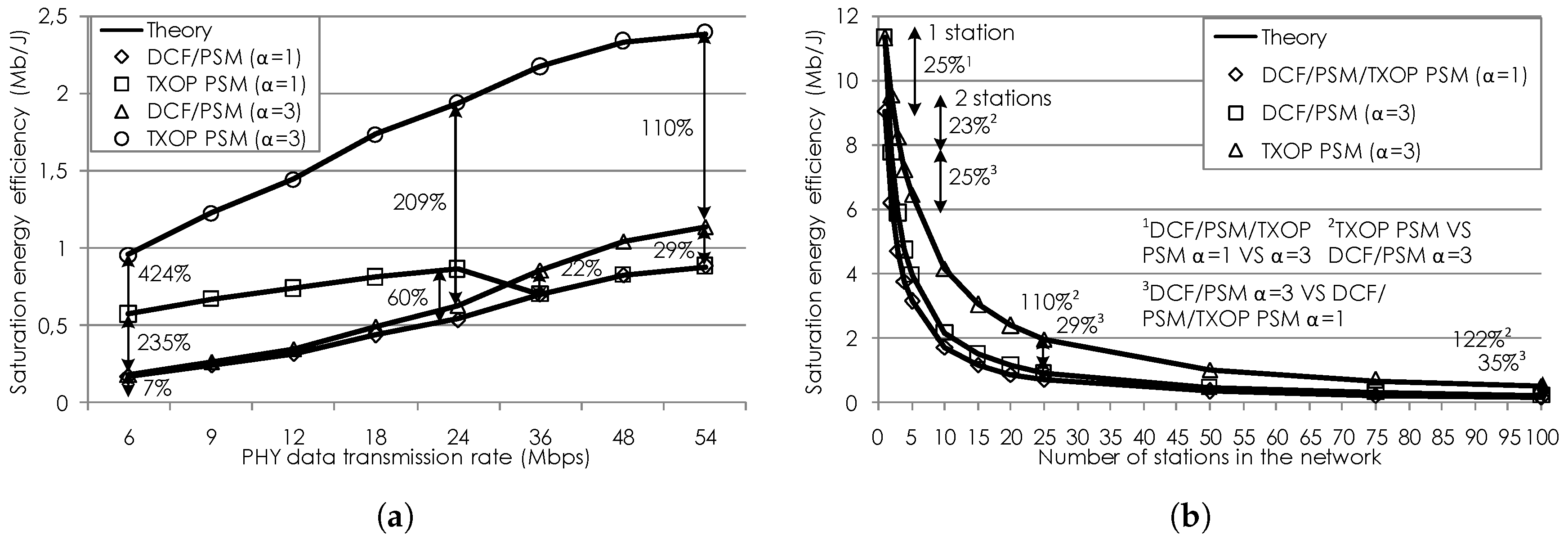
(3) Impact of the PHY Data Transmission Rate
Figure 4 shows the saturation energy efficiency of the evaluated mechanisms as a function of the PHY data transmission rate and the number of STAs. More specifically, Figure 4a focuses on the PHY data transmission rate ranging from 6 Mbps to 54 Mbps. Results for the energy efficiency of DCF and PSM are plotted together with a single line and marker. On the contrary, the energy efficiency of TXOP PSM is shown with a different line and marker since its behavior is significantly different from those of DCF and PSM. It is also worth noting that the results of the saturation throughput as a function of the PHY data transmission rate are not shown due to their similarities to those presented for the MSDU length. A throughput improvement ranging from 7% to 32% for DCF, PSM, and TXOP PSM using α = 3 as compared to these with α = 1 is achieved as the PHY data transmission rate increases from 6 Mbps to 54 Mbps.
Figure 4a shows that all the mechanisms attain higher energy efficiency with higher PHY data transmission rates. This is due to the fact that the time to send a data frame becomes shorter, hence resulting in higher efficiency of data transmission. In addition, it can be seen that DCF and PSM using α = 3 achieve an increase in energy efficiency from 7% to 29% as compared to DCF and PSM with α = 1 when the PHY data transmission rate increases from 6 Mbps to 54 Mbps.
As it can be seen in Figure 4a, TXOP PSM with α = 1 significantly improves the energy efficiency of DCF and PSM for PHY data transmission rates lower than 36 Mbps. The highest increase of 235% in energy efficiency is achieved for the lowest PHY data transmission rate of 6 Mbps. Such increase in energy efficiency decreases from 235% to 60% for higher PHY data transmission rates up to 24 Mbps. The reason is that the transmission duration is shorter or longer depending on whether the PHY data transmission rates increases or decreases, respectively. Shorter data transmission times decrease the time that the STAs can sleep whereas longer transmission times increase the microsleep period. For higher PHY data transmission rates ranging from 36 Mbps to 54 Mbps, TXOP PSM with α = 1 performs as DCF and PSM. This occurs because these PHY data transmission rates do not produce data transmission times enabling microsleep operation based on the awake and sleep transition times of the STAs.
In addition, it can be seen in Figure 4a that TXOP PSM using α = 3 can allow the STAs to sleep for all the PHY data transmission rates, achieving the highest energy efficiency value. The improvement ranging from 424% to 110% for TXOP PSM when compared to DCF and PSM is obtained when the PHY data transmission rate increases from 6 Mbps to 54 Mbps.
(4) Impact of the Number of STAs
Figure 4b shows the saturation energy efficiency of the evaluated mechanisms with α = 1 and α = 3 as a function of the number of STAs up to 100 STAs. The energy efficiency of DCF and PSM as well as that of TXOP PSM with α = 1 are shown by a single line and marker. A different line and marker are used to plot the energy efficiency of TXOP PSM with α = 3 . In addition, in line with the PHY data transmission rate, results for the saturation throughput as a function of the number of STAs are omitted. DCF, PSM, and TXOP PSM using α = 3 achieve a high stable throughput improvement that ranges from 28% to 39% when compared to DCF, PSM, and TXOP PSM with α = 1 as the number of STAs increases up to 100 STAs.
As shown in Figure 4b, the energy efficiency of all the mechanisms decreases as the number of STAs in the network increases. The reason is that more STAs consume energy for overhearing frames sent to the AP or other STAs. More specifically, DCF and PSM with α = 3 attain an increase in energy efficiency that ranges from 25% to 35% as compared to when they employ α = 1 with larger numbers of STAs up to 100 STAs. This is due to the reduction of the overall channel access overheard enabled by the use of α = 3 .
In addition, it can be seen in Figure 4b that the energy efficiency of TXOP PSM using α = 1 is the same as that of DCF and PSM. However, TXOP PSM with α = 3 achieves the highest energy efficiency for numbers of STAs above 1 STA as compared to DCF and PSM. No improvement over DCF and PSM is obtained when the network is composed of the AP and an STA, since this STA can never go to sleep. For larger numbers of STAs from 2 STAs to 100 STAs, TXOP PSM provides a significant increase in energy efficiency between 23% and 122%, since more STAs can sleep and consequently save energy.
(5) Impact of the Number of α -Rounds of Data Transmissions
The saturation throughput and energy efficiency of the evaluated mechanisms as a function of the number of α -rounds of data transmissions from α = 1 to α = 10 are presented in Figure 5a and Figure 5b, respectively. As it can be seen in Figure 5a, the throughput of the mechanisms increases as the value of α increases, since more data frames can be sent in each channel access attempt. The maximum throughput is achieved for α = 10 , although the throughput increases slightly after α = 5 . This occurs because the contribution of the reduced channel access overhead to the total transmission time becomes marginal as compared to that of the data transmission time. For this reason, the maximum throughput improvement of DCF, PSM, and TXOP PSM between α = 1 and α = 10 is up to 48%. In addition, an increase of up to 44% in energy efficiency for DCF and PSM between α = 1 and α = 10 can be seen in Figure 5b.
As it can also be seen in Figure 5b, the energy efficiency of TXOP PSM significantly increases between α = 1 and α = 10 and as compared to DCF and PSM. The increase of TXOP PSM with α = 10 when compared to TXOP PSM using α = 1 is up to 483%. The energy efficiency of TXOP PSM can also increase by up to 306% from α = 1 to α = 10 when compared to DCF and PSM. The reason for these results is that, as more data frames can be sent in a single channel access attempt, the STAs can sleep for a longer period and save more energy.

6. Conclusions

An analytical model to compute the throughput and energy efficiency of a burst transmission mechanism using microsleep operation under network saturation was presented in this paper. This mechanism represents a simple implementation of the IEEE 802.11ac TXOP PSM mechanism on the top of the fundamental IEEE 802.11 DCF mechanism using burst transmissions. When the TXOP PSM-based mechanism is employed, a device can send a burst of α data frames to another device while a third device can microsleep during the data exchange. Such device enabling microsleep operation spends a given time and consumes power in the transitions to enter and exit a low-power sleep state. The proposed model takes into account the influence of these transitions, since the requirements of these transitions can compromise the feasibility of microsleep operation.
A comprehensive performance evaluation of the TXOP PSM-based mechanism, called TXOP PSM for simplicity, was provided using the proposed model and computer-based simulations. The performance of TXOP PSM was compared to those of DCF and PSM using burst transmissions as a function of various system parameters. The results presented in this paper show a strong dependence of TXOP PSM performance on the system parameters. More specifically, TXOP PSM using α = 3 improves the throughput of TXOP PSM with α = 1 (no burst transmission) by up to 75% in scenarios with heavy traffic, small frames, high PHY rates, and many devices. When α = 3 is employed, TXOP PSM also enables microsleep operation and increases the energy efficiency of DCF and PSM by up to 424% in scenarios with heavy traffic, large frames, low PHY rates, and many devices. In addition, the throughput and energy efficiency of TXOP PSM can increase up to 48% and 483%, respectively, as the value of α increases from α = 1 to α = 10 .
In future work, the authors plan to evaluate the performance of TXOP PSM using frame aggregation and block acknowledgment in scenarios including different traffic classes and multiple shared channels. Moreover, the authors aim at testing the mechanism in real-life environments by using programmable wireless platforms.

Acknowledgments

This work was funded by the FP7-GREENET European research project under grant PITN-GA-2010-264759, the CNPq Brazilian research agency, and Motorola Mobility Brazil.

Author Contributions

Raul Palacios-Trujillo conceived and designed the work in collaboration with Nelson L. S. da Fonseca, Jesus Alonso-Zarate, and Fabrizio Granelli. He also performed the experiments, analyzed the data, and wrote the paper. Nelson L. S. da Fonseca, Jesus Alonso-Zarate, and Fabrizio Granelli substantially contributed to the critical revision of the paper.

Conflicts of Interest

The authors declare no conflict of interest. The funding sponsors had no role in the design of the study; in the collection, analyses, or interpretation of data; in the writing of the manuscript, and in the decision to publish the results.

References

  1. Wi-Fi Alliance 6 for ’16 Wi-Fi Predictions. 2016. Available online: http://www.wi-fi.org/beacon/wi-fi-alliance/wi-fi-alliance-6-for-16-wi-fi-predictions (accessed on 14 July 2017).
  2. The Zettabyte Era–Trends and Analysis. White Paper. 2016. Available online: http://www.cisco.com/c/en/us/solutions/collateral/service-provider/visual-networking-index-vni/vni-hyperconnectivity-wp.html (accessed on 14 July 2017).
  3. Pering, T.; Agarwal, Y.; Gupta, R.; Want, R. CoolSpots: Reducing the Power Consumption of Wireless Mobile Devices with Multiple Radio Interfaces. In Proceedings of the 4th international conference on Mobile Systems, Applications and Services (ACM MobiSys), Uppsala, Sweden, 19–22 June 2006; pp. 220–232. [Google Scholar]
  4. Perrucci, G.; Fitzek, F.; Widmer, J. Survey on Energy Consumption Entities on the Smartphone Platform. In Proceedings of the 73rd IEEE Vehicular Technology Conference, VTC Spring, Yokohama, Japan, 15–18 May 2011; pp. 1–6. [Google Scholar]
  5. Jin, T.; Noubir, G.; Sheng, B. WiZi-Cloud: Application-transparent Dual ZigBee-WiFi Radios for Low Power Internet Access. In Proceedings of the IEEE INFOCOM, Shanghai, China, 10–15 April 2011; pp. 1593–1601. [Google Scholar]
  6. IEEE Standard for Information Technology. Telecommunications and Information Exchange between Systems Local and Metropolitan Area Networks—Specific Requirements—Part 11: Wireless LAN Medium Access Control (MAC) and Physical Layer (PHY) Specifications; IEEE Std 802.11-2016; IEEE: Piscataway, NY, USA, 2016; pp. 1–3534. [Google Scholar]
  7. Biswas, S.; Datta, S. Reducing Overhearing Energy in 802.11 Networks by Low-power Interface Idling. In Proceedings of the IEEE International Conference on Performance, Computing, and Communications, Phoenix, AZ, USA, 15–17 April 2004; pp. 695–700. [Google Scholar]
  8. Baiamonte, V.; Chiasserini, C.F. Saving Energy during Channel Contention in 802.11 WLANs. Mob. Netw. Appl. 2006, 11, 287–296. [Google Scholar] [CrossRef]
  9. Balaji, B.; Tamma, B.R.; Manoj, B.S. A Novel Power Saving Strategy for Greening IEEE 802.11 Based Wireless Networks. In Proceedings of the IEEE Global Telecommunications Conference, GLOBECOM, Miami, FL, USA, 6–10 December 2010; pp. 1–5. [Google Scholar]
  10. Palacios, R.; Larbaa, E.M.B.; Alonso-Zarate, J.; Granelli, F. Performance Analysis of Energy-Efficient MAC Protocols using Bidirectional Transmissions and Sleep Periods in IEEE 802.11 WLANs. In Proceedings of the IEEE Global Telecommunications Conference, GLOBECOM, Austin, TX, USA; 2014; pp. 1269–1275. [Google Scholar]
  11. Sudarshan, S.; Prasad, R.; Kumar, A.; Bhatia, R.; Tamma, B.R. Ubersleep: An Innovative Mechanism to Save Energy in IEEE 802.11 based WLANs. In Proceedings of the IEEE International Conference on Electronics, Computing and Communication Technologies, CONECCT, Bangalore, India, 6–7 January 2014; pp. 1–6. [Google Scholar]
  12. Omori, K.; Tanigawa, Y.; Tode, H. A Study on Power Saving using RTS/CTS Handshake and Burst Transmission in Wireless LAN. In Proceedings of the 10th Asia-Pacific Symposium on Information and Telecommunication Technologies, APSITT, Colombo, Sri Lanka, 4–7 August 2015; pp. 1–3. [Google Scholar]
  13. Omar, H.A.; Abboud, K.; Cheng, N.; Malekshan, K.R.; Gamage, A.T.; Zhuang, W. A Survey on High Efficiency Wireless Local Area Networks: Next Generation WiFi. IEEE Commun. Surv. Tutor. 2016, 18, 2315–2344. [Google Scholar] [CrossRef]
  14. Tsao, S.L.; Huang, C.H. Review: A Survey of Energy Efficient MAC Protocols for IEEE 802.11 WLAN. ACM Comput. Commun. 2011, 34, 54–67. [Google Scholar] [CrossRef]
  15. Kamerman, A.; Monteban, L. WaveLAN-II: A High-Performance Wireless LAN for the Unlicensed Band. Bell Labs Tech. J. 1997, 2, 118–133. [Google Scholar] [CrossRef]
  16. Havinga, P.J.M.; Smit, G.J.M. Energy-efficient TDMA medium access control protocol scheduling. In Proceedings of the Asian International Mobile Computing Conference, AMOC, Penang, Malaysia, 1–3 November 2000; pp. 1–10. [Google Scholar]
  17. Jung, E.S.; Vaidya, N.H. An Energy Efficient MAC Protocol for Wireless LANs. In Proceedings of the IEEE Twenty-First Annual Joint Conference of the IEEE Computer and Communications Societies (INFOCOM), New York, NY, USA, 23–27 June 2002; Volume 3, pp. 1756–1764. [Google Scholar]
  18. Sengul, C.; Harris, A.F.; Kravets, R. Reconsidering Power Management. In Proceedings of the Fourth International Conference on Broadband Communications, Networks and Systems, BROADNETS, Raleigh, NC, USA, 10–14 September 2007; pp. 799–808. [Google Scholar]
  19. Jang, K.Y.; Hao, S.; Sheth, A.; Govindan, R. Snooze: Energy Management in 802.11n WLANs. In Proceedings of the ACM CoNEXT, Tokyo, Japan, 6–9 December 2011; pp. 1–12. [Google Scholar]
  20. Palacios-Trujillo, R.; Alonso-Zarate, J.; da Fonseca, N.L.S.; Granelli, F. Maximum Achievable Energy Efficiency of TXOP Power Save Mode in IEEE 802.11ac WLANs. In Proceedings of the IEEE Global Communications Conference, GLOBECOM, Washington, DC, USA, 1–8 December 2016; pp. 1–7. [Google Scholar]
  21. Bianchi, G. Performance Analysis of the IEEE 802.11 Distributed Coordination Function. IEEE J. Sel. Areas Commun. 2000, 18, 535–547. [Google Scholar] [CrossRef]
  22. Wu, H.; Peng, Y.; Long, K.; Cheng, S.; Ma, J. Performance of Reliable Transport Protocol over IEEE 802.11 Wireless LAN: Analysis and Enhancement. In Proceedings of the Twenty-First Annual Joint Conference of the IEEE Computer and Communications Societies, INFOCOM, New York, NY, USA, 23–27 June 2002; Volume 2, pp. 599–607. [Google Scholar]
  23. Chatzimisios, P.; Vitsas, V.; Boucouvalas, A.C. Throughput and Delay Analysis of IEEE 802.11 Protocol. In Proceedings of the EEE 5th International Workshop on Networked Appliances, IWNA, Liverpool, UK, 30–31 October 2002; pp. 168–174. [Google Scholar]
  24. Bianchi, G.; Tinnirello, I. Remarks on IEEE 802.11 DCF Performance Analysis. IEEE Commun. Lett. 2005, 9, 765–767. [Google Scholar] [CrossRef]
  25. Vitsas, V.; Chatzimisios, P.; Boucouvalas, A.C.; Raptis, P.; Paparrizos, K.; Kleftouris, D. Enhancing Performance of the IEEE 802.11 Distributed Coordination Function via Packet Bursting. In Proceedings of the IEEE Global Telecommunications Conference Workshops, GLOBECOM, Dallas, TX, USA, 29 November–3 December 2004; pp. 245–252. [Google Scholar]
  26. Abu-Sharkh, O.M.F.; Tewfik, A.H. Toward Accurate Modeling of the IEEE 802.11e EDCA under Finite Load and Error-Prone Channel. IEEE Trans. Wirel. Commun. 2008, 7, 2560–2570. [Google Scholar] [CrossRef]
  27. Tinnirello, I.; Choi, S. Temporal Fairness Provisioning in Multi-Rate Contention-Based 802.11e WLANs. In Proceedings of the Sixth IEEE International Symposium on a World of Wireless Mobile and Multimedia Networks, WoWMoM, Taormina-Giardini Naxos, Italy, 16 June 2005; pp. 220–230. [Google Scholar]
  28. Carvalho, M.M.; Margi, C.B.; Obraczka, K.; Garcia-Luna-Aceves, J.J. Modeling Energy Consumption in Single-Hop IEEE 802.11 Ad Hoc Networks. In Proceedings of the 13th International Conference on Computer Communications and Networks, ICCCN, Chicago, IL, USA, 11–13 October 2004; pp. 367–372. [Google Scholar]
  29. Ergen, M.; Varaiya, P. Decomposition of Energy Consumption in IEEE 802.11. In Proceedings of the IEEE International Conference on Communications, ICC, Glasgow, UK, 24–28 June 2007; pp. 403–408. [Google Scholar]
  30. Swain, P.; Chakraborty, S.; Nandi, S.; Bhaduri, P. Performance Modeling and Analysis of IEEE 802.11 IBSS PSM in Different Traffic Conditions. IEEE Trans. Mob. Comput. 2015, 14, 1644–1658. [Google Scholar] [CrossRef]
Figure 1. Operation example of the TXOP PSM-based mechanism when the RTS/CTS handshake is enabled. First STA 1 and then the AP send a burst of data frames to each other, while other STAs sleep based on the duration carried in the RTS frame. The energy profiles of STA 1 , the AP, and other STAs during transmission, reception (or overhearing), idle, and sleep periods are shown in the figure. The notations of time and power consumption included in the figure are used in the analytical model presented in Section 4.
Applsci 07 00744 g001
Figure 2. Network throughput and energy efficiency of the evaluated mechanisms with α = 1 and α = 3 rounds of data transmissions as a function of the traffic load. (a) Throughput. (b) Energy efficiency.
Applsci 07 00744 g002
Figure 3. Saturation throughput and energy efficiency of the evaluated mechanisms with α = 1 and α = 3 rounds of data transmissions as a function of the MSDU length. (a) Saturation throughput. (b) Saturation energy efficiency.
Applsci 07 00744 g003
Figure 4. Saturation energy efficiency of the evaluated mechanisms with α = 1 and α = 3 rounds of data transmissions as a function of the PHY data transmission rate and the number of STAs. (a) PHY data transmission rate. (b) Number of STAs.
Applsci 07 00744 g004
Figure 5. Saturation throughput and energy efficiency of the evaluated mechanisms as a function the number of α -rounds of data transmissions. (a) Saturation throughput. (b) Saturation energy efficiency.
Applsci 07 00744 g005
Table 1. System Parameters.
ParameterValue
Slot time ( σ )9 μ s
SIFS period ( T S I F S )10 μ s
PIFS period ( T P I F S )19 μ s
DIFS period ( T D I F S )28 μ s
EIFS period ( T E I F S )88 μ s
Beacon interval100 ms
Minimum CW size ( C W m i n )15
Maximum CW size ( C W m a x )1023
Preamble time ( T p r e )16 μ s
Signal time ( T s i g )4 μ s
OFDM symbol period ( T s y m )4 μ s
Signal extension period ( T s i g E x )6 μ s
Service bits ( L s e r v )16 b
Tail bits ( L t a i l )6 b
Length of a beacon ( L B )20 B
Length of RTS ( L R T S )20 B
Length of PS-Poll ( L P S P o l l )20 B
Length of CTS ( L C T S )14 B
Length of ACK ( L A C K )14 B
Length of the MAC header ( L M A C h d r )30 B
Length of FCS ( L F C S )4 B
Transition time from idle to sleep ( T i s l )250 μ s
Transition time from sleep to idle ( T s l i )250 μ s
Transmission power consumption ( ρ t )1.65 W
Reception power consumption ( ρ r )1.4 W
Idle power consumption ( ρ i )1.15 W
Sleep power consumption ( ρ s l )0.045 W
Idle to sleep transition power consumption ( ρ i s l )0.045 W
Sleep to idle transition power consumption ( ρ s l i )1.725 W
Holding time100 ms

