Irradiation Induced Defect Clustering in Zircaloy-2

Department of Mechanical and Materials Engineering, Queen’s University, Kingston, ON K7L 3N6, Canada
*
Author to whom correspondence should be addressed.
Appl. Sci. 2017, 7(8), 854; https://0-doi-org.brum.beds.ac.uk/10.3390/app7080854
Submission received: 6 July 2017
/
Revised: 6 August 2017
/
Accepted: 7 August 2017
/
Published: 18 August 2017
(This article belongs to the Special Issue Radiation Effects of Materials with Laser, Ion Beam and Rays)
Abstract
:Featured Application
The data and results will be helpful to evaluate the radiation damages in fuel cladding or calandria tube of nuclear power plants.
Abstract
The effect of irradiation temperature and alloying elements on defect clustering behaviour directly from the cascade collapse in Zircaloy-2 is examined. The in-situ ioWn irradiation technique was employed to study the formation of <a>-type dislocation loops by Kr ion irradiation at 573 K and 773 K, while the dependence of dislocation loop formationon the presence of alloying elements was investigated by comparing with the defect microstructures of pure Zr irradiated under similar conditions. The experimentally observed temperature dependence of defect clustering was further investigated using molecular dynamics (MD) simulations near the experimental irradiation temperatures. We particularly concentrate on yield and morphology of small defect clusters formed directly from cascade collapse at very low ion doses. Smaller loop size and higher defect yield (DY) in Zircaloy-2 as compared to pure Zr suggests that the presence of the major alloying element Sn increases the number of nucleation sites for the defect clusters but suppresses the point defect recombination. MD simulations at 600 and 800 K revealed that the production of both vacancy and interstitial clusters drops significantly with an increase of irradiation temperature, which is reflected in experimentally collected DY data.
1. Introduction
Owing to their low neutron absorption, good mechanical strength, and corrosion resistance, Zr alloys are widely used in nuclear power reactors. However, neutron damage of zirconium-based core reactor components leads to in-reactor deformation such as irradiation growth, hardening, loss of ductility, and localised plastic instability [1]. The fundamental mechanism of these degradations is neutron induced atomic displacement in alloys. One of most important damage microstructures is called a “dislocation loop”, which evolves from atomic displacement cascades [2]. The study of the dislocation loop evolution of Zr alloys under irradiation is of active interest. In Zr alloys, prismatic (<a>-type) dislocation loops are the basic and most well-known component of radiation damage structures and are observed in a wide range of irradiation temperatures (80–500 °C) [2]. These loops are visible at lower to higher neutron doses, with densities saturating at relatively low doses, and have been extensively studied by neutron, charged particle irradiation, and MD simulations [2,3,4,5,6,7,8]. It has been reported that the point-defect clusters formed in Zircaloy-2 at temperatures between 250 and 400 °C and for irradiation doses lower than 5 × 1025 nm−2 (E > 1 MeV), which can be observed by using transmission electron microscopy (TEM) (>2 nm), and consist of perfect dislocation loops, either of vacancy or interstitial nature, with Burgers vector of , lying in the prismatic planes () and () planes with typical diameters from 5 to 20 nm, depending on the fluence and irradiation temperature [9,10]. Neutron irradiated microstructures reveal that the loop dimensions are smaller in Zr alloys compared to pure Zr irradiated under similar conditions (1 × 1024 n/m2, E > 1 MeV, 400 °C) [11]. A number of studies on pure Zr and various Zr alloys of different compositions have been conducted in the past, either by using charged ion irradiation or fast neutron irradiation. The early study conducted by Buckley and Manthorpe [12] on pure Zr, Zircaloy, and Zr-Nb alloys focused on the temperature and solute concentration dependencies of prismatic loops using high voltage electron microscope (HVEM). It was concluded that the presence of solutes increases the density and decreases the growth rate of loops generated during electron irradiation by an order of magnitude, although in this case, the damage mechanism is significantly different from neutron irradiation [11]. Similarly, Hellio et al. [13] conducted in-situ 1 MeV electron irradiation experiments on pure Zr, Zr-1% Nb, and Zircaloy-4, at higher irradiation temperature (>400 °C). Loop size increased with increasing irradiation temperature, whereas higher prismatic loop densities in the presence of alloying elements (O, Nb, Sn) were attributed to the preferential nucleation of loops at the impurity atoms. Due to the nature of displacement cascades produced in Zr, irradiation by heavy ions is a reasonable simulation of neutron irradiation in reactors and has been the tool for experimental studies in several different materials.
A Ni ion bombardment study of Zircaloy-2 with a wide range of variables (O content, 300–600 °C, 0.65–87 dpa) was conducted by Adamson et al. [14], where ex-situ ion irradiated microstructures were investigated and compared to neutron-irradiated microstructure. The dominant defects were difficult to individually identify due to the defect strain field overlap and presence of small hydrides induced during electro-polishing. Higher irradiation temperature seemed to cause an alignment of defects with the trace of the basal plane, which was attributed to the interaction of defect clusters with the solutes and to self-climb and/or prismatic glide. It was concluded that Ni ion bombardment at 300 and 400 °C is a reasonable simulation of neutron damage. However, no damage structures were found after irradiation at 600 °C. An in situ heavy ion irradiation investigation was conducted by Idrees et al. [15] on pure Zr in order to observe prismatic loops experimentally, particularly at lower doses close to their nucleation threshold as a function of dose and irradiation temperature. It was reported that the small defect clusters (~2 nm) are perfect dislocation loops, with Burgers vector . The size of these loops increases and defect densities decrease with an increase of temperature.
Similarly, a trend of increased loop size and decreased defect yield (DY) with an increase of irradiation temperature was observed by several authors after neutron and ion irradiations [14,16,17]. In an early study on neutron-irradiated Zr and Zr-based alloys by Gilbert et al. [17], it was found that dislocation loops are not formed at higher temperature in Zr and Zr alloys, which indicates that at higher temperatures, vacancies and interstitials instead recombine after the cascade collapse. It was also found that the dislocation loops’ size increases and DY decreases with an increase of irradiation temperature until the damage structure declines at 773 K. It was pointed out that in these neutron irradiated samples, there is an absence of radiation damage at 773 K, which is 0.42 of the absolute melting temperature of α-Zr. Ion irradiation studies on pure Zr show similar effects on loop sizes and densities with increasing irradiation temperature, except there was still a formation of large dislocation loops at 773 K [15]. The presence of these loops at 773 K may indicate decreased V-SIA (vacancy/self-interstitial atom) recombination possibilities leaving a high concentration of point defects, which then cluster in the form of dislocation loops. We can expect that this would be affected by the presence of suitable alloying elements.
It is vital to know and understand the effects of alloying element on the point defect clustering behaviour at higher temperatures. The effect of temperature on the production of point defects in displacement cascades and their clustering during the life time of cascades have been studied using Molecular Dynamic computer modeling (MD). MD simulations have been carried out in alpha Zr at lower temperatures (100 K) [18,19,20,21] and at intermediate temperature (600 K) [20]. Gao et al. [20] reported that the number of vacancies and interstitials deceases with increasing temperature for a given cascade energy, which has been attributed to the longer thermal spike time. These interstitials and vacancies form perfect dislocation loops with Burgers vector b =. Contrarily, Voskoboinikov et al. [21] have reported that the number of Frenkel pairs produced in Zr are independent of irradiation temperature within a temperature range of 100–600 K, which was attributed to the stability of both vacancy and self-interstitial atom (SIA) clusters at all irradiation temperatures. The study of defect distribution at temperatures higher than 600 K is important in order to understand the defect clustering behaviour and dislocation loop formation at higher temperatures as well as for a given Primary Knock-on Atom (PKA) energy. Initial nucleation of <a> loops in the form of small defect clusters was reported after MD computation, but has not been extensively studied experimentally. Ion irradiation can produce a high PKA energy for the study of prismatic loop formation at low doses, similar to the doses at which prismatic loops are seen during neutron irradiation, for comparison with the results of MD simulations. In addition, in situ ion irradiation within TEM coupled with a high energy irradiation facility such as a tandem accelerator allows direct observation of internal microstructure of materials while being irradiated [22].
The present study aims to investigate the nucleation of prismatic loops at low doses and their dependence on the irradiation temperature and impurity content of materials. MD simulations at different temperatures are used to investigate the role of temperature in defect formation, whereas comparison of TEM results in Zircaloy-2 and pure Zr is used to discern the role of alloying elements.
2. Materials and Methods
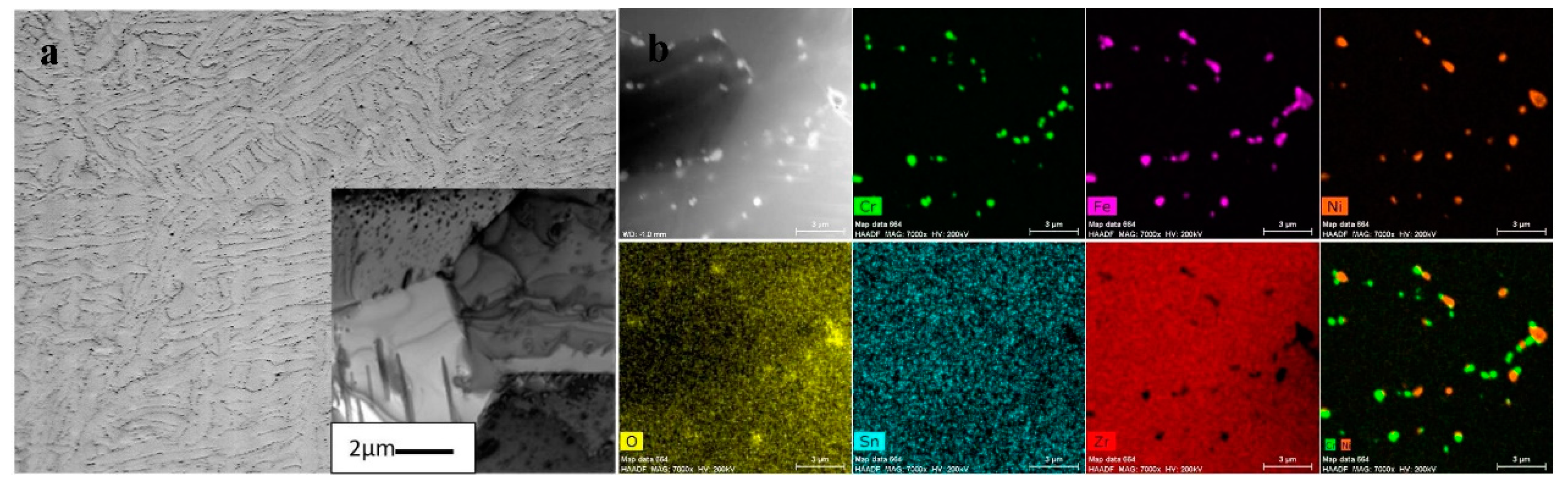
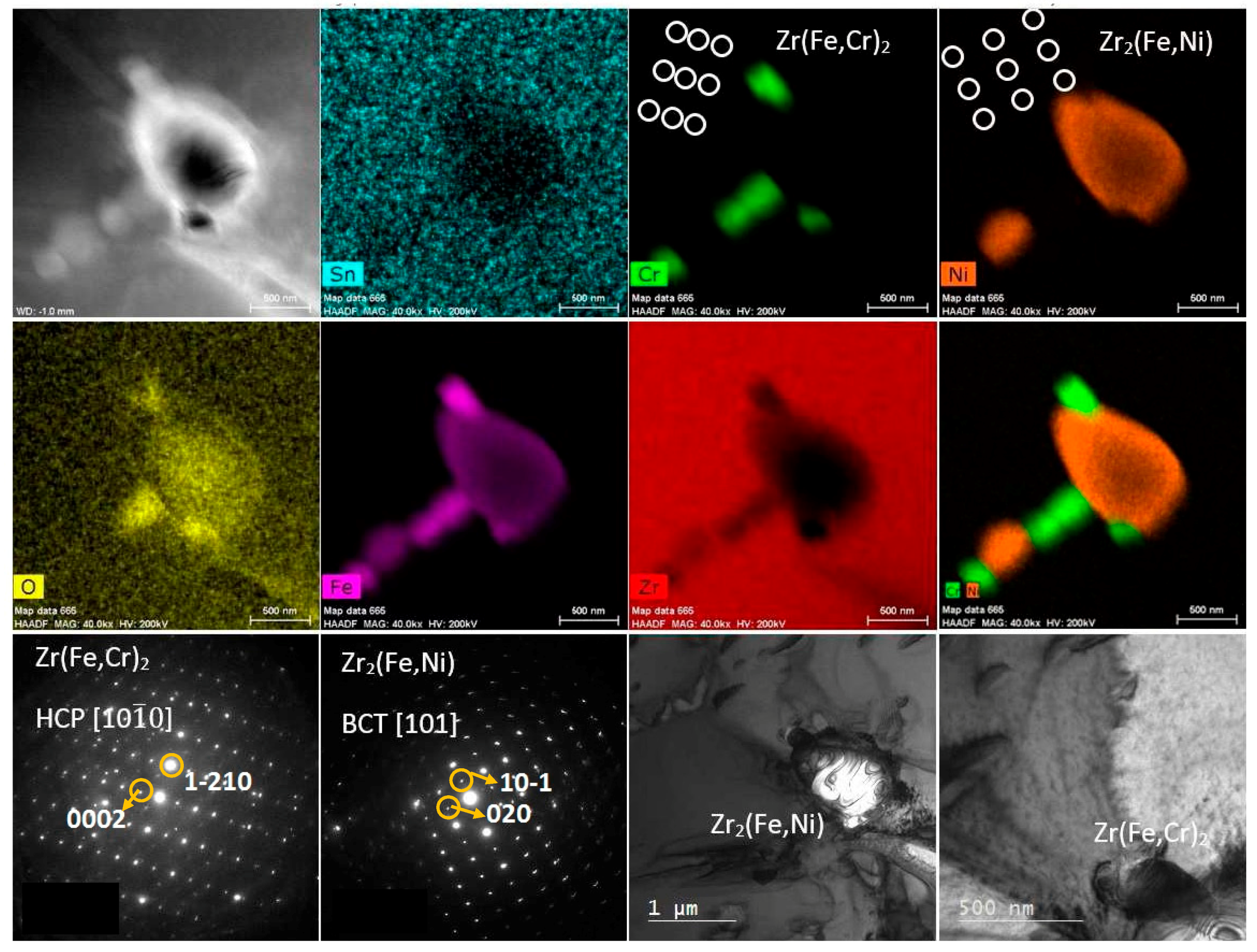
The pure zirconium used is the same as the previous paper [15]; is is 99.8% pure with Hf, Sn, Ni, Fe, C, and O present as impurities. The microstructure of pure zirconium is composed of near equiaxed grains of ~5 µm diameter. The zirconium alloy used is Zircaloy-2 with a grain size of >5 µm (many with an elongated shape shown in Figure 1), which was mechanically ground to thin foils and subsequently electropolished using a solution of 5% HClO4 in methanol at −40 °C. Optical micrographs, TEM (Company, FEI, Hillsboro, OR, USA) analysis, and scanning transmission electron microscopy associated with energy-dispersive X-ray spectroscopy (STEM-EDS) (FEI, Hillsboro, OR, USA) mapping done on an FEI Technai Osiris (FEI, Hillsboro, OR, USA) are presented in Figure 1, which shows the distribution of alloying elements in the secondary phase precipitates present in Zircaloy-2 used in the irradiation experiments. Alloying elements Zircaloy-2 contains 1.5 wt % Sn, 0.15% Fe, 0.1% Cr, and 0.05% Ni and 1000 wppm oxygen. From EDS element maps (Cr, Fe, Ni, O, Sn, Zr, and Cr + Ni) in Figure 1, Sn mostly remains in solid solution in the α-phase, O in the α-phase, and slightly enriched in intermetallics, whereas the other alloying elements are mostly contained in intermetallic precipitates: Zr(Fe,Cr)2 and Zr2(Fe,Ni). Figure 1 indicates these precipitates mostly with irregular shape, in sizes from 100 nm to ~1 µm. Similarly, the detailed analysis on intermetallic precipitates in Figure 2 shows the presence of two types of intermetallics present in the microstructure: Zr(Fe,Cr)2 with hexagonal close-packed (HCP) structure and Zr2(Fe,Ni) with body-centred tetragonal (BCT) structure, as confirmed by selected-aperture electron diffraction pattern (SAEDP).
In situ irradiation experiments were done at the intermediate voltage electron microscope coupled with tandem accelerator (IVEM-Tandem) at Argonne National Laboratory. The 1 MeV Kr ion irradiation experiments were done at 573 and 773 K from 0.007 to 0.8 dpa. Details of damage calculations, experimental procedures, and data collection methods can be reviewed elsewhere [15]. The nucleation and clustering behaviour of vacancies and interstitials by cascade collapse can be studied by calculating the parameter Defect Yield (DY) first defined by Merkle [23,24],
where NL is the number of loops/unit area and Nc is the number of cascades/unit area. In the heavy ion irradiations commonly used for this type of investigation, Nc is taken as the ion dose per unit area.
3. Results
3.1. Ion Irradiation
Zircaloy-2 was irradiated at 573 K and 773 K to monitor the formation of prismatic dislocation loops. These loops are visible when imaged with g ~ close to beam direction [0001].
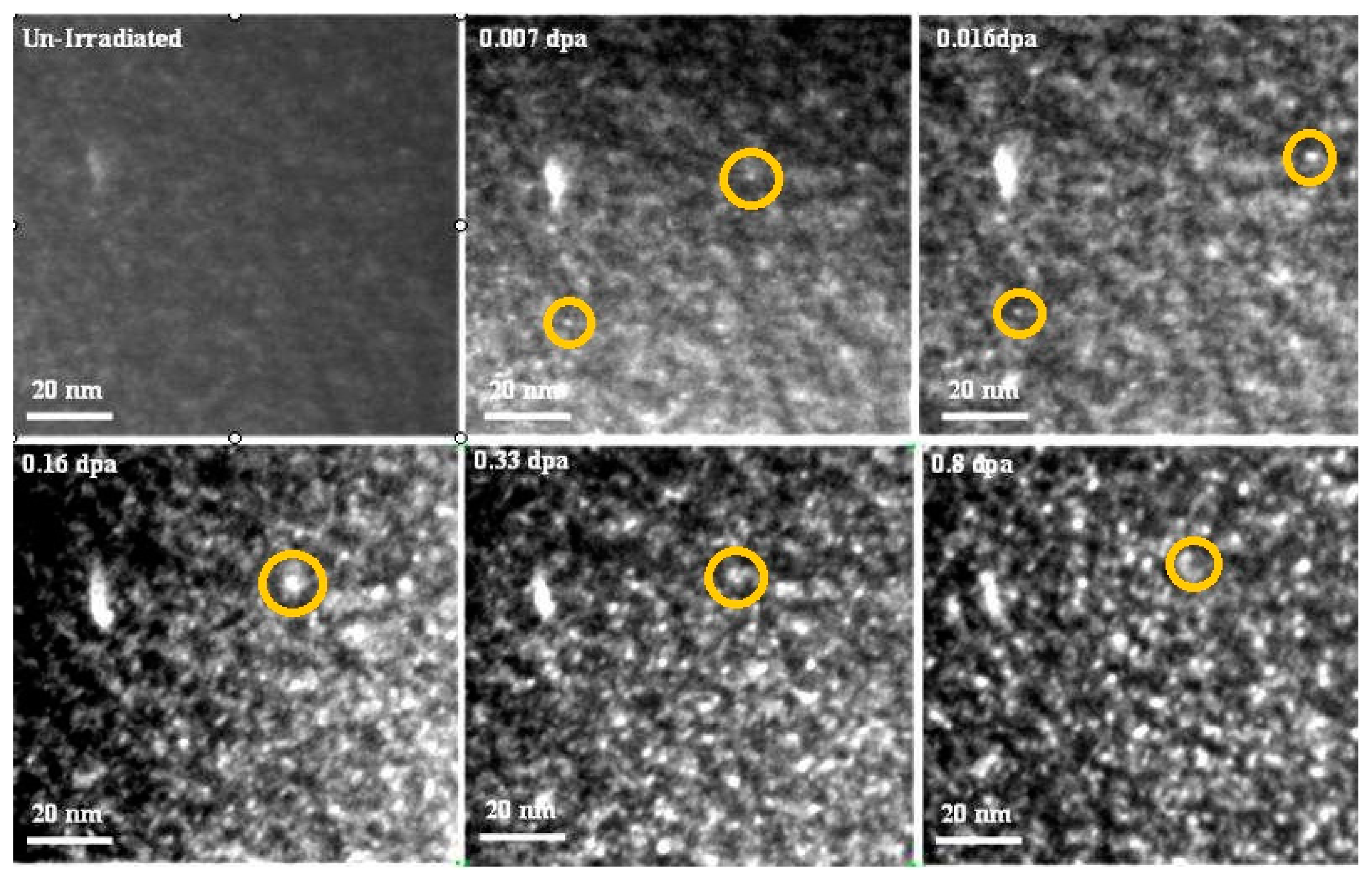
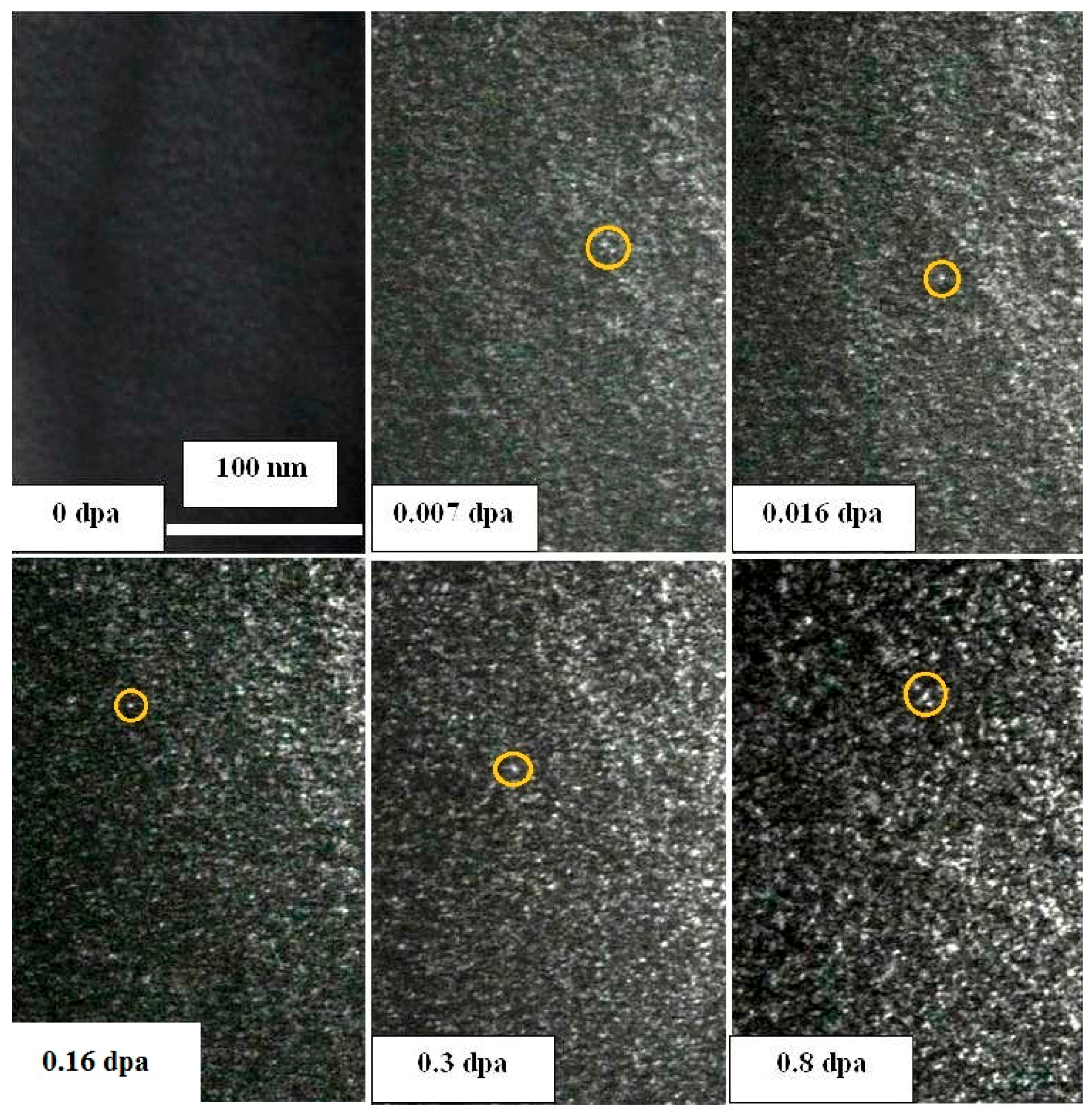
Figure 3 presents a series of dark field micrographs showing the formation of prismatic defects in Zircaloy-2 at 773 K. The pre-irradiation microstructure shows a fairly clean sample surface, except for small hydrides in the contrast of white dots. However, at the first observed dose level 0.007 dpa, small defect clusters appear in very weak contrast. The mean size of these clusters was recorded as ~2 nm. As the irradiation dose increased to 0.016 dpa, the mean size of these defect clusters grew slightly to 2.3 nm, and these loops showed much better contrast as compared to those observed at 0.007 dpa. As the ion dose further increased to 0.8 dpa, the loop size and DY increased with dose, as plotted in Figure 4.
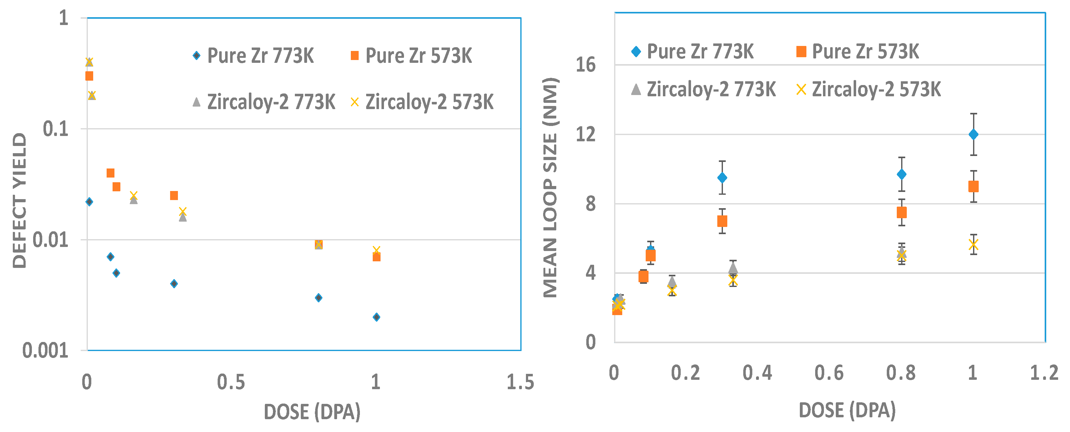
The DY calculated from Equation (1) at each dose level, plotted as a function of dose, at each irradiation temperature has been provided in Figure 4. From Figure 4 it is clear that the DY decreases with dose. The comparison of Zircaloy-2 and pure Zr data shows that the presence of alloying elements results in a higher DY at 773 K.
In situ TEM analysis on the prismatic defect formation at 573 K is presented in Figure 5. Dark field TEM micrographs were taken under similar diffraction conditions and at the same dose levels as at 773 K. Irradiated microstructures at different dose levels show somewhat similar microstructure to those observed at 773 K, except for the finer loop sizes and slightly higher DY, as shown in Figure 4.
To study the effect of alloying elements, the DY and mean size of dislocation loops were compared to pure Zr data reported in our previous paper [15]. Comparison between pure Zr and Zircaloy-2 shows that a higher number of loops nucleate in Zircaloy-2, as compared to pure Zr at 773 K, whereas loop size was found to be much smaller in Zircaloy-2 as compared to pure Zr. However, this trend does not repeat in the irradiation of two materials at 573 K.
3.2. MD Simulation
In order to further investigate and explain the differences seen in the loops’ morphology and defect clustering at different irradiation temperatures, Molecular Dynamics (MD) simulations were carried out in α-Zr. The system is first held at a given temperature for 10 ps to achieve thermal equilibrium, then one PKA is introduced into the system, and the production-run lasts for 60 ps. Periodic boundary conditions and a various-time-step approach are applied in the current calculations. Wigner-Seize method and common-neighbor analysis are employed to analyze the defects [25]. The results of MD simulation show the temperature dependence of defect cluster distributions at the time of defect nucleation at very low doses, which is then reflected in the DY and size data at higher doses, which can be observed experimentally. The Zr potential selected for the current simulations was the Embedded Atom Method (EAM) potential developed by Mendeleev and Ackland [25]. The size of the simulation block was 72 × 41 × 45 unit cells, with a total of 531,360 atoms inside. This size of the simulation box is sufficient for the selected PKA energy. In displaced cascade simulations, the PKA (Primary Knock-on Atom) energy is given as 20 keV, and the simulation temperature is set as 600 K or 800 K (close to experimental temperatures). The simulation system is first held at either 600 K or 800 K for 10 ps to achieve thermal equilibrium, then one PKA is introduced into the system, and the production runs of duration out to 60 ps are followed. For each condition, 20 simulations with different PKA positions and recoil directions are carried out. Periodic boundary condition and various time-step approaches are applied in the MD simulations.
Figure 6 illustrates the interstitial cluster size distributions at 600 K and 800 K. For the interstitial clusters with no more than 20 interstitial atoms, the cluster distributions are similar at 600 K and 800 K. Moreover, large interstitial clusters containing more than 40 interstitials are produced at both temperatures. The main difference between the two temperatures is that with the increase of the temperature from 600 K to 800 K, the number of interstitial clusters with 20 to 40 interstitials per cascade decreases with increased temperature.
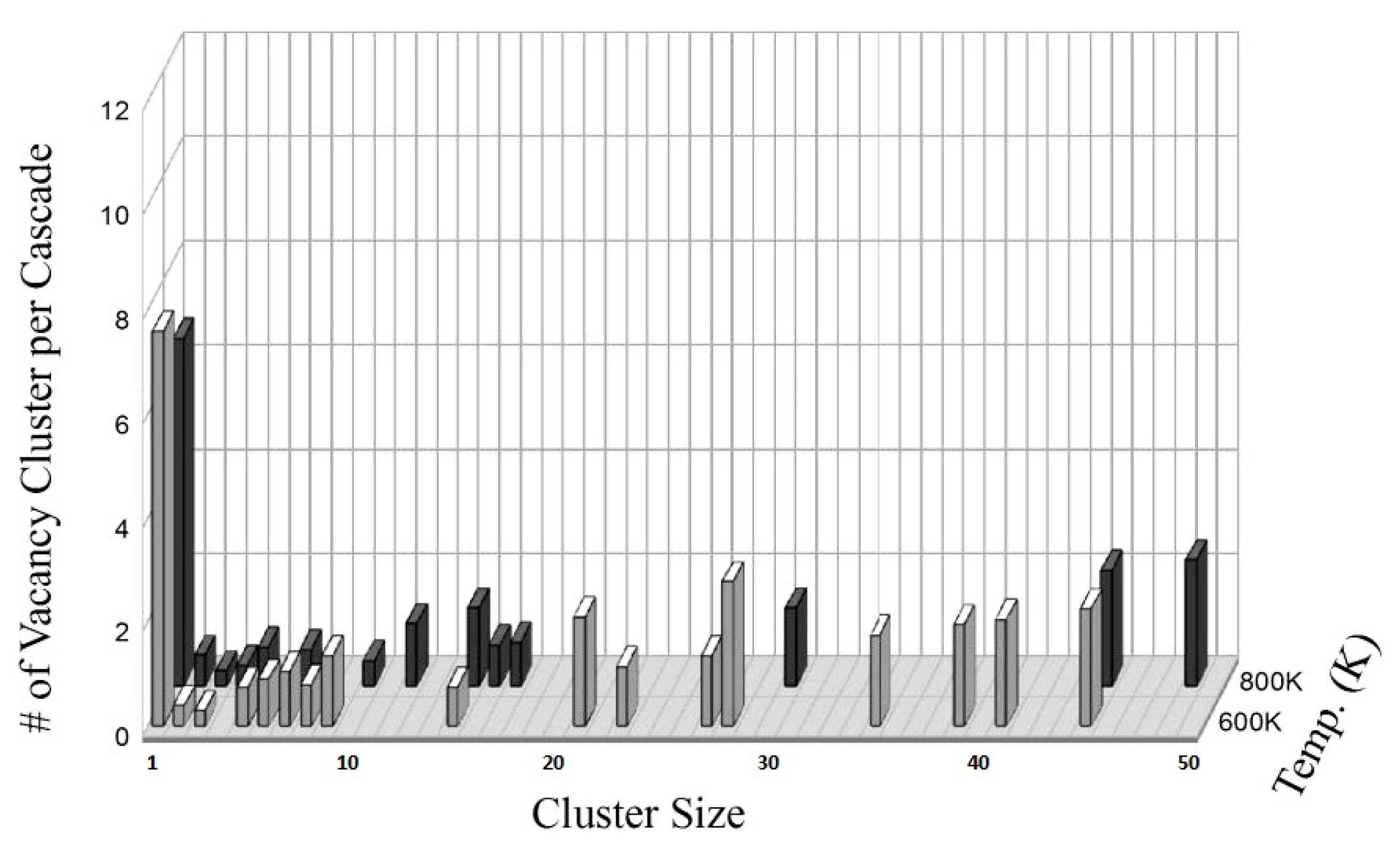
A similar tendency of cluster distributions is also observed for vacancy clusters, as shown in Figure 7.
The length of a defect cluster with 21 to 50 interstitial atoms or vacancies ranges from 1 to 3 nm. TEM analysis at very low ion doses can indeed resolve such small vacancy or interstitial clusters. Furthermore, MD simulations show that a higher number of defect clusters are produced at 600 K than at 800 K. In terms of production bias, the MD investigation conducted here showed that more vacancy clusters are produced than interstitial clusters at 600 K. Most of the vacancy clusters consist of three {} faces as a triangular prism structure and lie on the basal plane and the interstitial cluster extends along the <0002> direction with an irregular structure [19,21]. The total number of vacancy and interstitial clusters produced at 600 K and 800 K were counted, and are summarized in Table 1.
4. Discussion
4.1. Prismatic Loop Formation
The above presented results show the formation of small prismatic dislocation loops in the form of small defect clusters. The small size and low formation dose of these defect clusters suggest that these loops may be nucleated directly from the cascade collapse in the prism plane. The small white features, which show very weak contrast in the TEM sample, indicate defect cluster formation. The clusters then develop into larger prismatic loops, with a slightly larger size as the dose is increased to 0.016 dpa. Indeed, these loops were reported to form in MD computations in α-Zirconium before [26], but were not commonly experimentally observed/reported due to the availability and inspection mostly of neutron irradiated Zr in the literature, with most samples at relatively high doses.
MD simulations have provided a great insight into the formation of prismatic loops as it has been reported that most of the small interstitial clusters produced in the cascade have the form of a dislocation loop with Burgers vector . Point defect clusters in the prismatic plane always relax to form perfect dislocation loops with <a>-type Burgers vector [27]. Small interstitial clusters in the form of dislocations and the collapse of 24-vacancy clusters to a prismatic dislocation loop with Burgers vector were reported by Wooding et al. [19] and Gao et al. [20]. These small clusters have not been observed previously in the TEM. We see that these small clusters can be resolved and observed in the TEM, if they exist, by using in situ irradiation experiments. The current results provide, to our knowledge, the first experimental confirmation of the formation of these small clusters in Zr. The lower DY observed in the TEM at higher temperature can be directly correlated to lower defect cluster production at higher temperature. At 773 K, a smaller number of both vacancy and SIA clusters are produced after the cascade collapse, as compared to 573 K. At the higher irradiation temperature, vacancies and SIAs can diffuse across larger distances and therefore enhance the recombination of vacancies and SIAs. This also results in the growth of a limited number of clusters, and hence a lower DY and a larger loop size. The similar trends of DY vs. temperature and loop size vs. temperature were also recently found in other materials regardless of their different crystal structures, such as in bcc pure Fe [28,29,30,31] and pure W [32,33,34], and in fcc pure Ni [35] and Ni alloys [36].
4.2. Influence of Alloy Elements
A comparison of loop formation in Zircaloy-2 and pure Zr clarifies the role of alloying and impurity elements in defect nucleation and growth. At 773 K, the higher DY in Zircaloy-2 as compared to pure Zr, starting from the low dose, suggests that there has been more defect clustering and nucleation in Zircaloy-2, perhaps due to the presence of a larger number of nucleation sites in the form of solute atoms/clusters. Once a defect cluster nucleates in Zircaloy-2, its growth rate is much smaller than in pure Zr. This suggests that dislocation loops are receiving a lower flux of point defects in Zircaloy-2, leading to much finer dislocation loops.
It is well understood that atoms of alloying elements act as preferential sites for loop nucleation. A larger number of solute alloying elements in Zircaloy-2 provide more sites for defect nucleation resulting in a higher DY than in pure Zr. There is a significant amount of oxygen in Zircaloy-2 (1000 wppm) as shown by the STEM-EDS analysis presented in Figure 2. Oxygen is present in the alpha phase (uniform distribution), while the secondary phase precipitates are rich in oxygen as well. Hellio et al. [13] have shown that the presence of oxygen in Zirconium can decrease loop growth by increasing the vacancy migration energies due to segregation of oxygen to the dislocation loops. However, there is a similar amount of O present in “pure” Zr discussed in [15], approximately 900 wppm.
An increase in defect density and a decrease in loop size by the addition of substitutional solutes in Zr has been reported, e.g., due to the presence of Nb by Buckley and Manthorpe [12]. More relevant to the present study, loop growth rate is decreased significantly due to the presence of Sn, attributed to the change of the point defect mobility and to enhanced vacancy-interstitial recombination by Hinks [22]. Indeed, it has been reported that Sn is a very important element in zirconium, affecting radiation damage significantly: Hood suggests that Sn at low concentrations (0.l–0.2%) has little influence, whereas the high-Sn (1.5%) alloys show the strong effects of Sn on radiation damage by increasing vacancy trapping and recombination possibilities [37]. Looking at the chemistry of Zircaloy-2, the only major alloying elements present in the alpha solid solution are Sn and O, whereas other elements are present in the intermetallic precipitates. Compared to the pure Zr composition, it is reasonable to assume that Sn is the most important alloying element causing the differences observed between the defect nucleation in pure Zr and Zirclaoy-2 at lower doses where irradiation induced dissolution of Fe and Cr from the intermetallics will be negligible. At higher doses, both Fe and Cr diffuse from the intermetallic precipitates into the alpha Zr matrix through an interstitial diffusion mechanism at similar diffusion rates and can alter the microstructural evolution mechanisms significantly [2,10].
It should be noted that the influence of alloy elements on defect nucleation also varies with temperature. Compared to irradiation at 573 K, the alloy elements appear to be more available to offer nucleation sites for defects at higher temperatures, which might be related to the enhanced mutual trapping between those alloy atoms and point defects at elevated temperatures.
5. Summary and Conclusions
The current study reveals the differences in the nucleation, growth behaviour, and temperature dependence of prismatic loops in Zr and Zircaloy-2. The following conclusions can be drawn:
- Zr and Zircaloy-2 exhibit different defect clustering behaviour under a similar irradiation environment. Formation of prismatic defects is dependent on both the temperature and the alloy elements.
- MD simulations show that the lower DY at higher temperature is a result of a lower number of defect clusters produced during cascade collapse at higher irradiation temperatures in pure Zr.
- DY is higher in Zircaloy-2 as compared to pure Zr at 773 K, which can be attributed to the higher number of nucleation sites for the defect clusters. However, the size of prismatic loops is found to be much smaller in Zircaloy-2 compared to pure Zr due to the presence of alloying element Sn and its effect on point defect recombination.
Supplementary Materials
The following are available online at https://0-www-mdpi-com.brum.beds.ac.uk/2076-3417/7/8/854/s1.
Acknowledgments
The authors would like to thank MITACS for financial support under the Mitacs Elevate program and acknowledge support from the industrial partner Kinetrics. This work was also supported by the NSERC/UNENE Industrial Research Chair in Nuclear Materials at Queen’s. In situ irradiation studies were accomplished at the Electron Microscopy Centre for Materials Research at Argonne National Laboratory supported by the US Department of Energy Office of Science and operated under Contract No. DE-AC02-06CH11357 by U. Chicago, Argonne, LLC. We thank Mark Kirk, Pete Boldo, and Ed Ryan of Argonne National Lab for their help on the microscopy and ion beam facility.
Author Contributions
Zhongwen Yao, Mark Daymond and Yasir Idrees planned the experimental work, and wrote the paper. Zhongwen Yao and Yasir Idrees carried out the experiments and analysed the data. Sali Di carried out the molecular dynamics simulation work.
Conflicts of Interest
The authors declare no conflict of interest.
References
- Azevedo, C.R.F. Selection of fuel cladding material for nuclear fission reactors. Eng. Fail. Anal. 2011, 18, 1943–1962. [Google Scholar] [CrossRef]
- Onimus, F.; Béchade, J.L. Radiation effects in zirconium alloys. In Comprehensive Nuclear Materials; Elsevier: Amsterdam, The Netherlands, 2012; Volume 4, pp. 1–31. [Google Scholar]
- Carpenter, G.J.C.; Watters, J.F. A study of electron irradiation damage in zirconium using a high voltage electron microscope. J. Nucl. Mater. 1981, 96, 213–226. [Google Scholar] [CrossRef]
- Gulden, T.D.; Bernstein, I.M. Dislocation loops in irradiated zirconium. Philos. Mag. 1966, 14, 1087–1091. [Google Scholar] [CrossRef]
- Kelly, P.M.; Blake, R.G. The chracterization of dislocation loops in neutron irradiated zirconium. Philos. Mag. 1973, 28, 415–426. [Google Scholar] [CrossRef]
- Northwood, D.O.; Fidleris, V.; Gilbert, R.W.; Carpenter, G.J.C. Dislocation loop generation and irradiation growth in a zirconium single crystal. J. Nucl. Mater. 1976, 61, 123–130. [Google Scholar] [CrossRef]
- Northwood, D.O. Irradiation damage in zirconium and its alloys. Atom. Energy Rev. 1977, 15, 547–610. [Google Scholar]
- Gilbert, R.W.; Farrell, K.; Coleman, C.E. Damage structure in zirconium alloys neutron irradiated at 573 to 923 K. J. Nucl. Mater. 1979, 84, 137–148. [Google Scholar] [CrossRef]
- Griffiths, M. A review of microstructure evolution in zirconium alloys during irradiation. J. Nucl. Mater. 1988, 159, 190–218. [Google Scholar] [CrossRef]
- Jostsons, A.; Kelly, P.M.; Blake, R.G. The nature of dislocation loops in neutron irradiated zirconium. J. Nucl. Mater. 1977, 66, 236–256. [Google Scholar] [CrossRef]
- Northwood, D.O.; Gilbert, R.W.; Bahen, L.E.; Kelly, P.M.; Blake, R.G.; Jostsons, A.; Madden, P.K.; Faulkner, P.; Bell, W.; Adamson, R.B. Characterization of neutron irradiation damage in zirconium alloys—An international ‘round-robin’ experiment. J. Nucl. Mater. 1979, 79, 379–394. [Google Scholar] [CrossRef]
- Buckley, S.N.; Manthorpe, S.A. Dislocation loop nucleation and growth in zirconium-2.5wt % niobium alloy during 1 MeV electron irradiation. J Nucl. Mater. 1980, 90, 169–174. [Google Scholar] [CrossRef]
- Hellio, C.; de Novion, C.H.; Boulanger, L. Influence of alloying elements on the dislocation loops created by Zr+ ion or by electron irradiation in α-zirconium. J. Nucl. Mater. 1988, 159, 368–378. [Google Scholar] [CrossRef]
- Adamson, R.B.; Bell, W.L.; Lee, D. Use of ion bombardment to study irradiation damage in zirconium alloys. Zirconium Nucl. Appl. 1974, 551, 215–228. [Google Scholar]
- Idrees, Y.; Yao, Z.; Kirk, M.A.; Daymond, M.R. In-situ study of defect accumulation in zirconium under heavy ion irradiation. J. Nucl. Mater. 2013, 433, 95–107. [Google Scholar] [CrossRef]
- Faulkner, D.; Styles, R.C. Radiation damage simulation experiments in zirconium. In Proceedings of the Thirty-First Annual EMSA Meeting, New Orleans, LA, USA, 14 August 1973. [Google Scholar]
- Griffiths, M.; Gilbert, R.W.; Coleman, C.E. Grain boundary sinks in neutron-irradiated Zr and Zr-alloys. J. Nucl. Mater. 1988, 159, 405–416. [Google Scholar] [CrossRef]
- Wooding, S.J.; Bacon, D.J. A molecular-dynamics study of displacement cascades in α-zirconium. Philos. Mag. A 1996, 76, 1033–1051. [Google Scholar] [CrossRef]
- Wooding, S.J.; Howe, L.M.; Gao, F.; Calder, A.M.; Bacon, D.J. A molecular dynamics study of high-energy displacement cascades in α-zirconium. J. Nucl. Mater. 1998, 254, 191–200. [Google Scholar] [CrossRef]
- Gao, F.; Bacon, B.J.; Howe, L.M.; So, C.B. Temperature-dependence of defect creation and clustering by displacement cascades in α-zirconium. J. Nucl. Mater. 2001, 294, 288–298. [Google Scholar] [CrossRef]
- Voskoboinikov, R.E.; Osetsky, Y.N.; Bacon, D.J. Statistics of primary damage creation in high-energy displacement cascades in copper and zirconium. Nucl. Instrum. Methods Phys. Res. B 2006, 242, 68–70. [Google Scholar] [CrossRef]
- Hinks, J.A. A review of transmission electron microscope with in-situ ion irradiation. Nucl. Instrum. Methods Phys. Res. B 2009, 267, 3652–3662. [Google Scholar] [CrossRef]
- Merkle, K.L. Radiation-induced point defect clusters in copper and gold. Phys. Status Solidi 1966, 18, 173–188. [Google Scholar] [CrossRef]
- Merkle, K.L. Radiation Damage in Reactor Materials; IAEA: Vienna, Austria, 1969; Volume 1, pp. 159–170. [Google Scholar]
- Di, S.; Yao, Z.; Daymond, M.; Gao, F. Molecular dynamics simulations of irradiation cascades in alpha-zirconium under macroscopic strain. Nucl. Instrum. Methods Phys. Res. B 2013, 303, 95–99. [Google Scholar] [CrossRef]
- Mendelev, M.I.; Ackland, G.J. Development of an interatomic potential for the simulation of phase transformations in zirconium. Philos. Mag. Lett. 2007, 87, 349–359. [Google Scholar] [CrossRef]
- De Diego, N.; Osetsky, Y.N.; Bacon, D.J. Structure and properties of vacancy and interstitial clusters in α-zirconium. J. Nucl. Mater. 2008, 374, 87–94. [Google Scholar] [CrossRef]
- Yao, Z.; Hernandez-Mayoral, M.; Jenkins, M.L.; Kirk, M.A. Heavy ion irradiations of Fe and Fe-Cr model alloys part 1: Damage evolution in thin foils at lower doses. Philos. Mag. 2008, 88, 2851–2880. [Google Scholar] [CrossRef]
- Hernandez-Mayoral, M.; Yao, Z.; Jenkins, M.L.; Kirk, M.A. Heavy ion irradiations of Fe and Fe-Cr model alloys part 2: Damage evolution in thin foils at higher doses. Philos. Mag. 2008, 88, 2881–2897. [Google Scholar] [CrossRef]
- Yao, Z.; Jenkins, M.L.; Hernandez-Mayoral, M.; Kirk, M.A. The temperature dependence of heavy ion damage in Fe: A microstrcuture transition at elevated temperatures. Philos. Mag. 2010, 90, 4623–4634. [Google Scholar] [CrossRef]
- Jenkins, M.L.; Yao, Z.; Hernandez-Mayoral, M.; Kirk, M.A. Dynamic observations of heavy ion damage in Fe and Fe-Cr alloys. J. Nucl. Mater. 2009, 389, 197–202. [Google Scholar] [CrossRef]
- Mason, D.R.; Yi, X.; Kirk, M.A.; Dudarev, S.L. Elastic trapping of dislocation loops in cascades in ion-irradiated tungsten foils. J. Phys. Condens. Matter 2014, 26, 375701. [Google Scholar] [CrossRef] [PubMed]
- Sand, A.E.; Dudarev, S.L.; Nordlund, K. High-energy collision cascades in tungsten: Dislocation loops structure and clustering scaling laws. EPL 2013, 103, 46003. [Google Scholar] [CrossRef]
- Yi, X.; Sand, A.E.; Mason, D.R.; Kirk, M.A.; Roberts, S.G.; Nordlund, K.; Dudarev, S.L. Direct observation of size scaling and elastic interaction between nano-scale defects in collision cascades. EPL 2015, 110, 36001. [Google Scholar] [CrossRef]
- Yao, Z. The Relationship between the Irradiation Induced Damage and the Mechanical Properties of Single Crystal Ni. Ph. D. Thesis, École polytechnique fédérale de Lausanne, Lausanne, Switzerland, 2005. [Google Scholar]
- Zhang, H.K.; Yao, Z.; Judge, C.; Griffiths, M. Microstructure evolution of CANDU spacer material Inconel X-750 under in-situ ion irradiation. J. Nucl. Mater. 2013, 443, 49–58. [Google Scholar] [CrossRef]
- Hood, G.M. Point defect diffusion in α-Zr. J. Nucl. Mater. 1988, 159, 149–175. [Google Scholar] [CrossRef]
Figure 1.
(a) Optical micrograph on Zircaloy-2, showing elongated grains. Inset shows the transmission electron microscopy (TEM) bright field micrograph of the grain structure. (b) Low magnification scanning transmission electron microscopy associated with energy-dispersive X-ray spectroscopy STEM-EDS mapping on Zircaloy-2 showing the distribution of intermetallic precipitates. The scale bar of those maps is 3 µm. The brightness of colors in element map indicates their concentration. The higher concentration shows in brighter contrast, and the darker area means depletion of this element.

Figure 2.
STEM-EDS elemental mapping on intermetallic precipitates present in Zircaoy-2. Corresponding selected-aperture electron diffraction pattern (SAEDP) and TEM bright field micrographs are given. Each micrograph of precipitates is labelled for it chemistry and shows crystallinity from SAEDP. The diffraction patterns well indicated that Zr(Fe,Cr)2 particles are in hexagonal close-packed (HCP) structure (HCP) structure and Zr2(Fe,Ni) particles are in body-centred tetragonal (BCT) structure. The scale bar in element maps is 500 nm.

Figure 3.
Series of dark field micrographs, taken during in situ irradiation experiment on Zircaloy-2 at 773 K, showing the formation of <a>-type loops. The bright dots are recognized as dislocation loops, among which a representative loop was circled in each dose.
Figure 3.
Series of dark field micrographs, taken during in situ irradiation experiment on Zircaloy-2 at 773 K, showing the formation of <a>-type loops. The bright dots are recognized as dislocation loops, among which a representative loop was circled in each dose.

Figure 4.
Mean loop size and defect yield in Zircaloy-2 plotted as a function of dose at both irradiation temperatures, compared with pure Zr.
Figure 4.
Mean loop size and defect yield in Zircaloy-2 plotted as a function of dose at both irradiation temperatures, compared with pure Zr.

Figure 5.
Series of dark field micrographs, taken during in situ irradiation experiment on Zircaloy-2 at 573 K, showing the formation of <a>-type loops, which present as bright dots in dark field. The orange circles in each micrograph enclose one or more dot-like loops.
Figure 5.
Series of dark field micrographs, taken during in situ irradiation experiment on Zircaloy-2 at 573 K, showing the formation of <a>-type loops, which present as bright dots in dark field. The orange circles in each micrograph enclose one or more dot-like loops.

Figure 6.
Interstitial cluster distribution at 600 K (white column) and 800 K (gray column).

Figure 7.
Vacancy cluster distribution at 600 K (white column) and 800 K (gray column).


Table 1.
Total number of interstitial and vacancy clusters in 20 simulations at 600 K and 800 K.
| Cluster Size (Number of Defects) | 600 K | 800 K | ||
|---|---|---|---|---|
| SIA | V | SIA | V | |
| 5–10 | 11 | 14 | 8 | 7 |
| 11–20 | 5 | 1 | 5 | 6 |
| 21–40 | 4 | 8 | 1 | 1 |
| 41–50 | 1 | 2 | 1 | 2 |
| Summary | 21 | 25 | 15 | 16 |
© 2017 by the authors. Licensee MDPI, Basel, Switzerland. This article is an open access article distributed under the terms and conditions of the Creative Commons Attribution (CC BY) license (http://creativecommons.org/licenses/by/4.0/).
Share and Cite
MDPI and ACS Style
Yao, Z.; Daymond, M.; Di, S.; Idrees, Y. Irradiation Induced Defect Clustering in Zircaloy-2. Appl. Sci. 2017, 7, 854. https://0-doi-org.brum.beds.ac.uk/10.3390/app7080854
AMA Style
Yao Z, Daymond M, Di S, Idrees Y. Irradiation Induced Defect Clustering in Zircaloy-2. Applied Sciences. 2017; 7(8):854. https://0-doi-org.brum.beds.ac.uk/10.3390/app7080854
Chicago/Turabian StyleYao, Zhongwen, Mark Daymond, Sali Di, and Yasir Idrees. 2017. "Irradiation Induced Defect Clustering in Zircaloy-2" Applied Sciences 7, no. 8: 854. https://0-doi-org.brum.beds.ac.uk/10.3390/app7080854
Note that from the first issue of 2016, this journal uses article numbers instead of page numbers. See further details here.