Measurement Matrix Analysis and Radiation Improvement of a Metamaterial Aperture Antenna for Coherent Computational Imaging


Key Laboratory of High Speed Circuit Design and EMC of Ministry of Education, School of Electronic Engineering, Collaborative Innovation Center of Information Sensing and Understanding, Xidian University, Xi’an 710071, China
*
Author to whom correspondence should be addressed.
Appl. Sci. 2017, 7(9), 933; https://0-doi-org.brum.beds.ac.uk/10.3390/app7090933
Submission received: 26 July 2017
/
Revised: 18 August 2017
/
Accepted: 7 September 2017
/
Published: 12 September 2017
(This article belongs to the Special Issue Metasurfaces: Physics and Applications)
Abstract
:A metamaterial aperture antenna (MAA) that generates frequency-diverse radiation field patterns has been introduced in the context of microwave wave imaging to perform compressive image reconstruction. This paper presents a new metamateriapl aperture design, which includes two kinds of metamaterial elements with random distribution. One is a high-Q resonant element whose resonant frequency is agile, and the other one is a low-Q element that has a high radiation efficiency across frequency band. Numerical simulations and measurements show that the radiation efficiency of up to 60% can be achieved for the MAA and the far-field patterns owns good orthogonality, when using the complementary electric-field-coupled (CELC) element and the complementary Jerusalem cross (CJC) element with a random distribution ratio of 4 to 1, which could be effectively used to reconstruct the target scattering scene.
1. Introduction
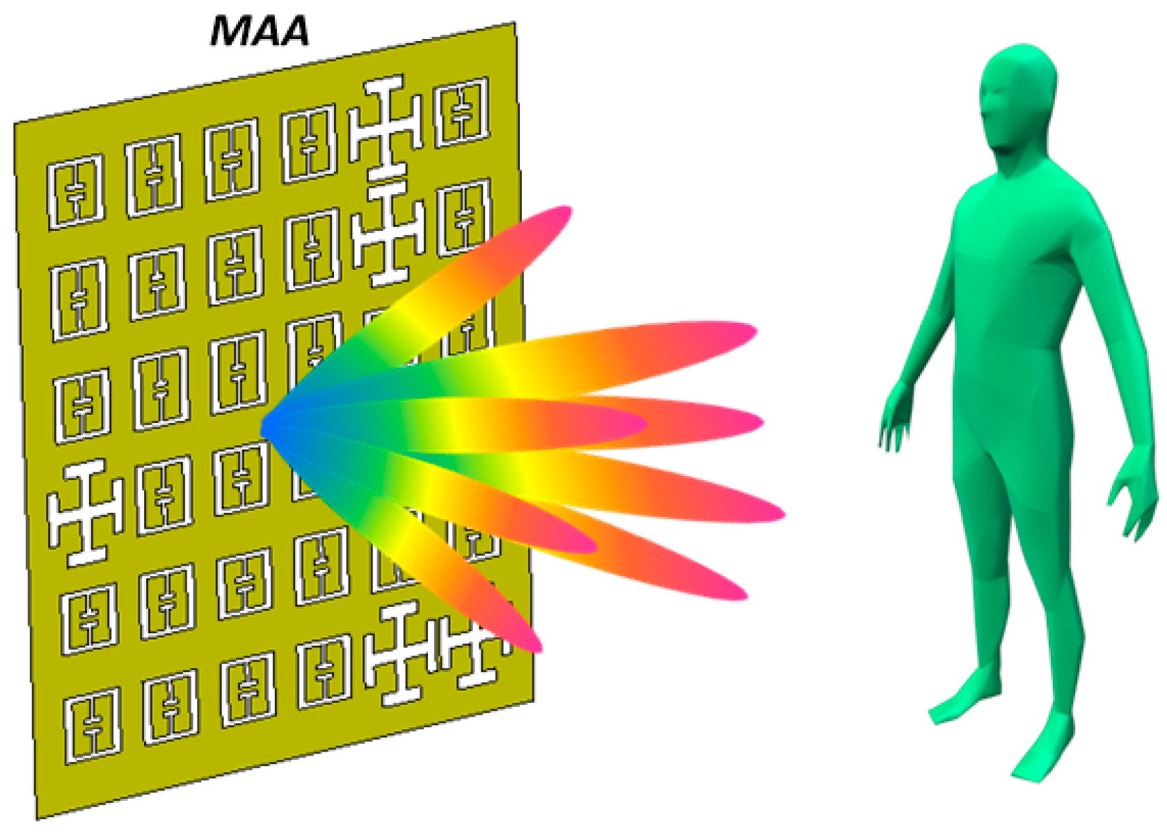
In recent years, several physical platforms based on metamaterial aperture antennas (MAAs) have been used to realize computational imaging, as shown in Figure 1. In general, all natural scenes can be compressed on some basis. Scenes can be perfectly reconstructed with significantly fewer measurement modes than the space bandwidth product (SBP) [1,2,3]. These measurement modes are composed of radiated field patterns of the metamaterial aperture antenna (MAA) at different frequencies. For image reconstruction schemes, which use an arbitrary set of measurement modes, it is essential that the modes are as orthogonal to each other as possible [4] so that the correlation of the modes or field patterns is small [5,6,7]. Since the measurement modes are indexed by frequency, the low correlation of field patterns can be interpreted as far-field patterns with strong frequency diversity. Hence, to obtain a metamaterial aperture that generates the frequency-agile far-field patterns that are as orthogonal as possible, elements distributed on the aperture must have a strong resonance with a high Q-value. Other approaches to frequency-diverse imaging have also been pursued, including multiply scattering structures, such as mode-mixing cavities and dynamic metamaterial apertures [8,9,10]. Fractal models have been used to design fractal antennas with very special properties: about one-tenth of a wavelength and a pre-fractal geometrical configuration [11] could be used in metamaterial miniaturized technology, which is needed for coherent imaging. The fractional signal, especially its geometrical interpretation, which gives a powerful mathematical tool to model the most advanced concepts of modern physics, could help us to build a simpler mathematical model of the relationship between the metamaterial aperture antenna and its radiation feature, which will improve the speed of full-wave simulation [12].The initial metamaterial aperture which consists of numerous subwavelength-resonant radiators present a trade-off between the Q factor and radiation efficiency (each resonator distributed on aperture is assigned a resonant frequency randomly selected from the bandwidth of operation) [13,14], and most of the power is radiated by the elements closest to the feed, resulting in poor aperture efficiency.
In this paper, the correlation of far-field patterns for metamaterial apertures with different modulations is analyzed, and a trade-off strategy between orthogonality of the far-field patterns and radiation efficiency of the MAA is proposed. The metamaterial aperture is composed of complementary electric-field-coupled elements (CELCs) [15] and complementary Jerusalem cross (CJC) [16] unit cells. The CELC element is strongly resonant with frequency diversity, while the CJC unit cell has high radiation efficiency across the frequency band. By analyzing the filling ratio of the two different elements on the MAA, a relatively low correlation of the far-field patterns and high radiation efficiency is obtained. MAAs with a 20 × 20 randomly distributed elements array are theoretically analyzed in the frequency band from 33 to 37 GHz. Numerical simulations show that the radiation efficiency of 60% can be achieved, which yields improved SNRs when using the complementary electric-field-coupled (CELC) element and the CJC element with a random distribution ratio of 4 to 1 on the aperture. A prototype of the MAA with 120 × 120 randomly distributed elements whose total size is 250 mm × 250 mm × 0.5 mm is fabricated to verify the effectiveness of the design and analysis procedure, and to show that the measured far-field patterns across the frequency band from 33 to 37 GHz could be used to effectively reconstruct the target scene with scatterers.
2. The Calculation for the Correlation of Far-Field Patterns of an MAA
In the context of compressed sensing, the measurement modes can be selected as the radiated far-field patterns of the MAA in a given frequency range. Consider the measurement matrix H, which corresponds to the frequency-diverse far-field patterns. H is an M × N matrix. M represents the quantity of the measurement modes, which is equal to the number of the sampled frequency points. N denotes the far-field pattern pixels at one frequency point, which is the product of the azimuth angles and elevation angles. The matrix reconstruction metric is the average mutual coherence μg, which is defined as follows [13].
Firstly, with the measurement matrix, the Gram matrix can be obtained [17,18]:
where the superscript represents the conjugate transpose of the matrix, and Hn is the measurement matrix H with normalized columns. The average mutual coherence is
As pointed out by Lipworth et al. [13], an increase in the Q-factor of the element on the metamaterial aperture causes μg to decrease, which indicates that less correlation between measurements represents better orthogonality of the far-field patterns. Here, the frequency quality factor Q can be defined as
where f0 is the center operating frequency, and 2Δf represents the frequency range, which the amplitude response decreases by 3 dB. Usually, when the operating frequency band is given, the center frequency f0 is fixed and the frequency interval Δf could be changed by selecting different resonant elements with varying frequency agility features. For the strongly resonant element with a high Q-value, its frequency selectivity is good, which means the Δf or the bandwidth is relatively small. By using this kind of element on the MAA, frequency-agile field patterns with good orthogonality can be obtained. As a result, the target scene can be perfectly reconstructed by utilizing a simple metamaterial aperture antenna instead of mechanical scanning or antenna arrays.
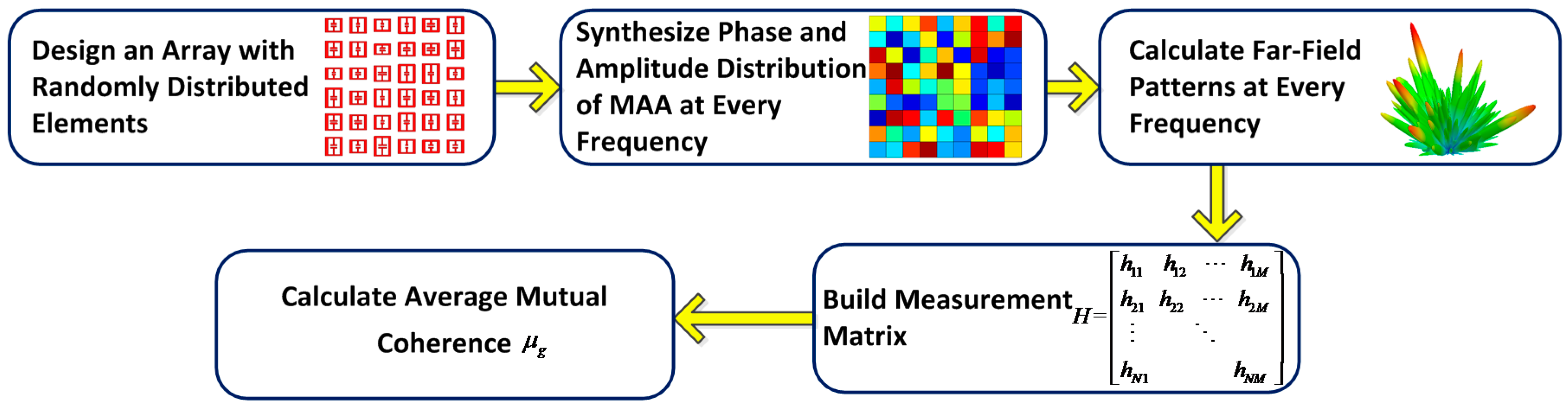
Figure 2 shows the flow chart for calculation procedure of μg. Firstly, an MAA with randomly distributed elements is designed. At each frequency point, the phase and amplitude responses of the elements on the MAA can be obtained by numerical simulations. Next, the far-field patterns across the frequency band can be calculated using array synthesis technology. Finally, far-field patterns form the measurement matrix and the average mutual coherence μg can be obtained. Here we will focus on the theoretical analysis for the variation of μg when the Q-factor of the resonant elements of the MAA changes.
3. An Analysis of Average Mutual Coherence μg
In order to obtain a set of frequency-diverse far-field patterns whose average mutual coherence μg is low, it is essential that different amplitude and phase distributions on one metamaterial aperture are realized at different frequencies from the point of antenna design. However, the strongly resonant elements with frequency-agile responses both on amplitude and phase responses are not realistically achievable. Hence, the phase and amplitude modulations of MAA are performed separately to analyze the average mutual coherence μg of its far-field patterns.
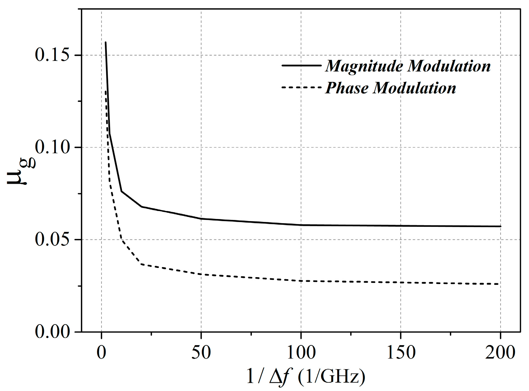
For the phase modulation of MAA, the phase distribution on the aperture antenna varies when frequency changes while the amplitude distribution on MAA is uniform. Here, 20 × 20 resonant elements with varying phase responses at different frequencies are randomly distributed on the metamaterial aperture antenna, which is analyzed by using array synthesis technology in the frequency band from 33 to 37 GHz. The average mutual coherence μg of the far-field patterns of the MAA is calculated using elements with varying Q-values (or Δf). When the Δf of the elements is changed from 0.005 to 0.5 GHz, the calculated μg varies from 0.02 to 0.13, as shown in Figure 3.
Similarly, for the amplitude modulation of MAA, the amplitude distribution on the aperture is diverse at different frequencies, while the phase distribution on MAA is constant. And 20 × 20 resonant elements with diverse amplitude responses in frequency are also distributed on the aperture randomly. By changing Δf, the average mutual coherence μg of the far-field patterns of the MAA is calculated. When the bandwidth Δf of the element is changed from 0.005 to 0.5 GHz, the calculated μg varies from 0.05 to 0.15. The comparison of μg between the phase and amplitude modulation is shown in Figure 3. It can be seen from Figure 3 that the calculated μg of phase modulation is slightly smaller than that of amplitude modulation. When the bandwidth of the element becomes smaller, the average mutual coherence becomes lower. However, the average mutual coherence becomes flat when Δf is less than 0.005 GHz. It is worth mentioning that the average mutual coherence is irrelevant with respect to the specific location of the center frequency, but it is relative to Δf. It is common that, at higher operating frequencies, such as the millimeter-wave frequency band, the resonant element often has a larger Δf (usually ≥0.1 GHz). Hence, it is much more difficult to design a resonant element with Δf ≤ 0.1 GHz at the millimeter-wave band, such as 35 GHz.
4. A Method of Improving the Radiation Efficiency of an MAA
In general, resonant elements with varying amplitude responses in frequency are realistically achievable. Specifically, different amplitude distributions of the elements on an MAA are represented by the varying radiation efficiencies on the aperture. However, there is a trade-off between the Q-factor and the radiation efficiency of these elements [19]. Additionally, an increase in the Q-factor of the element on the metamaterial aperture causes μg to decrease [13]. Hence, a trade-off between the average mutual coherence μg and the radiation efficiency of the MAA must be made.
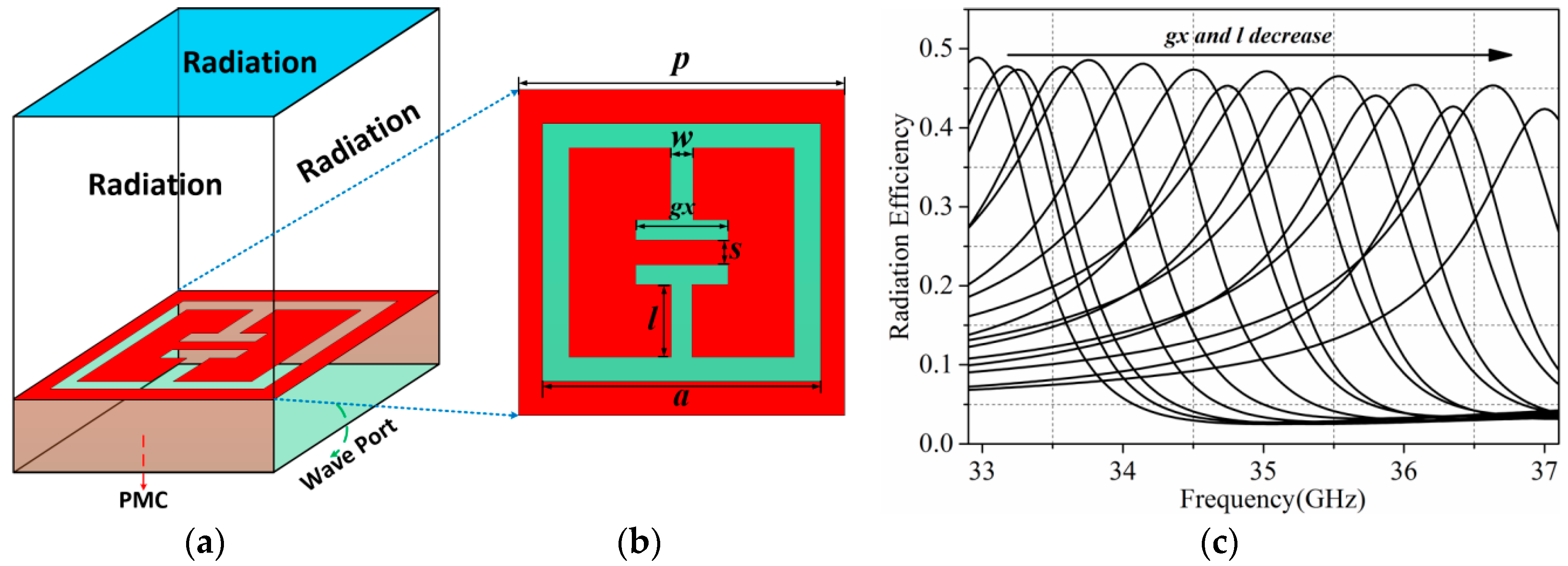
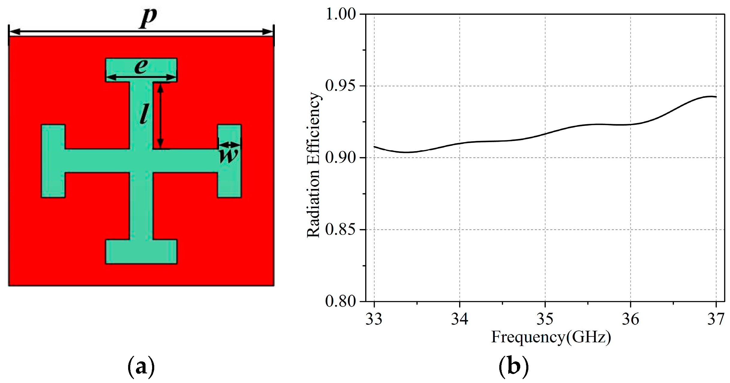
Usually the MAA is composed of all the strongly resonant elements, such as a CELC [15]. Figure 4 shows the radiation characteristic of a CELC element. The PMC (Perfect Magnetic Conductor) boundary used here is meant to represent the periodic boundary condition that is used to model an infinite metamaterial aperture antenna in practice. It can be seen that, when size parameters g and l decrease, the resonant frequency of the CELC increases and the CELC element has an agile radiation efficiency response across the frequency band. However, the element has a very low radiation efficiency, with a peak value of approximate 50% and a bandwidth of Δf ≈ 0.1 GHz. In this case, a low Q-factor element can be introduced to increase the radiation efficiency without significantly destroying μg. The CJC unit cell [16] is adopted, which has a low quality factor but a radiation efficiency that is superior to that of the CELC element, as shown in Figure 5.
In this paper, the improved strategy of the MAA design is a combination of CELC and CJC elements. However, the ratio of the CJC elements distributed on the aperture is crucial, which causes a balance problem between the μg and the radiation efficiency of the antenna. To illustrate this, we analyze the performances of the MAA with 20 × 20 elements, when the ratio of CJC elements changes from 0 to 50%. On the aperture, the CELC elements are used to generate frequency-diverse field patterns. The CJC elements that are used to improve the radiation efficiency are placed on the remaining part of the aperture with a certain ratio. Using a full-wave simulation tool, the radiation efficiency of the CJC element is obtained in the frequency band from 33 to 37 GHz, as shown in Figure 5b. It can be seen that the CJC element has a good radiation ability.
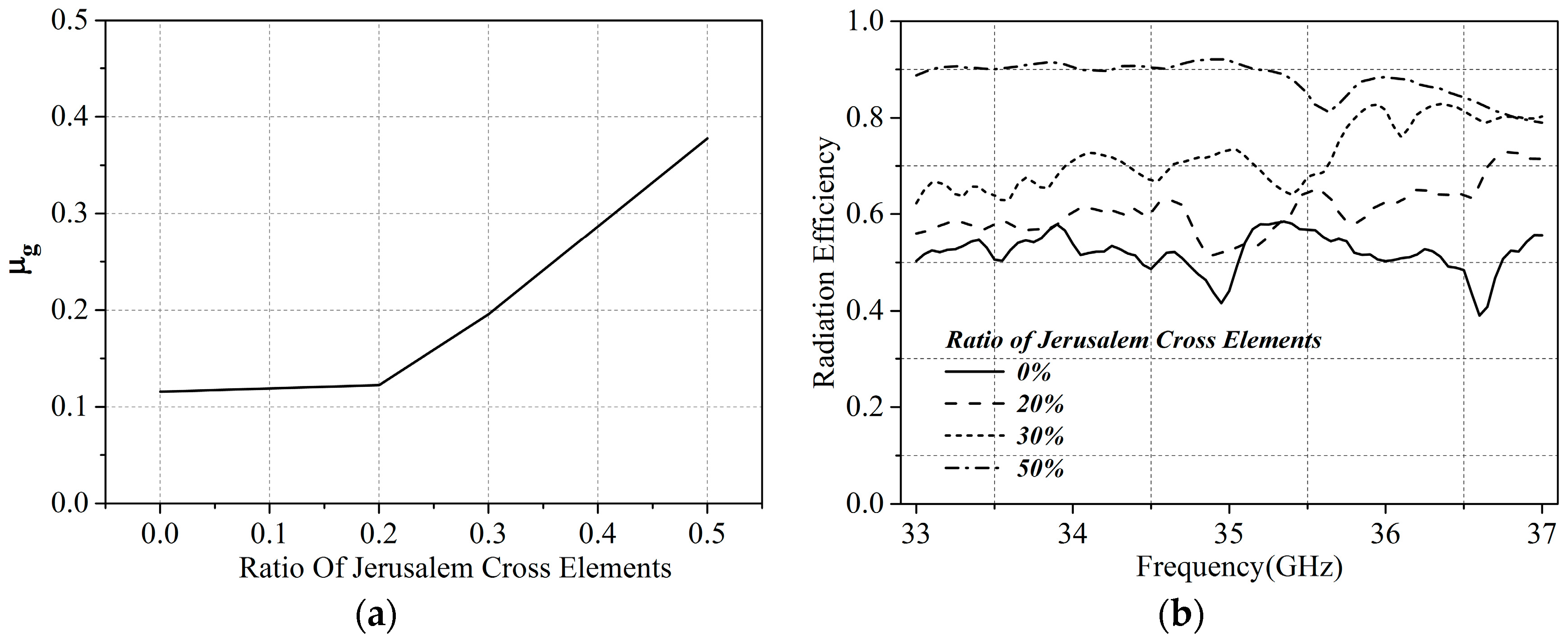
When the filling ratio of CJC elements on the MAA is changed from 0 to 50%, as shown in Figure 6, the average mutual coherence μg will vary from 0.115 to 0.377, as shown in Figure 7a. The radiation efficiency of the MAAs with different ratios of CJC elements is shown in Figure 7b. We can see in Figure 7 that the increase in radiation efficiency causes μg to increase. As a result, to obtain a relatively high radiation efficiency and a low μg, the ratio of CJC elements must be selected as 20% since its radiation efficiency has been improved to around 60% and its capability of imaging reconstruction approaches that of a metamaterial aperture without CJC elements.
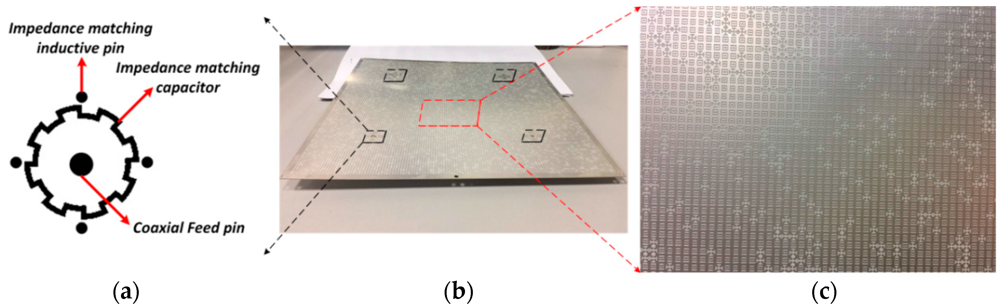
Thus, the prototype of a metamaterial aperture antenna, with 120 × 120 randomly distributed CELC and CJC elements, whose total size is 250 mm × 250 mm × 0.5 mm was fabricated, measured, and analyzed. The fabricated MAA consisted of 80% CELC elements and 20% CJC elements, as shown in Figure 8b,c. The feed structure of the metamaterial aperture antenna is shown in Figure 8a below. The array consists of four uniform feed structures. The feed structure contains one impedance matching capacitor and four impedance matching inductive pins, and a coaxial feed pin is at the center of the structure. The measurement was performed using near-field planar-scanning techniques and near-to-far-field transformation [20]. The measured far-field patterns across the frequency band from 33 to 37 GHz are shown in Table 1. It can be seen that the designed MAA has frequency-diverse far-field patterns.
5. Discussion
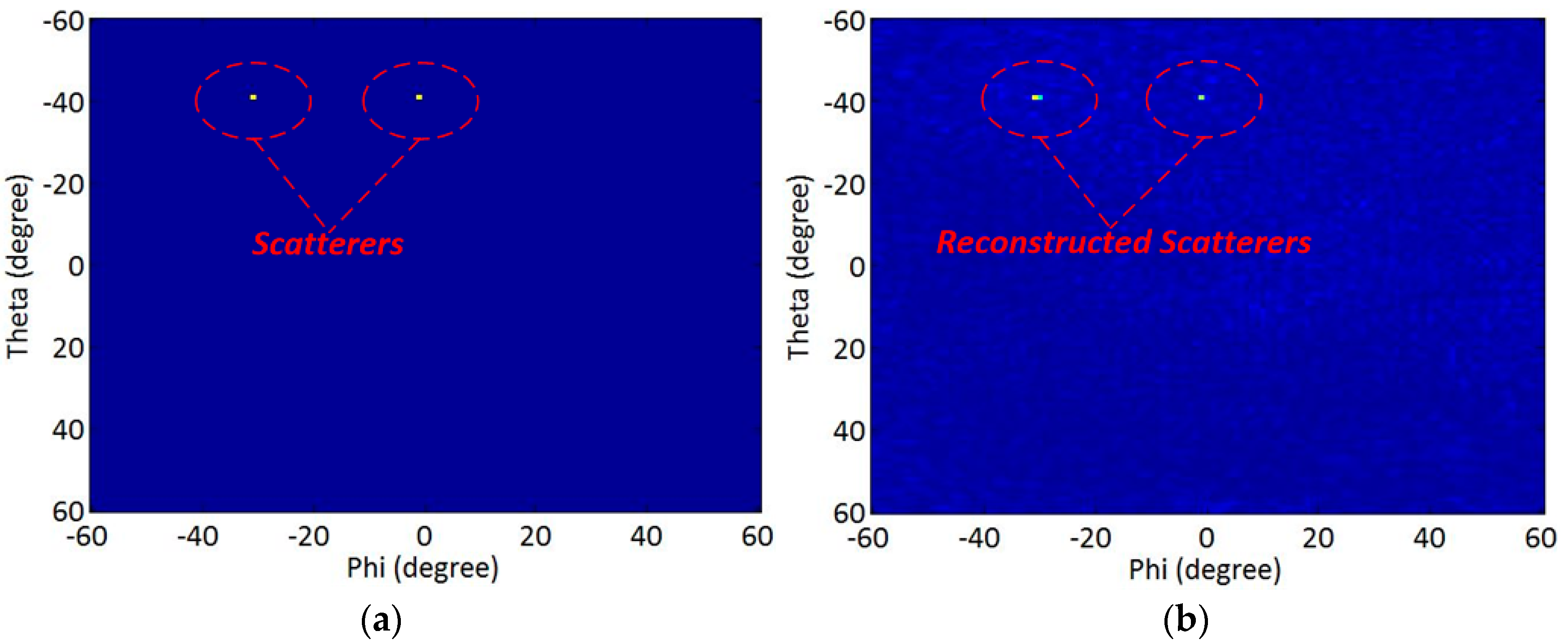
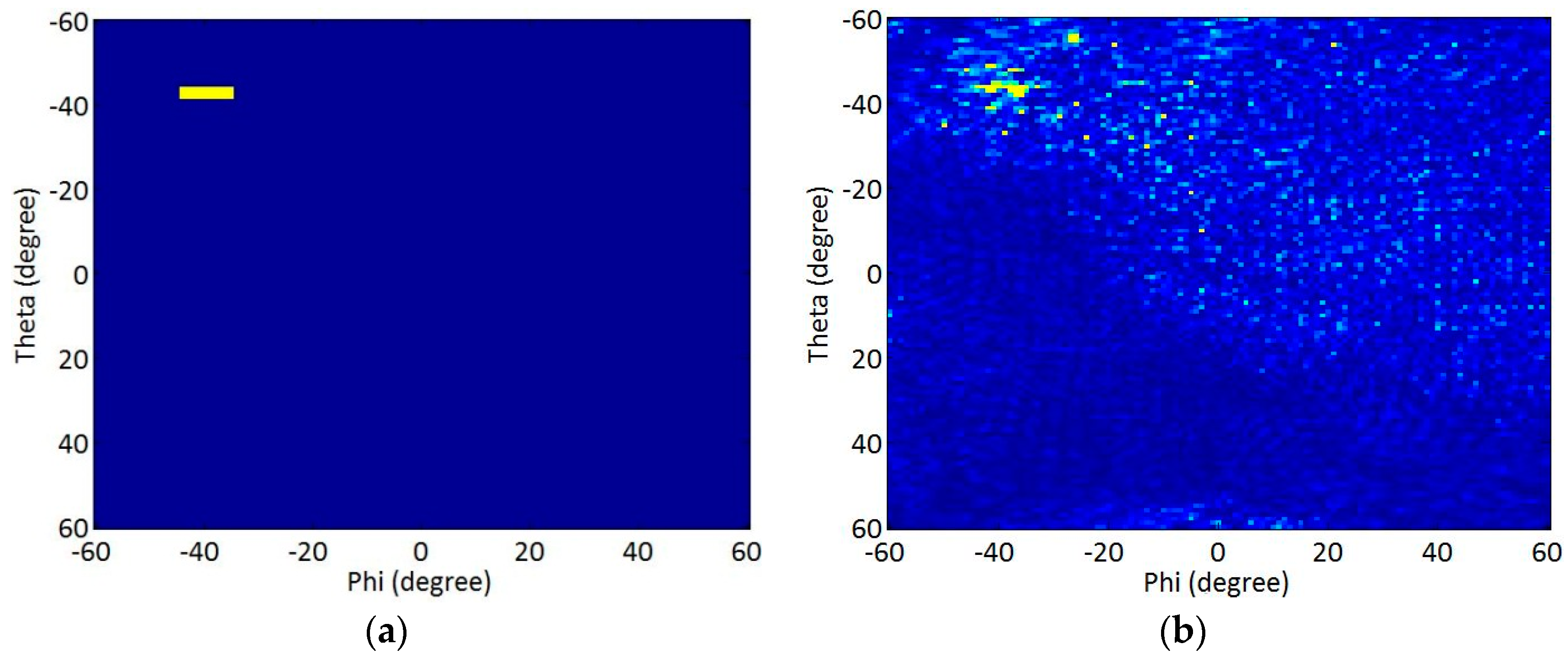
The capability of imaging reconstruction of the fabricated metamaterial aperture antenna was explored based on the measured data. The specific parameters of the MAA’s coherent computational imaging system are shown in Table 2. Figure 9a shows the original sparse target scene, which includes two scatterers, and Figure 9b shows this scene reconstructed via the pseudo-inverse method. It can be seen in Figure 9 that the designed MAA could be effectively used to reconstruct the target scenes. In conclusion, when using the complementary electric-field-coupled (CELC) element and the complementary Jerusalem cross (CJC) element with a random distribution ratio of 4 to 1, the radiation efficiency of the MAA can achieve 60%, and the far-field patterns has good orthogonality, which could be effectively used to reconstruct the target scatterers scene.
Since the capability of imaging reconstruction of the fabricated metamaterial aperture antenna is explored based on the measured far-field data, the range of the target is in the far-field region. In this case, since the dimension of the fabricated metamaterial aperture antenna is 250 mm × 250 mm × 0.5 mm, and the center frequency is 35 GHz, the far-field region is r ≥ (2 × 0.25 m × 0.25 m)/λ0 = 14.5 m (λ0 is the wavelength at the center frequency in free space). As a result, the true target is assumed to be 15 m away from the metamaterial aperture antenna.
The capability of imaging reconstruction of the new proposed metamaterial aperture antenna was determined based on simulated targets at the present stage [21]. As for larger targets, we also employed a simulated metal sheet target to validate the capability of imaging reconstruction of the new proposed MAA, as shown in Figure 10 below. In Figure 10, we can see that the measured far-field data could be used to reconstruct the location and shape of the metal sheet more precisely, but not perfectly. Going forward, more practical experiments with a more precise reconstruction of larger targets will be crucial.
6. Conclusions
A new metamaterial aperture antenna (MAA) composed of two kinds of metamaterial elements with random distribution was proposed, designed, and measured to perform compressive image reconstruction. One element has a high Q-value with an agile frequency response, and the other element has a relatively low Q-factor and has a high radiation efficiency. The orthogonality of the far-field patterns and the improvement in the radiation efficiency of the MAA were theoretically analyzed. Numerical simulations and measurements show that the radiation efficiency of the MAA can achieve 60%, and the far-field patterns have good orthogonality; the MAA can therefore be effectively used to reconstruct scenes with target scatterers when using the complementary electric-field-coupled (CELC) element and the complementary Jerusalem cross (CJC) element with a random distribution ratio of 4 to 1. Moreover, the proposed MAA can be effectively used for coherent computational imaging.
Acknowledgments
This work was supported by the National Natural Science Foundation of China under Contract No. 51477126, the Technology Explorer and Innovation Research Project, and Fundamental Research Funds for the Central Universities (K5051202051 and SPSZ021409).
Author Contributions
Na Kou conceived the idea of improving the radiation efficiency of the metamaterial aperture antenna and performed the simulations and experiments; Long Li provided the main instructions of the ideas and experiments; Shuncheng Tian and Yuanchang Li designed the feed of the antenna and performed the experiments.
Conflicts of Interest
The authors declare no conflict of interest. The founding sponsors had no role in the design of the study; in the collection, analyses, or interpretation of data; in the writing of the manuscript; or in the decision to publish the results.
References
- Hunt, J.; Driscoll, T.; Mrozack, A.; Lipworth, G.; Reynolds, M.; Brady, D.; Smith, D.R. Metamaterial apertures for computational imaging. Science 2013, 339, 310–313. [Google Scholar] [CrossRef] [PubMed]
- Brady, D.J.; Choi, K.; Marks, D.L.; Horisaki, R.; Lim, S. Compressive holography. Opt. Express 2009, 17, 13040–13049. [Google Scholar] [CrossRef] [PubMed]
- Cull, C.F.; Wikner, D.A.; Mait, J.N.; Mattheiss, M.; Brady, D.J. Millimeter-wave compressive holography. Appl. Opt. 2010, 49, 67–82. [Google Scholar] [CrossRef] [PubMed]
- Lohmann, A.W.; Testorf, M.E.; Ojeda-Castañeda, J. The space-bandwidth product, applied to spatial filtering and to holography. Med. J. Aust. 2006, 1, 565. [Google Scholar]
- Marks, D.L.; Gollub, J.; Smith, D.R. Spatially resolving antenna arrays using frequency diversity. J. Opt. Soc. Am. A 2016, 33, 899–912. [Google Scholar] [CrossRef] [PubMed]
- Sleasman, T.; Imani, M.F.; Gollub, J.N.; Smith, D.R. Microwave Imaging Using a Disordered Cavity with a Dynamically Tunable Impedance Surface. Phys. Rev. Appl. 2016, 6, 054019. [Google Scholar] [CrossRef]
- Sleasman, T.; Boyarsk, M.; Imani, M.F.; Gollub, J.N.; Smith, D.R. Design considerations for a dynamic metamaterial aperture for computational imaging at microwave frequencies. J. Opt. Soc. Am. B 2016, 33, 1098. [Google Scholar] [CrossRef]
- Fromenteze, T.; Yurduseven, O.; Imani, M.F.; Gollub, J.; Decroze, C.; Carsenat, D.; Smith, D.R. Computational imaging using a mode-mixing cavity at microwave frequencies. Appl. Phys. Lett. 2015, 106, 194104. [Google Scholar] [CrossRef]
- Fromenteze, T.; Decroze, C.; Carsenat, D. Waveform Coding for Passive Multiplexing: Application to Microwave Imaging. IEEE Trans. Antennas Propag. 2014, 63, 593–600. [Google Scholar] [CrossRef]
- Sleasman, T.; Imani, M.F.; Gollub, J.N.; Smith, D.R. Dynamic metamaterial aperture for microwave imaging. Appl. Phys. Lett. 2015, 107, 204104. [Google Scholar] [CrossRef]
- Guariglia, E. Entropy and Fractal Antennas. Entropy 2016, 18, 84. [Google Scholar] [CrossRef]
- Guariglia, E. Fractional Derivative of the Riemann Zeta Function. Fract. Dyn. 2015, 21, 357–368. [Google Scholar]
- Lipworth, G.; Mrozack, A.; Hunt, J.; Marks, D.L.; Driscoll, T.; Brady, D.; Smith, D.R. Metamaterial microwave holographic imaging system. J. Opt. Soc. Am. A 2013, 30, 1603. [Google Scholar] [CrossRef] [PubMed]
- Lipworth, G.; Rose, A.; Yurduseven, O.; Gowda, V.R.; Imani, M.F.; Odabasi, H.; Trofatter, P.; Gollub, J.; Smith, D.R. Comprehensive simulation platform for a metamaterial imaging system. Appl. Opt. 2015, 54, 9343–9353. [Google Scholar] [CrossRef] [PubMed]
- Schurig, D.; Mock, J.J.; Smith, D.R. Electric-field-coupled resonators for negative permittivity metamaterials. Appl. Phys. Lett. 2006, 88, 041109. [Google Scholar] [CrossRef]
- Arnaud, J.A.; Pelow, F.A. Resonant-Grid Quasi-Optical Diplexers. Electron. Lett. 1973, 9, 589–590. [Google Scholar] [CrossRef]
- Duarte-Carvajalino, J.M.; Sapiro, G. Learning to sense sparse signals: Simultaneous sensing matrix and sparsifying dictionary optimization. IEEE Trans. Image Process. 2009, 18, 1395–1408. [Google Scholar] [CrossRef] [PubMed]
- Elad, M. Optimized Projections for Compressed Sensing. IEEE Trans. Signal Process. 2007, 55, 5695–5702. [Google Scholar] [CrossRef]
- Chu, L.J. Physical Limitations of Omni-Directional Antennas. J. Appl. Phys. 1948, 19, 1163–1175. [Google Scholar] [CrossRef]
- Balanis, C.A. Antenna Theory: Analysis and Design, 3rd ed.; Wiley-Interscience: Hoboken, NJ, USA; Harper & Row: Bel Air, CA, USA, 2005; pp. 1014–1026. [Google Scholar]
- Wu, Z.; Zhang, L.; Liu, H.; Kou, N. Enhancing Microwave Metamaterial Aperture Radar Imaging Performance with Rotation Synthesis. IEEE Sens. J. 2016, 16, 8035–8043. [Google Scholar] [CrossRef]
Figure 1.
A metamaterial aperture illuminating a human target scene.

Figure 2.
Flow chart of the μg analysis procedure.

Figure 3.
Comparison of the average mutual coherence μg between phase and amplitude modulation.

Figure 4.
The complementary electric-field-coupled (CELC) element with a unit cell size of 2 mm: (a) full-wave simulation model; (b) its top view; (c) the variation in radiation efficiency when l and g change.
Figure 4.
The complementary electric-field-coupled (CELC) element with a unit cell size of 2 mm: (a) full-wave simulation model; (b) its top view; (c) the variation in radiation efficiency when l and g change.

Figure 5.
(a) Top view of complementary Jerusalem cross (CJC) element with a unit cell size of 2 mm and (b) a radiation efficiency of the element.
Figure 5.
(a) Top view of complementary Jerusalem cross (CJC) element with a unit cell size of 2 mm and (b) a radiation efficiency of the element.

Figure 6.
The schematic of simulated metamaterial aperture antenna (MAA) with different ratios of CJC elements: (a) 0%; (b) 20%; (c) 50%.
Figure 6.
The schematic of simulated metamaterial aperture antenna (MAA) with different ratios of CJC elements: (a) 0%; (b) 20%; (c) 50%.

Figure 7.
(a) Calculated average mutual coherence μg and (b) the radiation efficiency of different MAAs with different filling ratios of CJC elements.
Figure 7.
(a) Calculated average mutual coherence μg and (b) the radiation efficiency of different MAAs with different filling ratios of CJC elements.

Figure 8.
Geometry of the fabricated MAA: (a) feed structure (the black capacitor part is dielectric, and the remaining part is copper); (b) total view; (c) local view.
Figure 8.
Geometry of the fabricated MAA: (a) feed structure (the black capacitor part is dielectric, and the remaining part is copper); (b) total view; (c) local view.

Figure 9.
Target scenes: (a) true target scene consisting of two point scatterers; (b) the same scene reconstructed by the fabricated MAA.
Figure 9.
Target scenes: (a) true target scene consisting of two point scatterers; (b) the same scene reconstructed by the fabricated MAA.

Figure 10.
Target scenes: (a) true target scene consisting of one metal sheet scatterers; (b) the same scene reconstructed by the fabricated MAA.
Figure 10.
Target scenes: (a) true target scene consisting of one metal sheet scatterers; (b) the same scene reconstructed by the fabricated MAA.


Table 1.
Measured field patterns of the metamaterial aperture antenna at different frequencies.
| 33 GHz | 33.5 GHz | 34 GHz |
 |  |  |
| 34.5 GHz | 35 GHz | 35.5 GHz |
 |  |  |
| 36 GHz | 36.5 GHz | 37 GHz |
 |  |  |
Table 2.
System parameters of the metamaterial aperture antenna.
| Parameters | Value |
|---|---|
| Field of View(Elevation) | −60–60° |
| Frequency sampling interval | 0.1 GHz |
| Elevation sampling interval | 1° |
| Azimuth sampling interval | 1° |
© 2017 by the authors. Licensee MDPI, Basel, Switzerland. This article is an open access article distributed under the terms and conditions of the Creative Commons Attribution (CC BY) license (http://creativecommons.org/licenses/by/4.0/).
Share and Cite
MDPI and ACS Style
Kou, N.; Li, L.; Tian, S.; Li, Y. Measurement Matrix Analysis and Radiation Improvement of a Metamaterial Aperture Antenna for Coherent Computational Imaging. Appl. Sci. 2017, 7, 933. https://0-doi-org.brum.beds.ac.uk/10.3390/app7090933
AMA Style
Kou N, Li L, Tian S, Li Y. Measurement Matrix Analysis and Radiation Improvement of a Metamaterial Aperture Antenna for Coherent Computational Imaging. Applied Sciences. 2017; 7(9):933. https://0-doi-org.brum.beds.ac.uk/10.3390/app7090933
Chicago/Turabian StyleKou, Na, Long Li, Shuncheng Tian, and Yuanchang Li. 2017. "Measurement Matrix Analysis and Radiation Improvement of a Metamaterial Aperture Antenna for Coherent Computational Imaging" Applied Sciences 7, no. 9: 933. https://0-doi-org.brum.beds.ac.uk/10.3390/app7090933
Note that from the first issue of 2016, this journal uses article numbers instead of page numbers. See further details here.