Application of a Coupled Eulerian-Lagrangian Technique on Constructability Problems of Site on Very Soft Soil

1
Department of Civil, Environmental, and Construction Engineering, Texas Tech University, Lubbock, TX 79409, USA
2
Department of Civil and Environmental Engineering, Yonsei University, Seoul 03722, Korea
*
Author to whom correspondence should be addressed.
Appl. Sci. 2017, 7(10), 1080; https://0-doi-org.brum.beds.ac.uk/10.3390/app7101080
Submission received: 29 September 2017
/
Revised: 12 October 2017
/
Accepted: 13 October 2017
/
Published: 18 October 2017
Abstract
:This paper presents the application of the Coupled Eulerian–Lagrangian (CEL) technique on the constructability problems of site on very soft soil. The main objective of this study was to investigate the constructability and application of two ground improvement methods, such as the forced replacement method and the deep mixing method. The comparison between the results of CEL analyses and field investigations was performed to verify the CEL modelling. The behavior of very soft soil and constructability with methods can be appropriately investigated using the CEL technique, which would be useful tools for comprehensive reviews in preliminary design.
1. Introduction
Recently, South Korea has seriously lacked the land space because of the increase with the population density and industrialization, thus a number of constructions such as the housing complex, high-speed railway, international airport, and harbor construction are progressing in soft soil areas located in coastal area.
Especially, organic soils are widely distributed over the world, including South Korea, Japan, Australia, Malaysia, and Canada. The area of organic soils is approximately 2.3 million km2. Whitlow [1] reported that the organic soil deposits have occurred on the Gold Coast region, Australia, because of current and past marine processes near coastal zones. Also, Malaysia has organic soil deposits observed mainly along the coastal area [2]. According to the Unified Soil Classification System [3], organic soils can be classified as organic clay (OL), organic silt (OH), and peat (Pt). Especially, organic soils can be defined as one with a minimum of 50% organic matter. Organic soils have typically low unit weight, high water contents, high content of organic matter, and high compressibility [4]. The high compressibility of organic soils leads to the increases of risk under the constructions, such as excavations, foundations, and embankments. Therefore, if the structure or embankment are constructed on the organic soils, it cannot be ensured the safety of structure because of the large deformation and low bearing capacity. Hence, it is difficult to predict the behavior of organic soils, thus encountering significant challenges in the preliminary design stage. Therefore, a proper technique for large deformation analysis is necessary to investigate the behavior and safety of the structures on very soft soil, such as organic soil.
Many studies have been performed to solve the geotechnical problems using numerical techniques, especially the finite element method (FEM). However, it has limitations to solve those, including large deformation between soil-structure or soil-soil interactions using traditional numerical methods, since most researches have been based on the Lagrangian coordinates for the small deformation analysis. For the finite element methods based on the Lagrangian coordinates, the large deformation may lead to the problems, including the mesh and the unconvergence divergence due to severe relative displacement.
Recently, a Coupled Eulerian-Lagrangian (CEL) technique has been developed to overcome the limitations of the small deformation analyses. This technique has been applied to various geotechnical fields, such as the penetration of offshore structure [5,6,7,8,9], the landslide and debris flow [10,11], the pile penetration [12,13,14,15,16], and the effect on the nearby soil due to tunneling [17].
The overall objective of this study is to investigate the behavior and safety of the structures on very soft soil such as organic soil, accounting for the application and constructability of ground improvement methods, including forced replacement method and deep mixing method. The large deformation finite element (LDFE) analyses are carried out using the Coupled Eulerian-Lagrangian technique. For CEL modelling validation, the results of CEL analyses in this study are compared with field investigations with settlement, height, and range of soil heave. Additionally, to examine the constructability and economics of each method, comprehensive reviews are performed.
2. Project Description
In this study, the construction site on very soft clay is targeted in Gangeung-si, South Korea, located in along the coastal area. Figure 1 shows the location of the study area in South Korea.
2.1. Review of Previous Studies
To understand the reliable geotechnical characteristics in this site, the literature review about a nearby area is conducted. Yeongdong area is located along the shoreline of the East Sea in South Korea, thus this area has the low temperature in summer, high temperature in winter, and high average annual rainfall, leading to be a suitable conditions for the formation of the peat deposit.
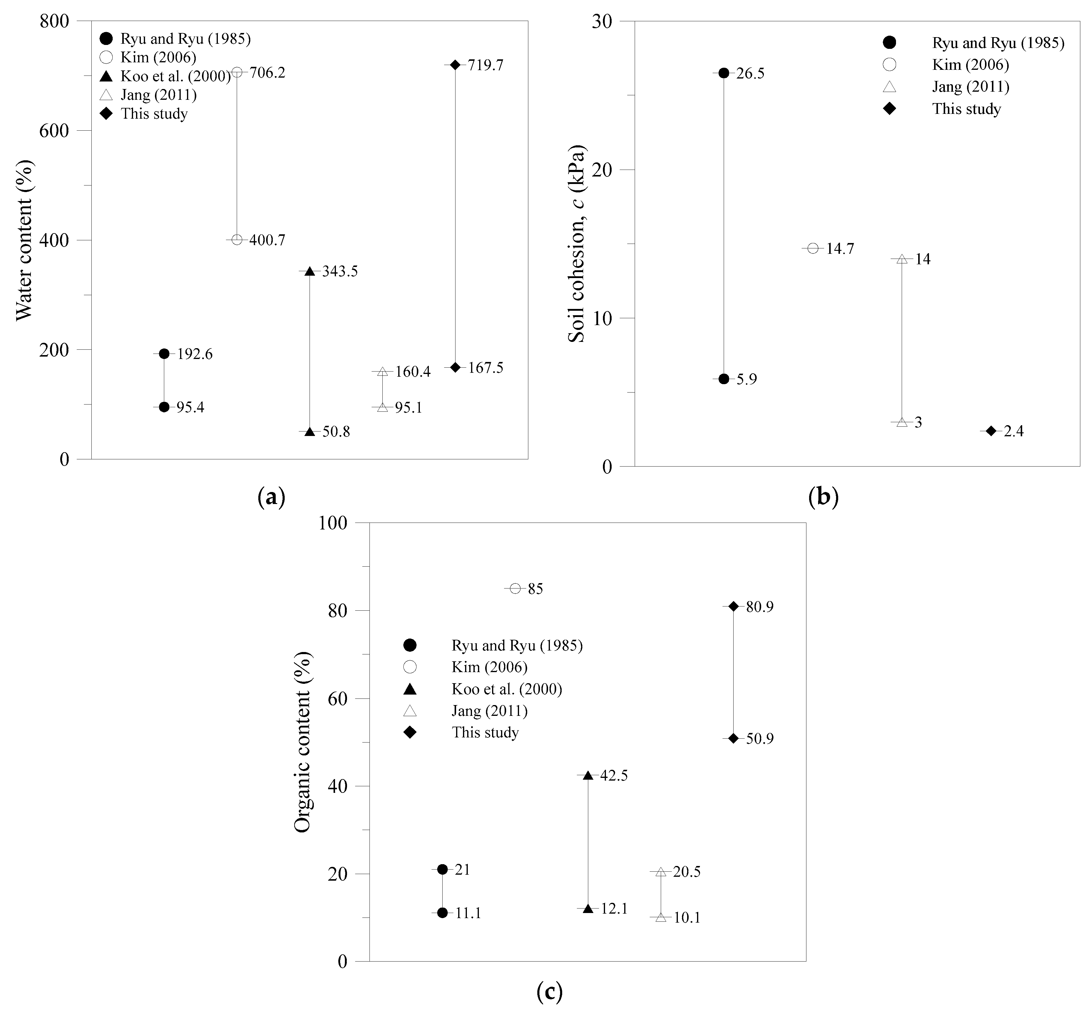
Kim [18] reported the case study of construction on the peat deposits, which had the water contents of 400.7%–706.2%, the unit weight of 9.7–10.6 kN/m3, and the organic contents of 85%. Ryu and Ryu [19] described in their paper that the peat deposits had the water contents ranged from 95.4 to 192.6%, and the organic contents varied from 11.1 to 21.0%. Koo et al. [20] reported that the peat deposits had the water contents ranged between 50.8% and 343.5%, and the organic contents varied from 12.1 to 42.5%. Jang [21] reported that the organic soil was distributed over 0.5 km2 in the Yeongdong area. In addition, the characteristics of organic soil in Sokcho, Yangyang, and Gangneung area were reported in Table 1.
2.2. Geotechnical Investigation
Figure 2 illustrates the soil profiles in this site. Based on the borehole survey, subsurface profile consisted of a peat (Pt) deposit and clay of high plasticity, fat clay (CH) deposit from the ground surface to a depth of 16.0 m. The standard penetration number (N value) of the deposits from 0.0 to 16.0 m are 0/30, indicating a very soft soil condition. In case of the peat, it is impossible to work for any construction without additional ground improvement.
Based on the geotechnical investigation, for the peat, the water contents range from 167.5 to 719.7%. The standard penetration number (N value) of the peat range from 0/30 to 1/30. The elastic modulus (Es), the soil cohesion (c), and the unit weight (γ) of the peat are 240 kPa, 2.4 kPa, and 10–11 kN/m3, respectively. Also, the organic contents range from 50.9 to 80.9%.
The geotechnical properties of this site are compared with those of previous studies, as shown in Figure 3. The organic contents and water contents of this site are larger than those of the previous studies, as shown in Figure 3a,c, whereas the soil cohesion of this site has the lowest value among other cases. Hence, these geotechnical characteristics are far worse than not only the typical strength and stiffness but also organic contents and water contents of nearby area. It was even impossible to obtain the specimen and sampling for the laboratory tests in some area. Based on the geotechnical investigations, it is found that the peat deposit had ‘very extremely soft conditions’, like a fluid.
The representative problems related to the construction are the significant total settlement and differential settlement caused by the low strength and the high compressibility of very soft soil, such as organic soil. The organic soil under the external loading may be largely deformed, such as the immediately settlement, since the nearby organic soil without the external loading can hardly have the lateral resistance. Hence, the lateral deformation and the heave in nearby very soft soil may occur, and the failure may follow eventually. Therefore, for the installation and construction of structures on the very soft soil, it is necessary to investigate the safety of construction procedure and method appropriately in preliminary design stage, ensuring the application and constructability.
3. Ground Improvement Methods
Not only the safety of structure during use, but also that during construction is very important, thus, the construction procedure and methods should be considered whether those are proper or not. Especially, the constructions of structures on very soft soil may have unexpected problems such as the poor constructability, unexpected increase in costs, and accidents. Two ground improvement methods, such as (1) forced replacement method, and (2) deep mixing method, have been actually planned in the design stage for a practical field. Thus, the applicability of two ground improvement methods is examined using the CEL in the design stage.
3.1. Forced Replacement Method
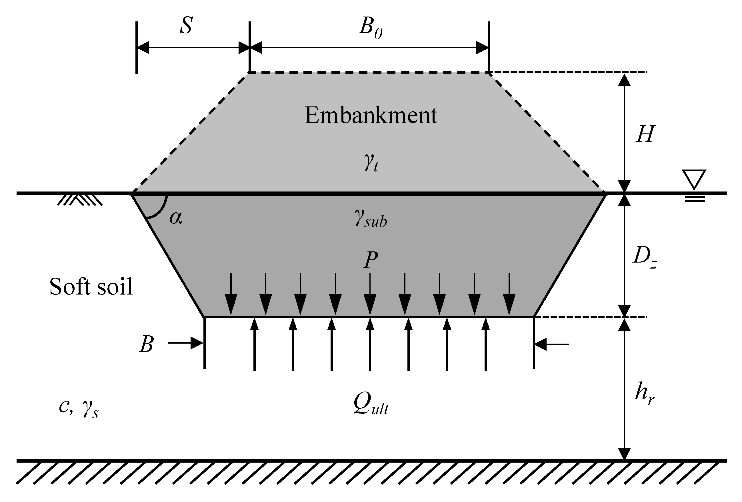
Firstly, the forced replacement method has advantages such as the low cost and the simple method. On the other hand, if this method applied for the very soft soil such as organic soil, the shear failure, the significant heave and settlement may occur. The concept of this method is that the very soft subsoil is replaced by the materials of good quality, which have the high strength and unit weight, such as sand and broken rock, leading to improve the ground strength. Figure 4 illustrates the schematic diagram of the forced replacement method.
It is basically assumed that the embankment unit load p is equal to the unit ultimate bearing stress of soft soil qult. The embankment unit load p can be estimated as follows:
where H = height of embankment; γt = unit weight of embankment; Dz = replacement depth; and, γsub = effective unit weight of embankment.
p = Hγt + Dzγsub
Many researchers recommended the replacement depth Dz based on the limit equilibrium method. According to Terzaghi [22], the replacement depth Dz using Nc value of 5.7 can be written as
where c = soil cohesion; γs = unit weight of soft soil (original soil).
Yasuhara and Tsukamoto [23] suggests the replacement depth Dz using Nc value of 5.3 can be estimated as
Lee [24] reported the equation to estimate the replacement depth Dz using Nc value of 5.14 as follows:
These existing methods can predict the replacement depth simply and indirectly, however, those can not predict the height and influence range of heave soil that would be required in design and construction stage.
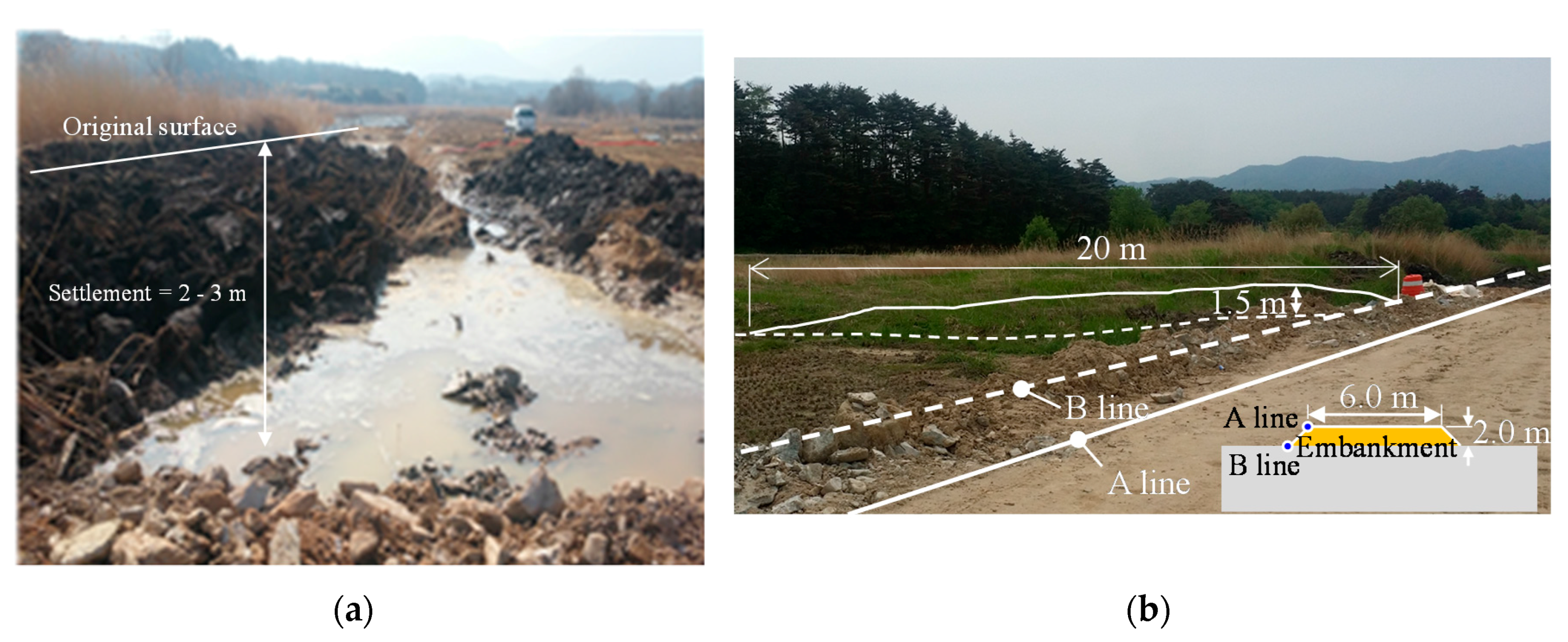
For this site, the field test was conducted to review the constructability of the forced replacement method. The replacement depth, settlement, and soil heave were investigated. The width and height of embankment for field test were 6.0 m and 2.0 m, respectively. The settlement of embankment was measured by using the survey and visual observation. In this site, we confirmed that the entire embankment was settled to the subsurface in a day, thus, we regarded it as a ‘punch failure’ or ‘forced replacement’. Based on the investigation, the settlement was about from 2.0 to 3.0 m, hence, we could predict the replacement depth of 4.0–5.0 m because of the sum of the settlement and the height of embankment. Also, the soil heave near the embankment occurred. The range and height of soil heave were measured by using the visual observation. The range and height of soil heave were 20 and 1.5 m, respectively, as shown in Figure 5. Especially, the soil heave influenced the nearby agricultural land, thus the damage occurred.
The replacement depths in this case are estimated using the theoretical existing methods, and are compared with the results of field test. As mentioned above, the entire embankment in this site was settled to the subsurface, thus, the height of embankment is zero when the replacement depth is estimated using existing methods. The replacement depths estimated by Terzaghi [22], Yasuhara, Tsukamoto [23], and Lee [24] represents 1.95, 1.91 and 1.85 m, respectively. When compared with the field investigations, it is shown that estimated replacement depths from existing methods are underestimated. Additionally, the influence range and height of heave soil cannot be estimated using the existing methods. The existing methods have the limitations because those are based on the limit equilibrium method.
3.2. Deep Mixing Method
Secondly, the deep mixing methods of soil stabilization is a ground improvement technique, which increases the soil strength by mixing them with cementitious material. Therefore, it is necessary to investigate the safety for the construction procedure and method appropriately.
In this study, the large deformation analysis are conducted to investigate the adequacy of the forced replacement methods. In addition, for the deep mixing methods, we study the safety caused by the increasing self-weight, and the constructability for pile installation, including the self-standing of pile equipment, the effect of pile jacking, and pile driving.
4. CEL Modelling
The Coupled Eulerian-Lagrangian technique in ABAQUS/Explicit [25] is employed to investigate the constructability and application of two ground improvement methods, such as the forced replacement method and deep mixing method. Especially, in the case of the deep mixing method, the safety of pile installation on soil, which is treated in the deep mixing method, is studied.
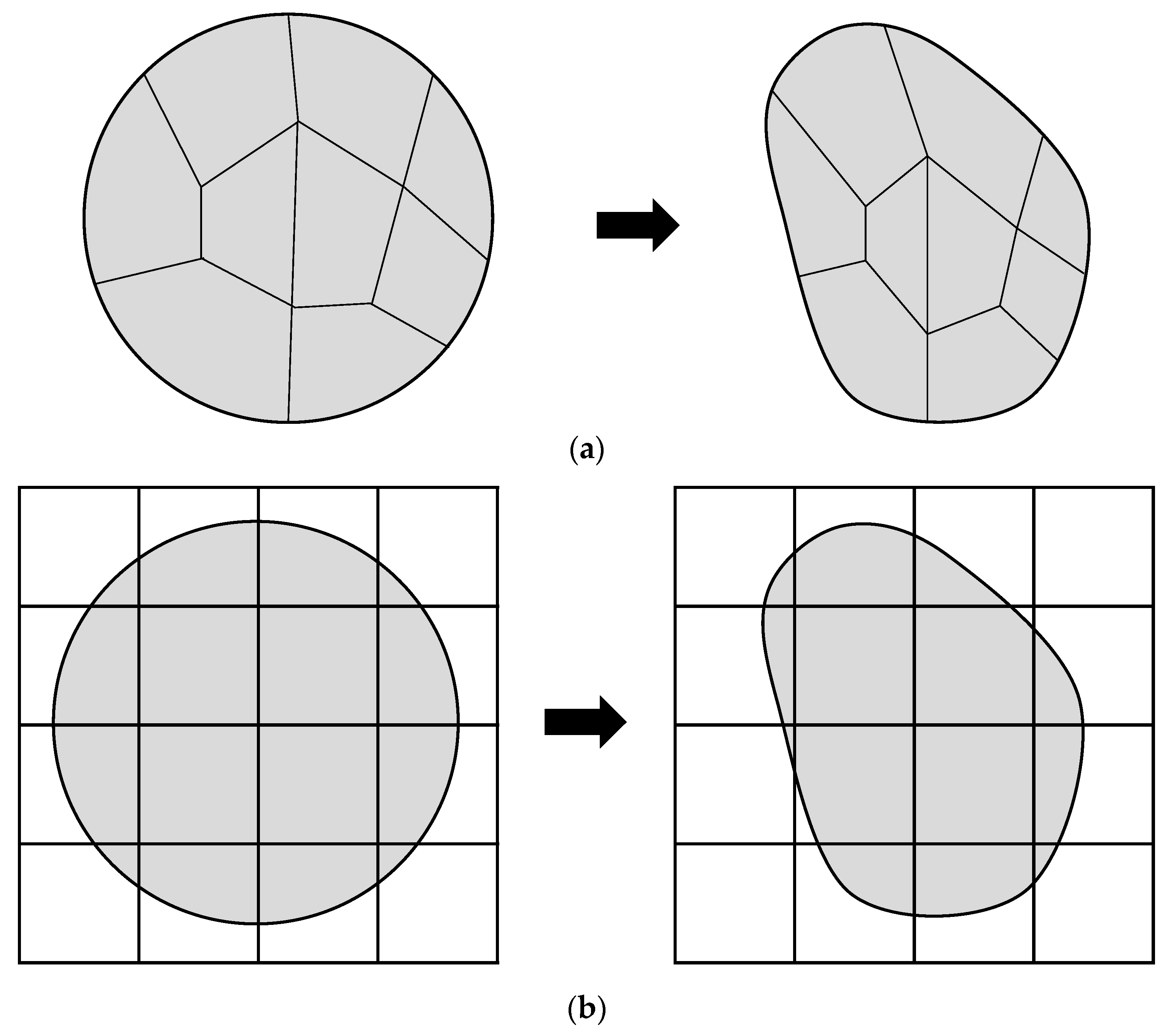
The CEL technique has the advantages both of the Lagrangian and the Eulerian coordinate is implemented in ABAQUS [25]. The materials for Lagrangian coordinate that is typically applied in solid mechanics could not undergo significant deformation, whereas the materials for Eulerian coordinate, which is applied in fluid mechanics could experience large displacements. Figure 6 shows the deformation of a continuum in a Lagrangian and an Eulerian analysis. The Lagrangian analysis is based on the movement of each node and element under the external force, on the other hand, the Eulerian analysis is based on the concept that the node and element are fixed, and the materials flow through the elements of fixed mesh under the external force. Therefore, re-meshing is not required and severe mesh distortion causing numerical instability cannot occur in a CEL analysis [5].
In this CEL analysis, the contact between Eulerian and Lagrangian materials is applied using a general contact algorithm, which is performed by tracking and capturing between two surfaces. Hence, the master surface can track nodes of slave surface using a contact algorithm in ABAQUS [25]. The behavior of interface is applied by using the penalty contact method based on the Coulomb’s frictional model. Especially, for simulation of pile installation on deep mixing soil, the friction coefficient μ for soil-concrete pile and soil-pile driver interface generally are 0.3 [26,27], thus, the friction coefficient of 0.3 is adopted in this study. In addition, the limiting shear stress is applied to be equal to the soil cohesion. The initial equilibrium state is important, thus the geostatic stress is implemented in a predefined step to consider the initial equilibrium state. The geostatic stress is generated by taking the coefficient of earth pressure at rest, K0 = 1. The present analysis is conducted in sequence according to ‘initial-gravity-loading’. It means that the initial stress field like ‘geostatic’ state can be imposed. The elements of Lagrangian and Eulerian domains consist of 8-noded Lagrangian brick elements (C3D8R) and 8-noded Eulerian brick elements (EC3D8R).
4.1. Mesh Convergence Study
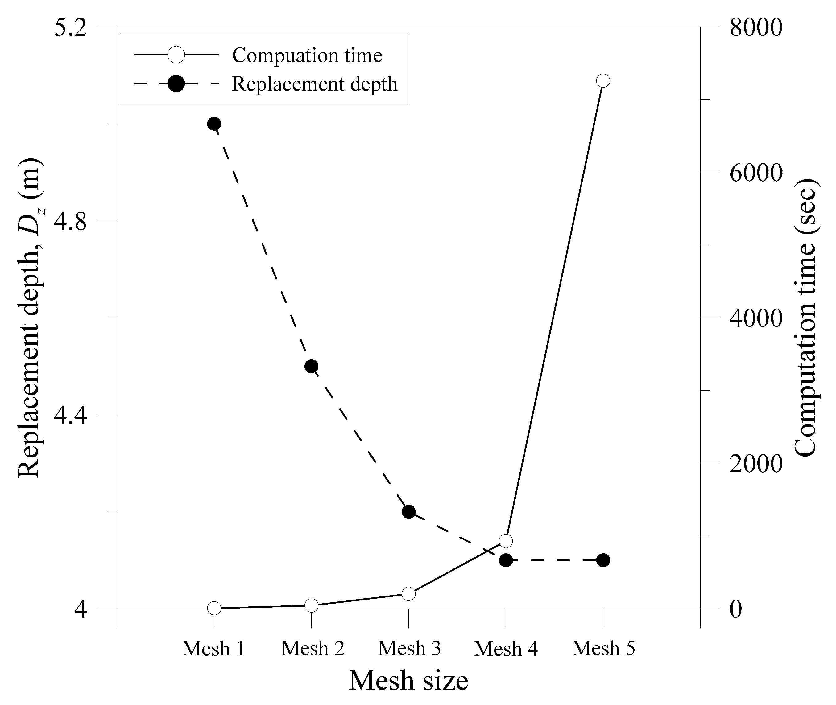
The mesh convergences study is necessary to investigate the suitable mesh size for accurate results and computational efficiency. For the mesh convergences study, the forced replacement method is simulated. The input parameters for the mesh convergence study are summarized in Table 2. The height of embankment of 2.0 m is adopted in mesh convergence studies, and the distance from surface to replacement is identified in terms of mesh sizes sm. In this study, five different mesh sizes are assumed with the ratios between the mesh size and the width of embankment (sm/B0) of 0.0833, 0.0417, 0.0167, 0.0083 and 0.0042. Here, the mesh size increases from Mesh 5 to Mesh 1, in other words, the mesh density increases from Mesh 1 to Mesh 5. Table 3 indicates the summary of the mesh convergence studies. Figure 7 shows the relationship between replacement depth and computation time with mesh sizes. The replacement depths of Mesh 4 are identical with that of Mesh 5, also the computation time of Mesh 5 is dramatically increased. It is demonstrated that the mesh size of Mesh 4 reaches the convergence, therefore, Mesh 4 is used for all of CEL analyses.
4.2. Simulation of Forced Replacement Method
As mentioned above, the subsurface deposit from 0.0 to 16.0 m consists of very soft soil, having SPT N value of 0/30. Thus, it was planned to improve a soil strength through the forced replacement method in this site, in order to build the temporary road embankment for the construction. For the forced replacement method, the lateral deformation and the heave in nearby the range occurring forced replacement would occur together. These effects are closely related to the constructability and economics for construction. However, the existing approaches for replacement depth could not predict the height and range of soil heave. Therefore, the CEL analyses are performed to investigate the replacement depth, height and range of soil heave of this site.
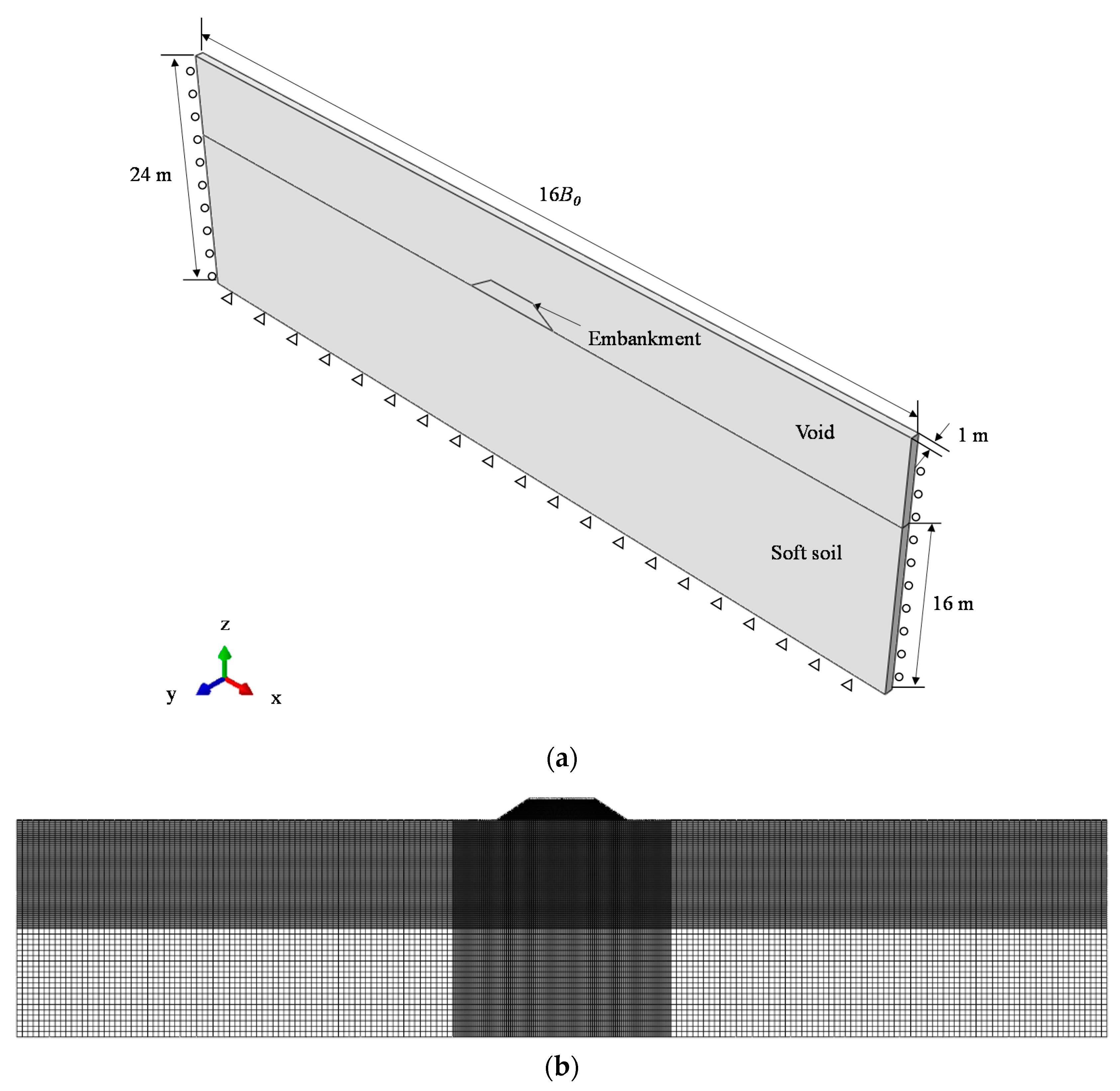
Figure 8 shows a CEL model for the simulation of forced replacement method. The overall dimensions of the domains comprise a width of 16 times the embankment width (B0) in x-direction, in order to minimize possible boundary effect on the predicted replacement depth, height, and range of soil heave. In addition, the width of the domain in y-direction is 1 m, because the replacement depth and soil heave are mainly important in this analysis. The height of the domains in z-direction is 16.0 m, and the width and height of embankment are modelled on 6.0 m and 2.0 m, respectively, which is identical with the site condition. Zero horizontal displacements are predefined at the lateral boundaries and full fixities at the bottom boundary. The domain is divided into two parts, i.e., the soft soil part and the void part where the soil could be heaved and moved into the empty element. Especially, the void part have no properties, indicating zero strength and stiffness. The input parameters for analyses are summarized in Table 2, based on the geotechnical investigation.
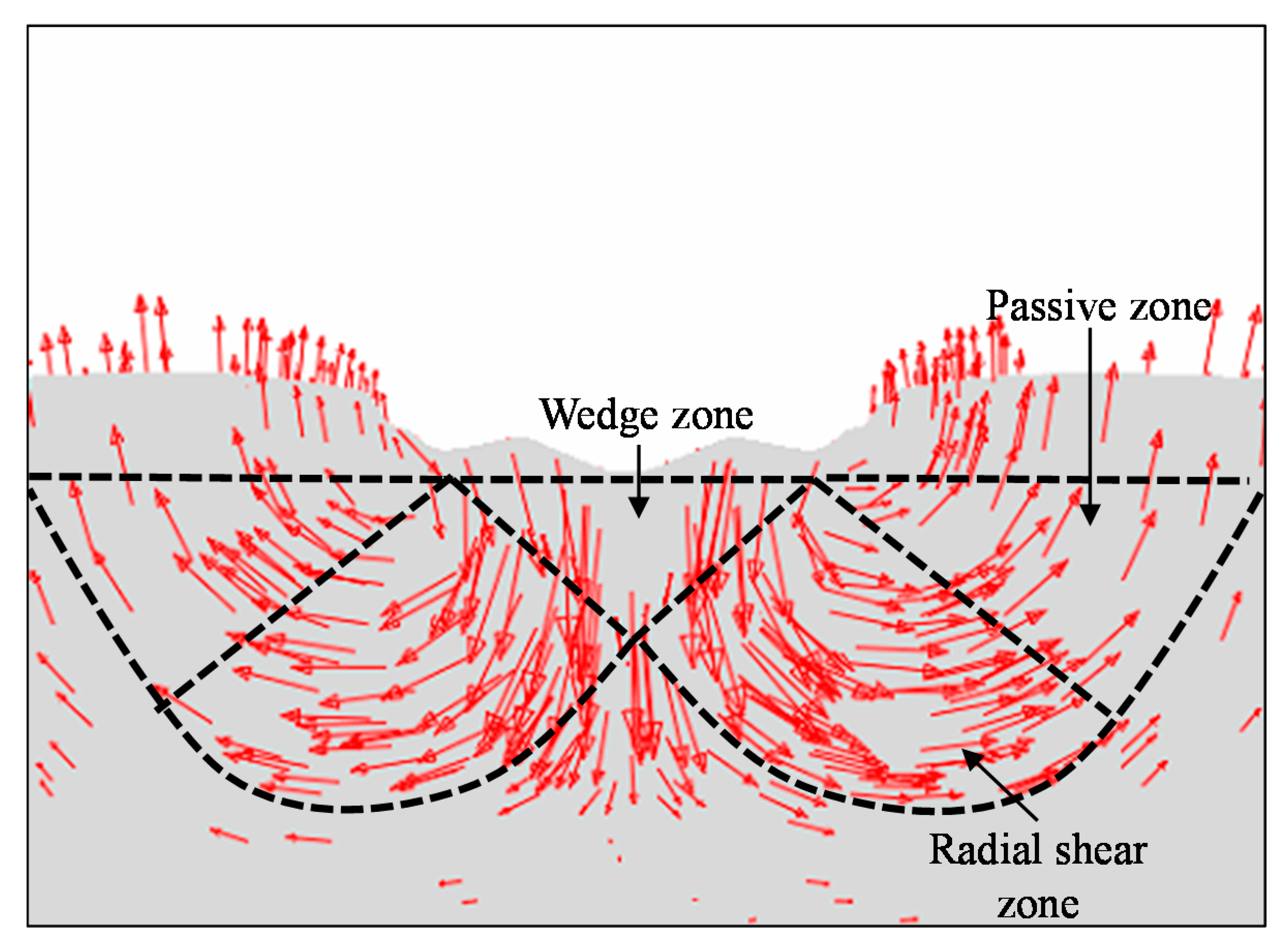
To verify the CEL modelling qualitatively, the instantaneous velocity vector plot in a velocity field is illustrated, as shown in Figure 9. We could investigate the mechanism of the forced replacement method in terms of the sequences, representing the soil flow. As shown in Figure 9, the soil flow as dotted lines comprise wedge zone, radial shear zone, and passive zone. It is very similar to the general bearing capacity theory for a strip foundation proposed by Terzaghi [22]. As the replacement occurs, the magnitude of vertical flow decreases, whereas the magnitude of lateral and heave flow increases. Based on the instantaneous velocity vector plot, the range and magnitude of soil heave can be predicted practically and qualitatively.
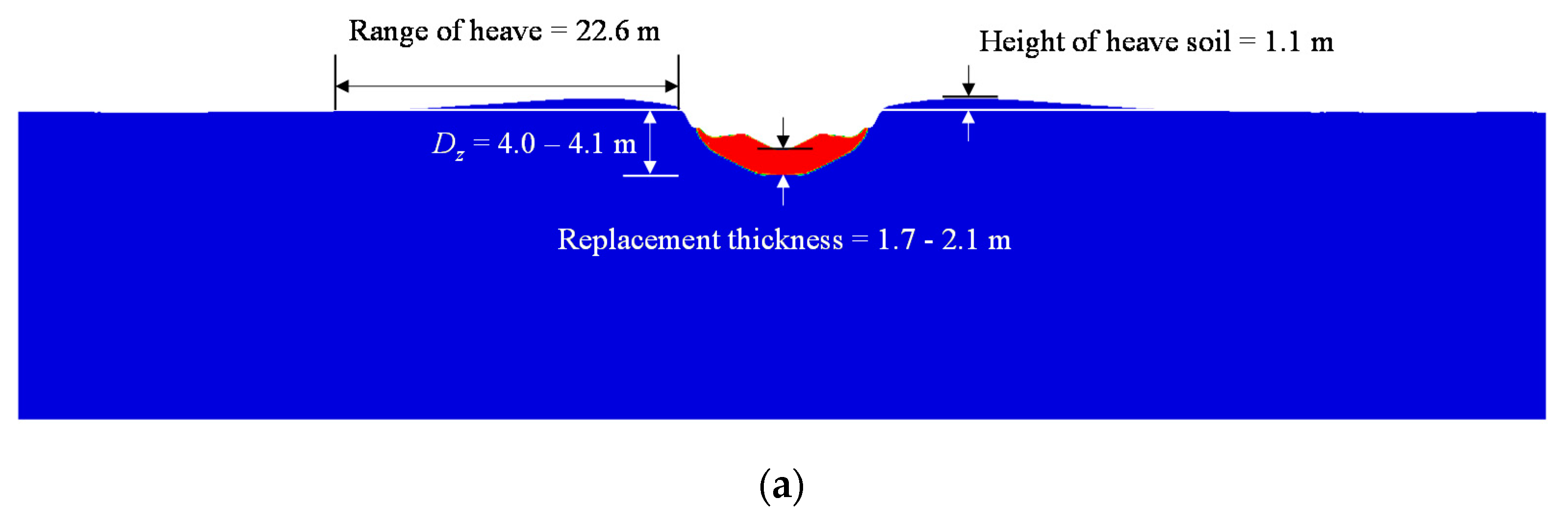
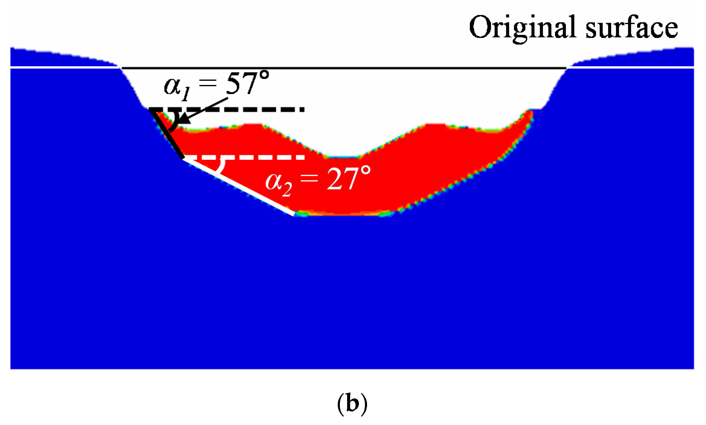
Figure 10 illustrates the results of simulating forced replacement method for H = 2.0 m. For the embankment height of 2.0 m, the replacement depth and replacement thickness are approximately 4.0–4.1 m and 1.7–2.1 m, respectively. When compared with the field investigations, the replacement depth of 4.0–4.1 m from CEL analyses is similar to the measured replacement depth of 4.0–5.0 m. In addition, the height and range of soil heave are about 1.1 m and 22.6 m. In addition, the replacement angle α ranges from 27 to 57 degrees; hence, the replacement shape can be predicted with varying the embankment geometries, such as the height, width, and angle of embankment. Therefore, it can be extremely useful to estimate the reasonable quantity of soil for the replacement, based on the predicted replacement shape. Based on the comparison between results of measured in field test and CEL analyses, it is found that the results of CEL analyses quantitatively agree well with the results of the field tests, also ensuring the reasonable accuracy of CEL technique. Furthermore, this simulation shows the capabilities of CEL to simulate the forced replacement method reasonably. Additionally, the engineers can consider not only the constructability factors such as the replacement depth, height and range of soil heave but also the economic factor such as quantity of soil using CEL technique.
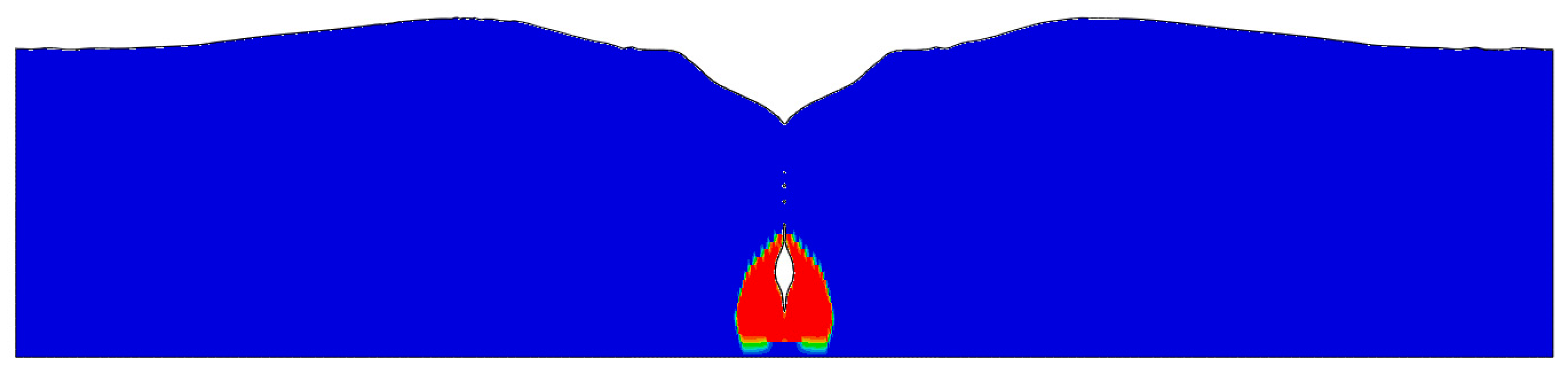
For the embankment height of 2.0 m, the additional embankment should be needed to set ground level straightly, because the maximum settlement of 2.4 m occurred. Thus, the additional analysis for the embankment height of 3.0 m is conducted to review the feasibility of forced replacement method. Figure 11 illustrates the results of simulating forced replacement method for H = 3.0 m. In this case, all of the very soft soil is replaced by embankment, meaning that the embankment soil reaches the bottom of soft soil deposit. Since the soil profile comprised the very deep soft soil deposit of 16.0 m, the quantity of soil for replacement would be substantial and the costs for construction would be increased. Because of this, it is hard to apply the forced replacement method in this site.
4.3. Simulation of Pile Installation on Deep Mixing Soil
For the ground improvement, secondly, the deep mixing method is reviewed to identify the feasibility of that. In this analysis, the self-standing of pile equipment on deep mixing soil and the overturn of pile equipment during pile installation caused by the settlement are comprehensively investigated using CEL technique. It is assumed that the deposit of deep mixing soil is constructed from 0.0 m to 5.0 m. The analysis cases are divided into three cases such as (1) self-standing of pile equipment; (2) effect of pile jacking; and (3) effect of pile driving.
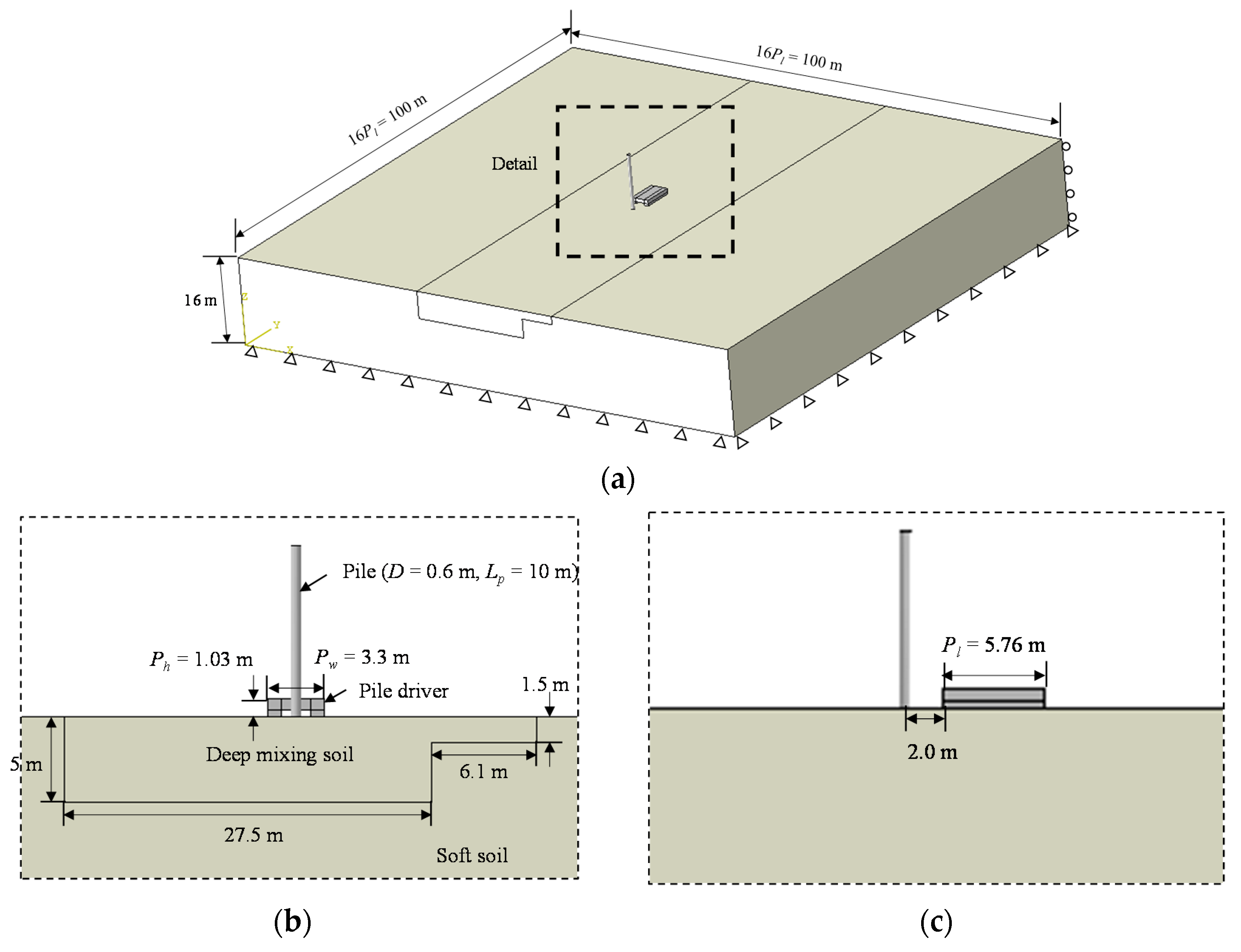
Figure 12 represents a CEL model and boundary conditions for the simulation of pile installation on deep mixing soil. The dimensions of the domains are composed of about 16 times the pile equipment length (Pl) and a height of 16.0 m, to minimize the wave reflecting effect caused by the pile driving. At the sides of the domains, a zero flow velocity normal to those planes is prescribed, and a zero follow velocity in the vertical direction is imposed at the base of the domains [6,13]. The pile domain and soil domain are imposed on the Lagrangian coordinate and Eulerian coordinate, respectively. The input parameters for analyses are summarized in Table 2, based on the geotechnical investigation. Also, the contact pressure of pile equipment is considered as 183.7 kN/m2, according to the design report [28]. For the pile jacking, the velocity of pile jacking is considered as 1 m/sec. For the pile driving, discrete hammer blows are imposed by a time-load curve applied at the reference point of the pile, as shown in Figure 13 [13], and the pile driving energy is considered as 100 kN·m.
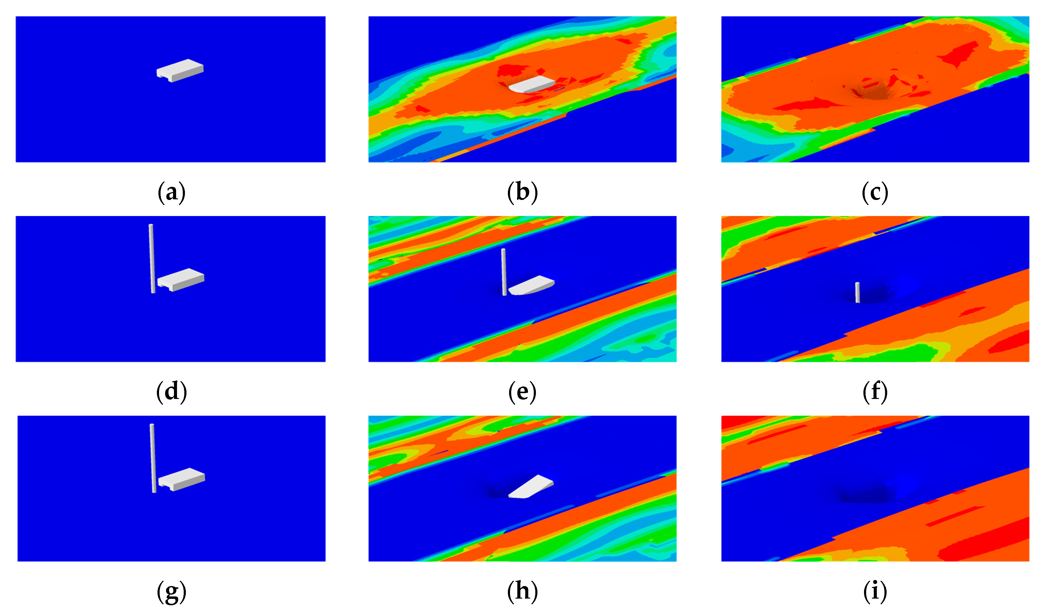
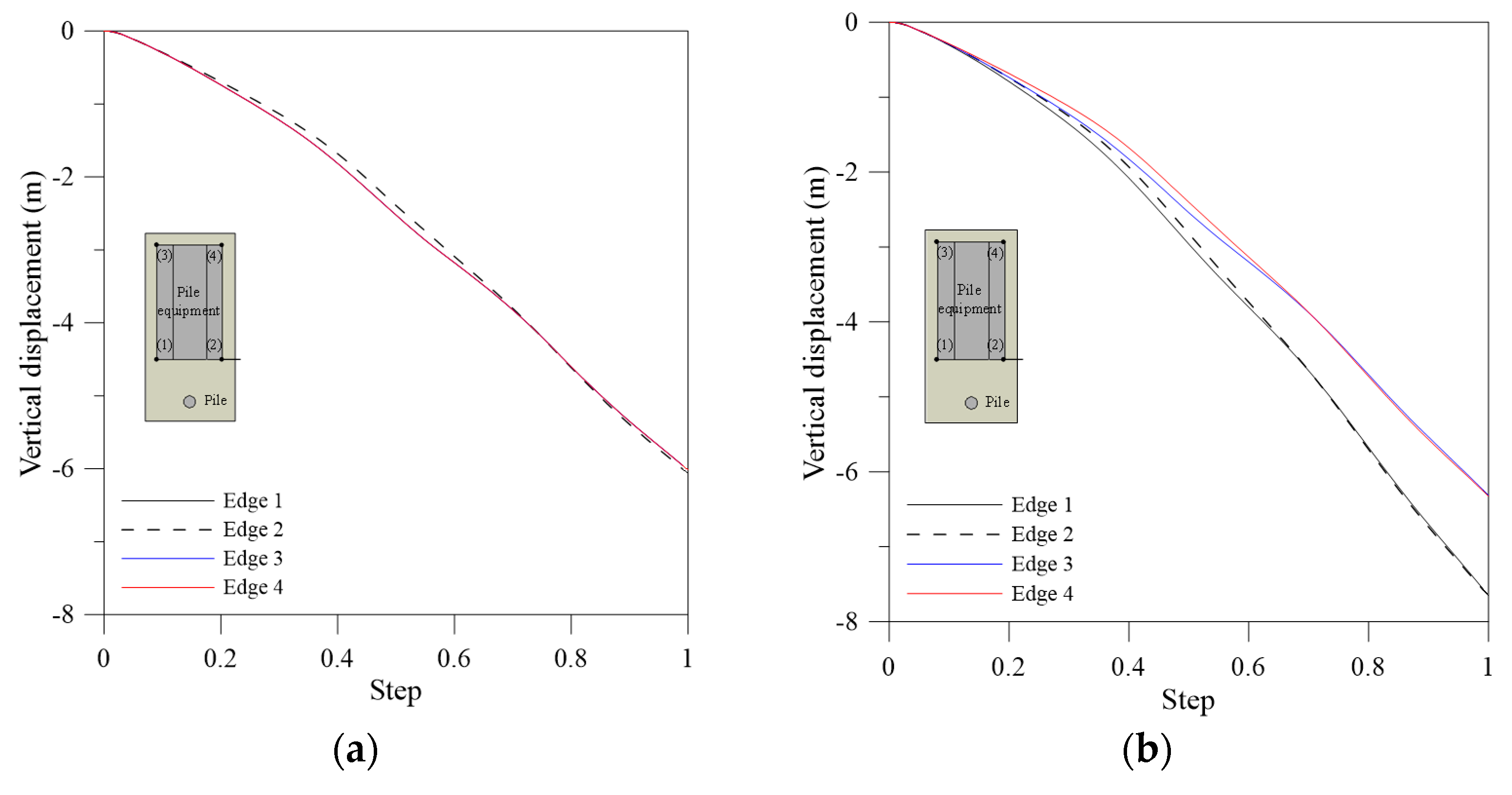
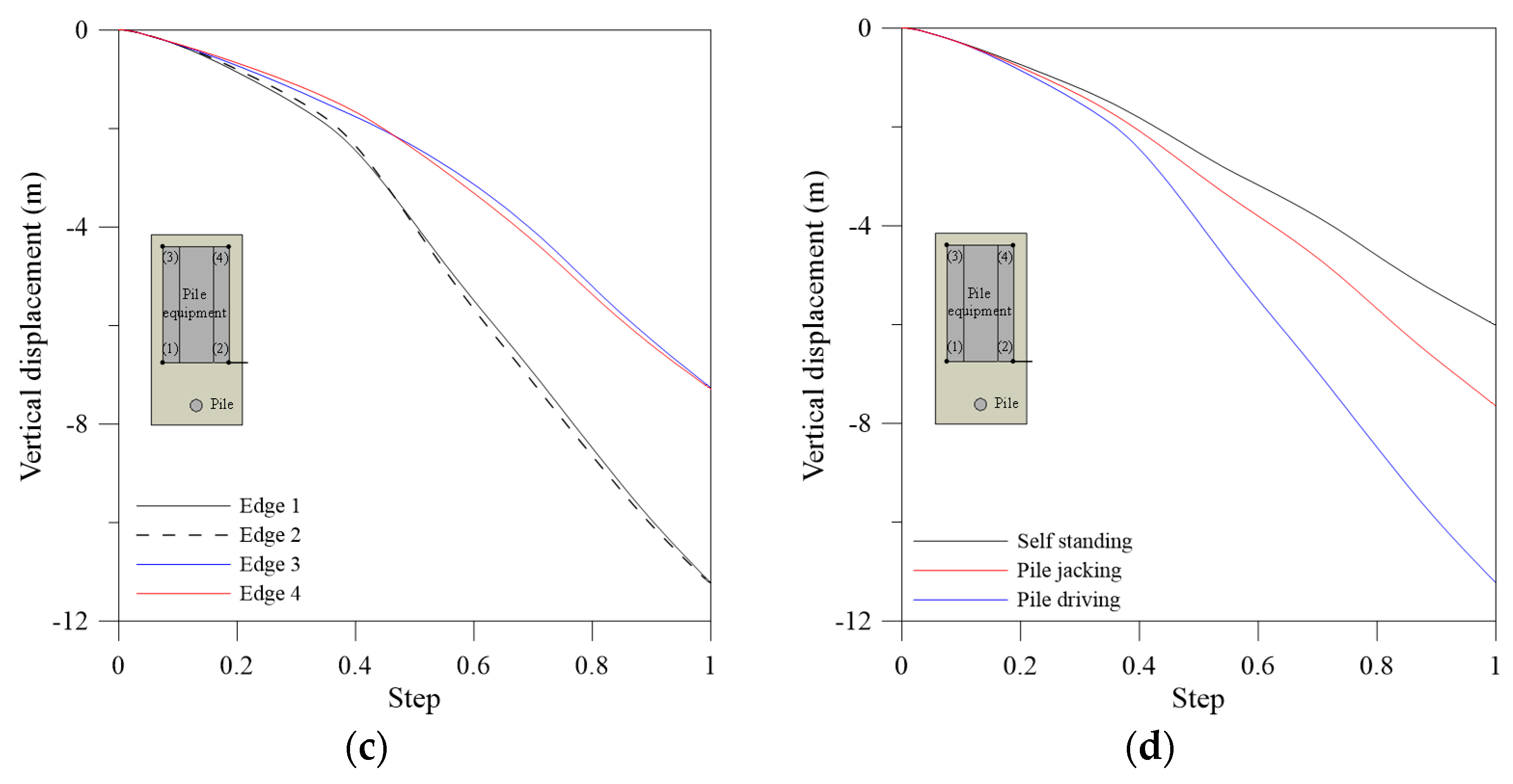
Figure 14 illustrates the results of simulating pile installation on deep mixing soil. As shown in Figure 14, the pile equipment could not be self-standing, also, in the cases of pile jacking and driving, the pile equipment during pile installation settle and overturn, because of being not enough bearing capacity of pile equipment to resist overturning. To investigate the behavior of pile equipment, the vertical displacements at each edge of pile equipment are checked, as shown in Figure 15. For the self-standing of pile equipment, the vertical displacements at all of the edges are similar. However, the differential vertical displacements at each edge occurs during the pile installation, especially, the vertical displacements in the front of the pile equipment are larger than those of the rear. In addition, the vertical displacements during the pile installation are larger than those in case of self-standing of pile equipment. It is indicated that the behavior of pile equipment is influenced by the pile installation loading such as pile jacking and driving.
The deep mixing method has a disadvantage of expensive costs for construction. Also, the soil conditions composed of very deep soft soil in this site is unfavorable to economic feasibility. Thus, the extremely expensive costs for construction would be expected in order to ensure enough bearing capacity for constructability using deep mixing methods. Based on this point, it is hard to consider the deep mixing method in this site.
4.4. Discussion
Figure 16 illustrates the comparison of internal energy (Ei) and kinetic energies (Ek) for forced replacement method and pile installation on deep mixing soil. The energy balance can be used to check the appropriate analysis in CEL technique. The ratio of kinetic energy to internal energy (Ek/Ei) should has the small fraction, typically meaning under 5%. For forced replacement methods, Ek/Ei of H = 1, 2 and 3 m were 2.7%, 0.1% and 0.5%, respectively, at the final analysis step. For pile installation on deep mixing soil, Ek/Ei of self-standing, pile jacking and pile driving were 1.9%, 1.9% and 1.6%, respectively. Based on the results of energy balance, it is found that all cases in the present analysis are in equilibrium and appropriate.
Based on the results of CEL analyses, two ground improvement methods, i.e., the forced replacement method and the deep mixing method, can improve a certain soil strength, however, there are the risks for constructability during constructions such as pile installation. In addition, the soil conditions composed of very deep soft soil in this site is unfavorable to economic feasibility. Therefore, the installation of temporary bridges is more economically analyzed than the two ground improvement methods, and the temporary bridges were actually installed during the real construction.
5. Conclusions
The main objective of this study is to investigate the behavior of very soft soil and constructability of two ground improvement methods, i.e., forced replacement method and deep mixing method. For this purpose, the large deformation finite element (LDFE) analyses using Coupled Eulerian-Lagrangian technique are implemented. The results of the CEL modelling are verified by comparison between those and the field investigations with settlement, height, and range of soil heave. Additionally, to examine the constructability and economics of each method, comprehensive reviews are performed. The following conclusions could be drawn from the present study:
- The CEL technique is successfully applied to solve the constructability problems of sites on very soft soil. The applicability of the CEL modelling is verified by comparison between those and the field investigations with settlement, height, and range of soil heave for the forced replacement method. Furthermore, the replacement shape can be predict with varying the embankment geometries such as the height, width, and angle of embankment, therefore, it can be extremely useful to estimate the reasonable quantity of soil for the replacement.
- For the deep mixing method, the pile equipment could not be self-standing, also, in cases of pile jacking and driving, the pile equipment during pile installation settle and overturn, because of being not enough bearing capacity of pile equipment to resist overturning. In addition, the vertical displacements settlement at each edge occurs during the pile installation, especially, the vertical displacements in the front of the pile equipment are larger than those of the rear. The vertical displacements during the pile installation are larger than those in the case of self-standing of pile equipment. It is indicated that the behavior of pile equipment is influenced by the pile installation loading, such as pile jacking and driving.
- Two ground improvement methods can improve a certain soil strength, however, there are the risks for constructability during constructions, such as pile installation, also the soil conditions composed of very deep soft soil in this site is unfavorable to economic feasibility.
- The behavior of very soft soil and constructability with methods can be investigated using CEL technique, which would be useful tools for comprehensive reviews in preliminary design.
Acknowledgments
This research was supported by Basic Science Research Program through the National Research Foundation of Korea (NRF) funded by the Ministry of Education (Grant No. 2016R1A6A3A03010454) for Junyoung Ko. Sangseom Jeong and Junghwan Kim would like to thank the National Research Foundation of Korea (NRF) (Grant No. 2011-0030040) for supporting this research work.
Author Contributions
Junyoung Ko performed the numerical studies and wrote the draft of the paper; Sangseom Jeong designed this research and assisted with the writing of the paper; Junghwan Kim analyzed the numerical data and assisted with the numerical analyses.
Conflicts of Interest
The authors declare no conflict of interest.
References
- Whitlow, R. The Geology of the Gold Coast Region. Geoscientific Consultancy Report; Gold Coast City Council: Gold Coast, Australia, 2000.
- Zainorabidin, A.; Wijeyesekera, D. Geotechnical Challenges with Malaysian Peat. In Proceedings of the Advances in Computing and Technology, London, UK, 23 January 2007; pp. 252–261. [Google Scholar]
- American Society for Testing and Materials (ASTM). Standard Practice for Classification of Soils for Engineering Purpose (Unified Soil Classification System); D2487; American Society for Testing and Materials: West Conshohocken, PA, USA, 2011. [Google Scholar]
- Huang, P.-T.; Patel, M.; Santagata, M.C.; Bobet, A. FHWA/IN/JTRP-2008/2, Classification of Organic Soils; Federal Highway Administration: Indianapolis, IN, USA, 2009.
- Tho, K.K.; Leung, C.F.; Chow, Y.K.; Palmer, A.C. Deep cavity flow mechanism of pipe penetration in clay. Can. Geotech. J. 2012, 49, 59–69. [Google Scholar] [CrossRef]
- Qiu, G.; Henke, S. Controlled installation of spudcan foundations on loose sand overlying weak clay. Mar. Struct. 2011, 24, 528–550. [Google Scholar] [CrossRef]
- Yi, J.T.; Lee, F.H.; Goh, S.H.; Zhang, X.Y.; Wu, J.-F. Eulerian finite element analysis of excess pore pressure generated by spudcan installation into soft clay. Comput. Geotech. 2012, 42, 157–170. [Google Scholar] [CrossRef]
- Kim, Y.H.; Hossain, M.S. Dynamic installation of OMNI-Max anchors in clay: Numerical analysis. Geotechnique 2015, 65, 1029–1037. [Google Scholar] [CrossRef]
- Kim, Y.H.; Hossain, M.S.; Wang, D. Effect of strain rate and strain softening on embedment depth of a torpedo anchor in clay. Ocean Eng. 2015, 108, 704–715. [Google Scholar] [CrossRef]
- Jeong, S.S.; Lee, K.W.; Ko, J.Y. A Study on the 3D Analysis of Debris Flow Based on Large Deformation Technique (Coupled Eulerian-Lagrangian). J. Korean Geotech. Soc. 2015, 31, 45–57. [Google Scholar] [CrossRef]
- Kim, Y.M. Analytical Methods for Rainfall-Induced Landslide Considering Hydraulic-Mechanical Coupling and Strain Softening. Ph.D. Thesis, Yonsei University, Seoul, Korea, 2015. [Google Scholar]
- Ko, J. Evaluation of Bearing Capacity for Open-Ended Piles with Soil Plugging. Ph.D. Thesis, Yonsei University, Seoul, Korea, 2015. [Google Scholar]
- Ko, J.; Jeong, S.; Lee, J.K. Large deformation FE analysis of driven steel pipe piles with soil plugging. Comput. Geotech. 2016, 71, 82–97. [Google Scholar] [CrossRef]
- Pucker, T.; Grabe, J. Numerical simulation of the installation process of full displacement piles. Comput. Geotech. 2012, 45, 93–106. [Google Scholar] [CrossRef]
- Qin, H.; Cai, Z.; Hu, H.; Wang, J.; Ye, W.; Chen, Y. Numerical Analysis of Gravity Coring Using Coupled Eulerian-Lagrangian Method and a New Corer. Mar. Georesour. Geotechnol. 2016, 34, 403–408. [Google Scholar] [CrossRef]
- Tho, K.K.; Leung, C.F.; Chow, Y.K.; Swaddiwudhipong, S. Eulerian finite element simulation of spudcan-pile interaction. Can. Geotech. J. 2013, 50, 595–608. [Google Scholar] [CrossRef]
- Lee, S. A Study on the Excavation Damage Zone (EDZ) under TBM Excavation. Master Thesis, Yonsei University, Seoul, Korea, 2016. [Google Scholar]
- Kim, B.J. Case Studies on Geotechnical Construction; Wongisul: Seoul, Korea, 2006. [Google Scholar]
- Ryu, N.H.; Ryu, Y.T. A Study on the Characteristics of Organic Soil in Young-dong Region. J. Korean Soc. Agric. Eng. 1985, 27, 77–85. [Google Scholar]
- Koo, J.M.; Park, J.S.; Park, J.S.; Park, H.G. Consolidation Characteristics of Organic Soil in Young-Dong Region. In Proceedings of the Korean Society of Civil Engineers Conference, Yong-Pyung, Korea, 27–28 October 2000; pp. 395–398. [Google Scholar]
- Jang, D.H. An Experimental Study on the Engineering Characteristics of Organic Soil in Dong-Hae. Master’s Thesis, Catholic Kwandong University, Gangneung, Korea, 2011. [Google Scholar]
- Terzaghi, K. Theoretical Soil Mechanics; Wiley: New York, NY, USA, 1943. [Google Scholar]
- Yasuhara, K.; Tsukamoto, Y. A Rapid Banking Method Using the Resinous Mesh on a Soft Reclaimed Land. In Proceedings of the 2nd International Conference on Geotextiles, Las Vegas, NV, USA, 1–6 August 1982; pp. 635–640. [Google Scholar]
- Lee, S.H. A Study on Deformation of Soft Clay Foundation by Soil Structure. Ph.D. Thesis, Hanyang University, Seoul, Korea, 1992. [Google Scholar]
- Abaqus Analysis User’s Manual; Dassault Systemes: Providence, RI, USA, 2013.
- Cho, J.Y.; Lee, J.H.; Jeong, S.S.; Lee, J.H. The settlement behavior of piled raft in clay soils. Ocean Eng. 2012, 53, 153–163. [Google Scholar] [CrossRef]
- Jeong, S.S.; Lee, J.H.; Lee, C.J. Slip effect at the pile-soil interface on dragload. Comput. Geotech. 2004, 31, 115–126. [Google Scholar] [CrossRef]
- Korea Institute of Geotechnology. Design Report for Wonju-Gangnueng Railway Project in Zone 11–2; Korea Institute of Geotechnology: Seoul, Korea, 2015. [Google Scholar]
Figure 1.
Location of the study area in South Korea.

Figure 2.
Soil profile with test results: (a) Soil profile; (b) result of N value; and (c) result of cone resistance.
Figure 2.
Soil profile with test results: (a) Soil profile; (b) result of N value; and (c) result of cone resistance.

Figure 3.
Properties of organic soil: (a) Water content; (b) soil cohesion; (c) organic content.

Figure 4.
Schematic diagram of the forced replacement method.

Figure 5.
Field investigations: (a) Settlement; (b) range and height of heave soil.

Figure 6.
Deformation of a continuum in analysis: (a) Lagrangian analysis; (b) Eulerian analysis.

Figure 7.
Relationship between replacement depth and computation time.

Figure 8.
CEL model for the simulation of forced replacement method: (a) Dimensions and boundary conditions; (b) typical mesh.
Figure 8.
CEL model for the simulation of forced replacement method: (a) Dimensions and boundary conditions; (b) typical mesh.

Figure 9.
Instantaneous velocity plots.

Figure 10.
Results of simulating forced replacement method (H = 2.0 m): (a) Replacement depth, range and height of heave soil; (b) replacement angle.
Figure 10.
Results of simulating forced replacement method (H = 2.0 m): (a) Replacement depth, range and height of heave soil; (b) replacement angle.


Figure 11.
Results of simulating forced replacement method (H = 3.0 m).

Figure 12.
CEL model and boundary conditions for the simulation of pile installation on deep mixing soil: (a) 3D view; (b) front view; and, (c) side view.
Figure 12.
CEL model and boundary conditions for the simulation of pile installation on deep mixing soil: (a) 3D view; (b) front view; and, (c) side view.

Figure 13.
Pile driving load with time for one hammer blow (modified from Ko et al. [13]).
Figure 13.
Pile driving load with time for one hammer blow (modified from Ko et al. [13]).

Figure 14.
Results of simulating pile installation on deep mixing soil: (a) Self-standing of pile equipment at initial stage; (b) self-standing of pile equipment at medium stage; (c) self-standing of pile equipment at final stage; (d) pile jacking at initial stage; (e) pile jacking at medium stage; (f) pile jacking at final stage; (g) pile driving at initial stage; (h) pile driving at medium stage; and, (i) pile driving at final stage.

Figure 15.
Vertical displacement with edges of pile equipment: (a) Self-standing of pile equipment; (b) pile jacking; (c) pile driving; and (d) comparison with methods of pile installation.
Figure 15.
Vertical displacement with edges of pile equipment: (a) Self-standing of pile equipment; (b) pile jacking; (c) pile driving; and (d) comparison with methods of pile installation.


Figure 16.
Comparison of internal and kinetic energies: (a) Forced replacement method; (b) pile installation on deep mixing soil.
Figure 16.
Comparison of internal and kinetic energies: (a) Forced replacement method; (b) pile installation on deep mixing soil.


Table 1.
Characteristics of organic soil in Yeongdong area (Jang [21]).
Table 1.
Characteristics of organic soil in Yeongdong area (Jang [21]).
| Water Content (%) | Liquid Limit (%) | Plastic Index | Organic Content (%) | pH | |
|---|---|---|---|---|---|
| Sokcho | 103.2–178.5 | 100.4–170.3 | 49.8–85.7 | 10.9–18.5 | 4.3–6.5 |
| Yangyang | 100.4–179.0 | 104.7–180.4 | 52.2–97.7 | 10.5–18.7 | 4.3–6.8 |
| Gangneung | 101.3–341.7 | 75.5–200.8 | 9.2–73.6 | 2.27–2.33 | 5.1–6.4 |
Table 2.
Input parameter for Coupled Eulerian–Lagrangian (CEL) analyses (Korea Institute of Getechnology [28]).
Table 2.
Input parameter for Coupled Eulerian–Lagrangian (CEL) analyses (Korea Institute of Getechnology [28]).
| Model | Soil Cohesion (kPa) | Internal Friction Angle (deg.) | Effective Unit Weight (kN/m3) | Elastic Modulus (MPa) | Poisson’s Ratio | |
|---|---|---|---|---|---|---|
| Organic soil (very soft soil) | * M.C. | 2.4 | 0 | 1 | 0.24 | 0.49 |
| Embankment | M.C. | 15.0 | 25 | 9 | 20 | 0.33 |
| Deep mixing soil | M.C. | 21.6 | 0 | 3 | 4.3 | 0.49 |
* M.C. = Mohr-Coulomb model.
Table 3.
Convergence study for mesh.
| Name | sm/B0 | Replacement Depth Dz (m) | Computation Time (s) | Number of Elements |
|---|---|---|---|---|
| Mesh 1 | 0.0833 | 5.0 | 6.5 | 3243 |
| Mesh 2 | 0.0417 | 4.5 | 44.6 | 32,586 |
| Mesh 3 | 0.0167 | 4.2 | 204.3 | 69,786 |
| Mesh 4 | 0.0083 | 4.1 | 930.5 | 163,416 |
| Mesh 5 | 0.0042 | 4.1 | 7260.1 | 471,516 |
© 2017 by the authors. Licensee MDPI, Basel, Switzerland. This article is an open access article distributed under the terms and conditions of the Creative Commons Attribution (CC BY) license (http://creativecommons.org/licenses/by/4.0/).
Share and Cite
MDPI and ACS Style
Ko, J.; Jeong, S.; Kim, J. Application of a Coupled Eulerian-Lagrangian Technique on Constructability Problems of Site on Very Soft Soil. Appl. Sci. 2017, 7, 1080. https://0-doi-org.brum.beds.ac.uk/10.3390/app7101080
AMA Style
Ko J, Jeong S, Kim J. Application of a Coupled Eulerian-Lagrangian Technique on Constructability Problems of Site on Very Soft Soil. Applied Sciences. 2017; 7(10):1080. https://0-doi-org.brum.beds.ac.uk/10.3390/app7101080
Chicago/Turabian StyleKo, Junyoung, Sangseom Jeong, and Junghwan Kim. 2017. "Application of a Coupled Eulerian-Lagrangian Technique on Constructability Problems of Site on Very Soft Soil" Applied Sciences 7, no. 10: 1080. https://0-doi-org.brum.beds.ac.uk/10.3390/app7101080
Note that from the first issue of 2016, this journal uses article numbers instead of page numbers. See further details here.