Hybrid Prediction Model of the Temperature Field of a Motorized Spindle

1
Test and Analysis Center, Shenyang Jianzhu University, No. 9, Hunnan East Road, Hunnan New District, Shenyang 110168, China
2
School of Mechanical Engineering, Shenyang Jianzhu University, No. 9, Hunnan East Road, Hunnan New District, Shenyang 110168, China
*
Author to whom correspondence should be addressed.
Appl. Sci. 2017, 7(10), 1091; https://0-doi-org.brum.beds.ac.uk/10.3390/app7101091
Submission received: 26 September 2017
/
Revised: 17 October 2017
/
Accepted: 18 October 2017
/
Published: 22 October 2017
(This article belongs to the Special Issue Soft Computing Techniques in Structural Engineering and Materials)
Abstract
:The thermal characteristics of a motorized spindle are the main determinants of its performance, and influence the machining accuracy of computer numerical control machine tools. It is important to accurately predict the thermal field of a motorized spindle during its operation to improve its thermal characteristics. This paper proposes a model to predict the temperature field of a high-speed and high-precision motorized spindle under different working conditions using a finite element model and test data. The finite element model considers the influence of the parameters of the cooling system and the lubrication system, and that of environmental conditions on the coefficient of heat transfer based on test data for the surface temperature of the motorized spindle. A genetic algorithm is used to optimize the coefficient of heat transfer of the spindle, and its temperature field is predicted using a three-dimensional model that employs this optimal coefficient. A prediction model of the 170MD30 temperature field of the motorized spindle is created and simulation data for the temperature field are compared with the test data. The results show that when the speed of the spindle is 10,000 rpm, the relative mean prediction error is 1.5%, and when its speed is 15,000 rpm, the prediction error is 3.6%. Therefore, the proposed prediction model can predict the temperature field of the motorized spindle with high accuracy.
1. Introduction
The motorized spindle unit is crucial to numerical control (NC) machine tools and the key component to guarantee the precision of machines. Its performance directly influences the technology used and determines the development of the machine tool [1]. The motorized spindle unit is indispensable to high performance computer numerical control (CNC) machine tools. Several studies have focused on improving the spindle [2,3,4,5]. The motorized spindle incurs mechanical and electromagnetic losses because of its high speed and non-sinusoidal power supply. Most of these losses are transformed into heat and transferred to the surrounding air, cooling fluid, and machine parts. This results in uneven heat deformation of the parts of the machine, which directly affects the accuracy of the spindle and the bearing preload. As many as 75% of the overall geometrical errors in workpieces manufactured by machines are considered to be induced by the effects of temperature [6]. The temperature of the motorized spindle is an important index to evaluate its performance at high speeds [7]. High-power and high-speed motorized spindles feature a larger rise in temperature than surroundings, which is therefore important to control.
There are two methods for controlling the rise in temperature of the motorized spindle. One involves actively controlling the cooling and lubrication systems to avoid high temperatures, and the other consists of optimizing the design of the structure of the motorized spindle [8,9]. These two methods are different, but both require the development of a thermal model for the motorized spindle to predict the temperature field. The Ellesmere Company has been developing CAD software for motor design software for the last 10 years, which includes modules for thermal error calculation [10]. However, it is challenging to effectively calculate thermal error in the motorized spindle as it is fundamentally different from an ordinary motor. The motorized spindle system contains a few subsystems, such as water cooling, lubrication, and the inverter. Thus, its heat generation and transfer processes are more complex.
Finite element analysis is often used in a simplified thermal design of the motorized spindle unit [11,12]. Such thermal boundary conditions as the processing conditions of the heating and cooling environments are loaded into the model to simulate the temperature distribution of the motorized spindle. Jedrzejewski et al. [13,14,15,16,17] researched finite element thermal modeling of NC machine tools and created a hybrid model of a high-speed machining center spindle box using finite element modeling. This method was used to model the components of the symmetrical axis. A comparison of the results between the hybrid prediction model and the finite difference method shows that the prediction error in the hybrid model was less than 2 °C. Neugebauer et al. [18] proposed a method that allows the permanent adaptation of the heat transmission coefficient to better apply convective heat transmission to time-variable thermal simulations, especially for mechanical finite element models. Holkup [19] presented a thermo-mechanical model of spindles that predicts temperature distribution and thermal growth by considering transient changes in the bearing stiffness and contact loads.
Zhang et al. [20] built a model for the thermal characteristics of the high-speed motorized spindle using finite element analysis and calculated the static/transient temperature field as well as the thermal coupled field. Chen et al. [21] proposed a bearing thermo-mechanical dynamic model that considers preload methods and thermal responses, and analyzed frictional losses and the support stiffness of the bearings. The electromagnetic loss of the built-in motor with input power was investigated using electromagnetism. Based on the analyses of the boundary conditions of heat generation and heat convection, a solution procedure was designed to analyze the comprehensive thermo-mechanical dynamic behaviors of the motorized spindle. In the same year, Chen et al. [22] created a motor loss model based on electromagnetics for finite element thermal analysis.
Even when considering the virtues of thermal models of the motorized spindle, where multi-field coupling and the dynamic characteristics of its thermal state can be easily considered, its nonlinear characteristics are very difficult to handle. Moreover, cooling methods for the motor and the bearings are usually implemented using a convective cooling fluid. The coefficient of heat convection that represents the relationship between the solid surface and the cooling medium is influenced by several factors. It is challenging to predict this coefficient, and this yields models with inadequate accuracy. An effective method to improve the predictive accuracy of the thermal field involves creating a model for the heat transfer coefficient using a heuristic approach.
In practice, the internal temperature of the motorized spindle is important. Predictions of the temperature field of the motorized spindle based on the mechanistic model are reliable, but the accuracy of prediction can be further improved if the model takes advantage of the easily measured surface temperature of the spindle. In this paper, a hybrid model that combines the finite element model with temperature data is proposed and the dynamic temperature field of the motorized spindle is predicted. In the proposed model, a heuristic approach based on genetic algorithm is used to optimize the heat transfer coefficient. The model was verified by comparing the results of simulations with those of experiments, and yielded high prediction accuracy.
2. Heat Generation and Heat Transfer in a Motorized Spindle
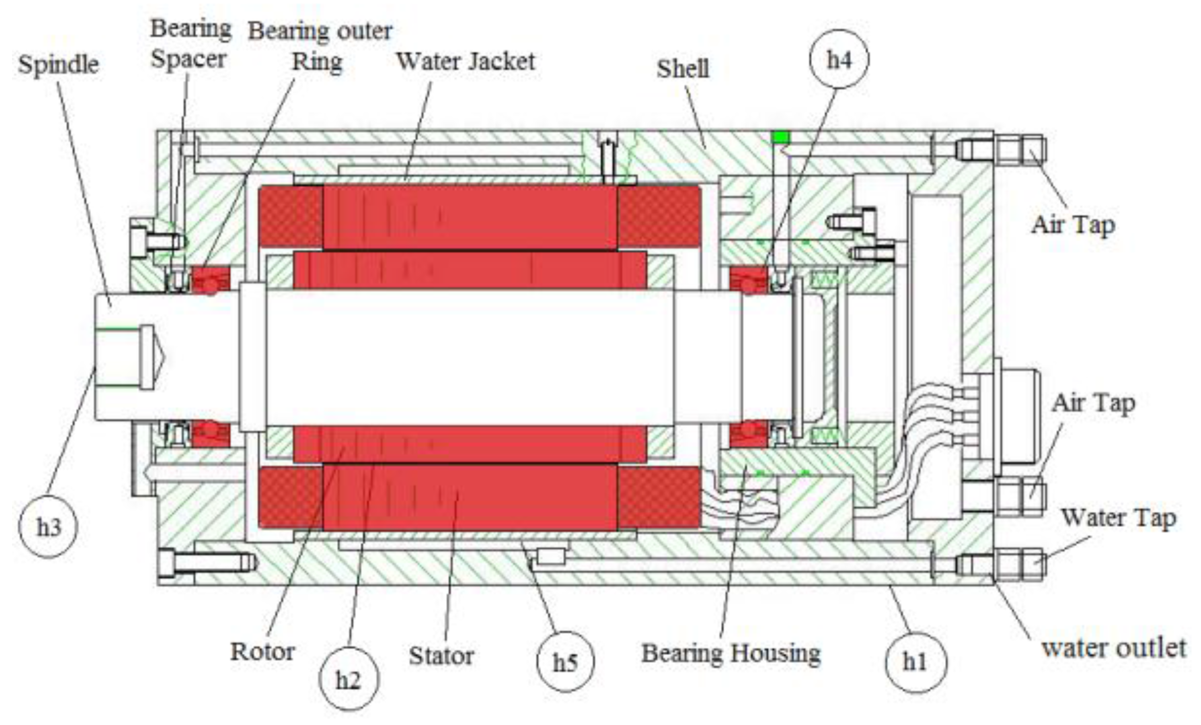
The motorized spindle is a mechatronic product composed of a stator, a rotor, a spindle, a shell, a water jacket, front bearings, rear bearings, and bearing housing. It is built into an asynchronous alternating current motor, and its structure is as shown in Figure 1. The rotor and spindle are integrated through pressure matching, and the latter is supported by front and rear bearings. The stator of the motor is fixed on a shell through a water jacket. It is well known that heat generation is inevitable owing to high speed of the motorized spindle. The main sources of heat generation are the heating of the motor, and frictional heat from the front and rear bearings. Furthermore, the power supply of the motorized spindle is an inverter that generates higher harmonics, because of which the motor generates additional resistive losses owing to the copper in the stator and rotor, the iron in the stator, and additional stray loss. Moreover, the skin effect in the rotor induces greater losses in the copper at power supplies of high frequency. The losses from these high harmonic voltages and currents result in an increase in motor temperature. This causes thermal deformation in the components of the motorized spindle and affects its dynamic performance. Lubrication and cooling systems are designed to prevent the motorized spindle from overheating. In general, the stator of the motorized spindle is cooled using cooling water pumped through a jacket. Bearings are lubricated with oil and gas, where fine drops of oil are carried by compressed gas into the air gap between the stator and rotor, and the clearance of the bearing. These drops then flow out of the motorized spindle. Therefore, the bearings are lubricated, and the rotor, shaft, and bearings are actively cooled.
The above discussion shows that heat transfer in the motorized spindle is complex. The heat transfer mode of the motorized spindle consists mainly of conduction and convection. The equation of energy conservation is as follows:
where , is heat generation, V is the volume of the heat source, is the density of the solid, is that of the fluid, and are the heat capacities of the solid and the fluid, respectively, T is the temperature of the motorized spindle, is fluid velocity, is the Laplace operator, is thermal conductivity, and is the rate of heat generation.
According to heat transfer theory, the relationship between the coefficient of convective heat transfer and temperature is
where is heat flux, is the vector of the coefficient of heat transfer, and is the temperature of the fluid medium.
Five processes contribute to heat transfer in the motorized spindle. Between the surface of the spindle shell and air is natural convection heat transfer, with the heat transfer coefficient given by [23]
Between the gas-gap and the compressed air is the forced convection heat transfer, with the heat transfer coefficient represented as:
where , , , is the speed of airflow in the air gap (m/s), and are the input speed of the compressed air and the speed of rotation of the spindle, respectively, is the radius of the outer surface of the rotor (m), is the dimensionality of the geometry of the air gap (m), is the Reynolds number, is the Nusselt number, is the gap between the stator and the rotor (m), and is the thermal conductivity of air (W/(m·°C)).
Between the spindle end and the environmental air is the forced convective heat transfer, with the heat transfer coefficient given as:
where is the circumferential velocity of the end of the rotor (m/s).
Between the front bearing and the compressed air, and between the rear bearing and the compressed air, is the forced convection of heat. Thus, the coefficients of heat transfer are:
where , , is the average diameter of the bearing (m), is the average distance between the cage and the inner and outer rings of the bearing (m), is the area of axial air flow through the bearing (m2), is the average speed of air flowing through the bearing (m/s), is air flow through the bearing (m3/s), is the angular velocity (rad/s) of the motorized spindle, and the values of , , and are 9.7, 5.33, and 0.8, respectively.
The heat transfer coefficient for the forced convection of the cooling water and the water jacket is:
where , , , is the characteristic velocity (m/s) of the cooling water, is the kinematic viscosity (m2/s) of the cooling water, is the geometric characteristic size (m), is the area of cross-sectional flow (m2), is the circumference of the section of wet flow (m), is the Prandtl number of water, with , and is its thermal conductivity (W/(m·°C)).
The parameters of the cooling and lubrication systems as well as the motion of the motorized spindle are directly related to the heat transfer coefficients, which are dynamic and nonlinear. In traditional finite element modeling of the motorized spindle, these characteristics are ignored, which leads to inaccurate calculations of the temperature field.
The above problem can be solved by optimizing heat transfer coefficients based on test data for temperature. The implementation of this exploits the relationship between temperature and the heat transfer coefficients of the motorized spindle.
3. Hybrid Prediction Model of the Temperature Field of the Motorized Spindle
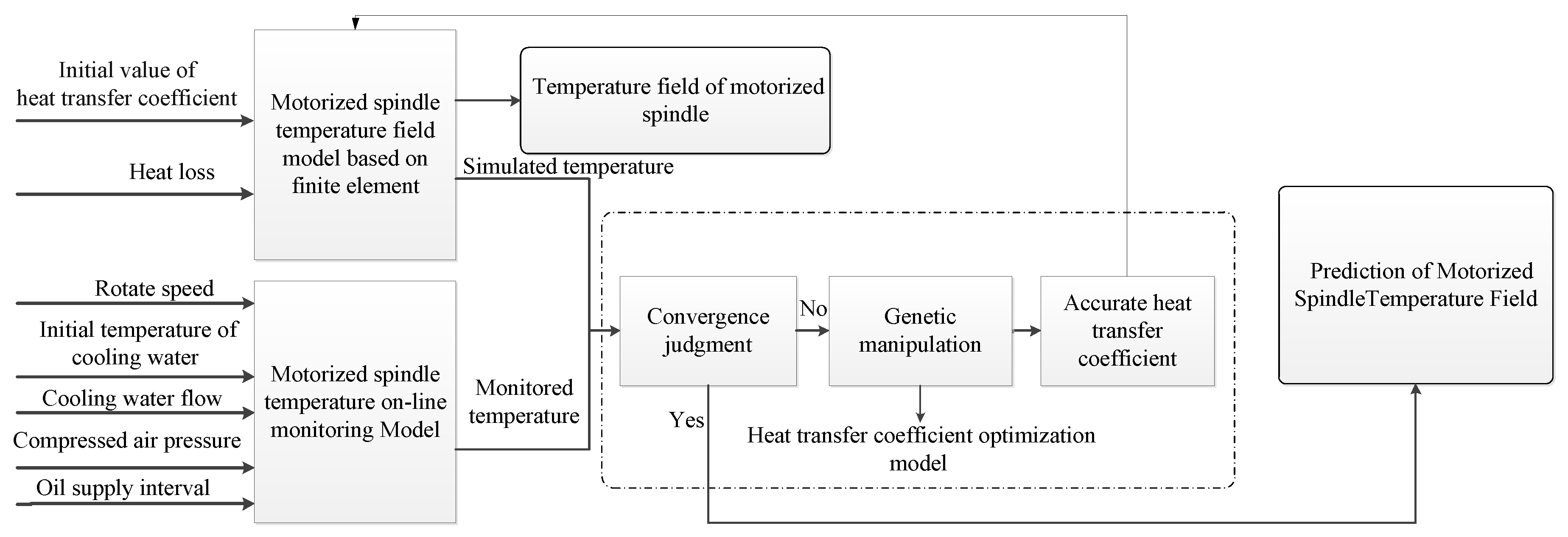
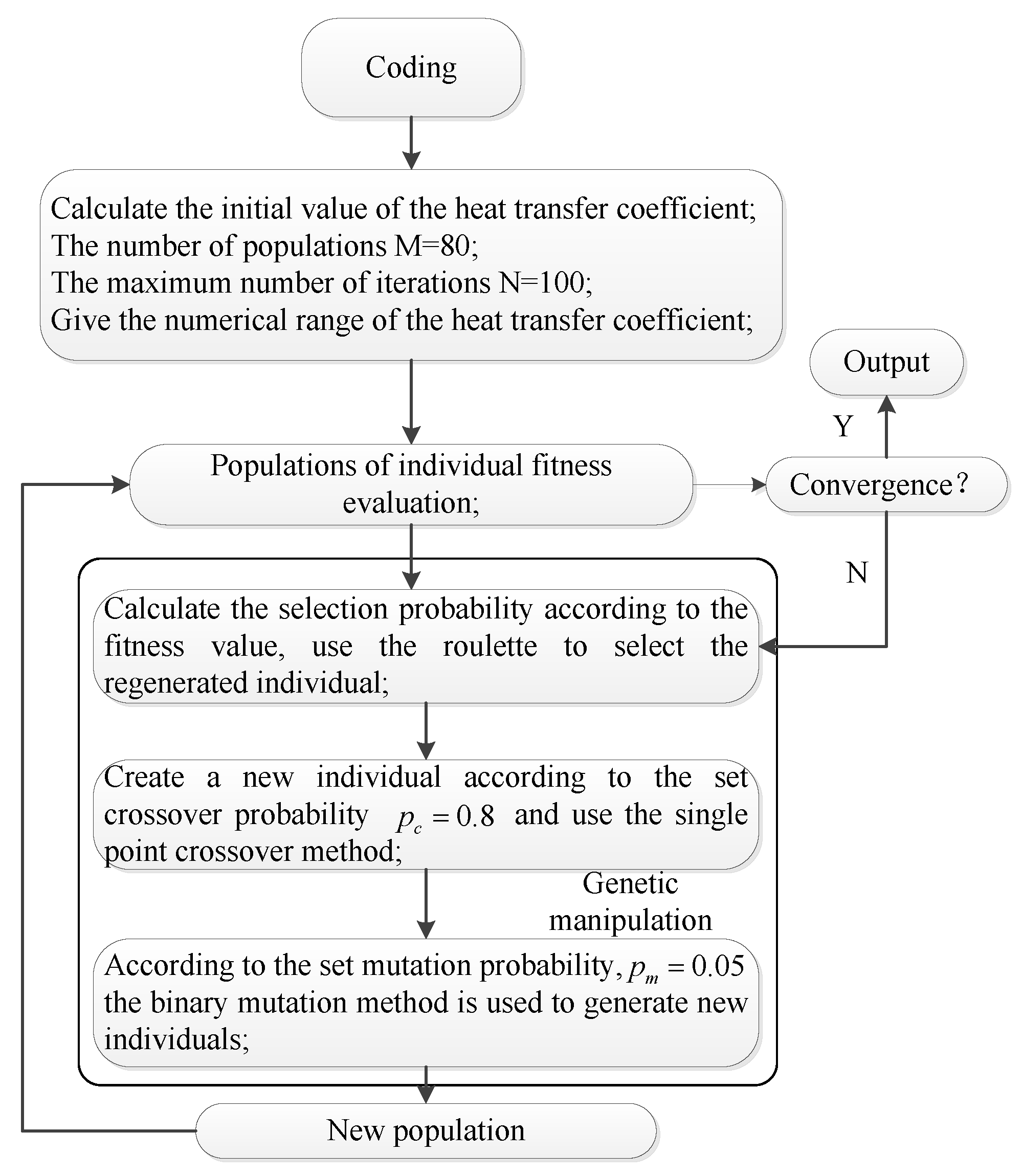
In the traditional temperature field of the motorized spindle model, the heat transfer coefficients at key positions are calculated using an empirical formula that leads to an associated error in the calculation of the temperature field. This paper provides a precise temperature field for the finite element model of the motorized spindle where the heat transfer coefficients are optimized using a genetic algorithm. The finite element model of the boundary conditions of the motorized spindle is then used to accurately obtain the temperature field. The prediction model of the temperature field of the motorized spindle is shown in Figure 2. First, the initial values of the heat transfer coefficients h (h1, h2, h3, h4, and h5) are first calculated according to the empirical formulae shown in Formulae (3)–(7). Heat generation rates are calculated according to losses in the motorized spindle. The boundary conditions of the rates of heat generation and the initial value of the heat transfer coefficients are used as initial conditions of the finite element model to calculate the temperature field. Second, the speed of the motorized spindle, the temperature of the cooling water, its flow rate, the pressure of the compressed, and the interval of fuel supply are varied as the surface temperature of the motorized spindle is monitored. Third, the heat transfer coefficients of the motorized spindle are optimized by genetic manipulation. It is clear from the flowchart in Figure 3 that the five elements of the genetic algorithm are coding, initial population generation, population fitness assessment, genetic manipulation, and operation parameters’ setting.
The objective function is given by
where m is the number of measurement positions, is the monitored temperature of the motorized spindle, and is the simulation temperature of the motorized spindle. The fitness function is
where and are the termination conditions for iterations used to optimize the heat transfer coefficient. When , that is, , the iterations are terminated. Moreover, to render the research results more suitable for engineering applications, the maximum number of iterations is limited to 100. If the value of the fitness function satisfies the conditions of convergence, the given heat transfer coefficient is considered optimized. Otherwise, the genetic operation obtains a set of new heat transfer coefficients, evaluates their fitness, and judges the convergence once again.
Finally, the optimized heat transfer coefficients are used as the boundary conditions of the model and the temperature field of the motorized spindle is predicted.
Compared with the finite element heat transfer coefficients of traditional models, those of the model developed in this work are associated with the cooling system, lubrication system, control system, and load of the motorized spindle, which have dynamic and nonlinear characteristics. As long as the key position of spindle temperature can be measured, this model can predict the temperature field of the motorized spindle under different operating conditions.
4. Temperature Field Prediction Model Application
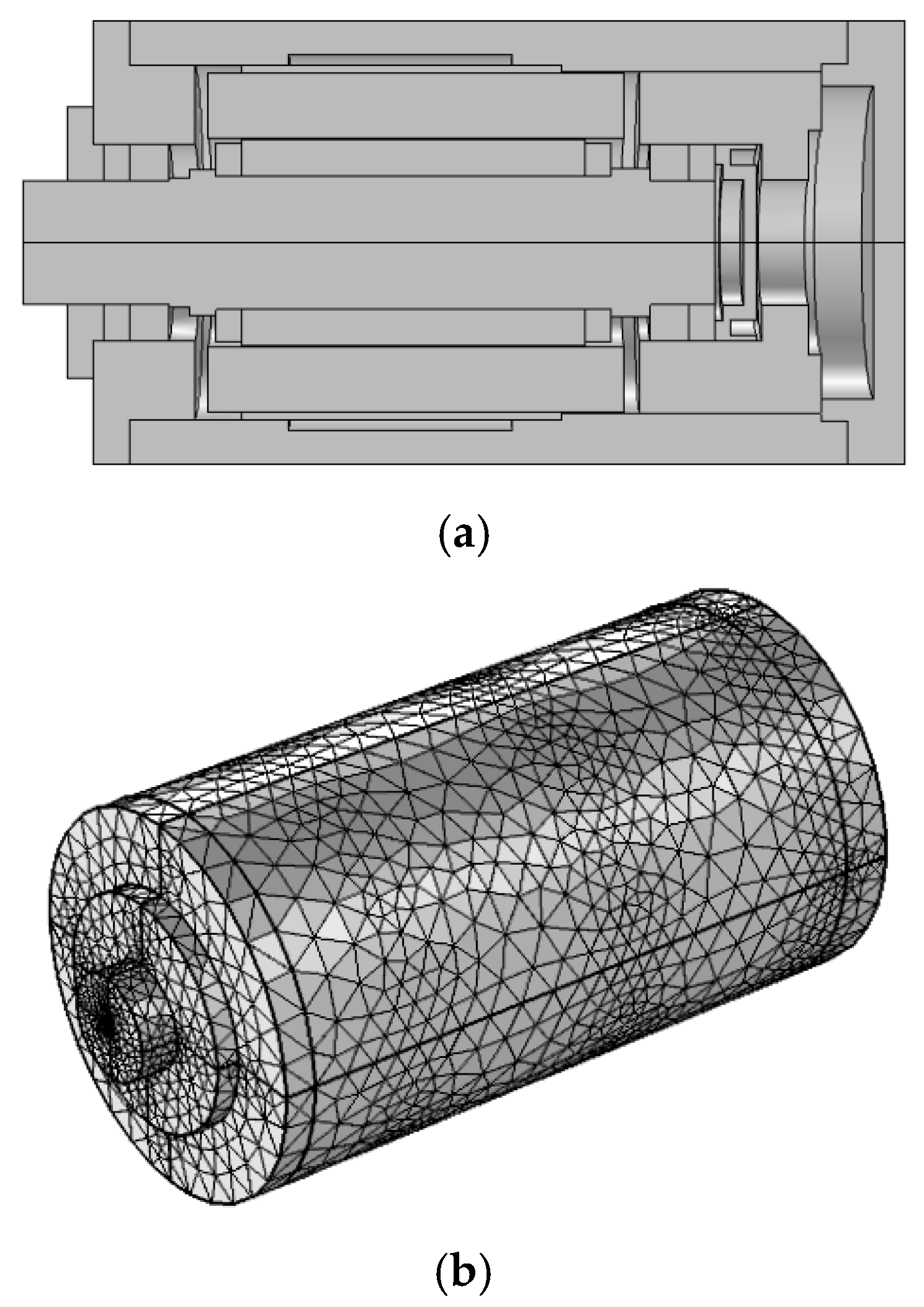
A finite element model of the 170MD30 motorized spindle (Luoyang Bearing Science & Technology Co., Ltd., Luoyang, Henan, China) was built in COMSOL( 5.2a, COMSOL AB, Tegnergatan 23, Stockholm, Sweden), and is shown in Figure 4 [24]. Table 1 lists the main parameters of the motorized spindle and Table 2 shows the material parameters of the model. In this model, the heating of the motor and bearings is considered. The angular contact ball bearing, rotor, and stator are assembled on the spindle while all screws, the vent, the oil hole, and other fine structures are ignored. The finite element model had 544,565 degrees of freedom in terms of temperature. The characteristic shape function was Lagrangian (square) and the GMRES iterative solver was used. The pre-smoothing scan type was Sor and the post-smoother scan type was Soru. The rough solver Pardis was used as well. An optimization model for the heat transfer coefficients of the motorized spindle was created in MATLAB (8.0.0.783, Mathworks, Natick, MA, USA, 2012) and the results of the iterations were used as boundary conditions of the finite element model to calculate the temperature field of the motorized spindle.
4.1. Acquiring Temperature Data
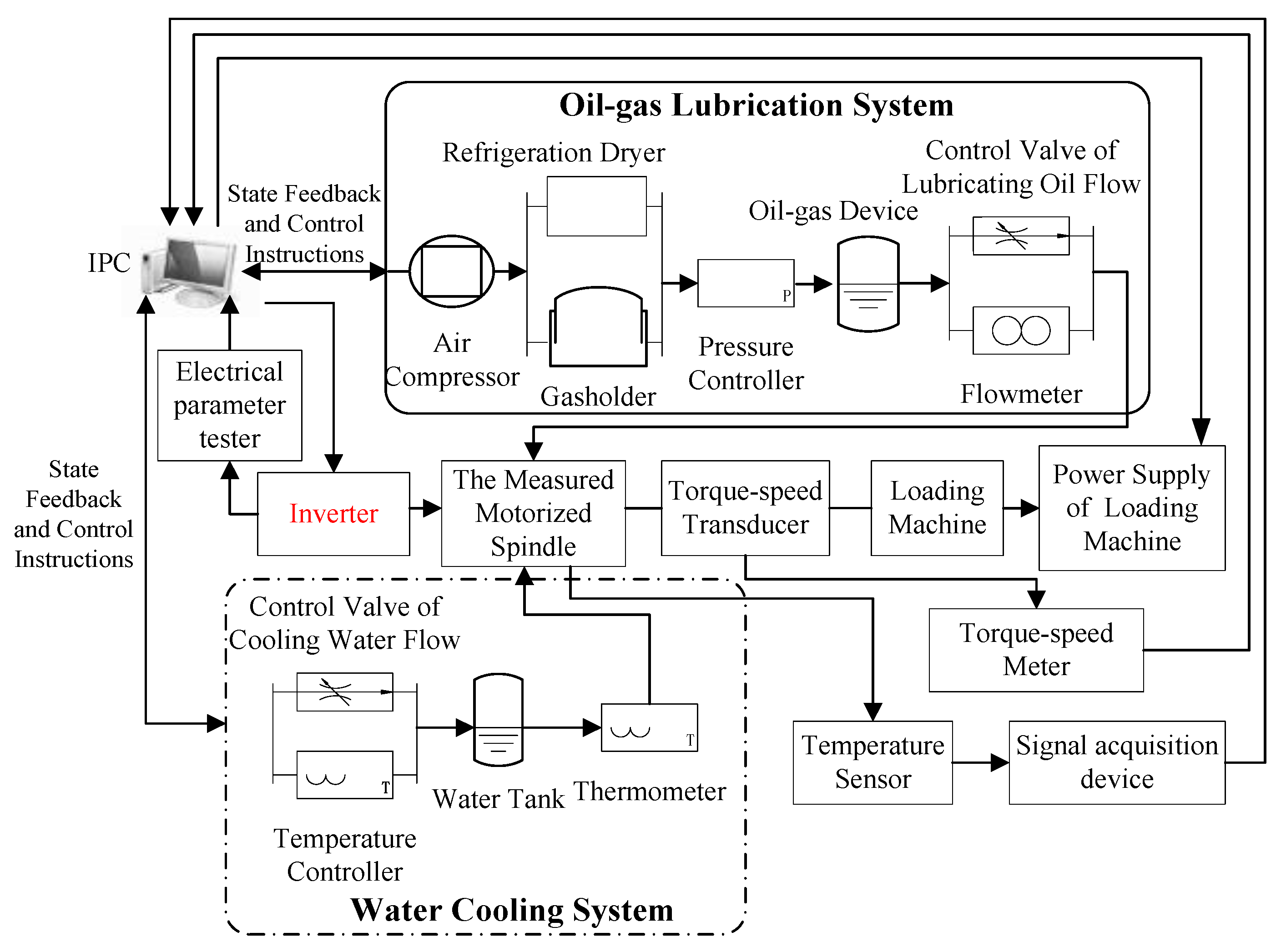
The prediction of the temperature field of the motorized spindle depends on the measured temperature at critical positions. The experimental system used is shown in Figure 5, and included an oil-gas lubrication system, a cooling system, a temperature test system, a loading system, and a speed control system. Air pressure, air temperature, and intervals of fuel supply could be monitored in the oil-gas lubrication system. The flow of cooling water and inlet temperature of the cooling system could also be controlled and monitored, but only the outlet temperature of the cooling system could. Consequently, the load and speed of the motorized spindle were also controllable and testable. The temperature test system consisted of temperature sensors placed on the surface of the motorized spindle. The surface temperature could be measured under different conditions involving the load, temperature of the cooling water, its flow rate, and the rate of flow of the lubricating oil using this test system.
4.2. Boundary Conditions of the Model
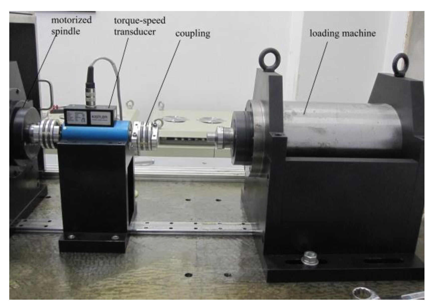
One of the boundary conditions of the prediction model is the rate of heat generation, which is calculated based on losses in the motorized spindle. The motor losses and bearing friction losses could be measured by the loss experimental device shown in Figure 6. The specific steps are as follows:
First, the loading machine and motorized spindle are connected, power supply to the motorized spindle is cut off, and it is rotated synchronously with the loading machine. At this point, the spindle exhibits only frictional loss, and the input power PJ1 of the loading machine is tested.
Second, the motorized spindle and loading machine are disconnected, where the latter has the same speed as in the first step, and the input power PJ2 of the loading machine is determined.
Third, the motorized spindle and loading machine are disconnected, where the former has zero load under the same speed as in the first step, the electrical parameter tester measures the input voltage and current of the motorized spindle, and the input power pin of the motorized spindle is obtained. At the same time, the torque/speed transducer can measure the output torque and speed of the motorized spindle, and the output power pout of the motorized spindle can be measured. The loss due to friction in the motorized spindle is
and the loss in the motor is
Usually, two-thirds of the motor loss occurs at the stator and one-third at the rotor [25]. Using the above method, the bearing loss, rotor loss, and stator loss of the 170MD30 motorized spindle (Luoyang Bearing Science & Technology Co., Ltd., Luoyang, Henan, China) were measured at 10,000 rpm and 15,000 rpm as shown in Table 3. All losses were converted into heat, and the rates of heat generation of the stator, rotor, and bearing are calculated as the boundary conditions of the finite element model.
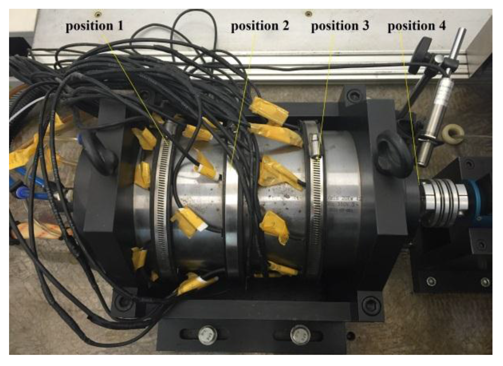
In the finite element model for the temperature field of the motorized spindle, another boundary condition is the heat transfer coefficient at the key positions. In this paper, the traditional empirical formula [26,27,28] was used to calculate the initial value of the heat transfer coefficient. The temperature-related test data for the optimization of the heat transfer coefficient were drawn from a temperature test system consisting of 31 temperature sensors placed on the surface of the motorized spindle. The arrangement of the temperature test is shown in Figure 7. Test position 1 was at the front bearing, position 3 at the rear bearing, position 2 was directly between the first two, and the end of the spindle formed test position 4. There were 10 thermocouples from test positions 1 to 3 that were uniformly distributed along the direction of the circumference. Moreover, an infrared thermal sensor was arranged at test position 4.
To prove the validity of the model, the temperature field of the motorized spindle was predicted under the following two conditions. The test parameters when the speed of the motorized spindle was 10,000 rpm included cooling water flow of 0.25 m3/h, an initial temperature of 12 °C of the cooling water, compressed air inlet pressure of 0.365 MPa, a fuel supply interval of 2 min, and compressed air temperature of 8 °C. The test parameters when the speed of the motorized spindle was 15,000 rpm featured cooling water flow of 0.32 m3/h, an initial temperature of 19 °C of the cooling water, compressed air inlet pressure of 0.35 MPa, a fuel supply interval of 3 min, and compressed air temperature of 18 °C. The initial and optimized values of the heat transfer coefficients are shown in Table 4.
4.3. Simulation
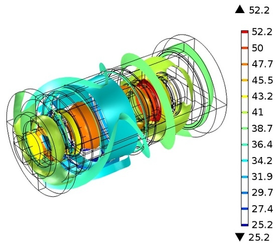
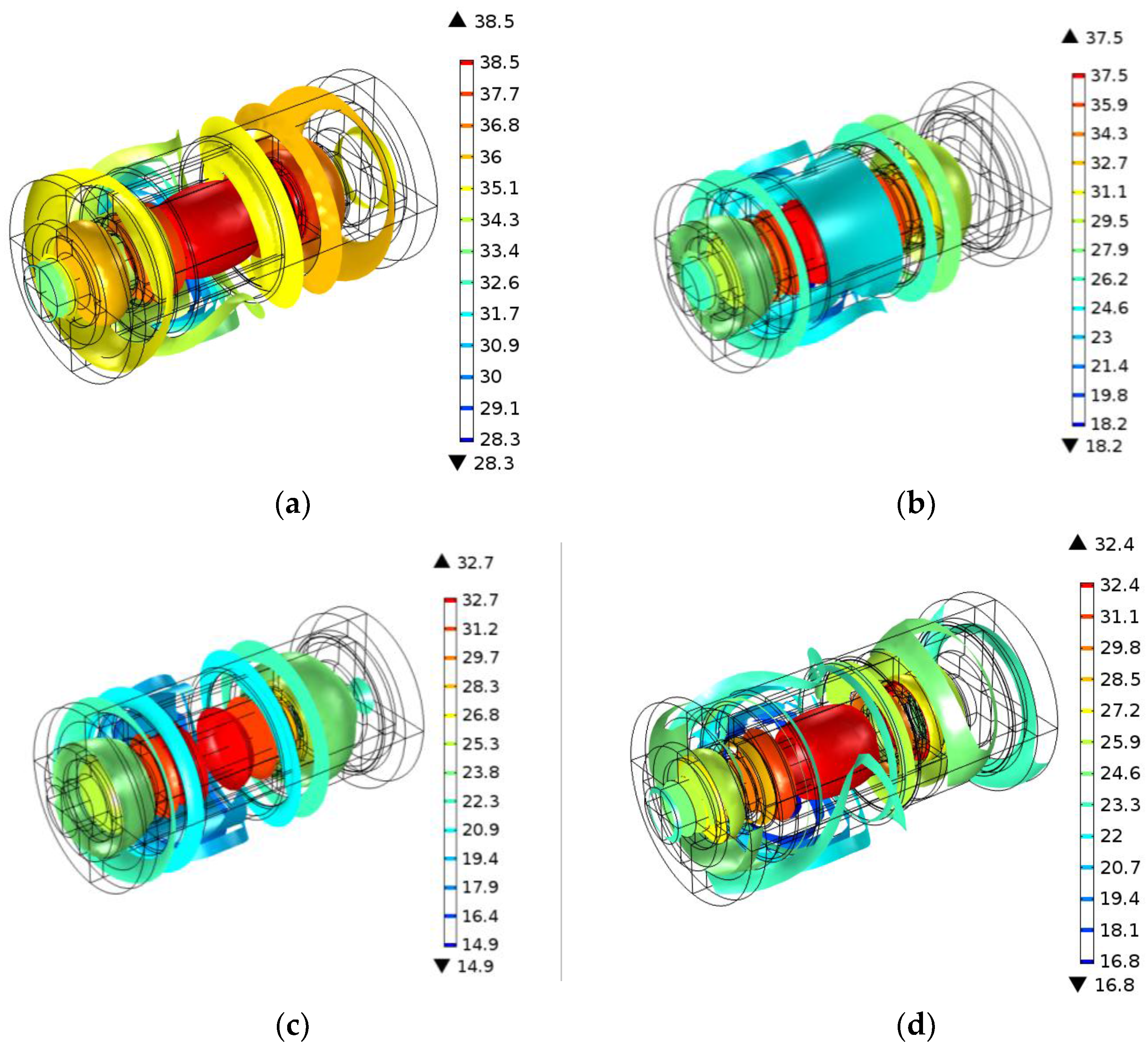
When the speed of the motorized spindle was 10,000 rpm, the isotherm was obtained from the temperature field prediction model to optimize the heat transfer coefficient as shown in Figure 8. Figure 8a,b show that the isotherms changed significantly with increase in the number of iterations of the heat transfer coefficient from 25 to 50. However, there was a slight change for iterations 75 to 100 as shown in Figure 8c,d. This implies that the results of the optimization of the heat transfer coefficient of the motorized spindle based on the genetic algorithm were convergent.
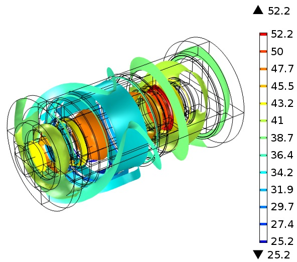
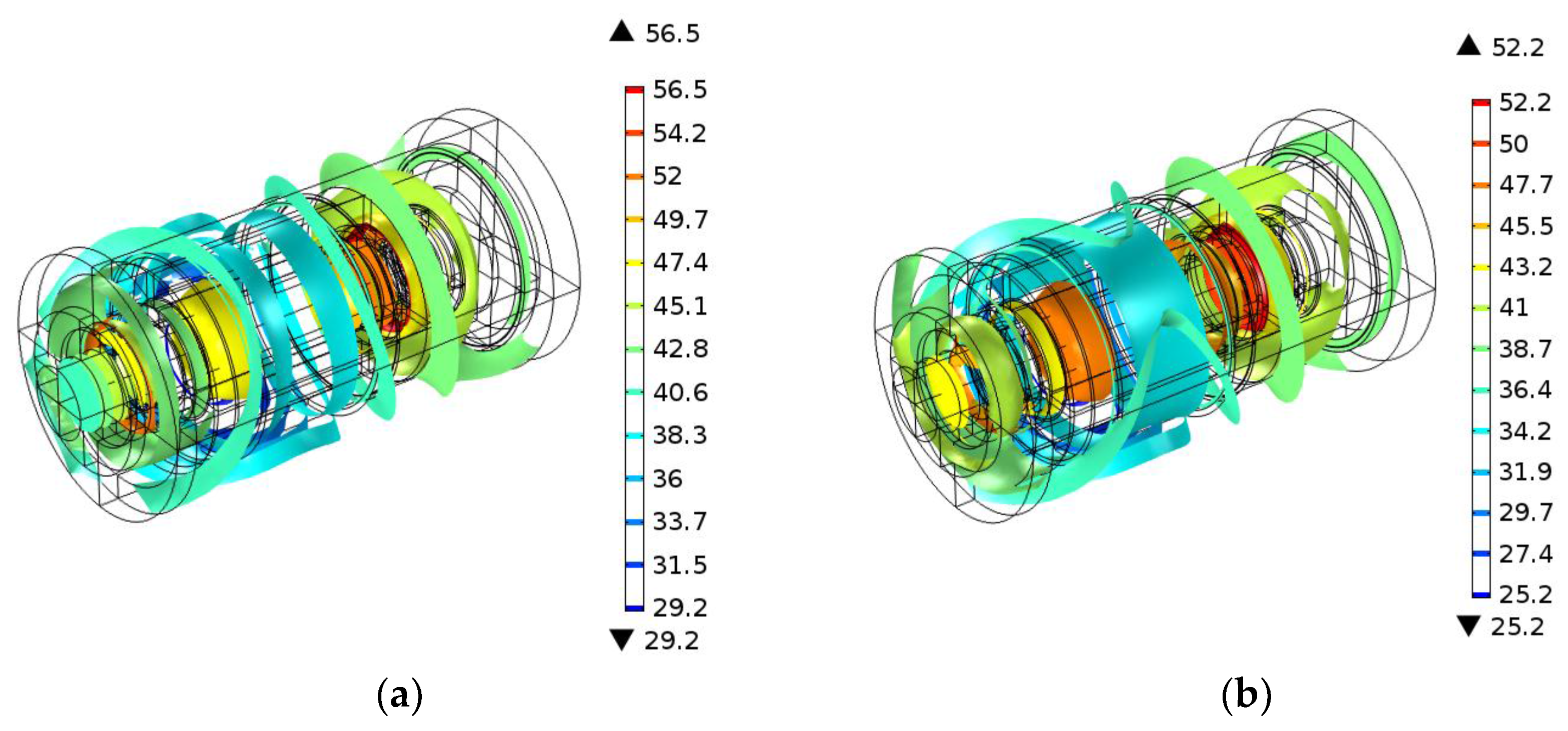
Similarly, Figure 9 shows the isotherm of the motorized spindle at 15,000 rpm. Figure 9a shows the isotherm for the initial values of the heat transfer coefficient and Figure 9b the isotherm when the coefficient was optimized over 100 iterations. Comparing Figure 9a,b, the effect of the heat transfer coefficient on the temperature field of the motorized spindle appeared to be significant.
4.4. Results and Comparison
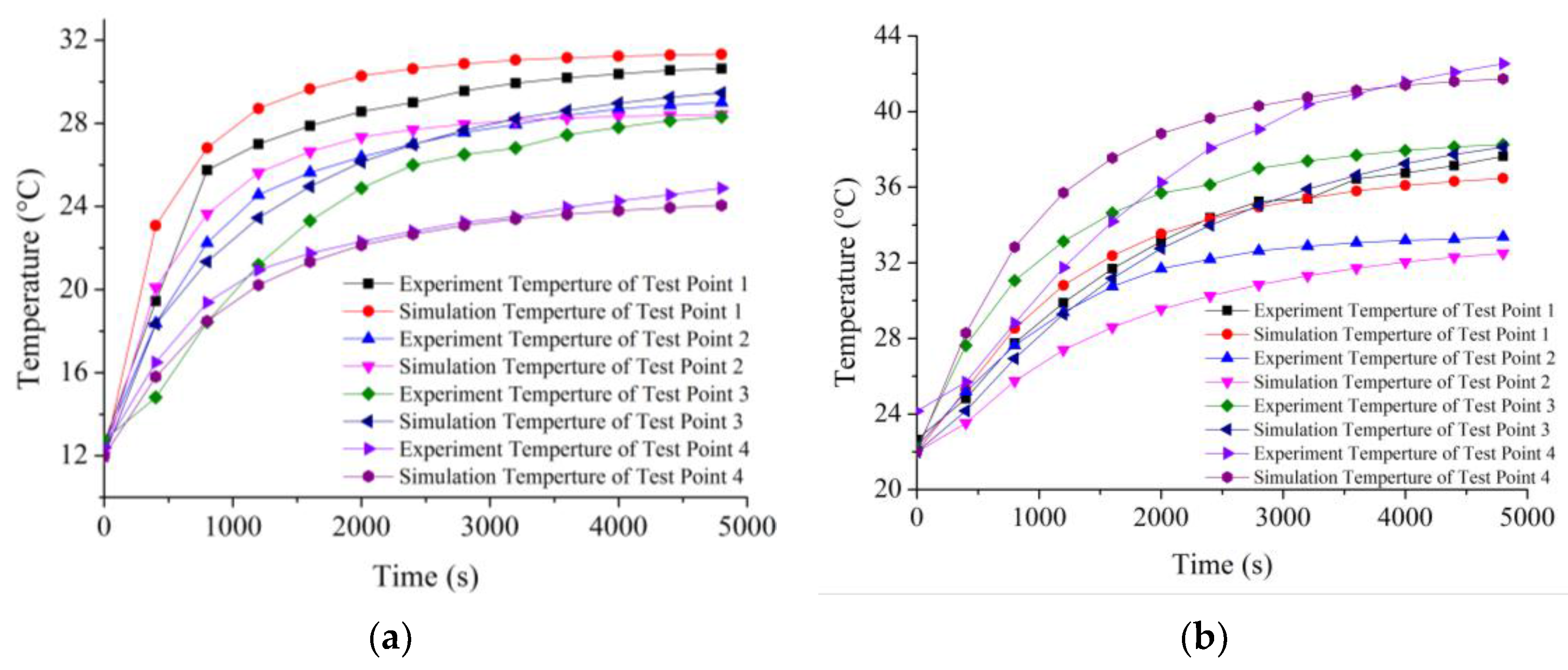
The simulation and monitored temperatures of the motorized spindle were compared to determine the accuracy of the model. Figure 10 shows this comparison after the heat transfer coefficient was optimized for 100 iterations. Figure 10a shows the results for 10,000 rpm and Figure 10b for 15,000 rpm. From Figure 10, it is clear that the predicted temperatures were very close to the experimental measurements for the latest time steps.
To further validate the temperature field of the prediction model of the motorized spindle, it is necessary to compare the simulation temperatures and test temperatures of other locations on the motorized spindle, and to calculate the overall error in the model. In the test system, the temperature of water at the outlet was assumed to be consistent with that of the water jacket at the given location. The temperature of water at the outlet can be determined; therefore, the temperature of the water jacket outlet could be used to determine the accuracy of prediction. The position of the outlet is shown in Figure 1. The relative mean error of the predictions of the model is
The variance s2 and standard deviation s of the prediction model are
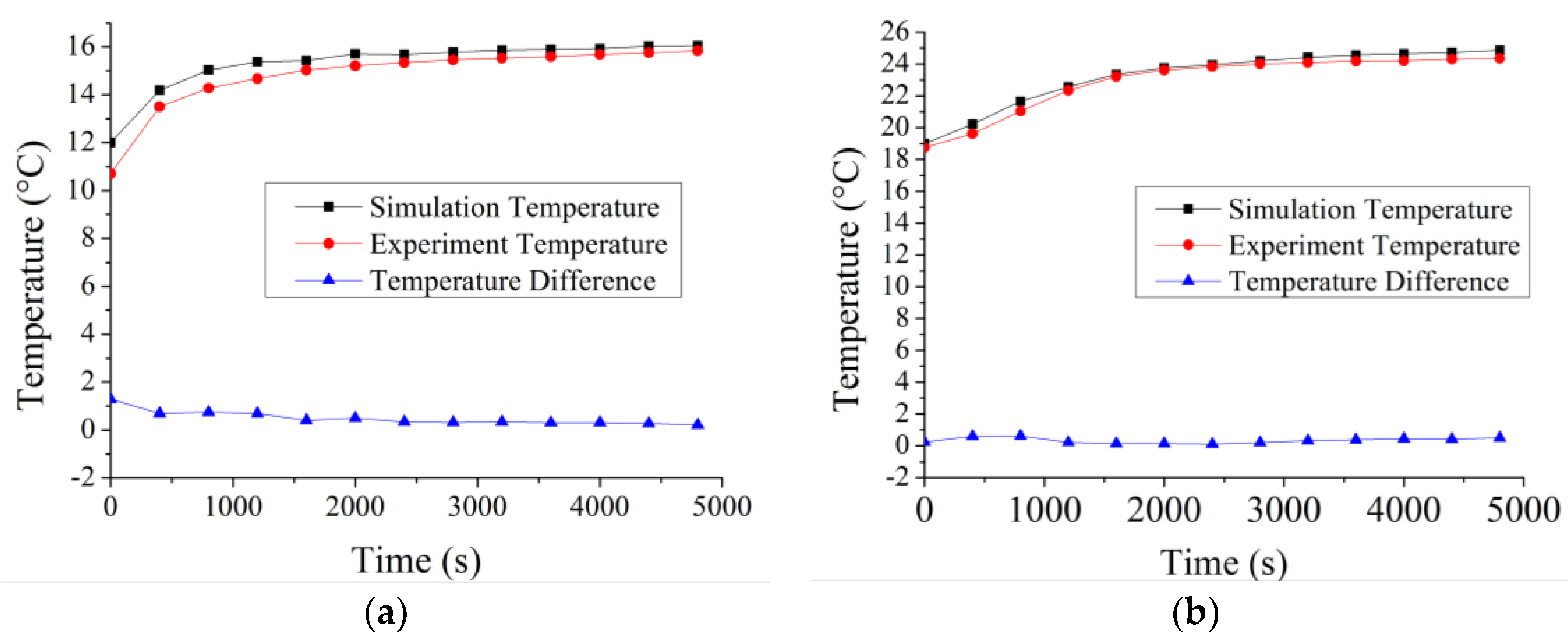
Figure 11 shows the predicted and measured differences in temperature at the water outlet. Both the table and the figure show data pertaining to the temperature of the water jacket outlet for spindle speeds of 10,000 rpm and 15,000 rpm. Also shown in Figure 11 is the prediction error in the model. According to Formulae (12)–(14), when the spindle speed was 10,000 rpm, the relative mean prediction error was 1.5%, variance was 2.87 × 10⁻⁴, and the standard deviation was 0.017. At 15,000 rpm, the prediction error was similarly small, the relative mean prediction error was 3.6%, variance was 2.0 × 10⁻³, and the standard deviation was 0.045.
5. Conclusions
In this paper, a hybrid model to predict the temperature field of a motorized spindle was proposed and experimentally verified. The model, based on the finite element method and temperature data collected at the surface of a motorized spindle, is dynamic, and can predict the characteristics of the temperature field distribution of the motorized spindle. The heat transfer coefficients were optimized based on the genetic algorithm by using surface temperature data as the boundary conditions of the model. A comparison of simulation analysis with experimental results showed that the model can predict the temperature field with high accuracy. The prediction of the temperature field of the motorized spindle can provide the basis for the assessment of its state. In future work, a prediction model of the thermal distortion of the motorized spindle based on the temperature field prediction model will be built to found the automatic compensation of thermal deformation.
Acknowledgments
The authors acknowledge support from the National Science Foundation (No. 51375317), the National Science Foundation (No. 51675353), the Liaoning Province Science Foundation (No. 2015020122), and the National (local) Joint Engineering Laboratory for Open Funds (sjsc-2015-6).
Author Contributions
L.Z. and H.S. conceived and designed the experiments; C.L. performed the experiments; Y.W. analyzed the data; K.Z. contributed materials/analysis tools; L.Z. wrote the paper.
Conflicts of Interest
The authors declare no conflict of interest.
References
- Zheng, C.D.; Si, Y.Y.; Jian, G.Y. Thermal Behavior Analysis and Thermal Error Compensation for Motorized Spindle of Machine Tools. Int. J. Precis. Eng. Manuf. 2015, 16, 1571–1581. [Google Scholar]
- Lin, C.W.; Lin, Y.K.; Chu, C.H. Dynamic Models and Design of Spindle-Bearing Systems of Machine Tools: A Review. Int. J. Precis. Eng. Manuf. 2013, 14, 513–521. [Google Scholar] [CrossRef]
- Bossmanns, B.; Tu, J.F. A Power Flow Model for High Speed Motorized Spindles-Heat Generation Characterization. J. Manuf. Sci. Eng. 2001, 123, 494–505. [Google Scholar] [CrossRef]
- Liu, Z.F.; Pan, M.H.; Zhang, A.P.; Ma, C.Y. Thermal Characteristic Analysis of High-speed Motorized Spindle System Based on Thermal Contact Resistance and Thermal-Conduction Resistance. Int. J. Adv. Manuf. Technol. 2015, 76, 1913–1926. [Google Scholar] [CrossRef]
- Ma, C.; Yang, J.; Zhao, L.; Mei, X.S.; Shi, H. Simulation and Experimental Study on the Thermally Induced Deformations of High-speed Spindle System. Appl. Therm. Eng. 2015, 86, 251–268. [Google Scholar] [CrossRef]
- Mayr, J.; Jedrzejewski, J.; Uhlmann, E.; Donmez, M.A.; Knapp, W.; Härtig, F.; Wendt, K.; Moriwaki, T.; Shore, P.; Schmitt, R.; et al. Thermal Issues in Machine Tools. CIRP Ann. Manuf. Technol. 2012, 61, 771–791. [Google Scholar] [CrossRef]
- Abele, E.; Altintas, Y.; Brecher, C. Machine Tool Spindle Units. CIRP Ann. Manuf. Technol. 2010, 59, 781–802. [Google Scholar] [CrossRef]
- Lin, C.W.; Tu, J.F. Model-based Design of Motorized Spindle Systems to Improve Dynamic Performance at High Speeds. J. Manuf. Process. 2007, 9, 94–108. [Google Scholar] [CrossRef]
- Hayato, Y.; Shimpei, M.; Hitoshi, H.; Hidenori, S. Minimizing Thermal Deformation of Aerostatic Spindle System by Temperature Control of Supply Air. JSME Int. J. 2006, 49, 606–611. [Google Scholar]
- Dave, S.; Douglas, H.; Mircea, P. Thermal Behaviour of Electrical Motors—An Analytical Approach. Available online: www.motor-design.com (accessed on 5 September 2009).
- Chao, J.; Wu, B.; Hu, Y.M. Heat Generation Modeling of Ball Bearing Based on Internal Load Distribution. Tribol. Int. 2012, 45, 8–15. [Google Scholar]
- Zahedi, A.; Movahhedy, M.R. Thermo-Mechanical Modeling of High Speed Spindles. Sci. Iran. 2012, 19, 282–293. [Google Scholar] [CrossRef]
- Jedrzejewski, J.; Kwasny, W.; Modrzycki, W. Limiting Precision Distortions in Spindle Unit of HSC Machining Centre. J. Mach. Eng. 2008, 8, 44–53. [Google Scholar]
- Jedrzejewski, J.; Kowal, Z.; Kwasny, W.; Modrzycki, W. Hybrid Model of High Speed Machining Centre Headstock. CIRP Ann. Manuf. Technol. 2004, 53, 285–288. [Google Scholar] [CrossRef]
- Jedrzejewski, J.; Kowal, Z.; Kwasny, W.; Modrzycki, W. High-speed Precise Machine Tools Spindle Units Improving. J. Mater. Process. Technol. 2005, 162–163, 615–621. [Google Scholar] [CrossRef]
- Jedrzejewski, J.; Kwasny, W. A Step towards the Holistic Modeling of the HSC Machining Centre and the Efficient Compensation of Its Errors. Int. J. Comp. Integr. Manuf. 2014, 28, 126–136. [Google Scholar] [CrossRef]
- Jedrzejewski, J.; Kwasny, W. Machine Tool Thermal Errors Reduction for 5-axis Machining of Aircraft Parts; Springer International Publishing: Garbsen, Germany, 2014; pp. 187–195. [Google Scholar]
- Neugebauer, R.; Ihlenfeldt, S.; Zwingenberger, C. An Extended Procedure for Connective Boundary Conditions on Transient Thermal Simulations of Machine Tools. Prod. Eng. 2010, 4, 641–646. [Google Scholar] [CrossRef]
- Holkup, T.; Cao, H.; Kolar, P.; Altinta, Y.; Zelený, J. Thermo-mechanical Model of Spindles. CIRP Ann. Manuf. Technol. 2010, 59, 365–368. [Google Scholar] [CrossRef]
- Zhang, M.H.; Yuan, S.M.; Liu, Q. Research on the Characteristics for High Speed Motorized Spindle Based on Finite Element Analysis. Manuf. Technol. Mach. Tool 2008, 29–32. [Google Scholar] [CrossRef]
- Chen, X.A.; Liu, J.F.; He, Y. Thermal Properties of High Speed Motorized Spindle and Their Effects. J. Mech. Eng. 2013, 49, 135–142. [Google Scholar] [CrossRef]
- Chen, X.A.; Zhang, P.; He, Y.; Liu, J.F. Power Flow Model of High-speed Motorized Spindles and Its Thermal Characteristics. Chin. J. Agric. Mach. 2013, 44, 250–254. [Google Scholar]
- Bi, J.T.; Chen, X.A.; Li, Y.S. Thermal Performance Analysis of High-speed High-performance Motorized Spindle. J. Mech. Transm. 2014, 35, 84–87. [Google Scholar]
- Zhang, L.X.; Yan, M.; Wu, Y.H.; Liu, T. Simulation analysis for two different materials motorized spindles with model coupled multi-physics. Mater. Res. Innov. 2015, 19 (Suppl. 5), 536–542. [Google Scholar]
- Ji, Y.J.; Wang, H.J.; He, D.X. Thermal Properties Analysis and Experiment Research for High Speed Motorized Spindle. Modul. Mach. Tool Autom. Manuf. Tech. 2014, 30–33. [Google Scholar] [CrossRef]
- Wang, Y.F.; Sun, Q.G.; Lv, H.B. The Temperature Field Comparison between Oil Gas Lubrication and Oil Injection Lubrication of Rolling Bearing. Lubr. Eng. 2014, 39, 66–70. [Google Scholar]
- Li, B.Z.; Feng, R.J.; Yang, J.G.; Wu, Z.P. Optimization Methods and Application Research of Stator Cooling Pipeline in High-speed Grinding Wheel System. Adv. Mater. Res. 2011, 199–200, 1579–1585. [Google Scholar] [CrossRef]
- Yang, S.Y.; Gao, X.H.; Liu, X.X. High-speed Motorized Spindle Water-cooling System Solid-liquid Coupling Heat Transfer Simulation Analysis. Mach. Tool Hydraul. 2011, 39, 102–104. [Google Scholar]
Figure 1.
Structure of the motorized spindle.

Figure 2.
Prediction model of the temperature field of the motorized spindle.

Figure 3.
Flowchart of genetic algorithm.

Figure 4.
Finite element model of the 170MD30 motorized spindle. (a) Geometrical model, (b) finite element analysis meshing model.
Figure 4.
Finite element model of the 170MD30 motorized spindle. (a) Geometrical model, (b) finite element analysis meshing model.

Figure 5.
Temperature testing system of the motorized spindle.

Figure 6.
Loss experimental device.

Figure 7.
Arrangement of temperature test positions.

Figure 8.
Isotherm of the motorized spindle at 10,000 rpm. (a) 25 iterations, (b) 50 iterations, (c) 75 iterations, (d) 100 iterations.
Figure 8.
Isotherm of the motorized spindle at 10,000 rpm. (a) 25 iterations, (b) 50 iterations, (c) 75 iterations, (d) 100 iterations.

Figure 9.
Isotherm of the motorized spindle at 15,000 rpm. (a) 0 iteration, (b) 100 iterations.

Figure 10.
Comparison between the simulation temperature and experimental measurements. (a) Spindle speed of 10,000 rpm, (b) Spindle speed of 15,000 rpm.
Figure 10.
Comparison between the simulation temperature and experimental measurements. (a) Spindle speed of 10,000 rpm, (b) Spindle speed of 15,000 rpm.

Figure 11.
The difference between the predicted and measured temperatures at the water outlet. (a) Spindle speed at 10,000 rpm, (b) Spindle speed at 15,000 rpm.
Figure 11.
The difference between the predicted and measured temperatures at the water outlet. (a) Spindle speed at 10,000 rpm, (b) Spindle speed at 15,000 rpm.


Table 1.
The main parameters of the motorized spindle.
| Parameters | Value |
|---|---|
| Rotor external diameter (mm) | 79.4 |
| Rotor iron core length (mm) | 112 |
| Stator internal diameter (mm) | 80 |
| Stator iron core length (mm) | 110 |
| Shaft maximum diameter (mm) | 56 |
| Shaft length (mm) | 170 |
| Motorized spindle external diameter (mm) | 266 |
| Bearing model | 7008C |
Table 2.
Parameters of materials of the model.
| Component | Material | Density (g/cm3) | Thermal Conductivity (W/(m·°C)) | Specific Heat Capacity (J/(kg·°C)) |
|---|---|---|---|---|
| Stator windings | Copper | 8.9 | 400.0 | 386.0 |
| Stator core | Silicon steel | 7.9 | 35.0 | 535.0 |
| Water jacket | 40Cr | 7.9 | 60.5 | 434.0 |
| Rotor bar | Cast aluminum | 2.8 | -- | 875.0 |
| Shaft | 40Cr | 7.9 | 60.5 | 434.0 |
| Coolant | Water | 1.0 | 0.6 | 4200.0 |
Table 3.
The heat rates of the motorized spindle.
| Speed (rpm) | Heat of Stator (w) | Heat of Rotor (w) | Bearing Heat (w) |
|---|---|---|---|
| 10,000 | 326.68 | 143.32 | 77.08 |
| 15,000 | 452.67 | 226.33 | 151 |
Table 4.
The heat transfer coefficients.
| Speed (rpm) | Initial Value (W/(m·°C)) | Optimized (W/(m·°C)) | ||||||||
|---|---|---|---|---|---|---|---|---|---|---|
| h1 | h2 | h3 | h4 | h5 | h1* | h2* | h3* | h4* | h5* | |
| 10,000 | 9.7 | 146.8 | 121.4 | 71.4 | 190.0 | 20.0 | 188.4 | 188.2 | 127.7 | 500.3 |
| 15,000 | 9.7 | 178.4 | 142.5 | 109.1 | 223.9 | 10.8 | 171.3 | 223.8 | 134.9 | 331.4 |
© 2017 by the authors. Licensee MDPI, Basel, Switzerland. This article is an open access article distributed under the terms and conditions of the Creative Commons Attribution (CC BY) license (http://creativecommons.org/licenses/by/4.0/).
Share and Cite
MDPI and ACS Style
Zhang, L.; Li, C.; Wu, Y.; Zhang, K.; Shi, H. Hybrid Prediction Model of the Temperature Field of a Motorized Spindle. Appl. Sci. 2017, 7, 1091. https://0-doi-org.brum.beds.ac.uk/10.3390/app7101091
AMA Style
Zhang L, Li C, Wu Y, Zhang K, Shi H. Hybrid Prediction Model of the Temperature Field of a Motorized Spindle. Applied Sciences. 2017; 7(10):1091. https://0-doi-org.brum.beds.ac.uk/10.3390/app7101091
Chicago/Turabian StyleZhang, Lixiu, Chaoqun Li, Yuhou Wu, Ke Zhang, and Huaitao Shi. 2017. "Hybrid Prediction Model of the Temperature Field of a Motorized Spindle" Applied Sciences 7, no. 10: 1091. https://0-doi-org.brum.beds.ac.uk/10.3390/app7101091
Note that from the first issue of 2016, this journal uses article numbers instead of page numbers. See further details here.