Fast Object Detection in Light Field Imaging by Integrating Deep Learning with Defocusing


State Key Laboratory of Mechanical System and Vibration, School of Mechanical Engineering, Shanghai Jiao Tong University, Shanghai 200240, China
*
Author to whom correspondence should be addressed.
Appl. Sci. 2017, 7(12), 1309; https://0-doi-org.brum.beds.ac.uk/10.3390/app7121309
Submission received: 12 October 2017
/
Revised: 8 December 2017
/
Accepted: 8 December 2017
/
Published: 17 December 2017
Abstract
:Although four-dimensional (4D) light field imaging has many advantages over traditional two-dimensional (2D) imaging, its high computation cost often hinders the application of this technique in many fields, such as object detection and tracking. This paper presents a hybrid method to accelerate the object detection in light field imaging by integrating the deep learning with the depth estimation algorithm. The method takes full advantage of computation imaging of the light field to generate an all-in-focus image, a series of focal stacks, and multi-view images at the same time, and convolutional neural network and defocusing are consequently used to perform initial detection of the objects in three-dimensional (3D) space. The estimated depths of the detected objects are further optimized based on multi-baseline super-resolution stereo matching while efficiency is maintained, as well by compressing the searching space of the disparity. Experimental studies are conducted to demonstrate the effectiveness of the proposed method.
1. Introduction
Recognizing objects and localizing them in three-dimensional (3D) space is one of the most significant topics for many fields, such as mobile robotics [1], security systems [2], etc. As the first step, appropriate sensors are required to capture the three-dimensional information of the world, in real time. A variety of techniques can be used to achieve the task, in which the 3D vision techniques, such as dynamic video processing and binocular stereo vision, are the most widely used [3]. It is well known that conventional images can only record two-dimensional (2D) spatial information of the scene while the angular information is barely recorded, which makes conventional 3D vision methods sensitive to the local structure of the scene, and may invalid in the presence of occlusion or at the region where the texture is low and repeated [4].
Light field imaging, as a relatively new technique, can record both the angular and spatial information of the scene in a single exposure [5]. It can either be recorded by a camera arrays or by a main lens combining with a micro lens arrays in front of the sensor [6]. Currently, along with the development of the manufacturing technology, consumer cameras that acquire light fields are starting to be commercially available in the market, such as Light [7] and Lytro [8]. The description of the light field was originally represented by a plenoptic function with five dimensions, and was reduced to four dimensions by Levoy and Hanrahan [9], who introduced two-plane parametrization to parametric the light field. Many advanced processing techniques was developed based on four-dimensional (4D) light field representation, such as post-digital refocusing, view point changing, aperture changing, and extending the depth of field at large aperture [10]. For 3D vision, light field imaging contains rich disparity and defocus information that can be used to evaluate the depth of the scene much more accurately than conventional stereo vision [10,11,12,13]. In light field imaging, depth estimation methods may generally be divided into two categories, including depth from stereo and depth from defocus. When comparing with stereo vision, the light field has unique ability to expand of the disparity space to a continuous space [11]. Hence, digital refocusing algorithm can be implemented and defocus response becomes additional cue to estimate the depth of the scene. For defocus cues, it avoids the occlusion problem [14] and matching ambiguity problems [15]. Traditionally, the defocus cue has been achieved through using multiple image exposures [16], which is however too slow to be used in recognition. Fortunately, the light field inherent refocusing ability can obtain a series of images that focus on different depth with highly parallel computation. This makes the fast estimation of the depth from defocus possible. Several research has also been conducted to combine both the disparity and defocus response so that the accuracy of the estimation can be further improved [17,18].
In view of the published literature, it is noticed that the most of the existing depth estimation methods for light field imaging are computationally too expensive to be used in real time application. Although much accurate estimation of the depth of the scene can be achieved comparing with conventional stereo vision, it may take several minutes for producing a single scene on a current general purpose computer, which is unacceptable for many application, such as augmented reality, object detection and tracking, and so on. In many applications, instead of the whole scene, high accurate depth estimation may only be required at specific regions, such as the regions where the objects are located. In such scenario, machine learning would become a good choice to recognize the objects, and sparse depth estimation can then be performed at the specified regions. In the recent decade, deep neural network has been being boom up in recognition and localization of objects from an image [19,20,21,22,23]. Therefore, this paper presents a hybrid method to accelerate the object detection in light field imaging to real time level. The main contribution of the presented work includes a framework for fast object detection and depth estimation in light field imaging by integrating the deep learning with the depth estimation algorithm. An algorithm is also presented to further optimize the depth of the detected object that is based on multi-baseline stereo matching while efficiency is maintained as well by compressing the searching space of the disparity using the defocus response. Details of the methods are presented and experimental studies are conducted to verify the effectiveness of the proposed method.
2. Methodology
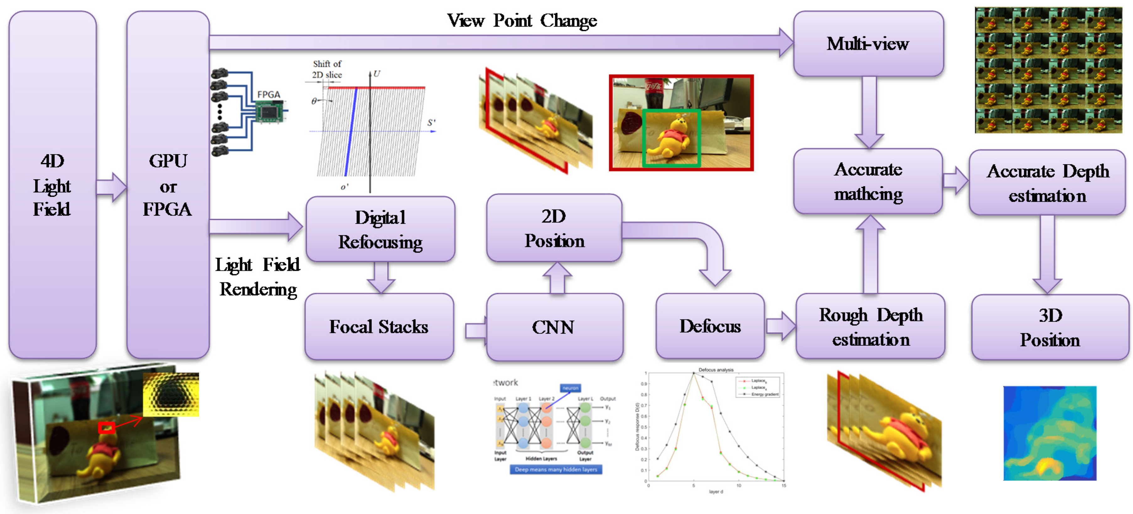
Figure 1 shows the framework of the proposed method. First of all, the scene that is captured by camera arrays or micro lens arrays are calibrated and parameterized by two-plane parametrization to form a light field. The parameterization of the light field in given in detail in Section 2.1. The captured light field is then used to generate three different kinds of images, including multi-view images, all-in-focus image, and a certain number of focal stacks by digital refocusing that can be processed with highly parallel computation on Graphics Processing Unit (GPU) or even Field Programmable Gate Array (FPGA), so as to achieve high efficient processing and imaging. Details of the digital refocusing is given in Section 2.2. Convolutional neural network (CNN) based detection and defocusing are then conducted to perform object detection and localization in 3D space. It is performed in three steps. In the first step, CNN is used to detect the objects on the all-in-focus image so that the positions of the objects in 2D space are determined. Occasionally, the detected objects may be hindered by something, such as tree. In such case, the detection of the objects may be fail on all in focus image. In such scenario, CNN should be conducted on all the focal stacks to enhance the capability of the detection. In the second step, the depths of the detected objects are evaluated by defocus response that is based the focal stacks. It is emphasized that, instead of estimating the depth of each pixel of the objects, only a depth is estimated for each object in this step since it is sufficient in most of scenarios in object detection and tracking. The details of the used CNN and defocus response are given in Section 2.3. In the third step, if it is necessary, the depths of the detected objects are further optimized via multi-baseline stereo matching, based on the multi-view images. Since the region and a depth are already assigned to each object by CNN and defocus response, the efficiency of the stereo matching can be improved from two aspects. Firstly, instead of the dense stereo matching, only the objects that are detected by the CNN are matched. Secondly, the searching space of the disparity is compressed by using the assigned depths in defocus response as initial value.
2.1. Two-Plane Parametrization of Light Field
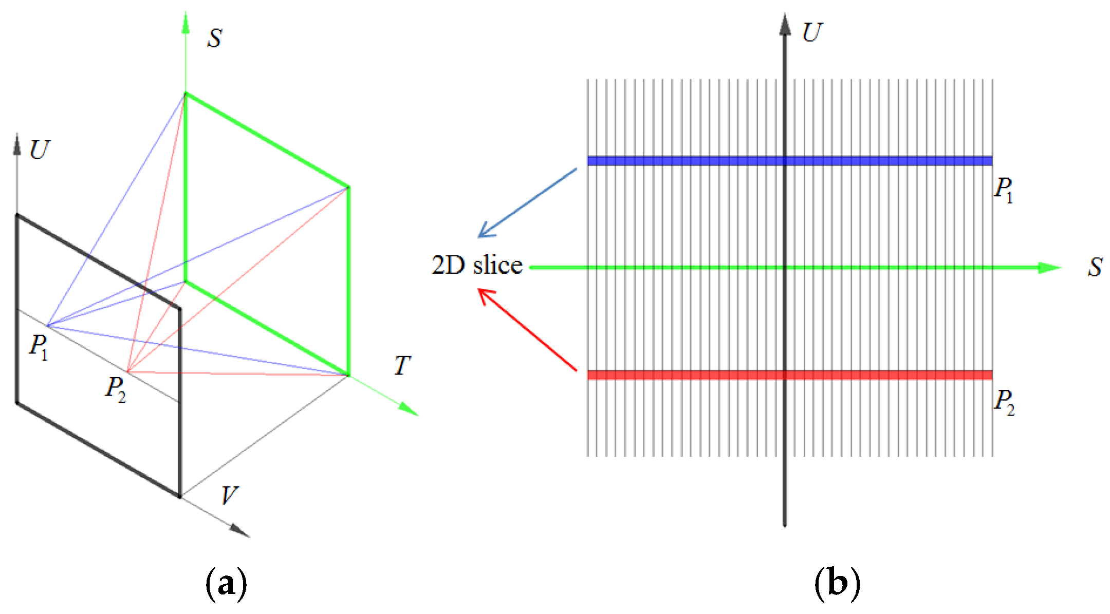
In geometric optics, the fundamental carrier of light is a ray, which can be described by plenoptic function with five parameters, including three coordinates and two angles [9]. The description can further be reduced to four dimension with the assumption that the radiance of the ray remains constant from point to point along its length [10]. Figure 2a shows the two-plane based four-dimensional parametrization of the light field. In two-plane parametrization, a ray is parameterized as L(u, v, s, t), where (u, v) are the coordinates of the view point in UV plane, and (s, t) are coordinates of the image point in the ST plane. Without loss of generality, the four dimensional representation can further be simplified to two-dimensional L(u, s) in Cartesian ray-space denoted as US plane as shown in Figure 2b. The ray depicted two planes is reduced to a point in the Cartesian ray-space US plane. The blue view point P1 and red view point P2 in Figure 2a represent corresponding color streak in Figure 2b, respectively. An arbitrary view point in a light field corresponds to a 2D slice in the US plane. Hence, by the use of the two-plane parametrization, the multi-view of the scene can be obtained by selecting different slices in US planes, and the all-in-focus image is just a special slice, of which u and v are the center of the UV plane [10]. Focal stacking is essentially a process of refocusing the scene at a series of different depths. Based on the two-plane parametrization, the irradiance of an arbitrary point in the image plane can be obtained by integrating the light passing through the entire UV plane, and the process of digital refocus is generally 2D slices shift in spatial dimension and integration in the angular dimension. This will be discussed in more detail in Section 2.2.
When considering the instruments used to capture the light field, camera array matches well with the principle that is presented in Figure 2. That is, each camera samples different views of the scenes corresponding to the UV plane. For the light field captured by micro lens array, the aperture is UV plane and the sensor is ST plane. Different views can be reconstructed by selecting corresponding pixel under each micro lens and putting them together.
2.2. Digtal Refocusing
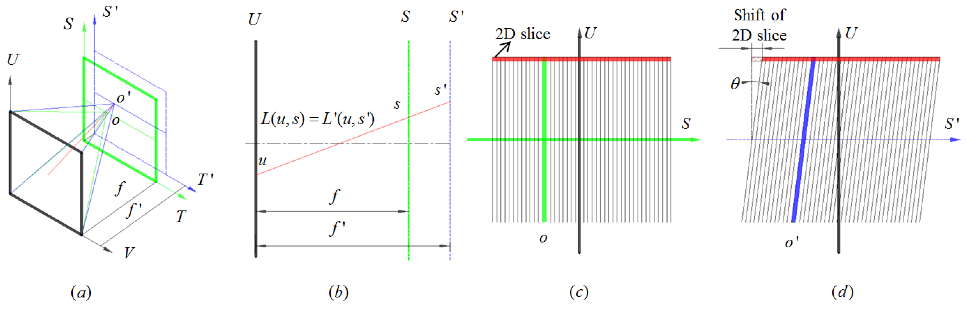
Digital refocusing is essentially a process of refocusing the scene at different depth based on the light field via pure digital computation. As shown in Figure 3a,b, the ray passes through UV plane to focus on the green ST plane. The distance between the two parallel planes is the focal length f and focal point o is on the ST plane. The irradiance of point o is obtained by integrating the entire UV plane as given by Equation (1) [6]:
Assuming that the image is refocused on the blue S′T′ plane which contains the focal point o′, the irradiance of the point o′ can be determined as follows [6].
Hence, by introducing a geometric constraint:
where f′ is the distance between the new image S′T′ plane and UV plane, Equation (2) can be rewritten as follows:
Equation (5) is the basis of the digital refocusing. The red 2D slice in Figure 3c,d and Equation (5) indicate that the process of digital refocus is the 2D slices shift on spatial dimension and integrate in the angular dimension. The refocusing depth is determined by a factor k defined as:
where θ denotes the slope of blue streak after shift the 2D slices. Hence, the shift distance ku of each slice has a linear relationship with angular dimension (u, v). Assuming that the number of focal stacks layers is fixed, then the shift distance of each slice is a constant value. Hence, the refocusing algorithm can be performed with parallel computation on GPU, or even FPGA, for real-time generation of a series of refocused image on different depths.
2.3. Object Detection and Defocus Response
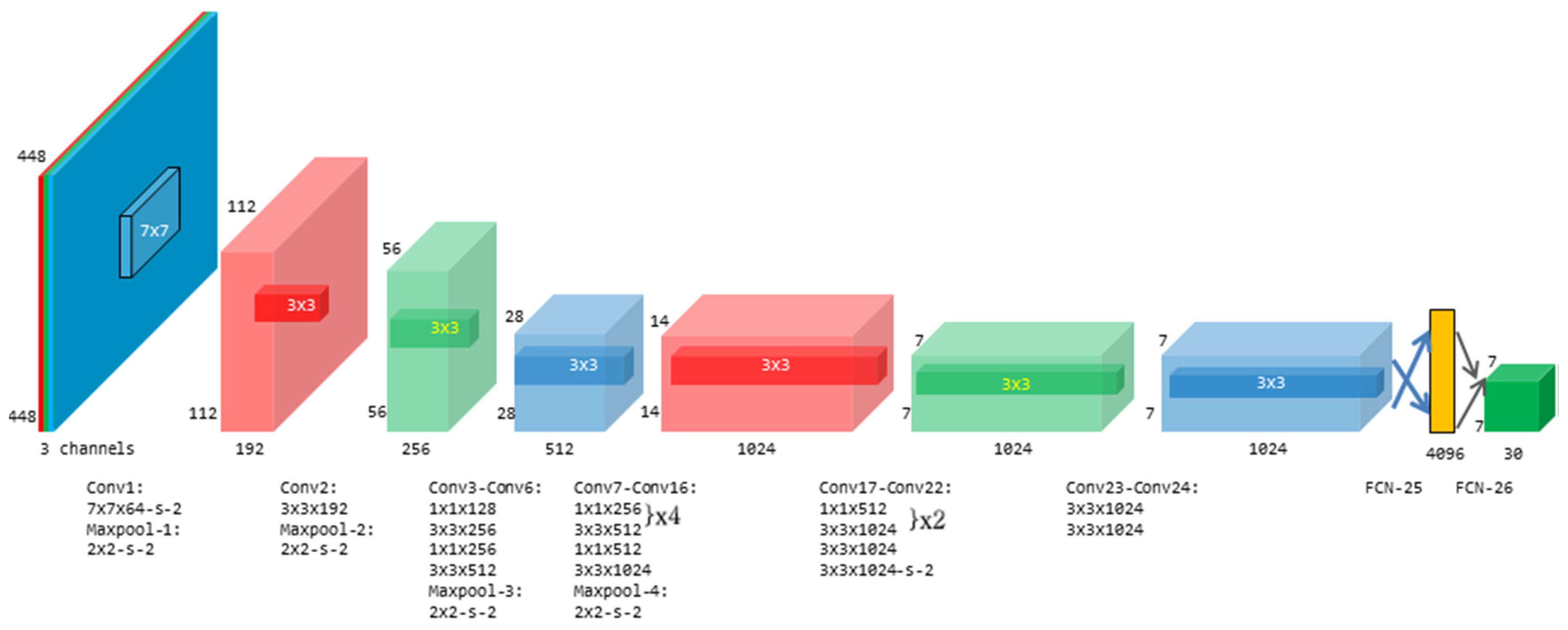
In the present study, a state-of-the-art deep learning method, named you only look once (YOLO), is used to detect the object on the all-in-focus image as well as the focal stacks [19]. Previous approaches, like region proposal convolutional neural network (R-CNN) [20,21], use region proposal method to choose candidate boxes in image, and take CNN to extract features to carry out the classification. While YOLO considers the object detection as a single regression problem and uses single CNN to deal with the regional proposal, classification, and bounding box locating as an end-to-end process, which makes it much computational efficient than other methods. The system of the YOLO is performed from three aspects [19]. Firstly, an image is input and is resized into 448 × 448. The resized image is divided into S*S grid and each grid is responsible for predicting whether the centers of the detected objects were located in this region.
Secondly, each grid containing the center of the detected object is used as initial condition to predict the bounding box for the corresponding object. Each bounding box contains five parameters, including x, y, w, h, and corresponding confidence. (x, y) are the shift of the center of bounding box from the corresponding grid, and the (w, h) are the dimension of the bounding box. The confidence means the possibility that there is a detected object and how precisely the box is located. Thirdly, the object contained in each box also needs to be classified by the confidence of every class Pr(Classi|Object). Hence, in the currently study, the CNN contains 26 layers, including 24 convolutional layers and two fully connected layers, as shown in Figure 4. The convolutional layers are made of two different kernels including 3 × 3 and 1 × 1 kernels. Besides, two boxes with different initial values are used to get a more precise box for complex scenario. The first FCN is a 4096 vector and the output is 7 × 7 × 30. Here 7 × 7 are the number of the grids. 30 corresponds to 20 classes and 10 parameters for the two boxes. The CNN is trained in two steps. In the first step, the first 20 convolutional layers, the average pooling layer and the fully connected layer are pre-trained by Image-Net 1000-class datasets [22] to get a robust and general feature extractor. In the second step, the final two layers are deleted and other four convolutional layers and two fully connected layers are trained together with pre-trained 20 convolutional layers by using the PASCAL [23]. More details of the CNN can be referred to [19].
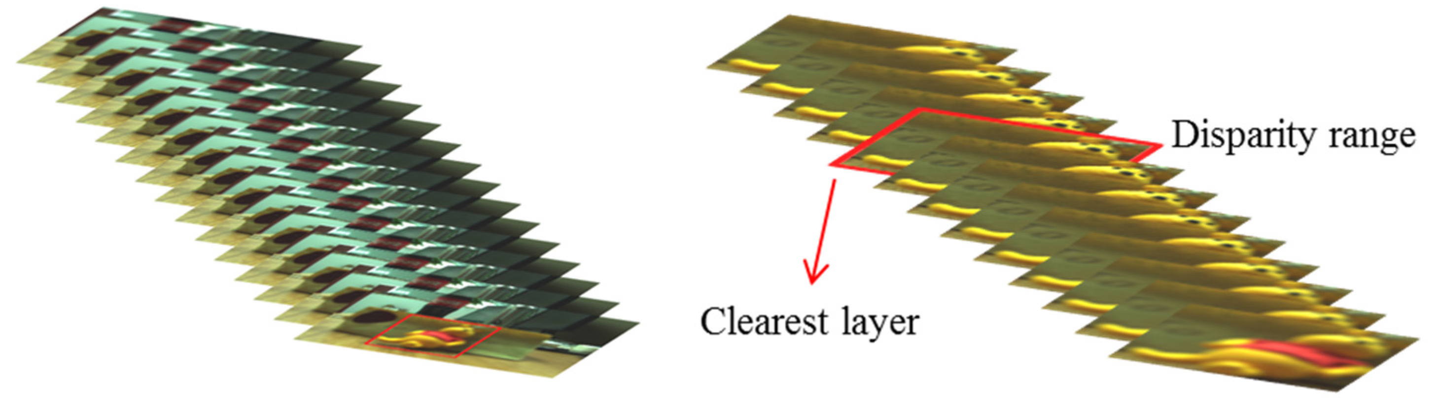
The depths of the detected objects are then estimated by the defocus response of the focal stacks at the bounding box. As shown in Figure 5, the bounding boxes are used to sub-sample the series of the focal stacks that were generated by digital refocusing, as presented in Section 2.2. Then, the sub-sampled regions are analyzed by defocus to find the clearest layer. For defocus analyzing, the gradient stacks can be computed via convolution. Different convolution kernels would result in different defocus response. It is stated in previous work [19] that the sum modified Laplacian (SML) operator has better performance than traditional operators, such as Sobel, Laplacian. This paper modifies the SML and present the sum squared modified Laplacian (SSML) operator to get sharper response at the focused layer, given by Equation (7):
Then, the defocus response D(d) is computed by:
where Id denotes the d-th layer of focal stacks. High response D(d) means that the corresponding layer is in focus. Figure 5 shows an example of depth estimation of the bear based on the defocus response of the focal stacks at the corresponding bounding box.
2.4. Refinement of the Depth Estimation
By taking the estimated depth by defocus response as input, multi-baseline stereo matching can be performed to further improve the accuracy of the depths of the object. When considering relatively narrow baseline of the multi-view images, phase shift based stereo depth estimation algorithm is adopted in the present study [12]. As discussed above, different 2D slices of the light field correspond to different views of the scene. Sub-pixel matching requires sub-pixel shift of the 2D slices to build the cost volume, and the corresponding phase shift in the 2D Fourier transform can be given by:
where the 2D shift vector denotes shift distance in 2D. The inverse Fourier transform is implemented to get accurate sub-pixel shift 2D slice
The cost volume C is built by two components, including the sum of the absolute differences (SAD) and the sum of the gradient differences (GRAD).
where l is cost label, is weight coefficient of SAD and GRAD. The SAD cost component is defined as:
where is the window to compute disparity, denotes the view point on UV plane, and denotes the center view point. The GRAD cost components is defined as:
where the is the x-directional gradient and is the y-directional gradient, is the weight coefficient of the two directions. Obviously, the closer to center view, the better the image is. Hence, is defined as
Every cost slice is refined through weighted median filtering in accordance with the center view image. The disparity map is then computed by winner-takes-all strategy.
3. Experimental Results
The proposed method was implemented on a NVIDIA GeForce 1080P GPU card (NVIDIA Corporate Headquarters, California, CA, USA) and tested on both a light field Benchmark dataset [10] and real world scenes, which are captured by a commercial light field camera Lytro Illum (Lytro, Inc., California, CA, USA) [8].
3.1. Benchmark Dataset Experiment
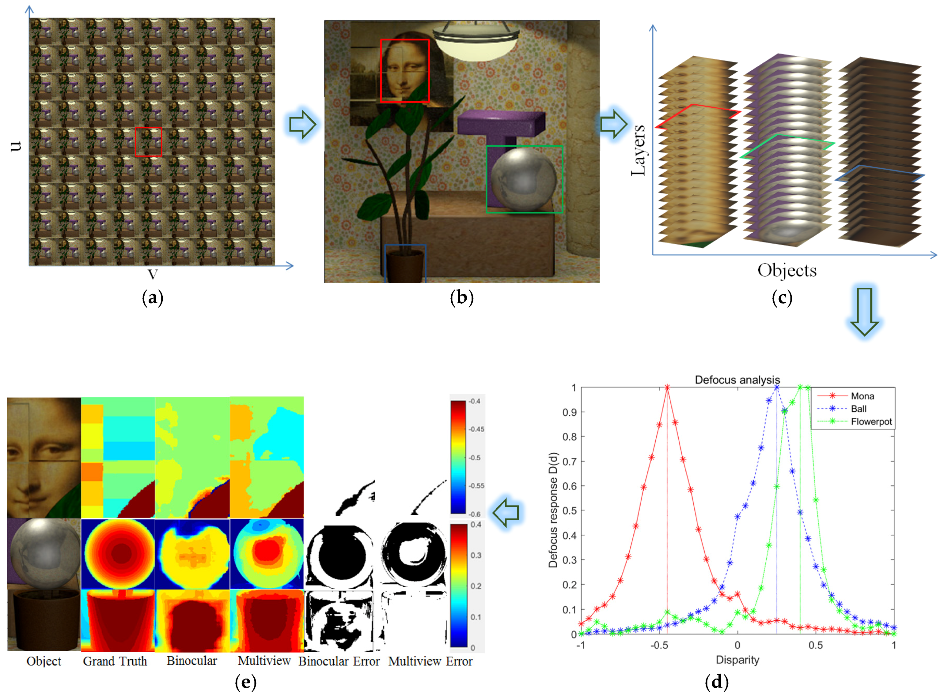
The proposed method is tested on a light field dataset, named Mona [10], in mainly in four steps, in accordance with the process given in Figure 1. In the first step, three different kinds of images are produced from the light field dataset, including multi-view images, as shown in Figure 6a, an all-in-focus image as shown in Figure 6b, and 41 layers of focal stacks in different depths as shown in Figure 6c. In the second step, CNN is used to perform the object detection on the all-in-focus image. A total of three objects are detected, including Mona, a ball, and a flowerpot. The identified regions as highlighted by the bounding box in Figure 6b are then used to sample the 21 focal, as shown in Figure 6c. The depths of the identified objects are determined by analyzing the defocus of the corresponding focal stacks. Figure 6d shows the defocus response of the three objects based on sum squared modified Laplacian (SSML) operator. It is clearly illustrated from the results that the defocus response has very sharp response at the focused layer, which can be used to determine the depths of the corresponding objects with high robustness. The depths of Mona, ball, and flowerpot are identified to be −0.45, 0.25, and 0.4, respectively, according to the defocus response. It is emphasized that, only a single value was assigned for each object in the present study. Although focal stacks can achieve much better resolution by more comprehensive defocusing analysis, the process would take long time for the computation and would be not able to perform in real time. In the current version, the proposed method can achieve around 10 frame rate on NVIDIA GeForce 1080P GPU card. The main time consumption is in the object detection process.
In case of the scenarios which require depth estimation per pixel, multi-baseline stereo matching can be performed. One of the problems anticipated in the present study is that dense depth estimation inevitably cost expense computation in stereo matching. As a result, although currently available methods can achieve very high matching accurate in light field image comparing with conventional stereo matching, it would take relatively long time for the depth estimation, normally in several or even dozens of seconds [12,13,14], which hinders the light field imaging to be used in many applications. For the proposed method, since initial depths are already estimated by defocus response for every detected object in the third step, the efficiency of the stereo matching can be dramatically improved by shrinking the searching space of the disparity in the fourth step. Figure 6d shows the depths of the objects evaluated by multi-baseline phase shifting stereo matching based on light field. It can be inferred from the results that the depths estimated by the stereo matching generally match well with that are obtained by the defocusing. The results are also compared with conventional binocular stereo matching method [4]. A summary of the comparison is shown in Table 1. It is inferred from the results that the multi-baseline phase shifting stereo matching has much better performance than conventional stereo matching especially at the occlusion regions, such as the boundaries of flowerpot and the ball. However, the multi-view stereo matching inevitably requires much more time for the computation than binocular stereo matching. Currently, the proposed method can achieve around 5 frame rate on NVIDIA GeForce 1080P GPU card. On the other hand, it is also shown from the results that both of the methods have worse performance in matching the ball due to the high spot and low texture. However, the principle of the defocusing makes it has less influence on these factors. In such a scenario, instead of a detailed depth estimation of the object by stereo, a single value of depth estimation by defocusing would be better for object localization.
3.2. Real Word Experiment
The proposed method is also used in real scene to further examine the validity in object detection. The light field data is collected by a commercial light field camera named Lytro Illum [8], and the data is decoded by the procedure given by Dansereau(Lytro, Inc., California, CA, USA) [8]. Before the processing, it is necessary to correct the color of the image by gamma correction.
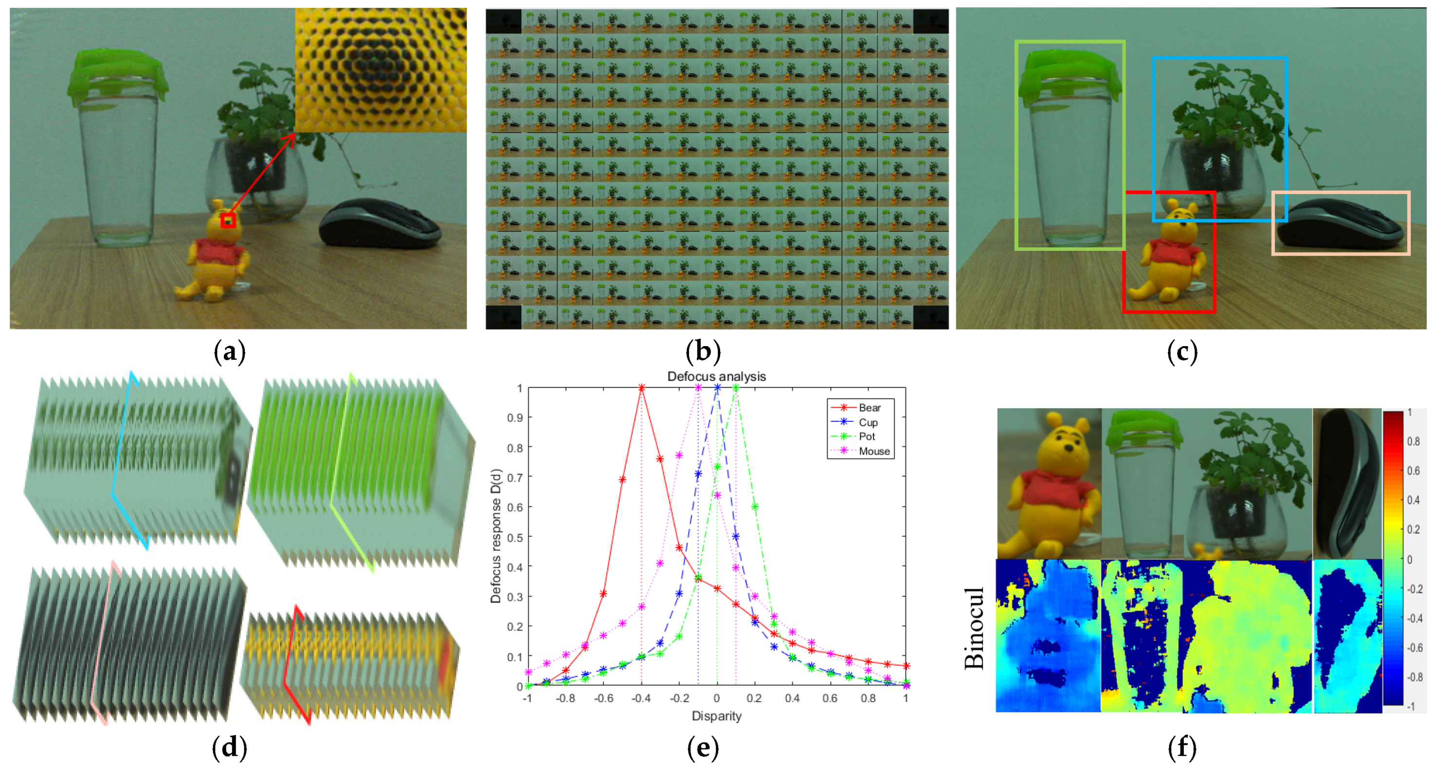
Figure 7 presents the process of the experiment. First of all, the 4D light field was taken by Lytro Illum, and the raw data is shown in Figure 7a. 4D light field data can be presented by a 4D vector contains (u,v,s,t) after decoded the raw data. Three different kinds of images are produced from the 4D light field data, including the 13 × 13 multi-view images, as shown in Figure 7b, the all-in-focus image, as shown in Figure 6c, and the focal stacks as shown in Figure 7d. The CNN is then used to detect the objects on the all-in-focus image. As shown in Figure 7c, four objects are detected. The focal stacks are then trimmed by the bounding box of the detected objects, and are used to estimate the depths of the objects based on defocus response. When considering that the disparity range between two adjacent views is from −1 pixel to 1 pixel [8], subpixel shift should be performed if more than two layers of the focal stacks are required. Based the theory of Discrete Fourier Transform (DFT), continuous movement of images can be implemented. In the present study, 0.1 pixel shift is implemented between two adjacent views. Hence, 21 layers of focal stacks are used to analyze the defocus response of the detected objects.
The defocus response is analyzed by the gradient of the focal stacks by SSML operator, as shown in Figure 7e. It is clearly seen from the results that the focused layer has very sharp response can easily and robustly be detected from the series of focal stacks, as shown in Figure 7d. The detected layers are marked with colored rectangles. Then, by taking the estimated depth by defocus response as input, multi-baseline stereo matching is performed on each bounding box, and the results are shown in Figure 7f. It is shown from the disparity maps that the cup and pot have very large percentage of mismatched pixels since they have low texture and are semitransparent. In such a scenario, the estimated depth maps are completely useless since it is almost impossible for a computer to judge which part of the depth map is correct or not. However, for the defocus response, the gradient of high frequency region like edges of the object can be much bigger than the low frequency region like low texture region. Hence, the defocus response can still be very sharp at the focused layer, which makes the defocus response based depth estimation method, although being relatively rough, is still very robust even for those objects which has low texture and are semitransparent.
4. Conclusions
This paper presents an efficient method for object detection using light field imaging. A hybrid method is presented to accelerate the object detection process by integrating the deep learning with the depth estimation algorithm. The method takes full advantage of the computation imaging of light field to generate an all-in-focus image, multi-view image, and a series of focal stacks at the same time. CNN based object detection, defocus analysis, and stereo matching are then consequently used to perform the detection of the objects in 3D space. Experimental study has been conducted to verify the validity of the proposed method. When comparing with conventional stereo imaging, the light field imaging has unique capability in re-focusing, which makes it possible to estimate the object in the scene based on defocus response. This would be the most important technical merit of the light field imaging in object detection when comparing with conventional stereo imaging, especially in detecting semitransparent and low textured objects. Further research will be conducted on integrating both the stereo disparity and defocus response in a single CNN for more efficient object detection.
Acknowledgments
The work was substantially supported by the National Natural Science Foundation of China (Grant No. 51505404, and No. 51675456), and Shanghai Pujiang Program of China (Grant No. 16PJ1404300).
Author Contributions
Mingjun Ren, Runxing Liu and Haibo Hong conceived and designed the experiments and wrote the paper; Jieji Ren and Gaobo Xiao performed the experiments and analyzed the data.
Conflicts of Interest
The authors declare no conflict of interest.
References
- Lowe, D.G. Object recognition from local scale-invariant features. In Proceedings of the Seventh IEEE International Conference on Computer Vision, Kerkyra, Greece, 20–27 September 1999; Volume 2, pp. 1150–1157. [Google Scholar]
- Kim, S.; Yuseok, B.; Sangyoun, L. Face liveness detection using a light field camera. Sensors 2014, 14, 22471–22499. [Google Scholar] [CrossRef] [PubMed]
- Karabegovic, I.; Vojic, S.; Dolecek, V. 3D vision in industrial robot working process. In Proceedings of the 2006 12th International Power Electronics and Motion Control Conference, Portoroz, Slovenia, 30 August–1 September 2006; pp. 1223–1226. [Google Scholar]
- Scharstein, D.; Szeliski, R. A taxonomy and evaluation of dense two-frame stereo correspondence algorithms. Int. J. Comput. Vis. 2002, 47, 7–42. [Google Scholar] [CrossRef]
- Georgiev, T.; Lumsdaine, A. Focused plenoptic camera and rendering. J. Electron. Imaging 2010, 19, 021106. [Google Scholar]
- Ng, R. Digital Light Field Photography. Ph.D. Dissertation, Department of Computer Science, Stanford University, Stanford, CA, USA, 2006. [Google Scholar]
- THE LIGHT L16 CAMERA. Available online: https://light.co/camera (accessed on 14 November 2017).
- LYTRO SUPPORT. Available online: https://illum.lytro.com/zh/ (accessed on 14 November 2017).
- Levoy, M.; Hanrahan, P. Light field rendering. In Proceedings of the International Conference on Computer Graphics and Interactive Techniques, New Orleans, LA, USA, 4–9 August 1996; pp. 31–42. [Google Scholar]
- Dansereau, D.G.; Pizarro, O.; Williams, S.B. Decoding, calibration and rectification for lenselet-based plenoptic cameras. In Proceedings of the 2013 IEEE Conference on Computer Vision and Pattern Recognition, Portland, OR, USA, 23–28 June 2013; pp. 1027–1034. [Google Scholar]
- Adhikarla, V.K.; Sodnik, J.; Szolgay, P. Exploring direct 3D interaction for full horizontal parallax light field displays using leap motion controller. Sensors 2015, 15, 8642–8663. [Google Scholar] [CrossRef] [PubMed]
- Wanner, S.; Goldluecke, B. Globally consistent depth labeling of 4D light fields. In Proceedings of the 2012 IEEE Conference on Computer Vision and Pattern Recognition, Providence, RI, USA, 16–21 June 2012; pp. 41–48. [Google Scholar]
- Wang, T.; Efros, A.A.; Ramamoorthi, R. Occlusion-aware depth estimation using light-field cameras. In Proceedings of the 2015 IEEE Conference on International Conference on Computer Vision, Santiago, Chile, 7–13 December 2015; pp. 3487–3495. [Google Scholar]
- Jeon, H.; Park, J.; Choe, G.; Park, J.; Bok, Y.; Tai, Y.; Kweon, I.S. Accurate depth map estimation from a lenslet light field camera. In Proceedings of the 2015 IEEE Conference on Computer Vision and Pattern Recognition, Boston, MA, USA, 7–12 June 2015; pp. 1547–1555. [Google Scholar]
- Nayar, S.K.; Watanabe, M.; Noguchi, M. Real-time focus range sensor. IEEE Trans. Pattern Anal. Mach. Intell. 1996, 18, 1186–1198. [Google Scholar] [CrossRef]
- Subbarao, M.; Liu, Y.F. Accurate reconstruction of three-dimensional shape and focused image from a sequence of noisy defocused images. Proc. SPIE Three Dimens. Imaging Laser-Based Syst. Metrol. Insp II 1996, 2909, 178–191. [Google Scholar]
- Watanabe, M.; Nayar, S.K. Rational filters for passive depth from defocus. Int. J. Comput. Vis. 1998, 27, 203–225. [Google Scholar] [CrossRef]
- Tao, W.; Hadap, S.; Malik, J.; Ramamoorthi, R. Depth from combining defocus and correspondence using light field cameras. In Proceedings of the 2013 IEEE Conference on IEEE International Conference on Computer Vision, Sydney, Australia, 1–8 December 2013; pp. 673–680. [Google Scholar]
- Szegedy, C.; Liu, W.; Jia, Y.; Sermanet, P.; Reed, S.; Anguelov, D.; Erhan, D.; Vanhoucke, V.; Rabinovich, A. Going deeper with convolutions. In Proceedings of the 2015 IEEE Conference on Computer Vision and Pattern Recognition, Boston, MA, USA, 7–12 June 2015; pp. 1–9. [Google Scholar]
- Redmon, J.; Divvala, S.K.; Girshick, R.B.; Farhadi, A. You only look once: unified, real-time object detection. In Proceedings of the 2016 IEEE Conference on Computer Vision and Pattern Recognition, Las Vegas, NV, USA, 27–30 June 2016; pp. 779–788. [Google Scholar]
- Ren, S.; He, K.; Girshick, R.; Sun, J. Faster R-CNN: Towards real-time object detection with region proposal networks. IEEE Trans. Pattern Anal. Mach. Intell. 2017, 39, 1137. [Google Scholar] [CrossRef] [PubMed]
- IMAGENET. Available online: http://www.image-net.org/ (accessed on 15 December 2017).
- THE PASCAL VISUAL OBJECT CLASSES HOMEPAGE. Available online: http://host.robots.ox.ac.uk/pascal/VOC/voc2007/index.html (accessed on 15 December 2017).
Figure 1.
Framework of the proposed method.

Figure 2.
Two-plane parametrization of light field. (a) Two-plane parametrization; (b) two-dimensional (2D) Cartesian ray-space diagram.
Figure 2.
Two-plane parametrization of light field. (a) Two-plane parametrization; (b) two-dimensional (2D) Cartesian ray-space diagram.

Figure 3.
The principle of digital refocusing based on two-plane parametrization of light field. (a) Refocusing denoted by two-plane parametrization; (b) Representing the four-dimensional (4D) light field by 2D (u, s); (c) Sampling of radiance before refocusing which focus on ST plane; and, (d) Sampling of radiance after refocusing which focus on S′T′ plane.

Figure 4.
The Architecture of the convolutional neural network.

Figure 5.
An illustration of depth estimation based on the defocus response of the focal stacks.

Figure 6.
Result of Mona synthetic 4D light. (a) The input 4D light field. (b) Identified objects in all focus image. (c) Focal stacks of object regions. (d) Depth estimation by defocus analysis of the down sampled focal stacks. (e) Depth estimation of objects by stereo matching.
Figure 6.
Result of Mona synthetic 4D light. (a) The input 4D light field. (b) Identified objects in all focus image. (c) Focal stacks of object regions. (d) Depth estimation by defocus analysis of the down sampled focal stacks. (e) Depth estimation of objects by stereo matching.

Figure 7.
Application of the proposed method in real scene. (a) Light field data collected by Lytro Illum. (b) The decoded light field data. (c) Identified objects on all-in-focus image. (d) Focal stacks of object regions. (e) Depth estimation by defocus response. (f) Depth estimation per pixel by multi-baseline stereo matching.


Table 1.
A summary of the stereo matching results of the identified objects.
| Object | Views | Resolution | Percentage of Inaccurate Matching | |
|---|---|---|---|---|
| Binocular Stereo | Multi-View Stereo | |||
| Mona | 9 × 9 | 93 × 453 | 3% | 1% |
| Ball | 9 × 9 | 190 × 181 | 57% | 52% |
| Flowerpot | 9 × 9 | 113 × 95 | 39% | 5% |
© 2017 by the authors. Licensee MDPI, Basel, Switzerland. This article is an open access article distributed under the terms and conditions of the Creative Commons Attribution (CC BY) license (http://creativecommons.org/licenses/by/4.0/).
Share and Cite
MDPI and ACS Style
Ren, M.; Liu, R.; Hong, H.; Ren, J.; Xiao, G. Fast Object Detection in Light Field Imaging by Integrating Deep Learning with Defocusing. Appl. Sci. 2017, 7, 1309. https://0-doi-org.brum.beds.ac.uk/10.3390/app7121309
AMA Style
Ren M, Liu R, Hong H, Ren J, Xiao G. Fast Object Detection in Light Field Imaging by Integrating Deep Learning with Defocusing. Applied Sciences. 2017; 7(12):1309. https://0-doi-org.brum.beds.ac.uk/10.3390/app7121309
Chicago/Turabian StyleRen, Mingjun, Runxing Liu, Haibo Hong, Jieji Ren, and Gaobo Xiao. 2017. "Fast Object Detection in Light Field Imaging by Integrating Deep Learning with Defocusing" Applied Sciences 7, no. 12: 1309. https://0-doi-org.brum.beds.ac.uk/10.3390/app7121309
Note that from the first issue of 2016, this journal uses article numbers instead of page numbers. See further details here.